54-38-1562
58-01-1376
B43C
6088-30
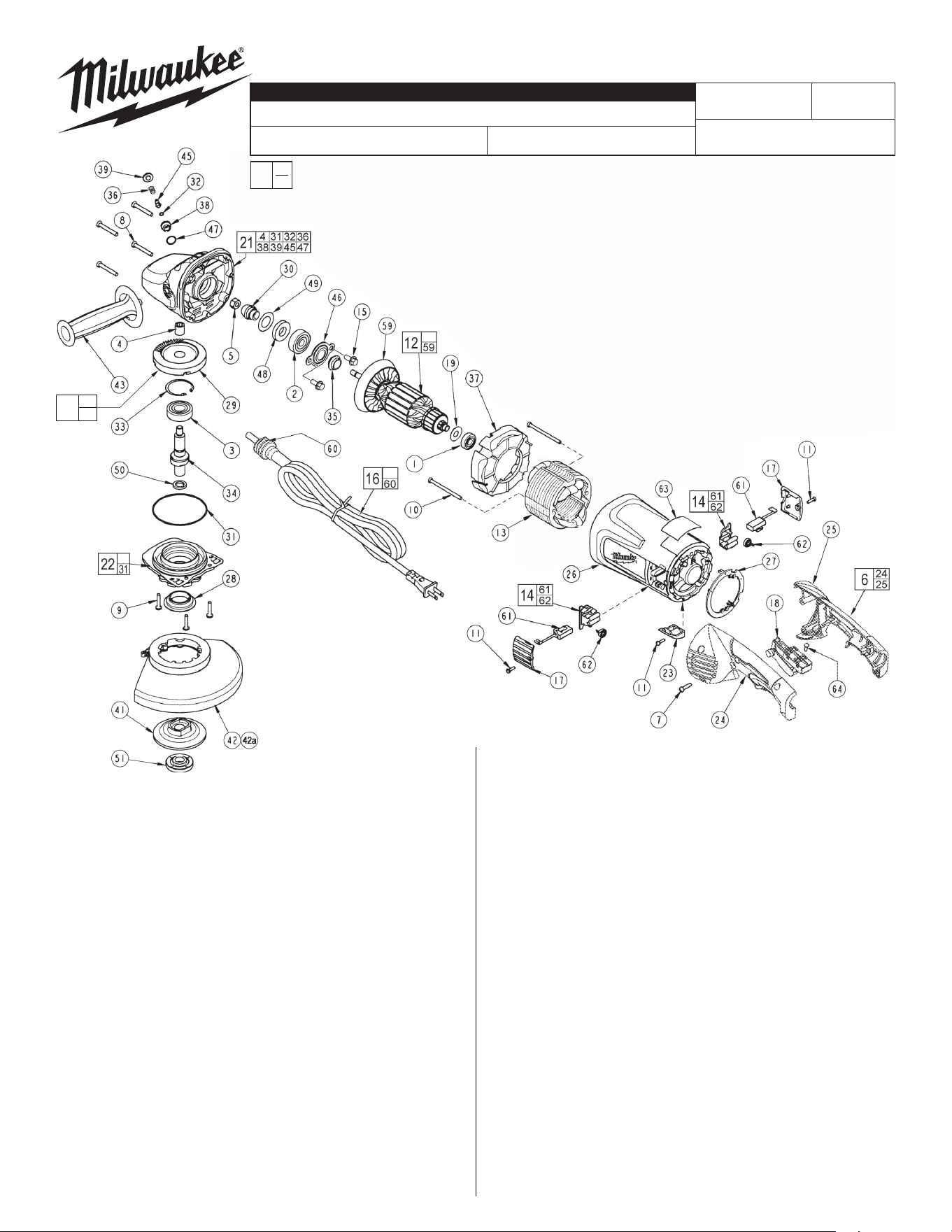
FIG. PART NO. DESCRIPTION OF PART NO REQ.
1 02-04-1675 Ball Bearing (1)
2 02-04-1680 Ball Bearing (1)
3 02-04-1745 Ball Bearing (1)
4 02-50-2429 Needle Bearing (1)
5 06-55-2455 Hex Nut (1)
6 14-34-0561 Handle Kit (1)
7 06-82-0055 8-16 Torx Plastite Screw T-20 (5)
8 06-82-0060 10-14 Torx Plastite Screw T-25 (4)
9 06-82-0065 10-32 x 1 Pan Hd. Taptite T-25 Screw (3)
10 06-82-0070 8-16 Torx Plastite Screw T-15 (2)
11 06-82-7240 6-19 x 1/2 Slt. Pan Hd. Plast. T-15 (3)
12 16-70-7132 Armature Assembly (1)
13 18-70-7130 Field (1)
14 22-20-0120 BrushHolderAssemblyw/Pop-O (2)
15 06-75-0510 1/4-20 x .62 Hex Flange Screw (2)
16 22-64-3601 Cord Set (Incl. Cord Protector & Terminals) (1)
17 23-44-0255 Brush Cover (2)
18 23-66-2721 Switch (1)
19 23-86-0160 Dust Seal (1)
21 28-14-1131 Gearcase Assembly (1)
22 28-53-0151 Spindle Hub Assembly (1)
23 31-15-0166 Cover (1)
24 --------------- Left Hand Handle Halve (1)
25 --------------- Right Hand Handle Halve (1)
26 31-50-1785 Motor Housing (1)
27 31-53-0161 Plug (1)
28 31-55-0150 Bearing Shield (1)
29 --------------- Gear (1)
30 --------------- Pinion Gear (1)
31 34-40-0505 O-Ring (1)
SANDERS / GRINDERS (7"/9" with LOCK-ON)
Apr. 2024
REVISED BULLETIN
SERVICE PARTS LIST
BULLETIN NO.
WIRING INSTRUCTION
DATE
SPECIFY CATALOG NO. AND SERIAL NO. WHEN ORDERING PARTS
CATALOG NO.
FIG. PART NO. DESCRIPTION OF PART NO REQ.
32 34-40-4300 O-Ring (1)
33 34-80-2960 Retaining Ring (1)
34 38-50-2500 Spindle Shaft (1)
35 31-55-0290 Dust Shield (1)
36 40-50-1550 Compression Spring (1)
37 42-14-0425 Bae (1)
38 42-30-0150 Lock Body (1)
39 42-42-0290 Button (1)
41 43-34-0825 5/8 Back Flange (1)
42 49-12-0010 7" Guard Assembly (Type 27) (1)
42a 49-12-0020 9" Guard Assembly (Type 27) (1)
43 43-62-1266 Side Handle (1)
45 44-60-1650 Lock Pin (1)
46 44-86-0040 Bearing Retainer (1)
EXAMPLE:
Component Parts (Small #)
Are Included When Ordering
The Assembly (Large #).
0
00
FIG. PART NO. DESCRIPTION OF PART NO REQ.
47 34-40-4555 O-Ring (1)
48 45-06-0710 Seal (1)
49 45-88-7880 Shim Washer (1)
50 45-88-8466 5/8-11 Spindle Washer (1)
51 49-05-0110 Flange Nut (1)
59 22-84-0540 Fan Assembly (1)
60 --------------- Cord Protector (1)
61 22-18-0126 CarbonBrushAssemblyw/Pop-O (2)
62 --------------- Brush Spring (2)
63 12-99-5008 Nameplate Blank (1)
64 05-78-0305 Switch Screw (4)
65 14-46-0360 Bevel Gear and Pinion Kit (1)
80 49-96-7205 Spanner Wrench (Not Shown) (1)
81 10-98-6085 Warning Label,
French & Spanish (Not Shown)
(1)
FIG. LUBRICATION:
21 1.25 oz. (35 grams) of Type "Y" grease, No. 49-08-5270 in
main gear cavity of gearcase.
29,30 "Y" grease must be applied to all gear teeth.
31,32 Lightly coat o-rings with "Y" grease prior to installation.
FIG. NOTES:
4,21 Pressneedlebearingush±.02togearcasebossface.
33 Bevel side of retaining ring away from bearing face.
FIG. NOTES:
5 Torque to 140 in.-lbs.
7,10 Torque to 20 in.-lbs.
8 Torque to 30 in.-lbs.
9 Torque to 35 in.-lbs.
15 Torque to 65-75 in.-lbs.
64 Torque to 4 in.-lbs.
54-38-1561
MILWAUKEE TOOL
l
www.milwaukeetool.com
13135 W. LISBON RD., BROOKFIELD, WI 53005
Drwg. 3
SERIAL NO.
x5
x4
29
30
65