
1
2
3
4
5
6
78
1
27
28
26
23
29
30
31
33
34
35
32
24
25
59
20
22
21
19
21
22
18
6
17
16
910
11
12
13
15
36
37
38
39
40
42
43
44
45
46
47
48
50
49
5251
58
57
56
55
54
60
61
62
63
60 61
62
64
40 41 42 43 44 45 46
47 48 49 50 51 52
41
65
19 21
22
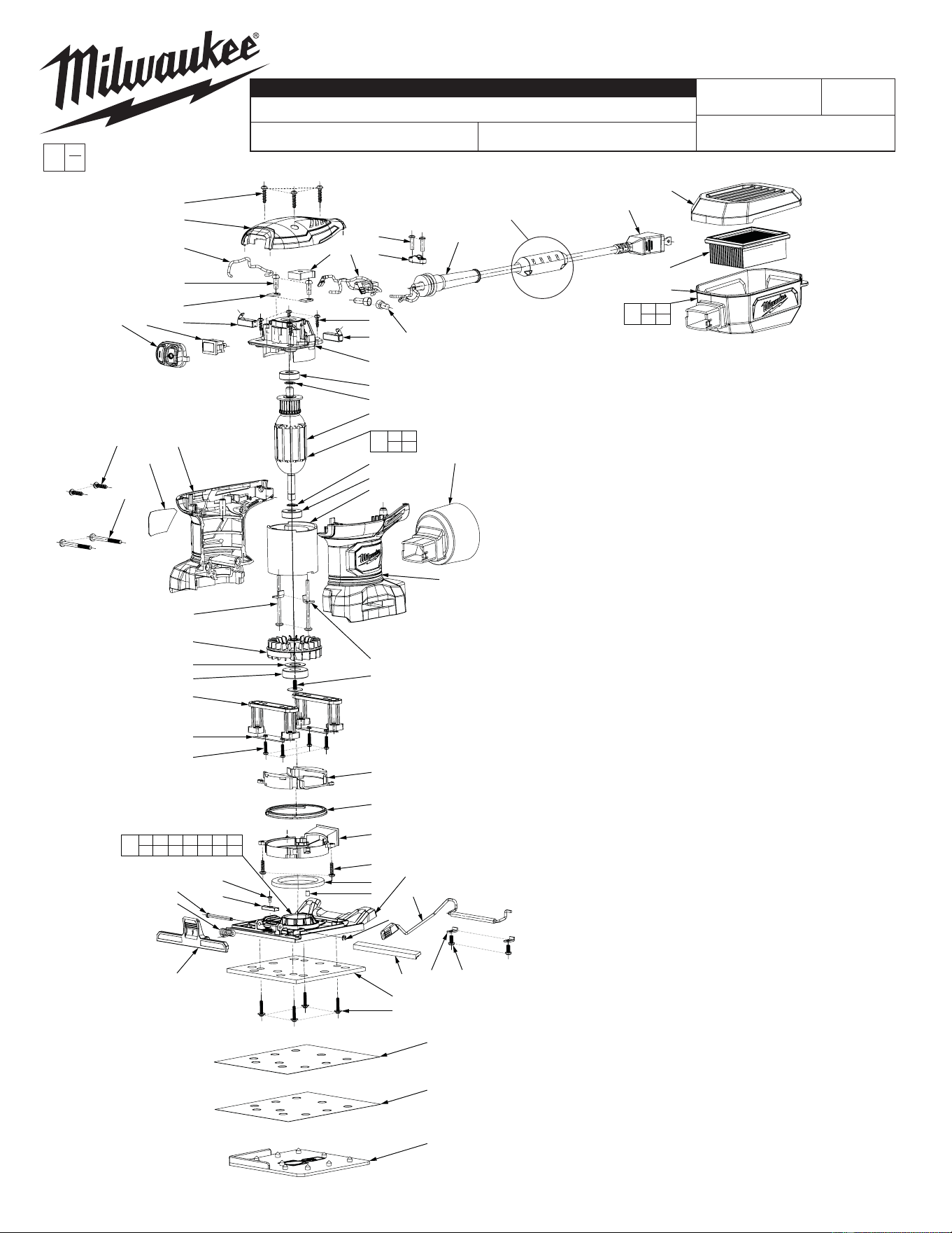
FIG. PART NO. DESCRIPTION OF PART NO. REQ.
1 06-81-0145 8-18 x 5/8" Pan Hd. T-15 Screw 5
2 31-12-0025 Top Cap 1
3 23-94-2661 Black Wire 1
4 05-74-0995 8-16 x 1/2" Pan Hd. T-20 Screw 2
5 22-38-0180 Brush Clamp 2
6 22-18-1170 Carbon Brush Assembly w/Shunt Wire 2
7 23-66-0245 Switch 1
8 42-38-0165 Rubber Cap 1
9 23-38-2855 Rectifi er 1
10 22-80-0106 Electronics Assembly 1
11 06-81-0150 6-19 x 5/8" Pan Hd. T-15 Screw 2
12 31-17-0530 Cord Clamp 1
13 44-76-0315 Strain Relief 1
15 22-64-1210 Cord 1
16 22-56-5317 Wire Connector (see wiring) 2
17 06-81-0135 6-19 x 7/16" Pan Hd. T-15 Screw 4
18 31-12-0390 Bearing Housing 1
19 --------------- Armature 1
20 18-10-0142 Field 1
21 --------------- Retaining Ring 2
22 --------------- Bearing 2
23 06-81-0130 8-10 x 2-1/8" Pan Hd. T-20 Screw 2
24 42-70-1005 Field Retaining Clip 2
25 31-50-0595 Housing Support 1
26 31-50-0605 Housing Cover 1
27 06-82-0170 M4 x 43mm Pan Hd. T-20 ST Screw 2
28 12-20-6033 Service Nameplate 1
29 22-84-0045 Fan 1
30 45-88-1970 Washer 1
31 02-04-5155 Bearing 1
32 06-81-0165 8-32 x 3/8" Pan Washer Hd. T-20 Screw 1
33 45-60-0035 Cushion Post 2
34 44-52-0960 Retaining Clip 2
35 05-81-0195 M3 x 12mm Pan Hd. Screw 4
36 31-05-0125 Fan Cap 1
37 31-05-0135 Fan Ring 1
38 31-05-0145 Fan Guide 1
39 06-81-0115 6-19 x 1/2" Pan Hd. T-15 Screw 2
40 31-76-0155 Dust Shield 1
41 --------------- Base Plate 1
42 --------------- Plug 1
43 --------------- M2.6 x 6mm Flat Hd. Philips Screw 1
44 --------------- Counterweight 1
45 --------------- Pin 1
46 --------------- Torsion Spring 1
47 --------------- Front Clamp Bar 1
48 --------------- E-Ring 1
49 --------------- Cushion 1
50 --------------- Rear Spring Clamp Assembly 1
51 --------------- Retaining Plate 2
52 --------------- 6-19 x 5/16" Torx T-15 Screw 2
54 44-66-0475 Aluminum Plate w/ Cushion Pad 1
55 05-74-0305 M3 x 15mm Pan Hd. T-20 Screw 4
56 --------------- 100 Grit Sand Paper 1
57 --------------- 150 Grit Sand Paper 1
58 44-66-0465 Paper Punch 1
59 31-03-0075 VAC Adapter 1
60 --------------- Dust Box Cover w/ Rubber Gasket 1
61 --------------- Dust Box Filter 1
62 --------------- Dust Box Body 1
63 31-15-0640 Dust Box Assembly 1
64 31-06-0135 Base Plate Assembly 1
65 16-07-0160 Armature Assembly 1
BULLETIN NO.
54-38-0510
SERVICE PARTS LIST
CATALOG NO. 6033-21
REVISED BULLETIN
SPECIFY CATALOG NO. AND SERIAL NO. WHEN ORDERING PARTS
1/4 SHEET PALM SANDER
STARTING
SERIAL NO.
DATE
Aug. 2015
WIRING INSTRUCTION
G65A
EXAMPLE:
Component Parts (Small #)
Are Included When Ordering
The Assembly
(Large #).
0
00
See Reverse Side
MILWAUKEE TOOL
www.milwaukeetool.com
13135 W. Lisbon Road, Brookfi eld, Wisc. 53005
Drwg. 1
NOTE: This assembly contains
the sensormatic label. It is not a
serviceable part.
NOTE: Fig. 28. A
clean, dry surface
is essential for
proper perfor-
mance for any
adhesive system.
The area intended
for application of
any adhesive label
or nameplate must
be prepared by
cleaning with iso-
propyl alcohol. The
solvent is to be ap-
plied with a clean,
lint free applicator
and the surface al-
lowed to dry before
applying the label
or nameplate.
NOTE: Figs. 54, 56, and
57 must be oriented as
shown, with two holes at
front and three at back.
NOTE: Fig. 6. As
an aide to installa-
tion, brushes may
have to be put in at
a slight angle.
NOTE: Fig. 55. Place all four
screws in before tightening.
Do not overtighten.
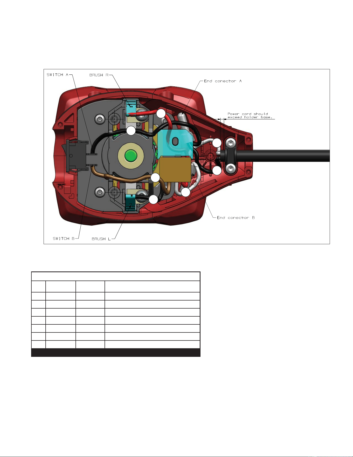
WIRING SPECIFICATIONS
Wire
No.
Wire
Color
Origin or
Gauge
Terminals, Connectors and 1 or 2 End Wire Preparation
1 White 22-64-1210 Power Cord
2 Black 22-64-1210 Power Cord
3 Black 22-80-0106 Electronics Assembly
4 Brown 22-80-0106 Electronics Assembly
5 White 22-80-0106 Electronics Assembly
6 Red 22-80-0106 Electronics Assembly
7 Black 23-66-0245 Switch
BULK LEAD WIRE - BULLETIN 58-01-0003
NOTE:
As an aid to reassembly, take note of the wire routings and position of the wires in the wire guides and wire guides traps prior to dismantling the tool.
Watch for pinched wires when placing the handle cover back over the housing assembly.
WIRING INSTRUCTIONS
2
1
6
7
3
4
5