Version V1.1
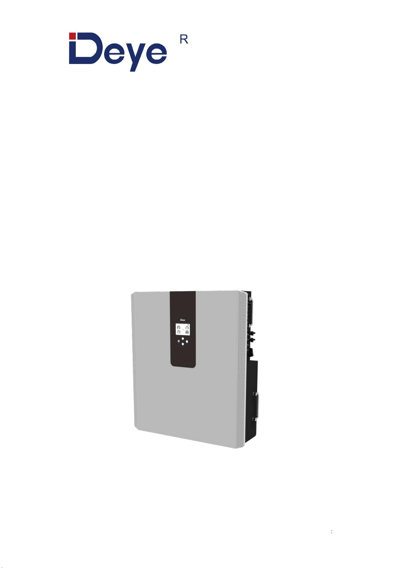
All-in-One ESS (LV)
RW-F5.3-1H3
RW-F5.3-2H3
USER MANUAL

Contents
1.Safety Introductions ..........................................................................................................................................1
2.Product Introduction ..........................................................................................................................................3
3.Specifications ....................................................................................................................................................3
4.Unpacking Guide .............................................................................................................................................. 5
5.Packing List .......................................................................................................................................................5
5.1 Parts List .................................................................................................................................................5
5.2 Product handling requirements ..............................................................................................................6
5.3 Installations Tools ...................................................................................................................................6
6.Security Introduction .........................................................................................................................................7
6.1 Preparation Before Connection ............................................................................................................. 7
6.2 In Use ..................................................................................................................................................... 8
7.Quick Guide ...................................................................................................................................................... 9
7.1 Product Dimensions ............................................................................................................................... 9
7.2 Operation Interface .............................................................................................................................. 10
7.3 Display ICONS ..................................................................................................................................... 11
8.Mechanical Installation ................................................................................................................................... 12
8.1 Considering the following points before selecting where to install: .................................................... 12
8.2 Mounting the ESS ................................................................................................................................ 12
8.3 Function port definition .........................................................................................................................14
8.3.1 Interface definition ..................................................................................................................... 15
8.4 Grid connection and backup load connection ..................................................................................... 19
8.5 PV Connection ..................................................................................................................................... 21
8.5.1 PV Module Selection: ................................................................................................................ 21
8.5.2 PV Module Wire Connection: .................................................................................................... 21
8.6 CT Connection ..................................................................................................................................... 24
8.7 Meter Connection .................................................................................................................................25
8.8 Earth Connection (mandatory) .............................................................................................................26
9.Product Wiring Instructions ............................................................................................................................ 27
9.1 Cables for Battery Expansion .............................................................................................................. 27
9.2 Parallel Capacity Expansion ................................................................................................................ 27
9.3 Typical Application Diagram of Diesel Generator ............................................................................... 28
9.4 Single Phase Parallel Connection Diagram ........................................................................................ 29
9.5 Three Phase Parallel Inverter .............................................................................................................. 30
9.6 Wiring System for Inverter ................................................................................................................... 31
10.Activation product ......................................................................................................................................... 32
11.LCD Display Icons ........................................................................................................................................ 33
11.1 Main Screen ....................................................................................................................................... 33
11.1.1 LCD Operation Flow Chart ...................................................................................................... 34
11.2 Solar Power Curve ............................................................................................................................. 35
11.2 Curve Page-Solar & Load & Grid ...................................................................................................... 36
11.3 System Setup Menu ...........................................................................................................................37
11.4 Basic Setup Menu .............................................................................................................................. 37
11.5 Battery Setup Menu ........................................................................................................................... 38
11.6 System Work Mode Setup Menu .......................................................................................................40
11.7 Grid Setup Menu ................................................................................................................................ 42
11.8 The Method of CEI-021 Standard Self-Check ...................................................................................44
11.9 Generator Port Use Setup Menu ....................................................................................................... 46
11.10 Advanced Function Setup Menu ..................................................................................................... 47
11.11 Device Info Setup Menu ...................................................................................................................48
12.Fault Content ................................................................................................................................................ 49
12.1 Fault Information and Processing ......................................................................................................49
12.2 Low Voltage Fault Analysis Method .................................................................................................. 49
13.FAQ ...............................................................................................................................................................54
14.After-Sales Service .......................................................................................................................................55
15.EU Declaration of Conformity .......................................................................................................................55
1
About This Manual
The manual mainly describes the product information, guidelines for installation, operation and
maintenance. The manual cannot include complete information about the photovoltaic (PV)
system.
How to Use This Manual
Read the manual and other related documents before performing any operation on the inverter.
Documents must be stored carefully and be available at all times.
Contents may be periodically updated or revised due to product development. The information
in this manual is subject to change without notice. The latest manual can be acquired via
service@deye.com.cn
1.Safety Introductions
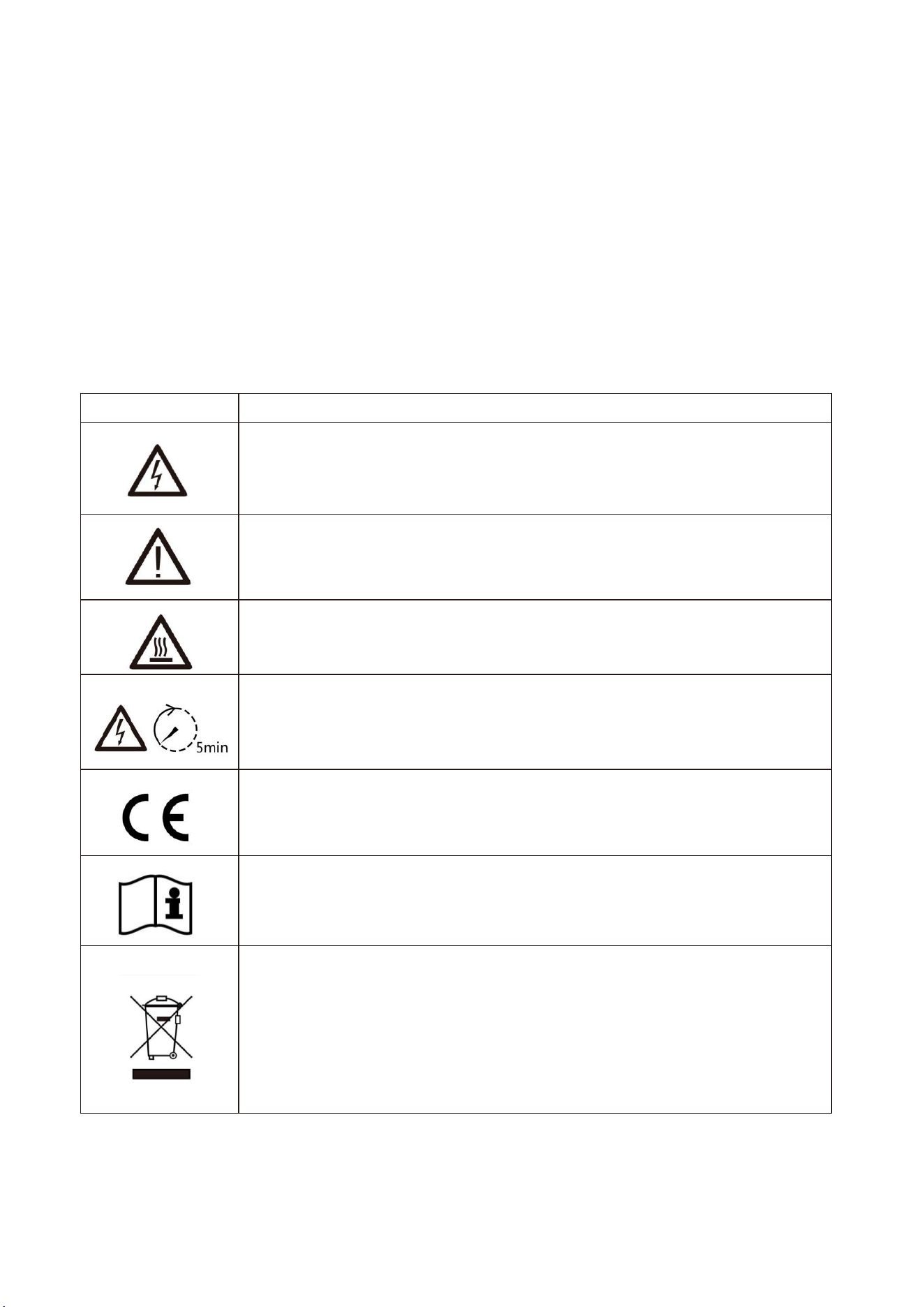
Labels description
Label
Description
Caution, risk of electric shock symbol indicates important safety
instructions, which if not correctly followed, could result in electric shock.
The DC input terminals of the inverter must not be grounded.
Surface high temperature, Please do not touch the inverter case.
The AC and DC circuits must be disconnected separately, and the
maintenance personnel must wait for 5 minutes before they are completely
powered off before they can start working.
CE mark of conformity
Please read the instructions carefully before use.
Symbol for the marking of electrical and electronics devices according to
Directive 2002/96/EC. Indicates that the device, accessories and the
packaging must not be disposed as unsorted municipal waste and must
be collected separately at the end of the usage. Please follow Local
Ordinances or Regulations for disposal or contact an authorized
representative of the manufacturer for information concerning the
decommissioning of equipment.

2
This chapter contains important safety and operating instructions. Read and keep this manual for
future reference.
Before using the inverter, please read the instructions and warning signs of the battery and
corresponding sections in the instruction manual.Do not disassemble the inverter. If you need
maintenance or repair, take it to a professional service center.
Improper reassembly may result in electric shock or fire.
To reduce risk of electric shock, disconnect all wires before attempting any maintenance or
cleaning. Turning off the unit will not reduce this risk.
Caution: Only qualified personnel can install this device with battery.
Never charge a frozen battery.
For optimum operation of this inverter, please follow required specification to select appropriate
cable size. It is very important to correctly operate this inverter.
Be very cautious when working with metal tools on or around batteries. Dropping a tool may
cause a spark or short circuit in batteries or other electrical parts, even cause an
explosion.Please strictly follow installation procedure when you want to disconnect AC or DC
terminals. Please refer to "installation" section of this manual for the details.
Grounding instructions - this inverter should be connected to a permanent grounded wiring
system. Be sure to comply with local requirements and regulation to install this inverter.Never
cause AC output and DC input short circuited. Do not connect to the mains when DC input short
circuits.
3
2.Product Introduction
This is an all-in-one hybrid inverter Energy storage system, combining functions of inverter, solar
charger and LFP battery to offer uninterruptible power support with portable size. its comprehensive
LCD display offers user configurable and easy accessible button operation such as battery charging,
AC/solar charging, and acceptable input voltage based on different applications.
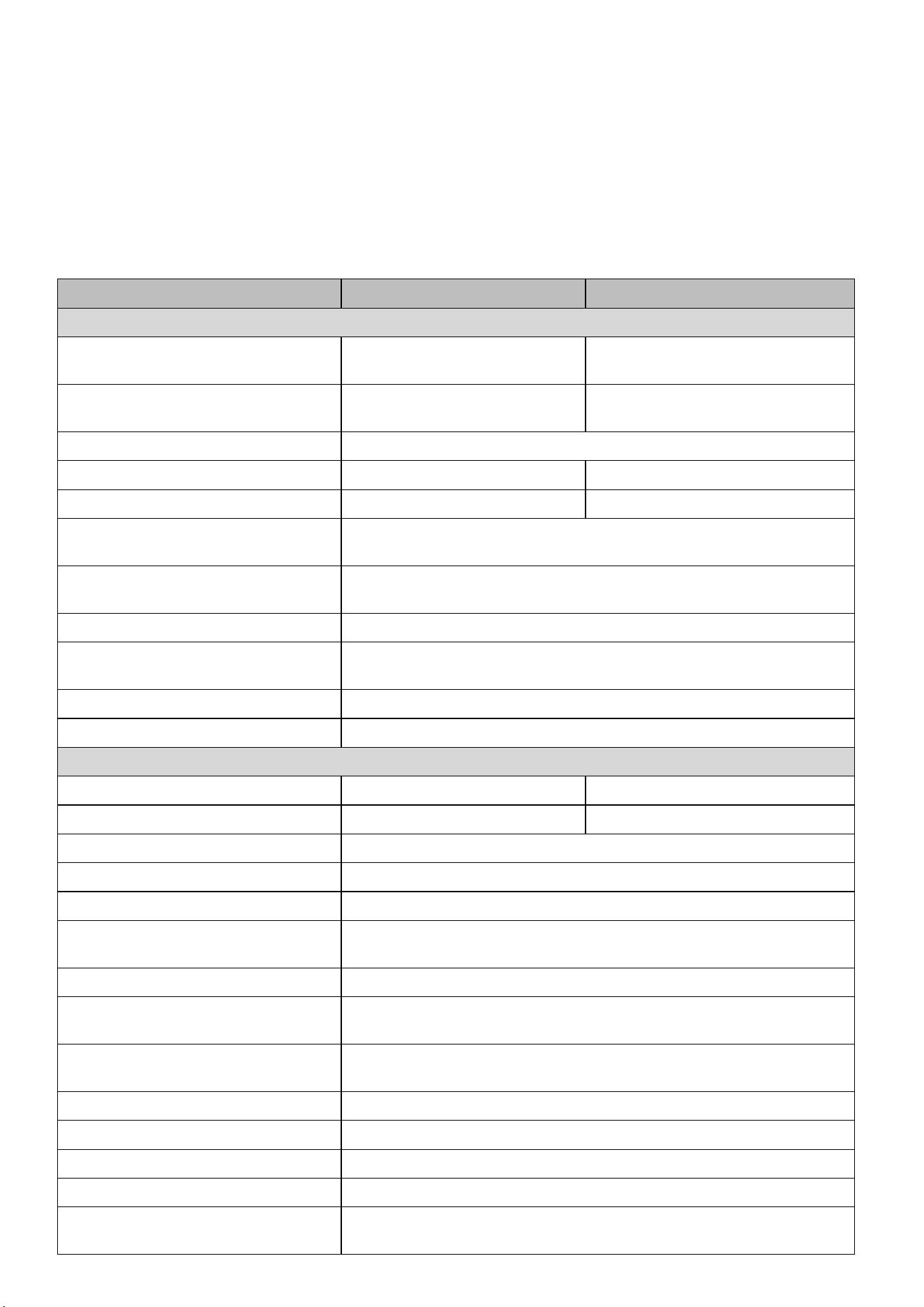
3.Specifications
Model
RW-F5.3-2H3
RW-F5.3-1H3
AC Technical Specification
Rated AC Input/Output Active
Power (W)
3600 / 3600
5000 / 5000
Max AC Input/Output Apparent
Power (VA)
3960
5500
Peak Power (off grid)
2 time of rated power, 10s
Rated AC Input/Output Current (A)
16.4/15.7
22.8/21.8
Max. AC Input/Output Current (A)
18/17.3
25/24
Max Continuous AC Passthrough
(grid to load) (A)
35
Rated Input/Output Voltage/Range
(V)
220V/230,0.85Un-1.1Un
Grid Connection Form
L+N+PE
Rated Input/Output Grid
Frequency/Range
50Hz/45Hz-55Hz, 60Hz/55Hz-65Hz
Power Factor Adjustment Range
0.8 leading to 0.8 lagging
Total Harmonic Distortion (THD)
<3% (of nominal power)
DC Technical Specification
Max. PV Access Power (W)
7200
10000
Max. PV Input Power (W)
5760
8000
Max. PV Input Voltage (Vdc)
500
Start Up PV Voltage (Vdc)
125
MPPT Voltage Range (Vdc)
150 to 425
Full Load MPPT Voltage Range
(Vdc)
300 to 425
Rated PV Input Voltage (Vdc)
370
Max. Operating PV Input Current
(A)
18+18
Max. PV Input Short-circuit
Current (A)
27+27
Number of MPP Trackers
2
No. of Strings Per MPP Tracker
1 + 1
Battery Chemistry
LiFePO4
Battery Nominal Voltage (V)
51.2
Battery Energy Configuration
(kWh)
5.32

4
Max. Charging/Discharging
Current (A)
75
100
Battery Operating Voltage (V)
44.8 to 57.6
Battery Cycle Life
≥
6000(@25
℃±
2
℃
,0.5C/0.5C,70%EOL)
General Technical Specification
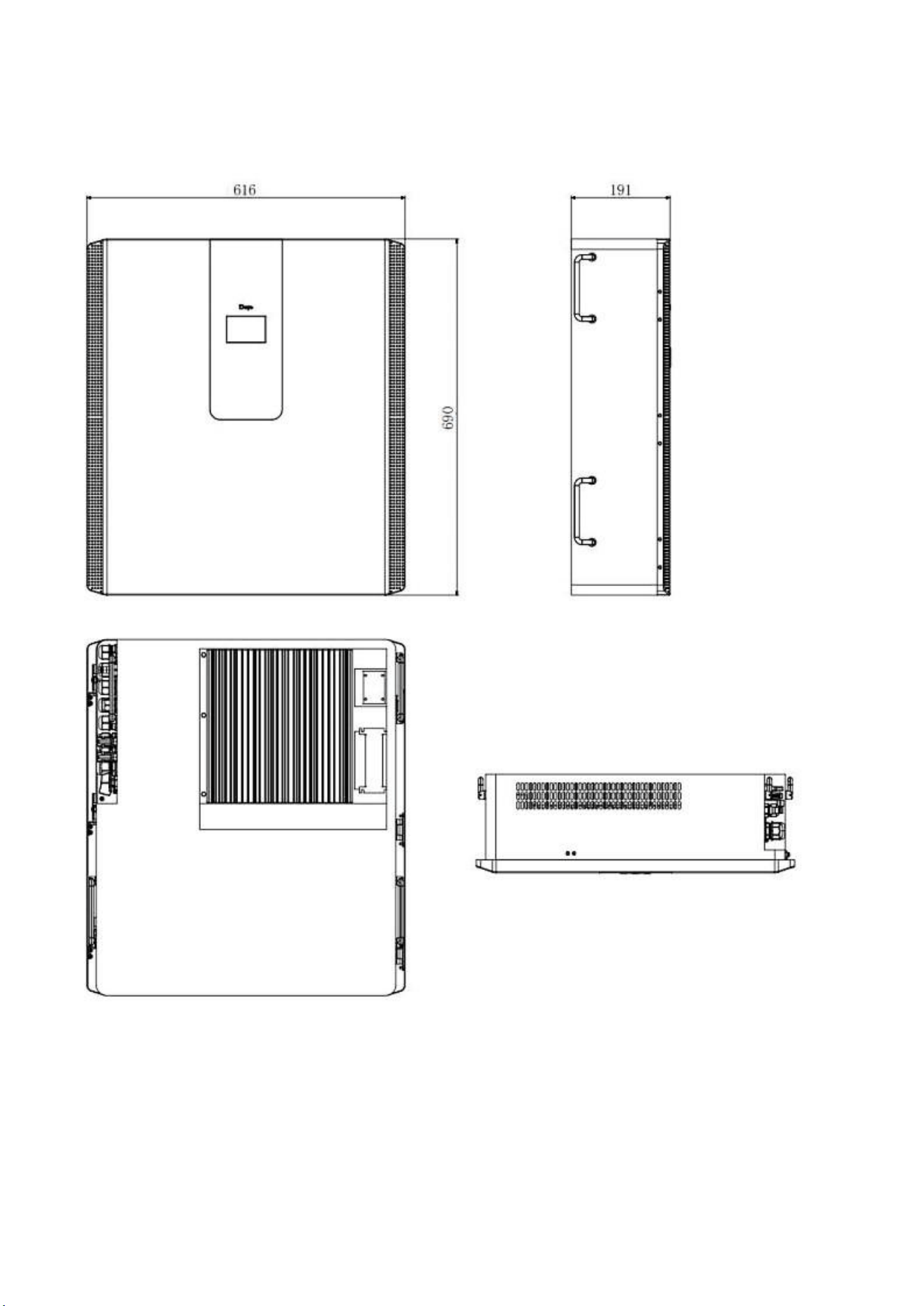
Dimension (W x D x H,mm)
616
×
191
×
690 (Excluding connectors and brackets)
Weight Appr. (kg)
71
Ingress Protection(IP) Rating
IP65
Operating Temperature Range
-10
℃
to 55
℃
(>45
℃
derating)
Permissible Ambient Humidity
0 to 100%
Permissible Altitude
2000m
Inverter Topology
Non-Isolated
Over Voltage Category
OVC II(DC),OVC III(AC)
Pollution degree (PD)
PD3
Type Of Cooling
Natural Cooling
Noise(dB)
<30
Display
Touch LCD
Monitor Mode
WIFI, Bluetooth
Installation Style
Wall-Mounted, Floor-Mounted
Max. Efficiency
97%
Max. charging/discharging
Efficiency
95.5%
MPPT Efficiency
>99%
Safety EMC / Standard
IEC/EN 61000-6-1/2/3/4, IEC/EN 62109-1, IEC/EN 62109-2,
IEC62619, UN38.3
Grid Regulation
IEC 61727,IEC 62116,CEI 0-21,EN 50549,NRS 097,RD 140,
UNE 217002,OVE-Richtlinie R25,G99,VDE-AR-N 4105
Warranty
5/10 years
(the Warranty Period Depends the Final Installation Site.More
Info Please Refer to Warranty Policy)
5
4.Unpacking Guide
Check the outer packing
Before unpacking the outer package, check the outer package for visible damage, such as holes,
cracks, or other signs of possible internal damage, and check the energy storage model. If there is
any abnormal packaging or energy storage model does not match, do not open, and contact your
dealer as soon as possible.
Check deliverables
After unpacking the outer packaging of the energy storage, check that the deliverables are complete
and there is no obvious external damage. If anything is missing or damaged, contact your dealer.
Note: For the quantity of deliverables shipped with the box, please refer to the Packing List in the box.
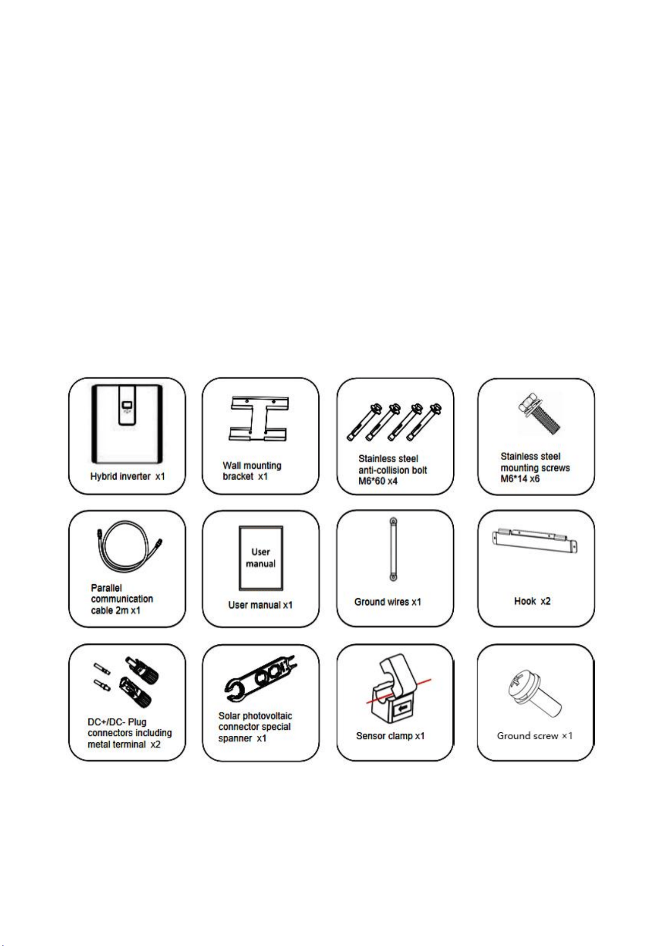
5.Packing List
5.1 Parts List
Check the equipment before installation. Please make sure nothing is damaged in the package.You
should have received the items in the following package:
6
5.2 Product handling requirements
Lift the inverter out of the packing box and transport it to designated installation location.
CAUTION:
Improper handling may cause personal injury!
Arrange an appropriate number of personnel to carry the inverter according to its weight, and installation personnel should wear
protective equipment such as anti-impact shoes and gloves.
Placing the inverter directly on a hard ground may cause damage to its metal enclosure. Protective materials such as sponge pad or
foam cushion should be placed underneath the inverter.
Move the inverter by one or two people or by using a proper transport tool.
Move the inverter by holding the handles on it. Do not move the inverter by holding the terminals.
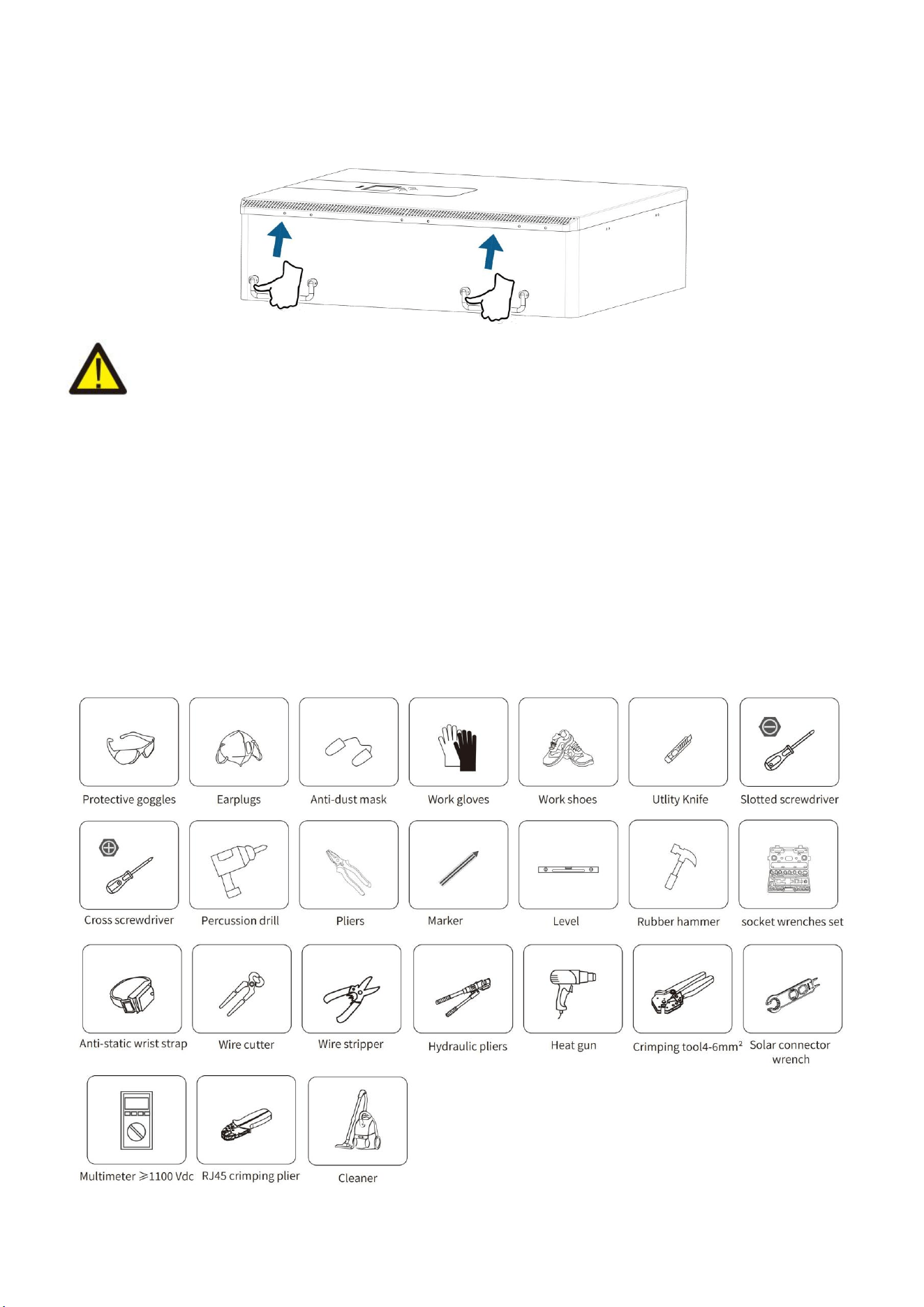
5.3 Installations Tools
Installation tools can refer to the following recommended ones. Also, use other auxiliary tools on site.

7
6.Security Introduction
Warning
1. It is very important and necessary to read the user manual (attached) carefully before installing or
using the battery. Failure to do so or to follow any instructions or warnings in this document may
result in electric shock, serious injury, or possible damage to the battery, rendering it inoperable.
2. If the battery is stored for a long time, it is recommended to charge the product once a month or
So, and the Soc should not be less than 50% .
3. Charge the battery within 48 hours after it is fully discharged.
4. Do not expose the cable.
5. Disconnect all power supplies during maintenance.
6. If any exception occurs, please contact the supplier within 24 hours.
7. Do not use cleaning solvents to clean the battery.
8. Do not expose this product to flammable or irritating chemicals or vapors.
9. It is prohibited to paint any part of this product, including any internal or external components.
10. Direct or indirect damages caused by the above reasons do not include warranty claims.
11. Do not insert any foreign matter into any part of the product.
Warning
6.1 Preparation Before Connection
1. After unpacking, please check the product and packing list. If the product is damaged or missing,
please contact the local retailer.
2. Before installation , disconnect the power supply from the power grid and ensure that the battery
is turned off.
3. Cables must be connected correctly and do not short-circuit external devices.
4. Keep away from fire.
5. Do not use non-official parts or accessories.
6. Do not stack other heavy objects on the product.
8
6.2 In Use
1. If you need to move or repair the product, you must disconnect the power supply and completely
turn off the product.
2. Do not connect batteries of different models.
3. Disassembly is prohibited.
4. In case of fire, only liquid fire extinguishers can be used. Dry fire extinguishers are prohibited.
5. Please AVOID direct sunlight, rain exposure, snow laying up during installation and operation.
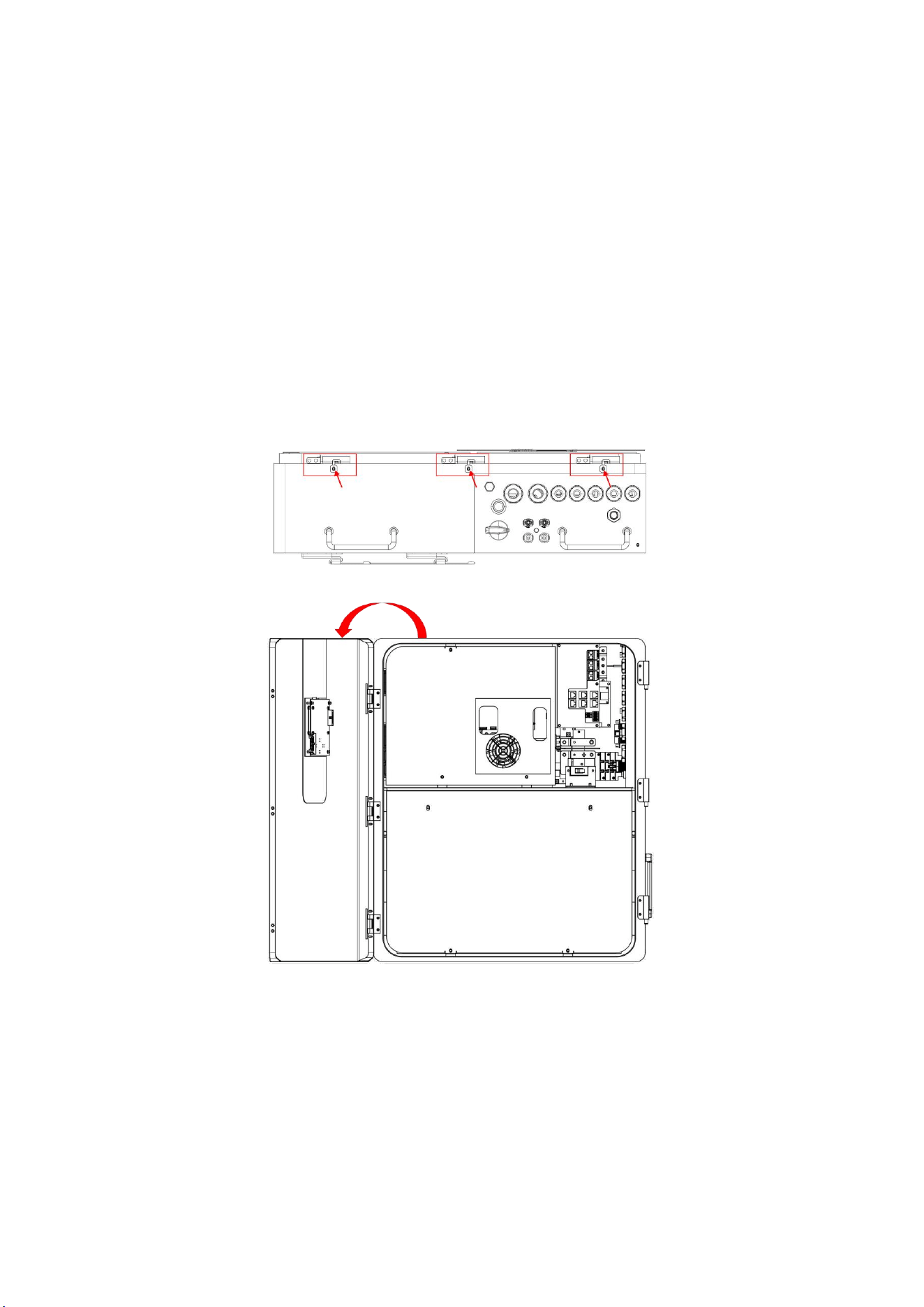
Before connecting all wires, please take off the metal cover by removing screws as shown below:
Remove the three screws pointed by the arrow.
Open the three latches to open the lid of the product.
9
7.Quick Guide
7.1 Product Dimensions
Unit:mm
10
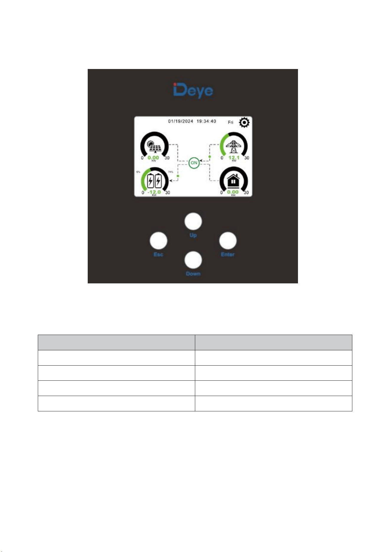
7.2 Operation Interface
Front panel display
Function Button
Description
ESC
exit mode
Up
Go back to the previous choice
Down
skip to the next selection
Enter
confirm selection
11
7.3 Display ICONS
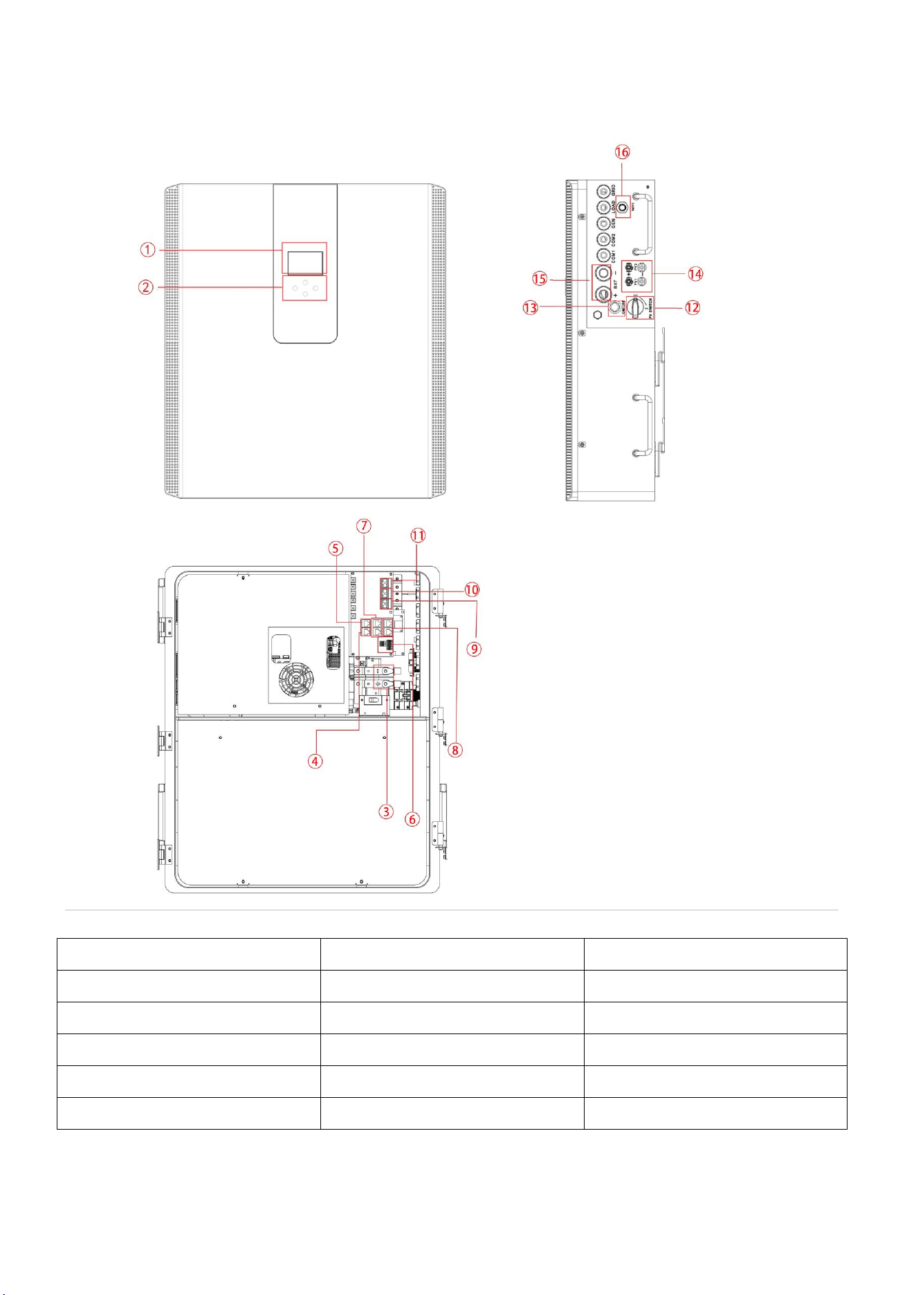
Product Overview
1. LCD display
7. Inverter Parallel port
12. DC Switch
2. Function Buttons
8. Battery Parallel port
13.Power on/off button
3. Battery input connectors
9. Generator input
14.PV input
4. RS485/CAN Port
10. Load
15.Battery
5. Meter Port
11. Grid
16.WiFi Interface
6. Function Port
12
8.Mechanical Installation
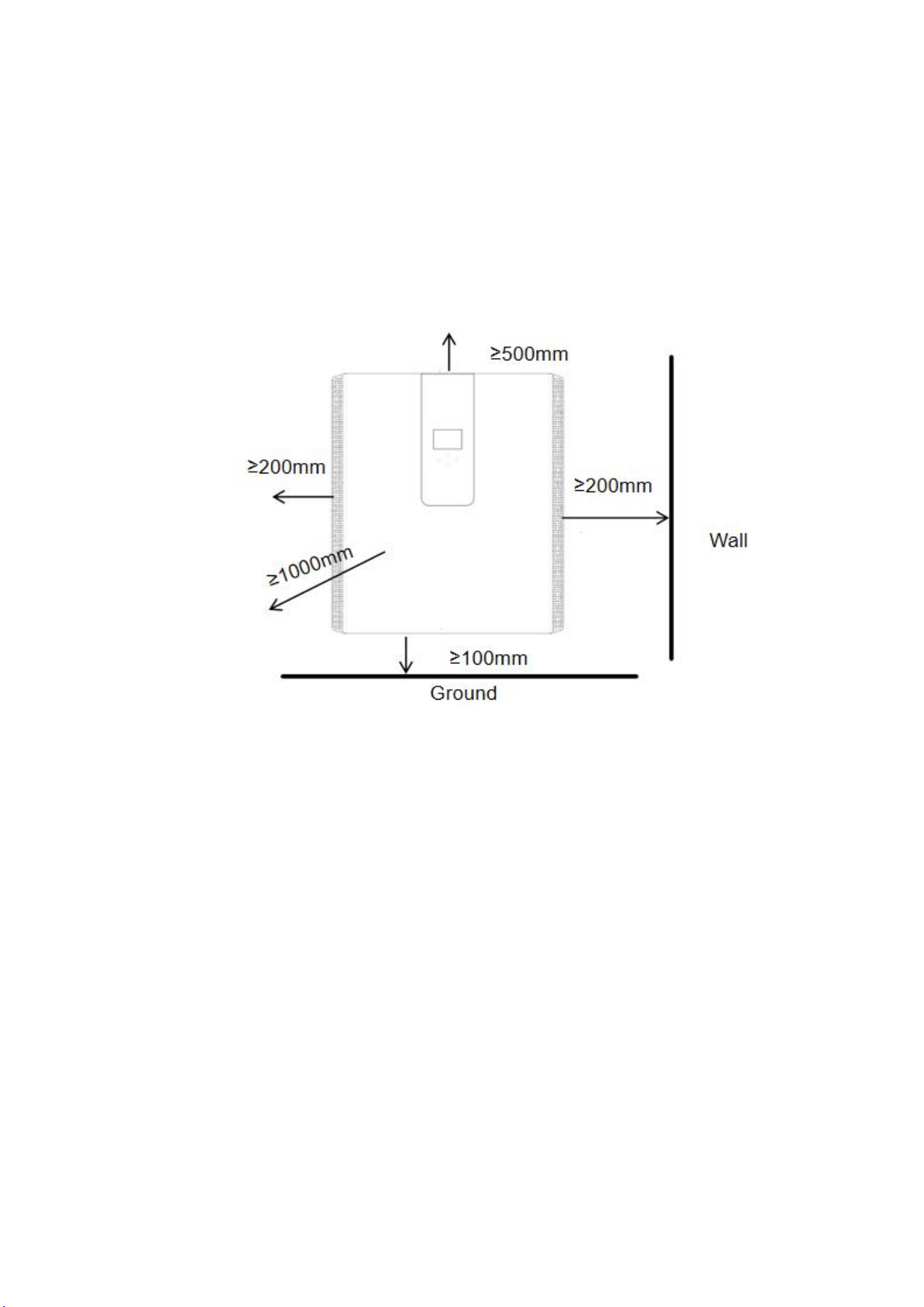
8.1 Considering the following points before selecting where to install:
Please select a vertical wall with load-bearing capacity for installation, suitable for installation on
concrete or other non-flammable surfaces, installation is shown below.
Install this inverter at eye level in order to allow the LCD display to be read at all times.
The ambient temperature is recommended to be between -10~40
℃
to ensure optimal operation.
Be sure to keep other objects and surfaces as shown in the diagram to guarantee sufficient heat
dissipation and have enough space for removing wires.
For proper air circulation to dissipate heat, the clearance is about: not less than 200mm on the
side, not less than 500mm above, not less than 100mm from the ground, and 100 cm further ahead.
8.2 Mounting the ESS
Remember that this ESS is heavy! Please be careful when lifting out from the package. Choose the
recommend drill head(as shown in below pic) to drill 4 holes on the wall,82-90mm deep.
Use a proper hammer to fit the expansion bolt into the holes.
Carry the ESS and holding it, make sure the hanger aim at the expansion bolt, fix the ESS on the
wall.
Fasten the screw head of the expansion bolt to finish the mounting.
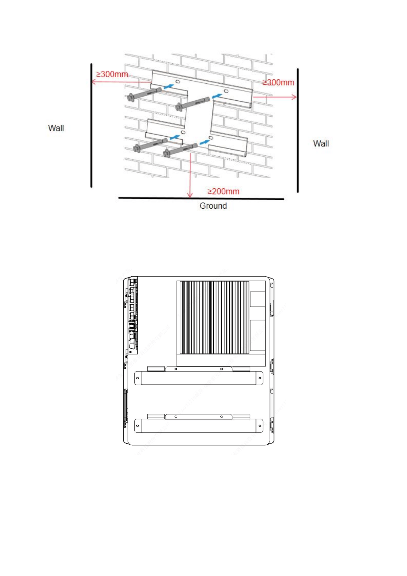
13
Wall mounting bracket installation
14
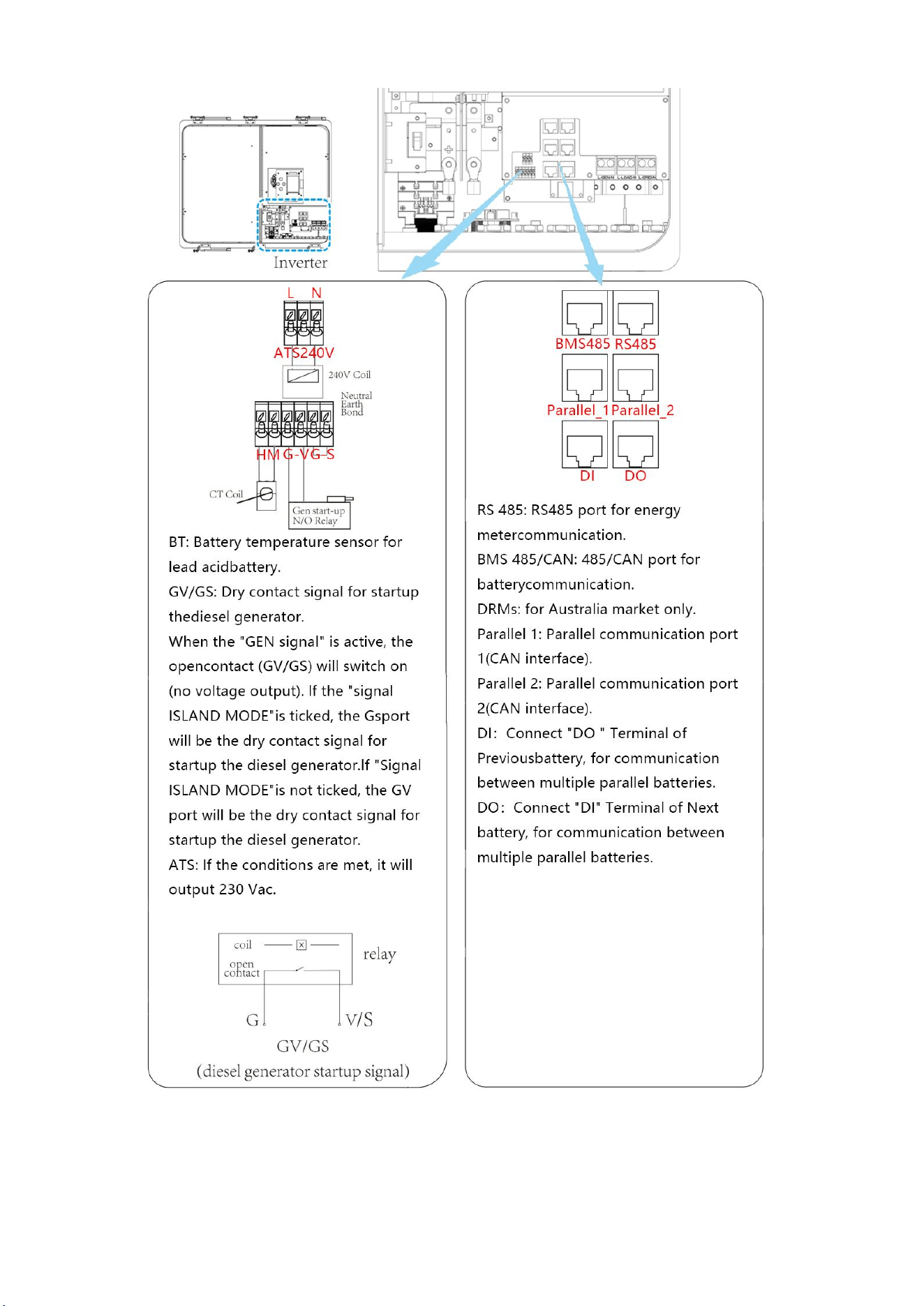
8.3 Function port definition
15
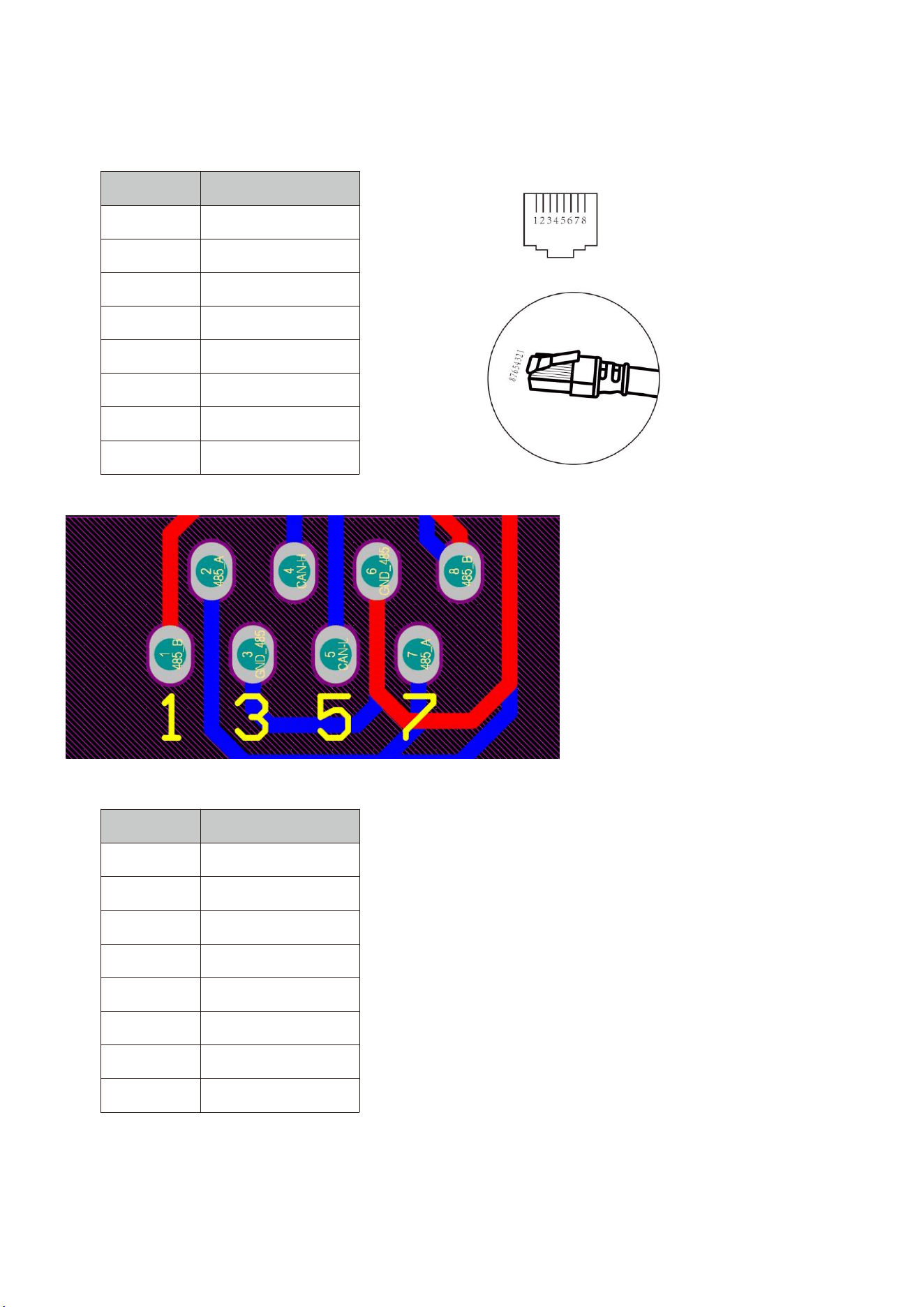
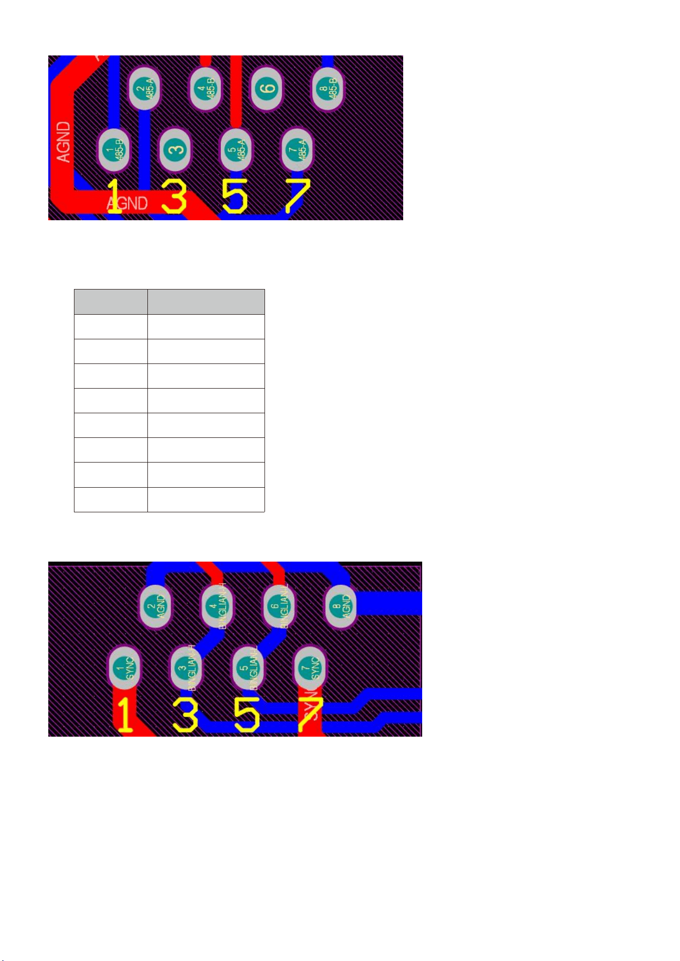
8.3.1 Interface definition
Definition of RJ45 Port Pin for BMS 485/CAN.
No.
BMS 485/CAN Pin
1
485-B
2
485-A
3
GND_485
4
CAN-H
5
CAN-L
6
GND_485
7
485-A
8
485-B
BMS485/CAN port
Definition of RJ45 Port Pin for RS 485.
No.
RS485 Pin
1
485-B
2
485-A
3
4
485-B
5
485-A
6
7
485-A
8
485-B
16
RS 485 Port
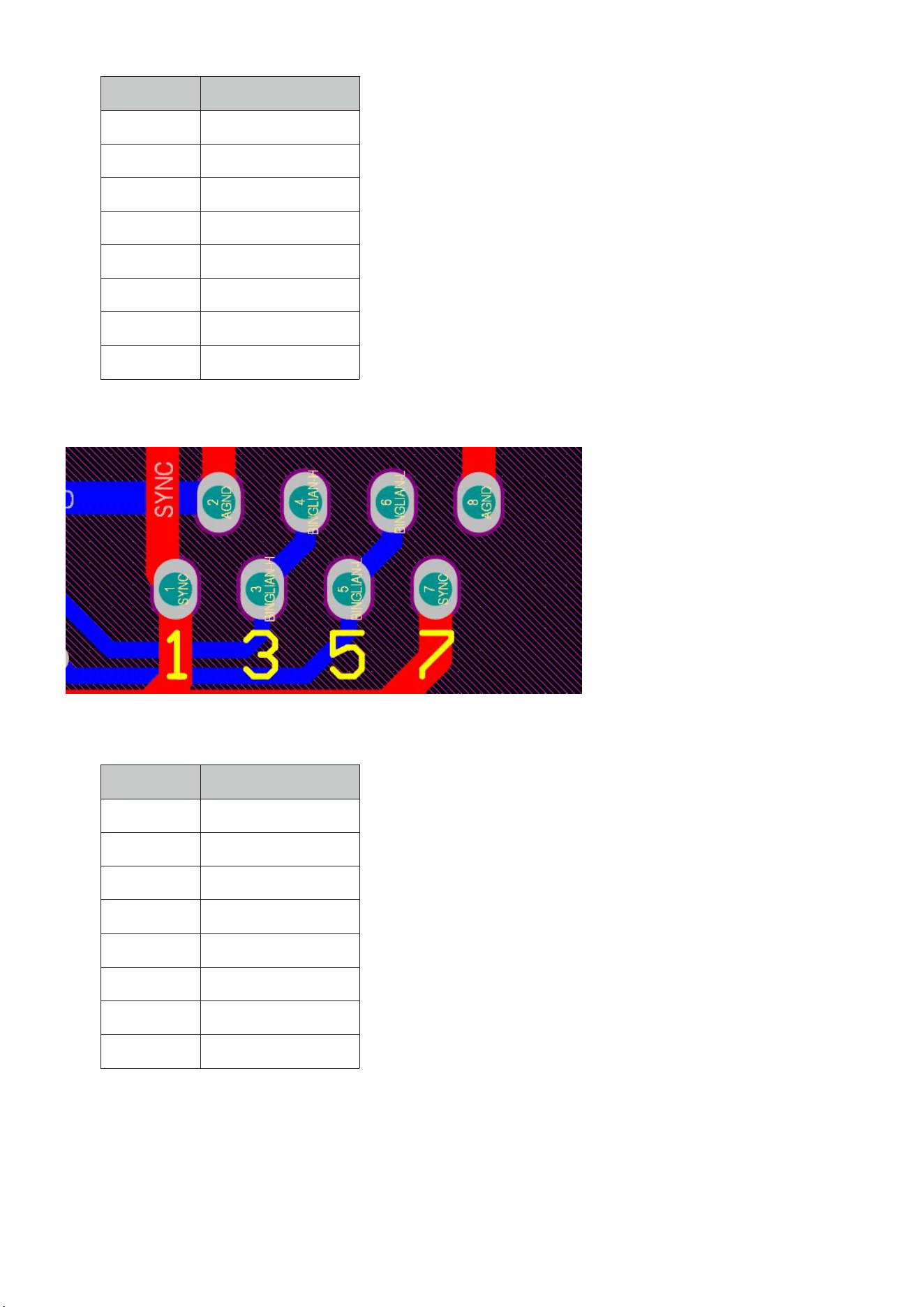
Definition of RJ45 Port Pin for parallel 1.
No.
parallel 1 Pin
1
SYNC
2
AGND
3
BINGLIAH-H
4
BINGLIAH-H
5
BINGLIAH-L
6
BINGLIAH-L
7
SYNC
8
AGND
RS 485 Port
17
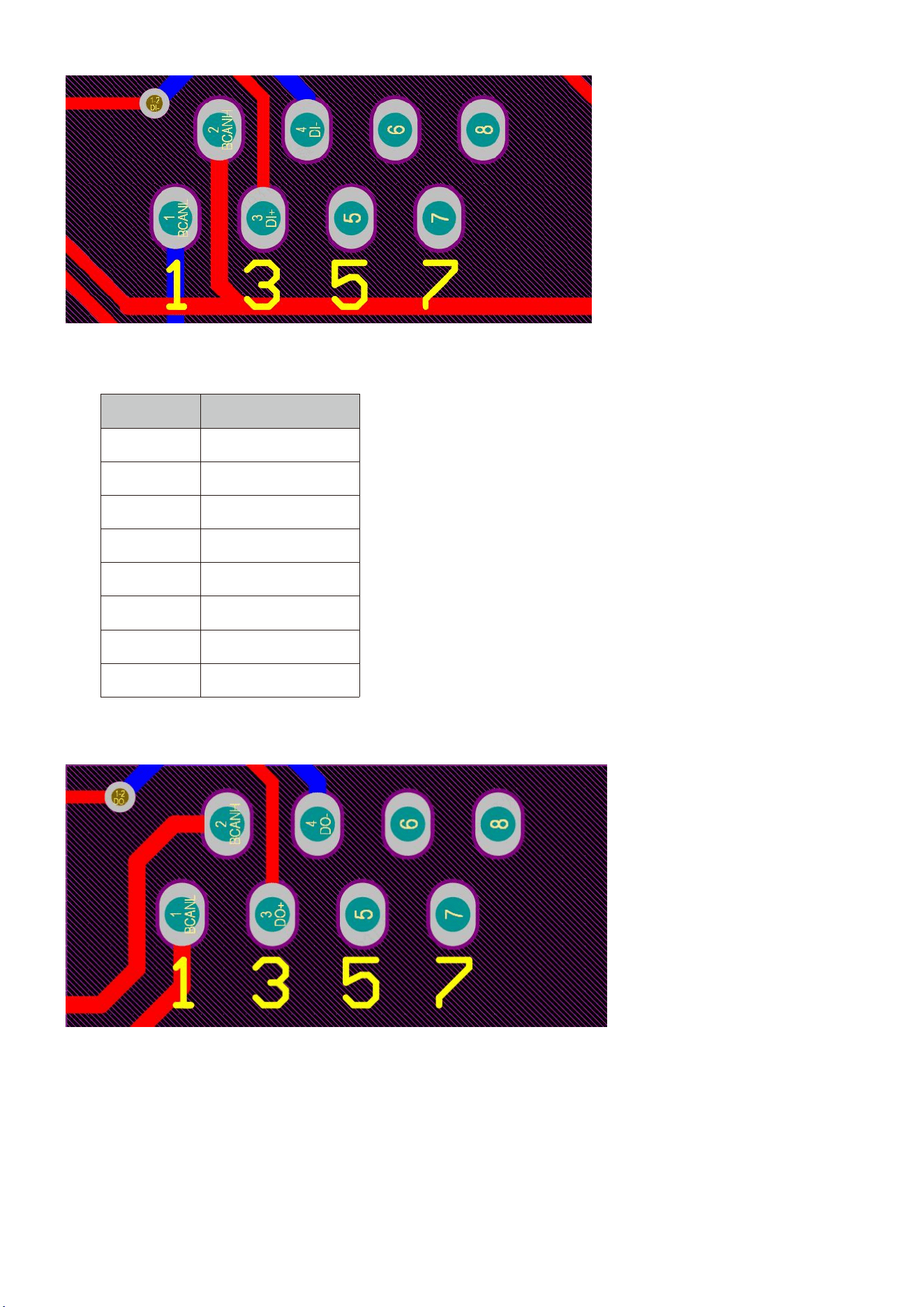
Definition of RJ45 Port Pin for parallel 2.
No.
parallel 2Pin
1
SYNC
2
AGND
3
BINGLIAH-H
4
BINGLIAH-H
5
BINGLIAH-L
6
BINGLIAH-L
7
SYNC
8
AGND
Definition of RJ45 Port Pin for parallel 2.
Definition of RJ45 Port Pin for DI.
No.
DI Pin
1
CAN-L
2
CAN-H
3
DI+
4
DI-
5
6
7
8
18
DI Port
Definition of RJ45 Port Pin for DO
No.
DOPin
1
CAN-L
2
CAN-H
3
DO+
4
DO-
5
6
7
8
DO Port

19
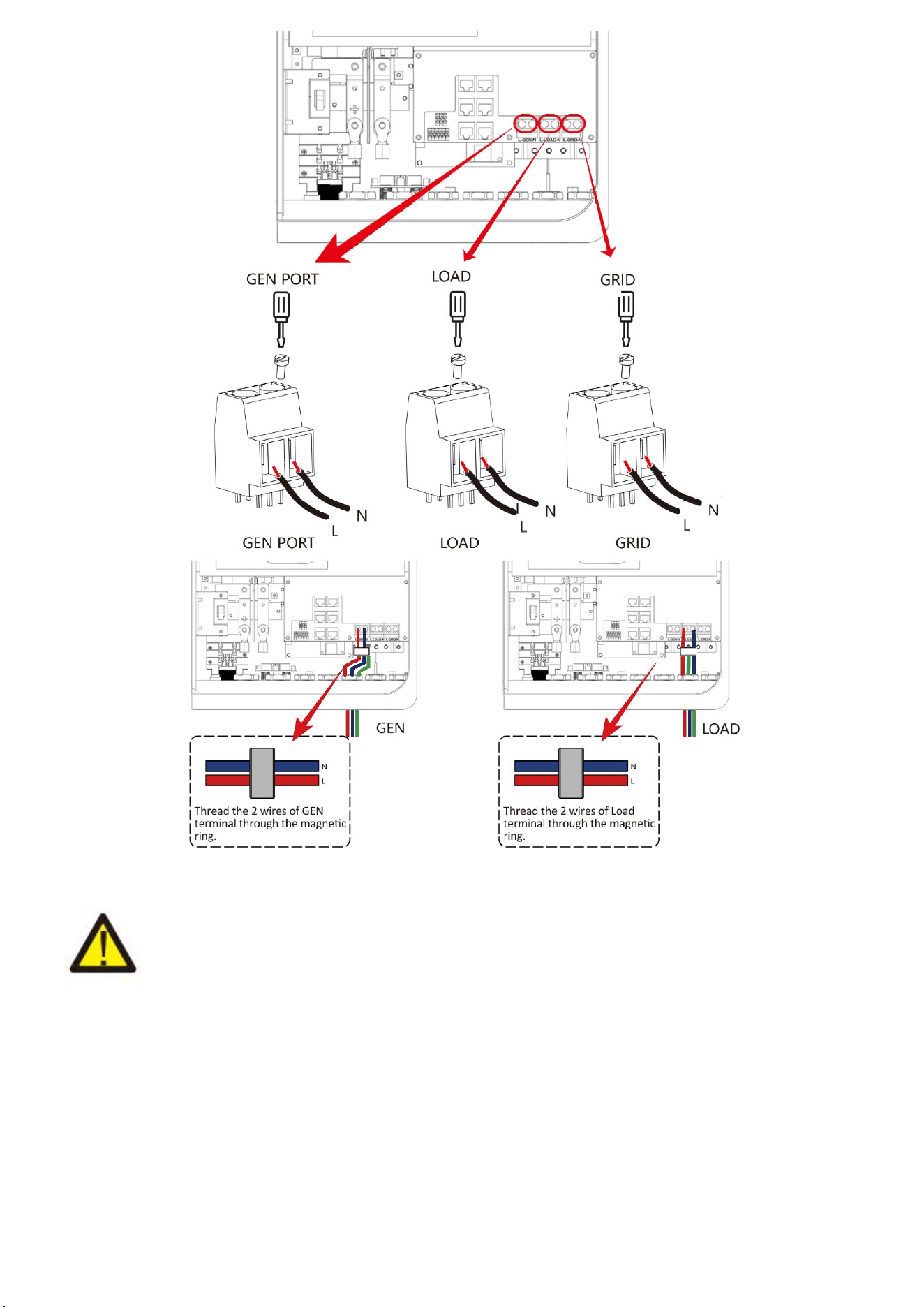
8.4 Grid connection and backup load connection
Before connecting to the grid, a separate AC breaker must be installed between the inverter and the
grid, and also between the backup load and the inverter.This will ensure the inverter can be securely
disconnected during maintenance and fully protected from over current. For the 3.6kW model, the
recommended Ac breaker for backup load 3.6/5kw is40A. For the 3.6/5kW model, the recommended
Ac breaker for grid 3.6/5kw is 40A.
There are three terminal blocks with "Grid" "Load"and "GEN" markings. Please do not misconnect
input and output connectors.
Note:
In final installation,breaker certified according to lEC 60947-1 and lEC 60947-2shall be installed with
the equipment.
All wiring must be performed by a qualified personnel.lt is very important for system safety and
efficient operation to use appropriate cable for AC input connection. To reduce risk of injury, please
use the proper recommended cable as below.
Grid connection and backup load connection (Copper wires)
Model
Wire Size
Cable(mm
2)
Torque Value (max)
3.6/5kW
8AWG
6.0
1.2Nm
Grid connection and backup load connection (Copper wires) (Bypass)
Model
Wire Size
Cable(mm
2)
Torque Value (max)
3.6/5kW
8AWG
6
1.2Nm
Chart 8-4-1: Recommended Size for AC wires
Please follow below steps to implement Ac input/output connection:
1. Before making Grid, load and Gen port connection, be sure to turn off Ac breaker or disconnector
first.
2. Remove insulation sleeve 10mm length, unscrew the bolts. For GRlD port, just insert the wires into
the terminals according to polarities indicated on the terminal block. for GEN and Load ports, thread
the wires through the magnetic ring firstly, then insert these wires into the terminals according to
polarities indicated on the terminal block. Tighten the terminal screws and make sure the wires are
completely and safely connected.
20
Be sure that AC power source is disconnected before attempting to wire it to the unit.
3. Then, insert AC output wires according to polarities indicated on the terminal block and tighten
terminal. Be sure to connect corresponding N wires and PE wires to related terminals as well.
4. Make sure the wires are securely connected.
5. Appliances such as air conditioner are required at least 2-3 minutes to restart because it is
required to have enough time to balance refrigerant gas inside of circuit. If a power shortage occurs
and recovers in short time, it will cause damage to your connected appliances. To prevent this kind of
damage, please check manufacturer of air conditioner if it is equipped with time-delay function before
installation. Otherwise, this inverter will trigger overload fault and cut off output to protect your
appliance but sometimes it still causes internal damage to the air conditioner.
21
8.5 PV Connection
Before connecting to PV modules, please install a separately DC circuit breaker between inverter and
PV modules. It is very important for system safety and efficient operation to use appropriate cable for
PV module connection. To reduce risk of injury, please use the proper recommended cable size as
below.
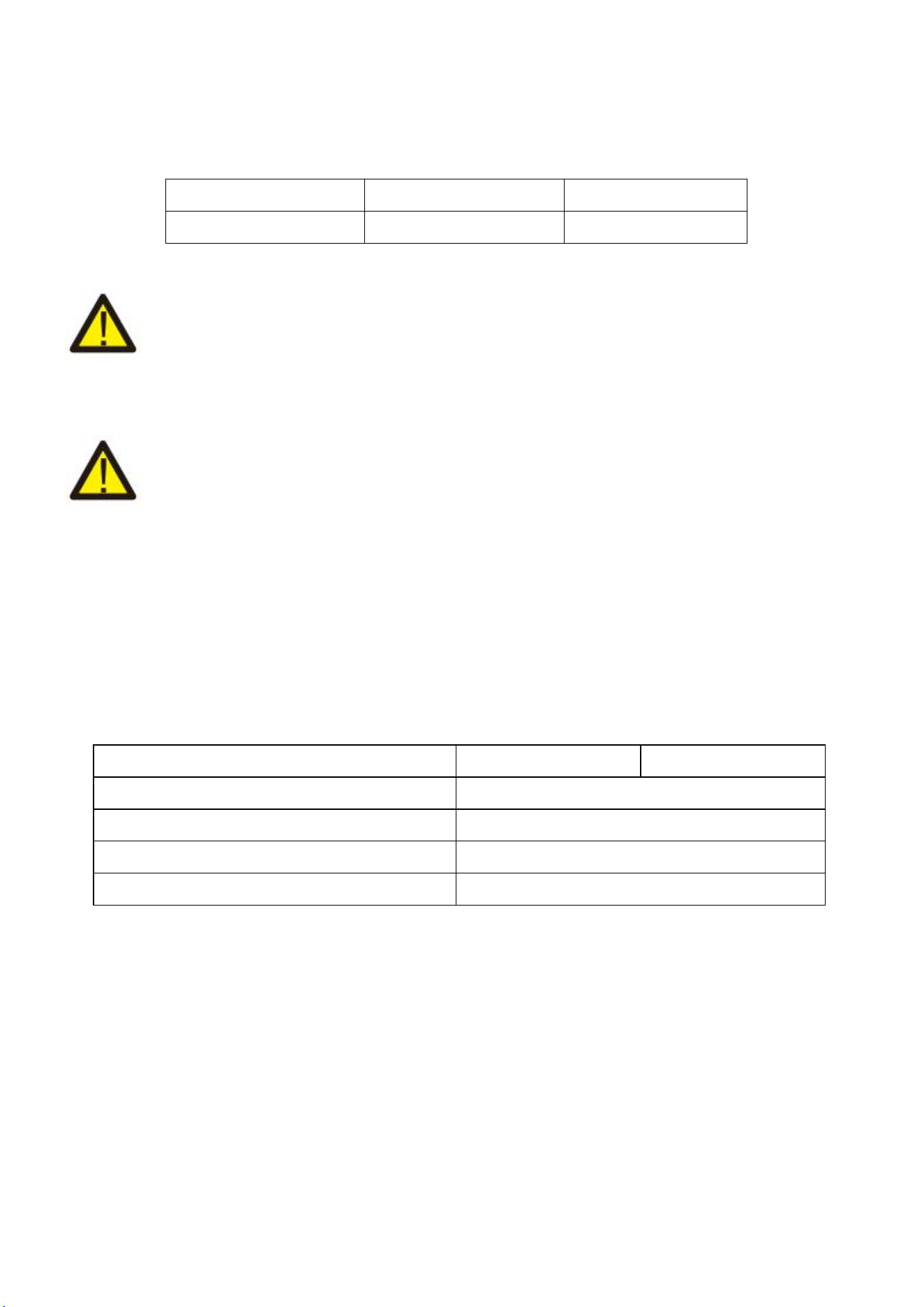
Model
Wire Size
Cable(mm
2)
3.6/5kW
12AWG
2.5
Chart 8-5-1: Cable size
To avoid any malfunction, do not connect any PV modules with possible current leakage to
the inverter. For example, grounded PV modules will cause current leakage to the inverter. When
using PV modules, please ensure the PV+ & PV- of solar panel is not connected to the system ground
bar.
It is requested to use PV junction box with surge protection. Otherwise, it will cause
damage on inverter when lightning occurs on PV modules.
8.5.1 PV Module Selection:
When selecting proper PV modules, please be sure to consider below parameters:
1) Open circuit Voltage (Voc) of PV modules not exceeds max. PV array open circuit voltage of
inverter.
2) Open circuit Voltage (Voc) of PV modules should be higher than min. start voltage.3)The PV
modules used to connected to this inverter shall be Class A rating certified according to lEC 61730.
Inverter Model
3.6kW
5kW
PV Input Voltage
370V(125V-500V)
PV Array MPPT Voltage Range
150V-425V
No.of MPP Trackers
2
No. Of Strings per MPP Tracker
1+1
Chart 8-5-2
8.5.2 PV Module Wire Connection:
1. switch the Grid supply Main switch(AC)OFF.
2. Switch the Dc lsolator OFF.
3. Assemble PV input connector to the inverter.
22
Safety Hint:
When using PV modules, please ensure the PV+ & PV- of solar panel is not connected to the system
ground bar.
Safety Hint:
Before connection, please make sure the polarity of the output voltage of PV array matches the “DC
+" and “Dc-" symbols.
Safety Hint:
Before connecting inverter, please make sure the PV array open circuit voltage is within the 500V of
the inverter.
Safety Hint:
Please use approved DC cable for PV system.
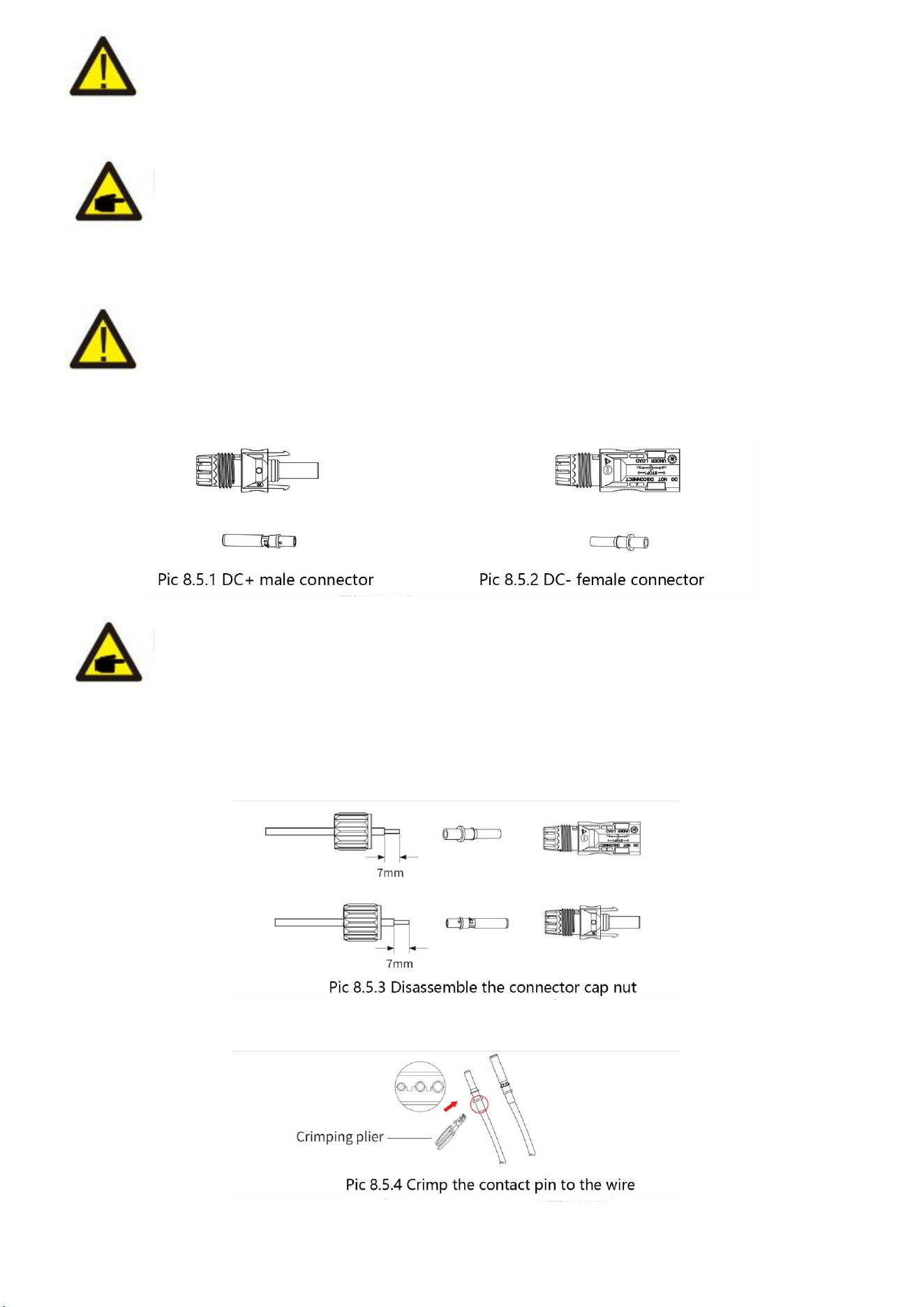
The steps to assemble the DC connectors are listed as follows:
a)Strip off the DC wire about 7mm, disassemble the connector cap nut (see picture 7.5.3).
b) Crimping metal terminals with crimping pliers as shown in picture 7.5.4.
23
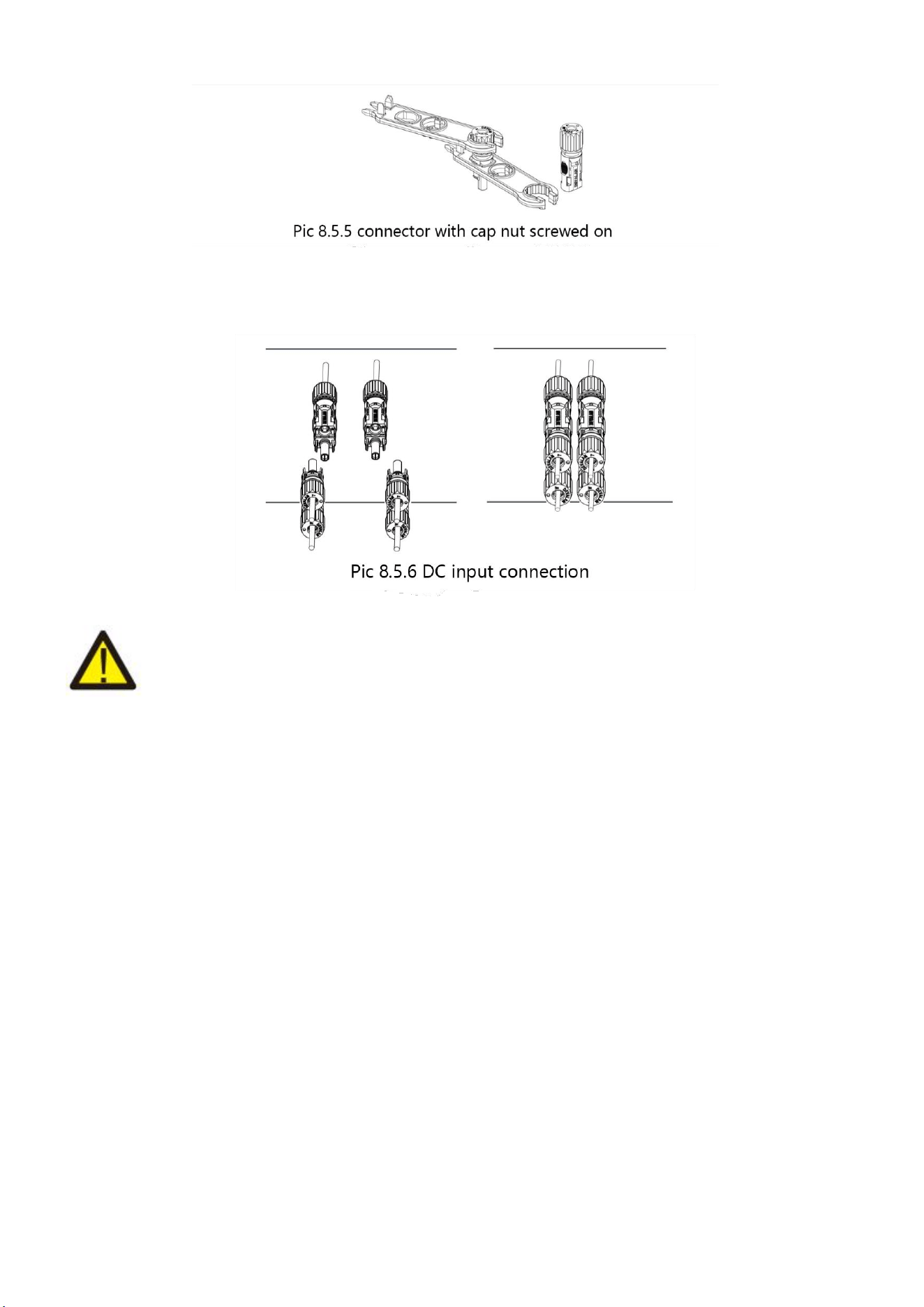
c) insert the contact pin to the top part of the connector and screw up the cap nut to the top part of
the connector.(as shown in picture 7.5.5).
d) Finally insert the DC connector into the positive and negative input of the inverter, shown as
picture 7.5.6.
Warning:
Sunlight shines on the panel will generate voltage, high voltage in series may cause danger to life.
Therefore, before connecting the DC input line, the solar panel needs to be blocked by the opaque
material and the DC switch should be OFF',otherwise, the high voltage of the inverter may lead to life-
threatening conditions.
24
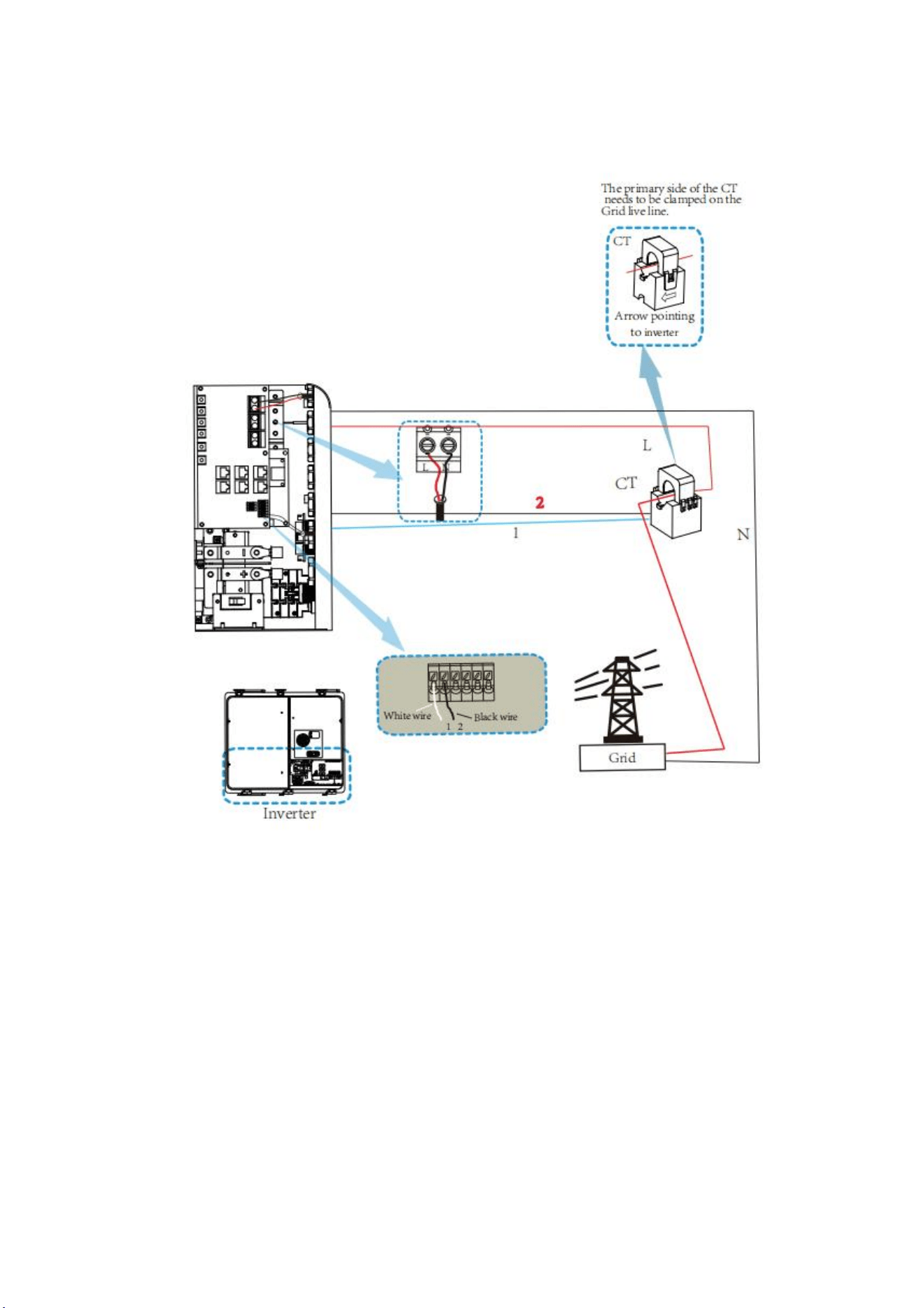
8.6 CT Connection
*Note: when the reading of the load power on the LCD is not correct, please reverse the Ct arrow.
25
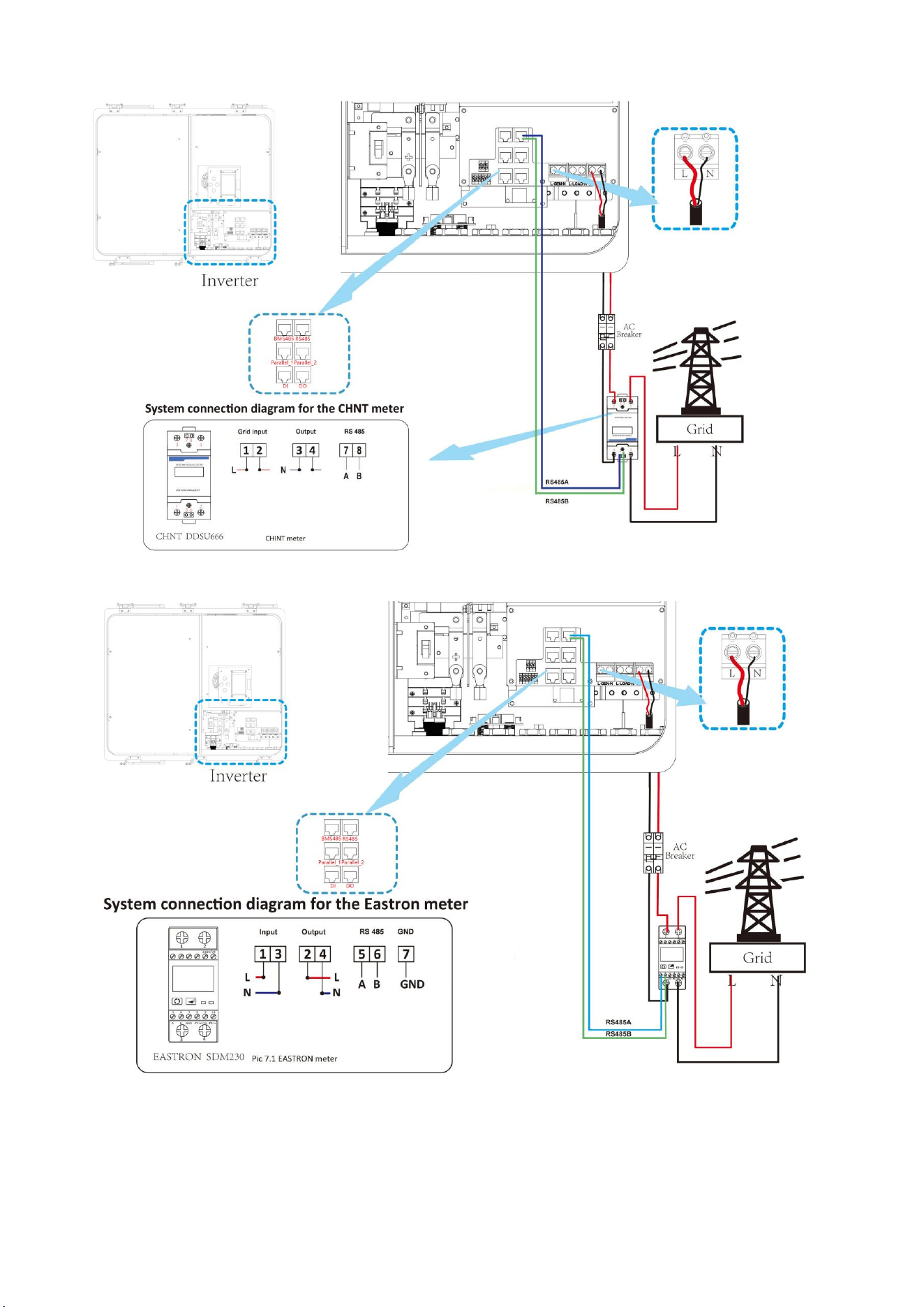
8.7 Meter Connection
26
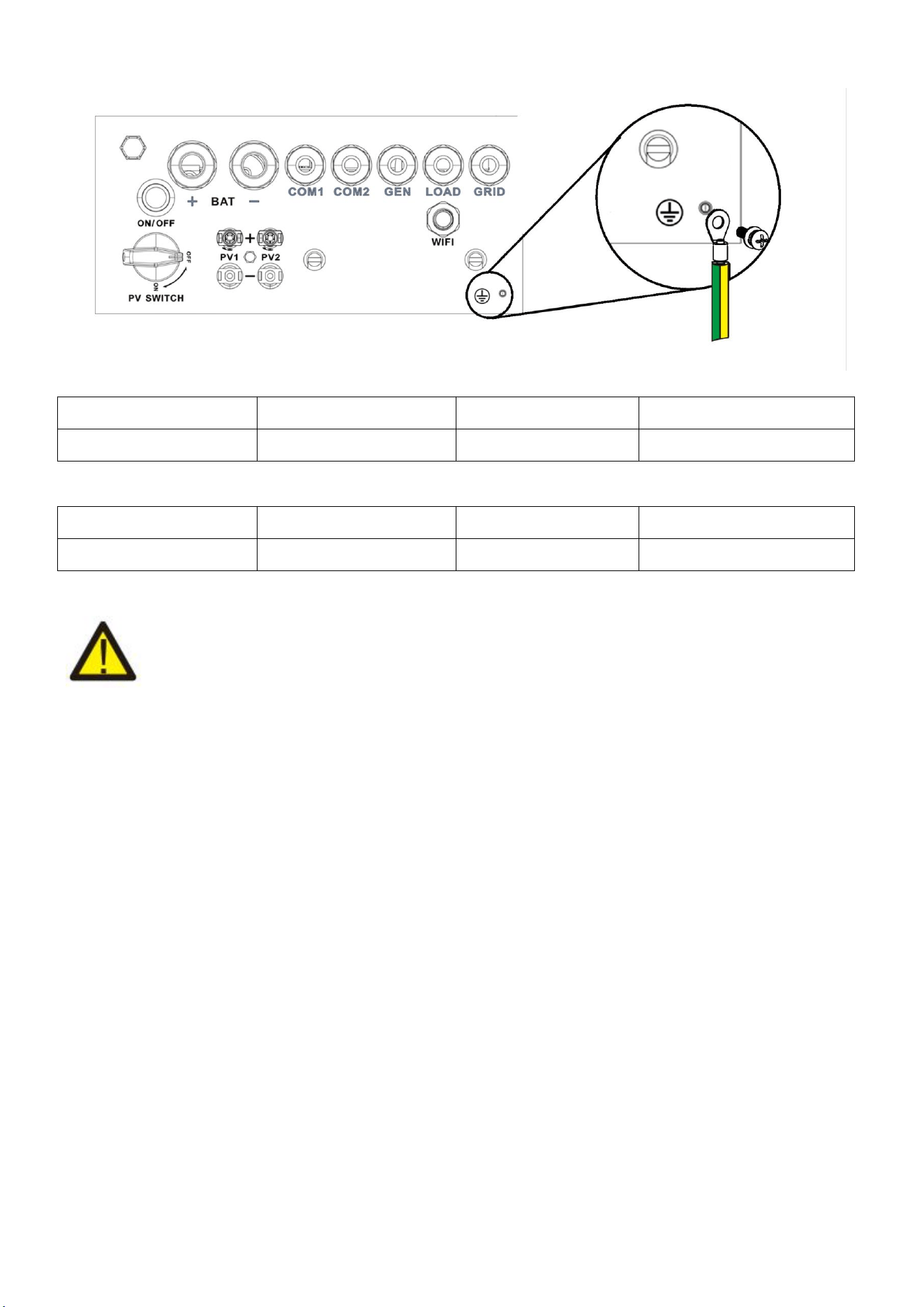
8.8 Earth Connection (mandatory)
Earth connection (Copper wires)
Model
Wire Size
Cable(mm
2)
Torque Value (max)
3.6/5kW
8AWG
6.0
1.2Nm
Earth connection (Copper Wires) (Bypass)
Model
Wire Size
Cable(mm
2)
Torque Value (max)
3.6/5kW
8AWG
6
1.2Nm
Warning:
Inverter has built-in leakage current detection circuit, The type A RCD can be connected to the
inverter for protection according to the local laws and regulations.If an external leakage current
protection device is connected, its operating current must be equal to 300 mA or higher, otherwise
inverter may not work properly.
27
9.Product Wiring Instructions
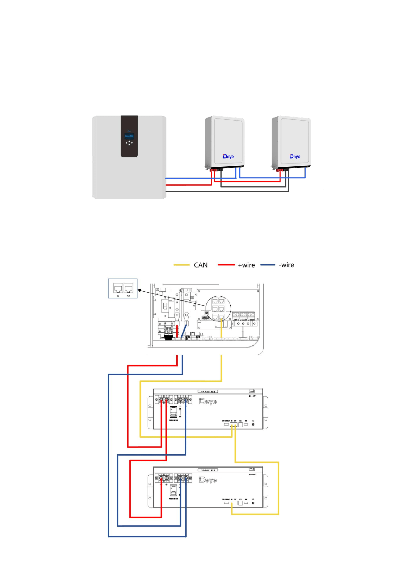
9.1 Cables for Battery Expansion
Easy to expand, support multiple parallel, support up to 16 all-in-one parallel(57.6kW/84.8kWh). At
the same time, it also supports Deye 5.3kWh battery expansion,supporting a maximum of 31 battery
packs in parallel with a maximum capacity of 169kWh.
Blue is the network cable, red is the positive electrode, and black is the negative electrode.
9.2 Parallel Capacity Expansion
28
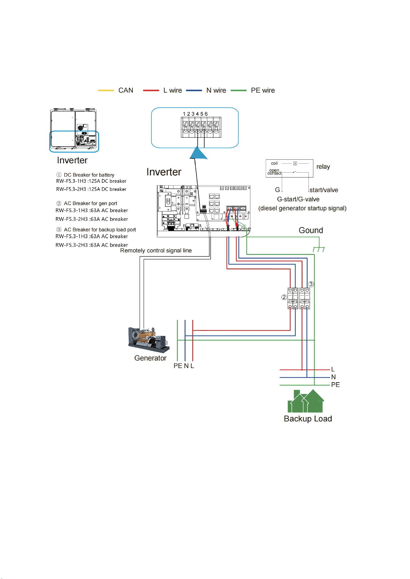
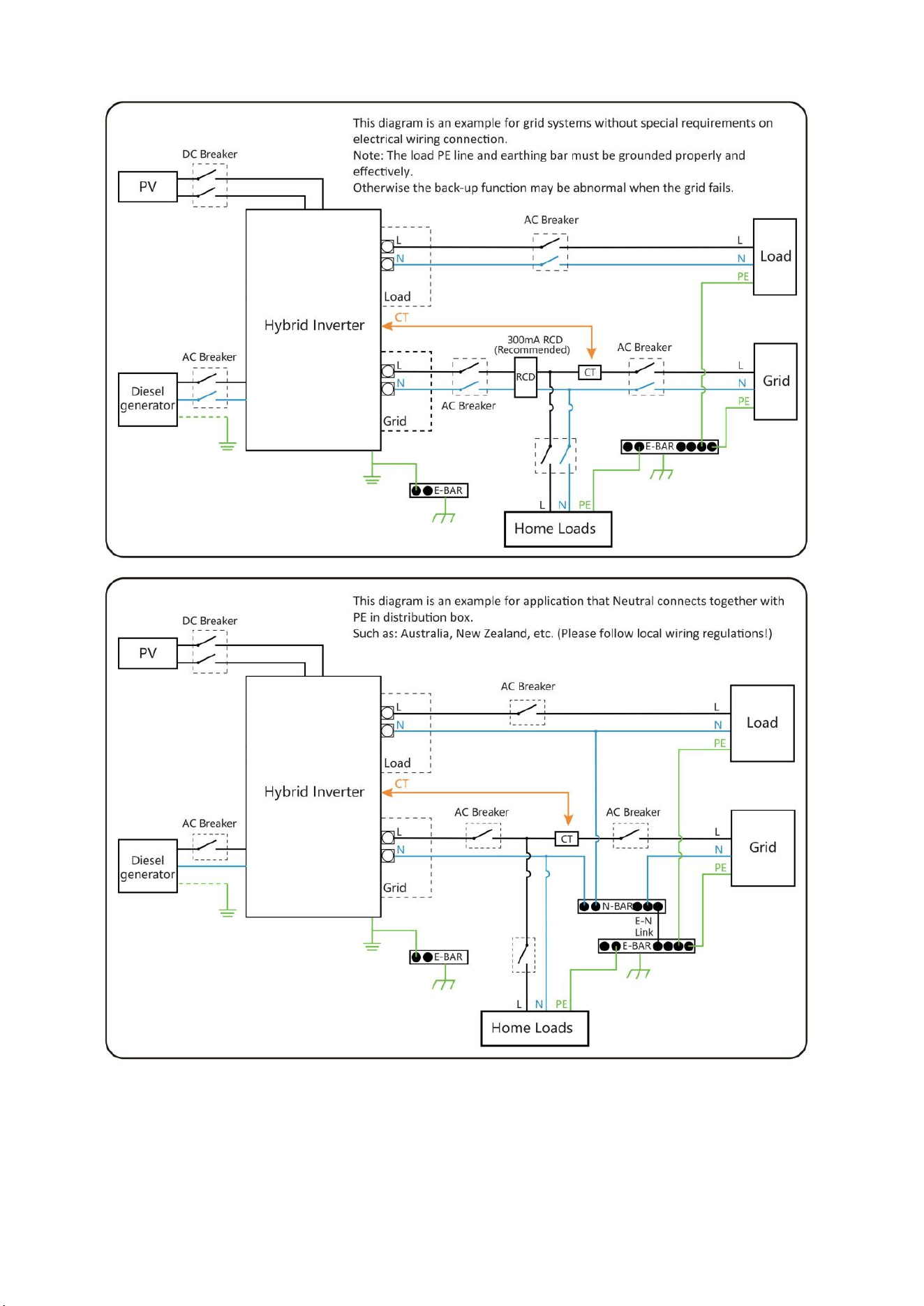
9.3 Typical Application Diagram of Diesel Generator
29
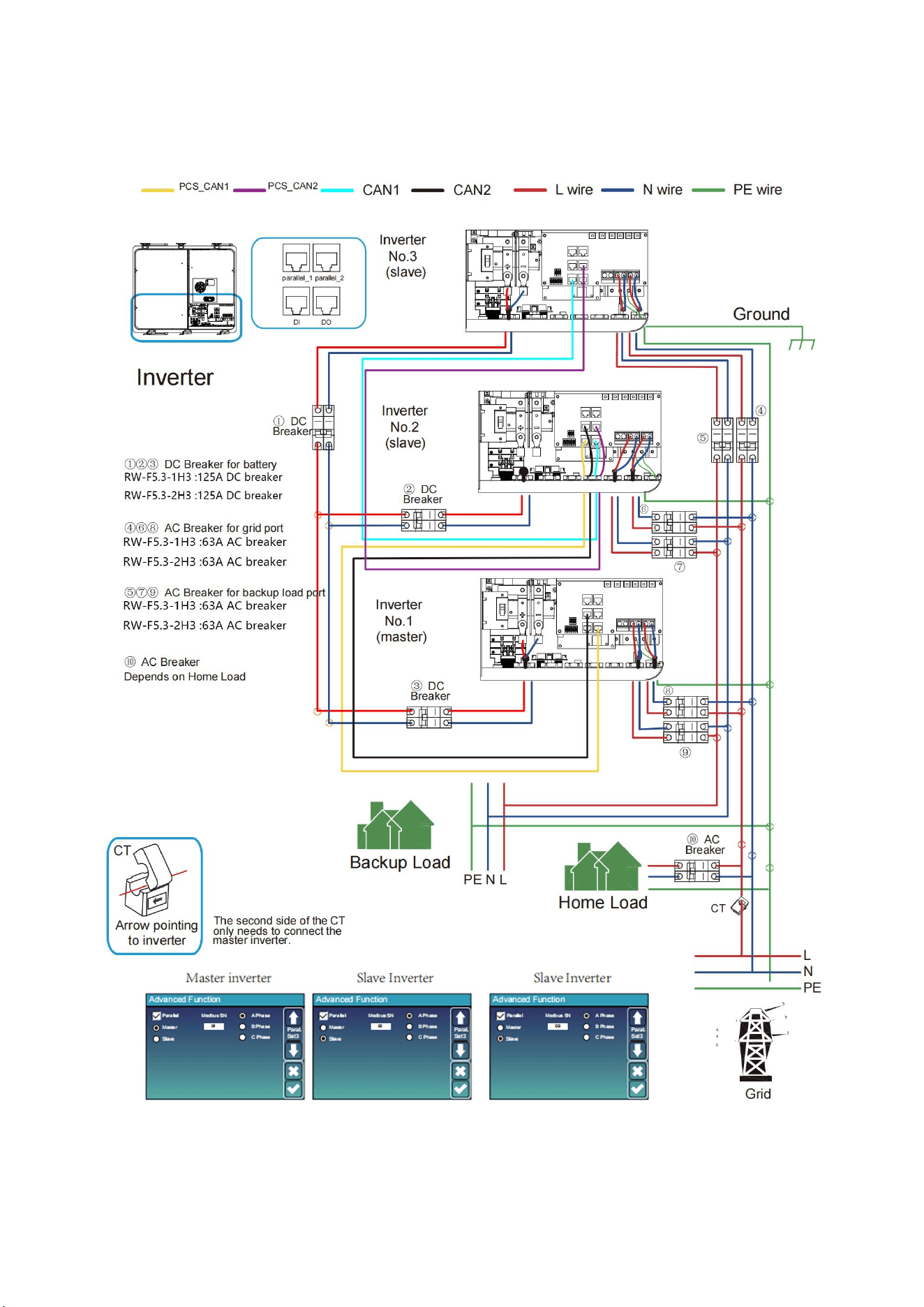
9.4 Single Phase Parallel Connection Diagram
30
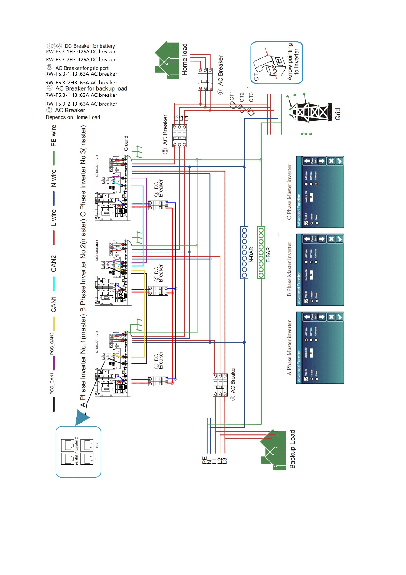
9.5 Three Phase Parallel Inverter
31
9.6 Wiring System for Inverter

32
10.Activation product
A. Hang the battery on the wall as shown on 8.2.
B. Connect the wires according to the picture on 8.
C. Unscrew the fixing buckle screw, open the buckle, and Open the cover cover,open the Air Switch
first, and Close the lid,and Buckle up the buckle,and Tighten the fixing buckle screw,and then
turn on the Power Button to prevent battery short-circuit protection
failure caused by the pre-charge function.
Start the Battery:
After installation, wiring, and configuration are completed, you must check all the connection. When
the connections are correctly, and then press power button to activate the battery. The green working
light on of the integrated machine flashes,the display screen lights up, indicating that the battery
system is normal.
33
11.LCD Display Icons
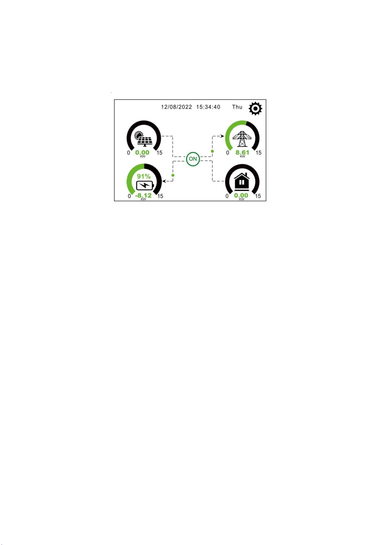
11.1 Main Screen
The LCD is touchscreen, below screen shows the overall information of the inverter.
1.The icon in the center of the home screen indicates that the system is Normal operation. If it turns
into "comm./F01~F64" , it means the inverter has communication errors or other errors, the error
message will display under this icon(F01-F64 errors, detail error info can be viewed in the System
Alarms menu).
2.At the top of the screen is the time.
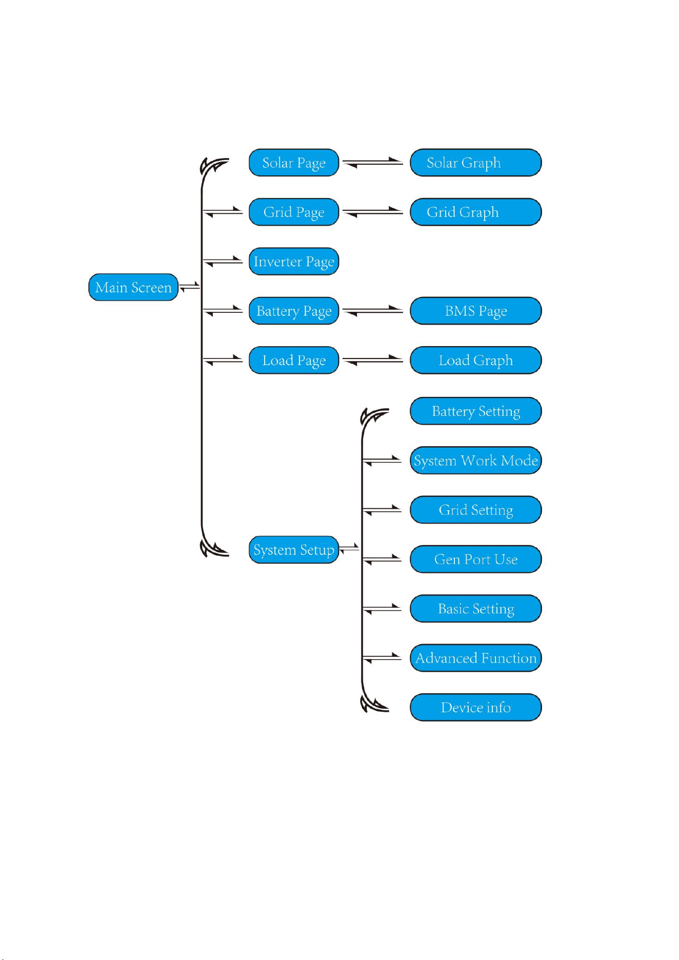
3.System Setup Icon, Press this set button, you can enter into the system setup screen which
including Basic Setup, Battery Setup, Grid Setup, System Work Mode, Generator port use, Advanced
function and Li-Batt info.
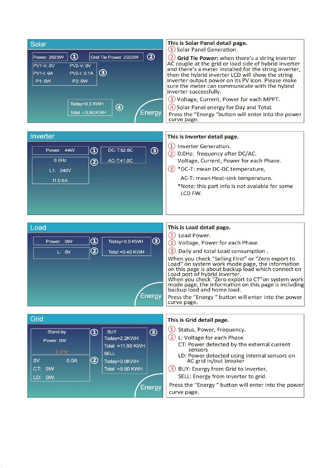
4.The main screen showing the info including Solar, Grid, Load and Battery. Its also displaying the
energy flow direction by arrow. When the power is approximate to high level, the color on the panels
will changing from green to red so system info showing vividly on the main screen.
·
PV power and Load power always keep positive.
·
Grid power negative means sell to grid, positive means get from grid.
· Battery power negative means charge, positive means discharge.
34
11.1.1 LCD Operation Flow Chart
35
11.2 Solar Power Curve
36
11.2 Curve Page-Solar & Load & Grid
37
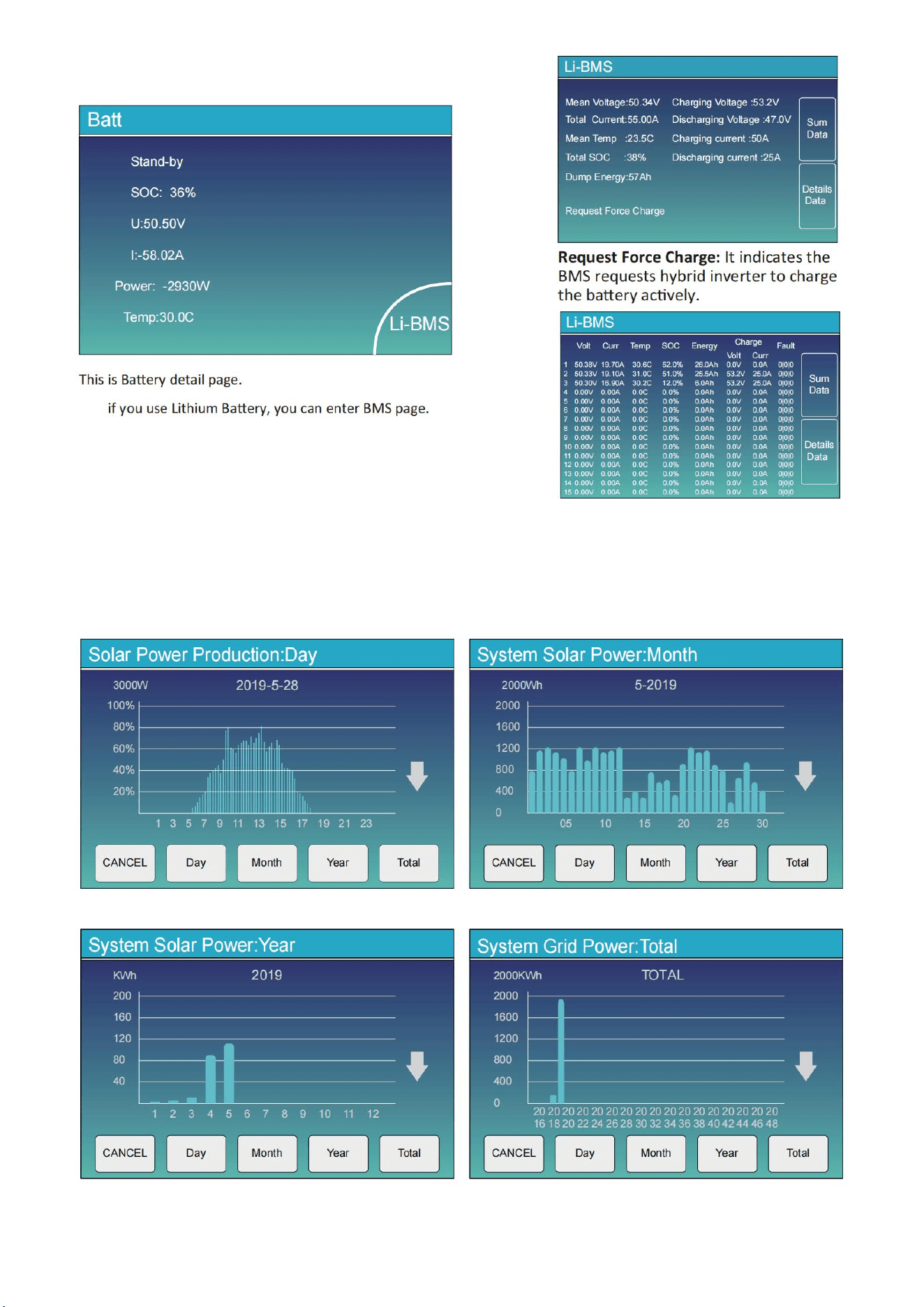
Solar power curve for daily, monthly, yearly and total can be roughly checked on the LCD, for more
accuracy power generation, pls check on the monitoring system. Click the up and down arrow to check
power curve of different period.
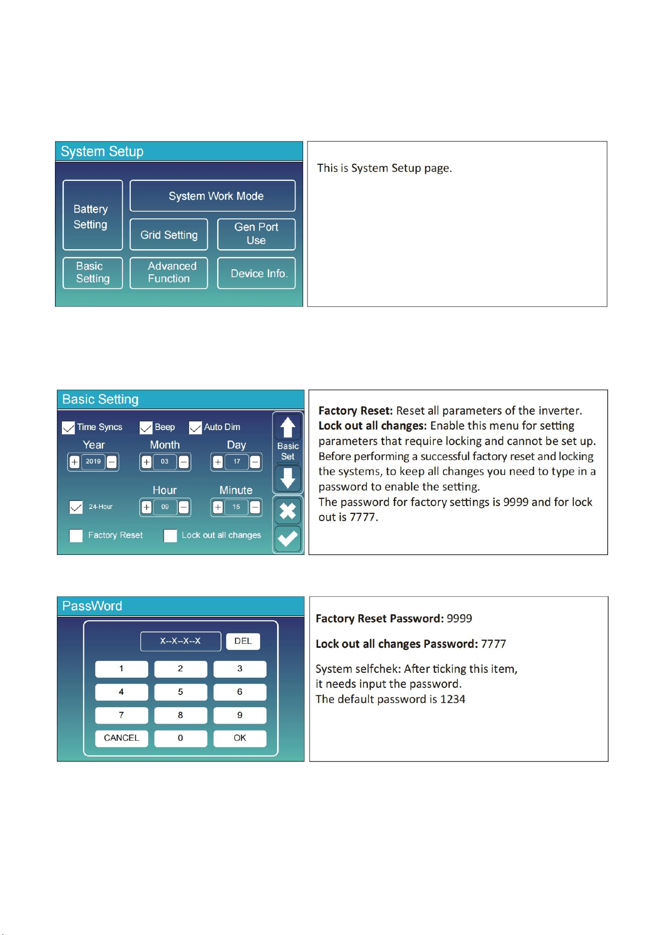
11.3 System Setup Menu
11.4 Basic Setup Menu
38
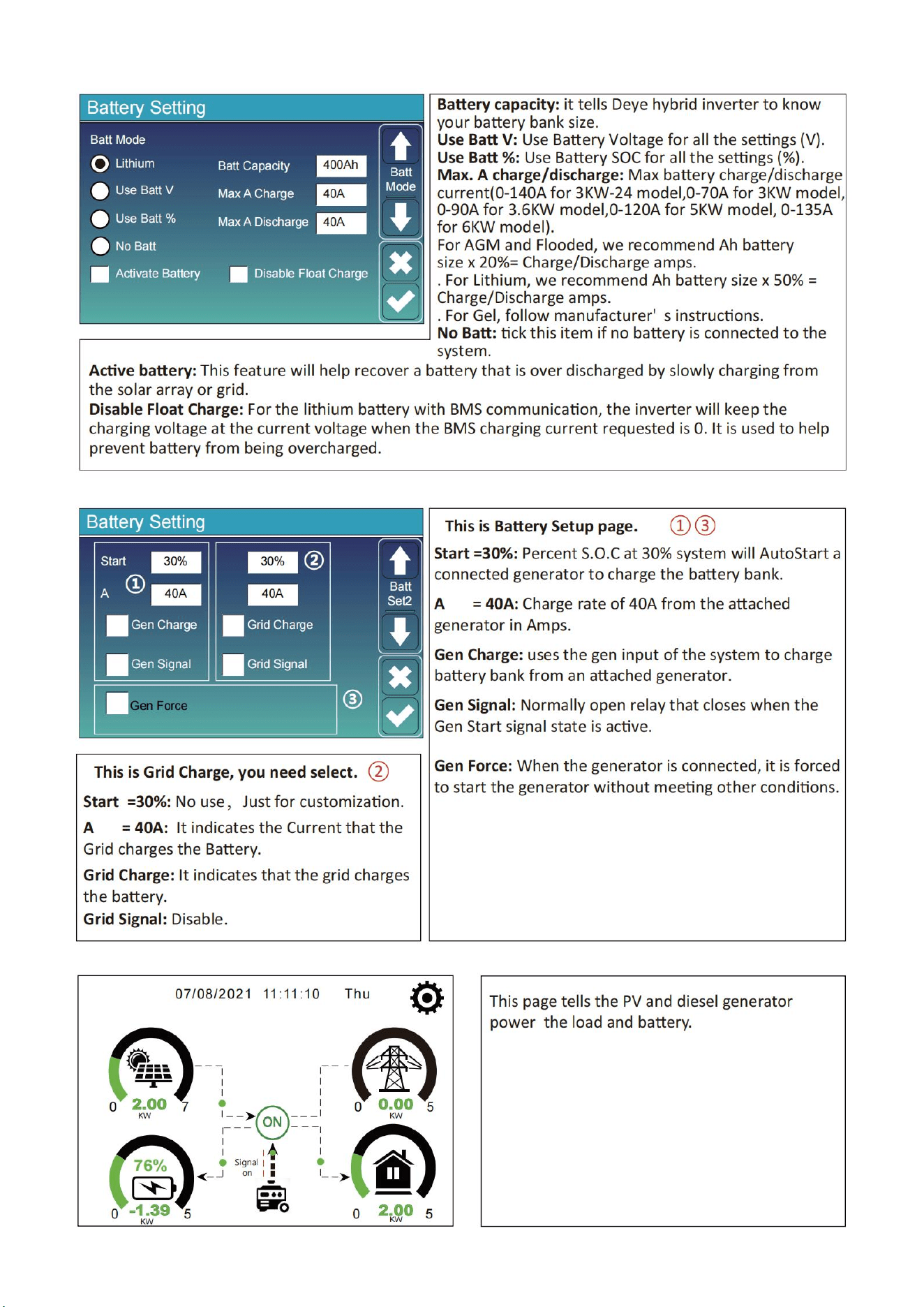
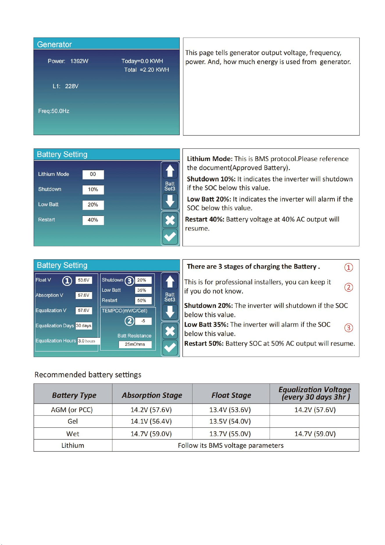
11.5 Battery Setup Menu
39
40
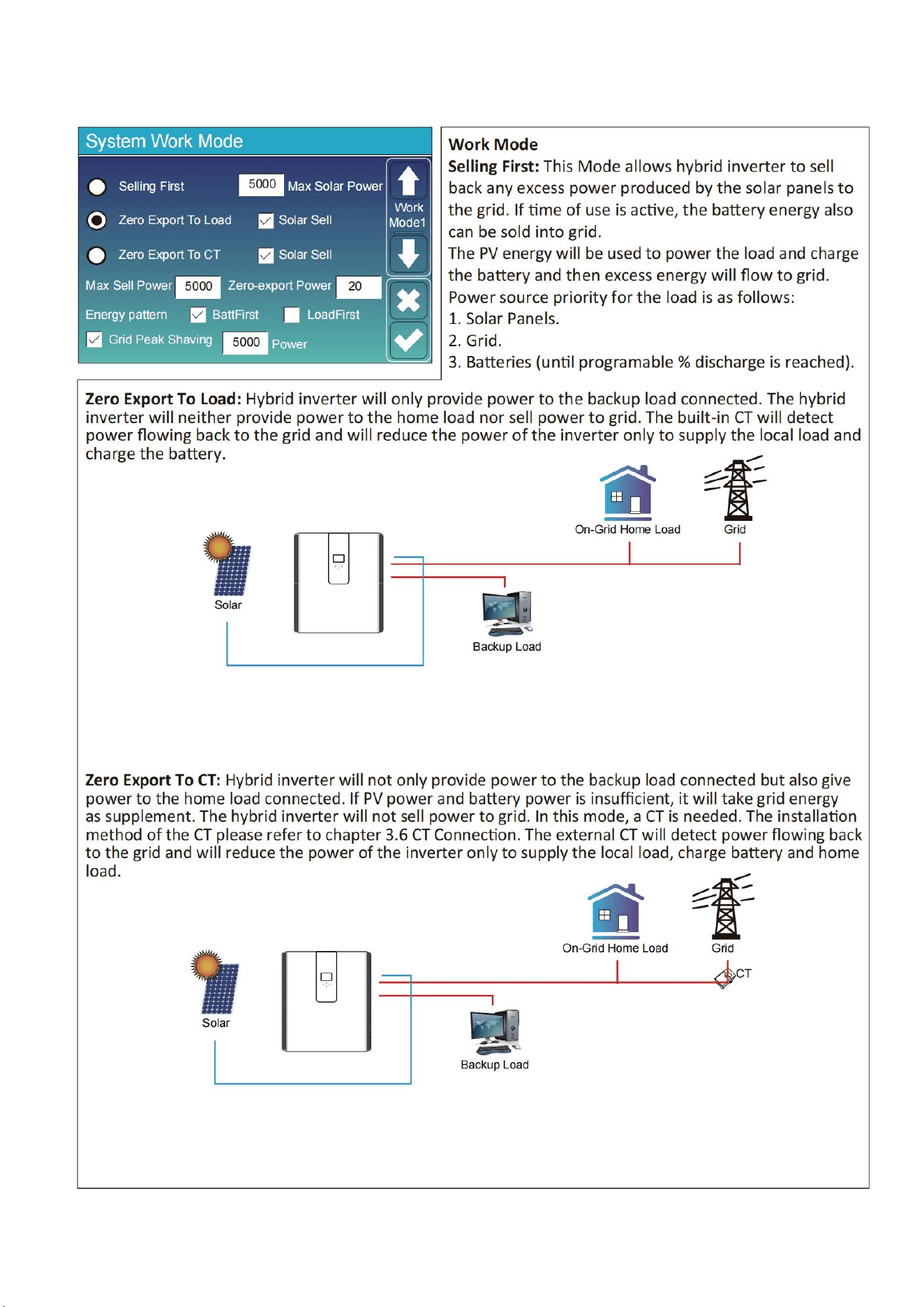
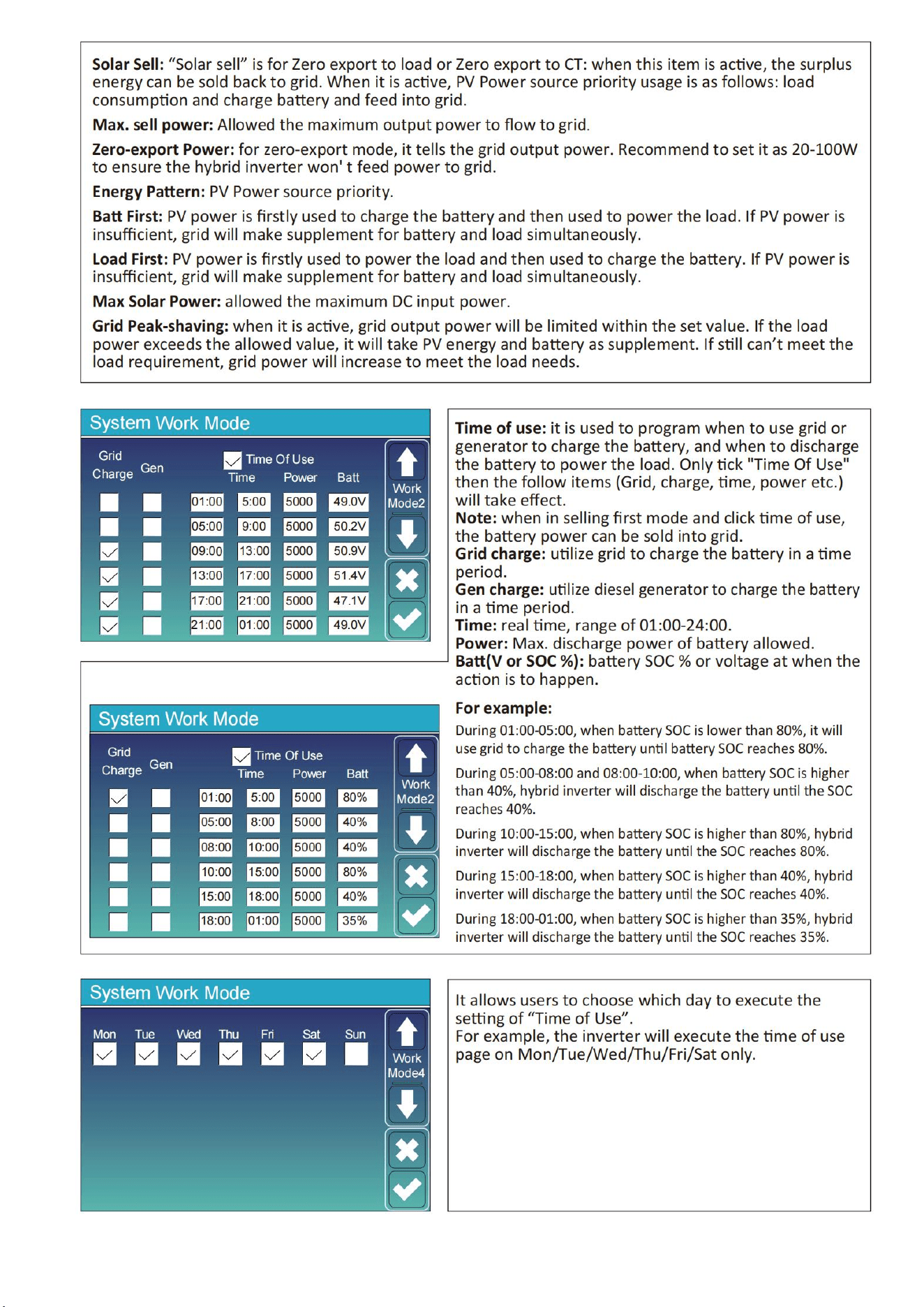
11.6 System Work Mode Setup Menu
41
42
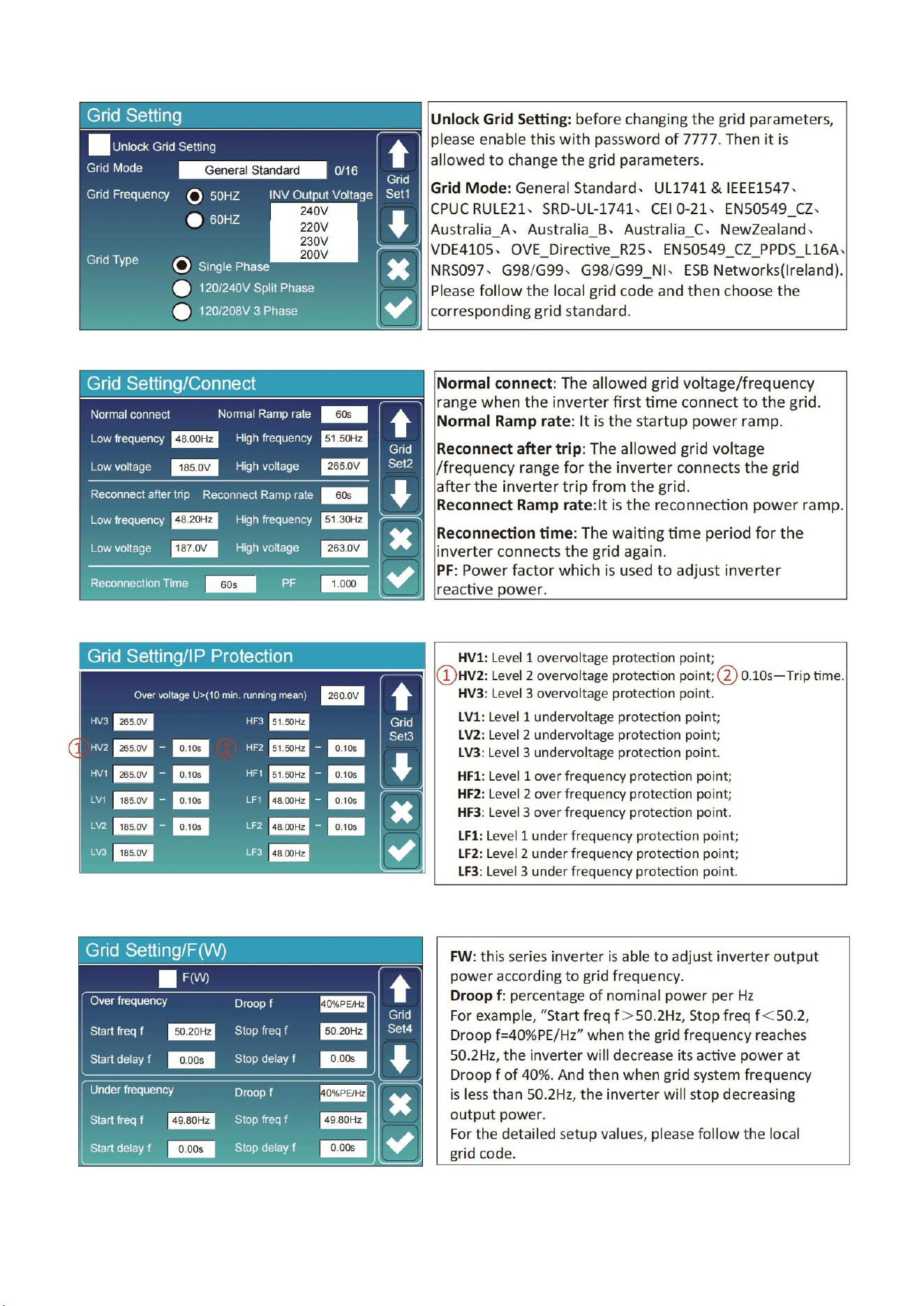
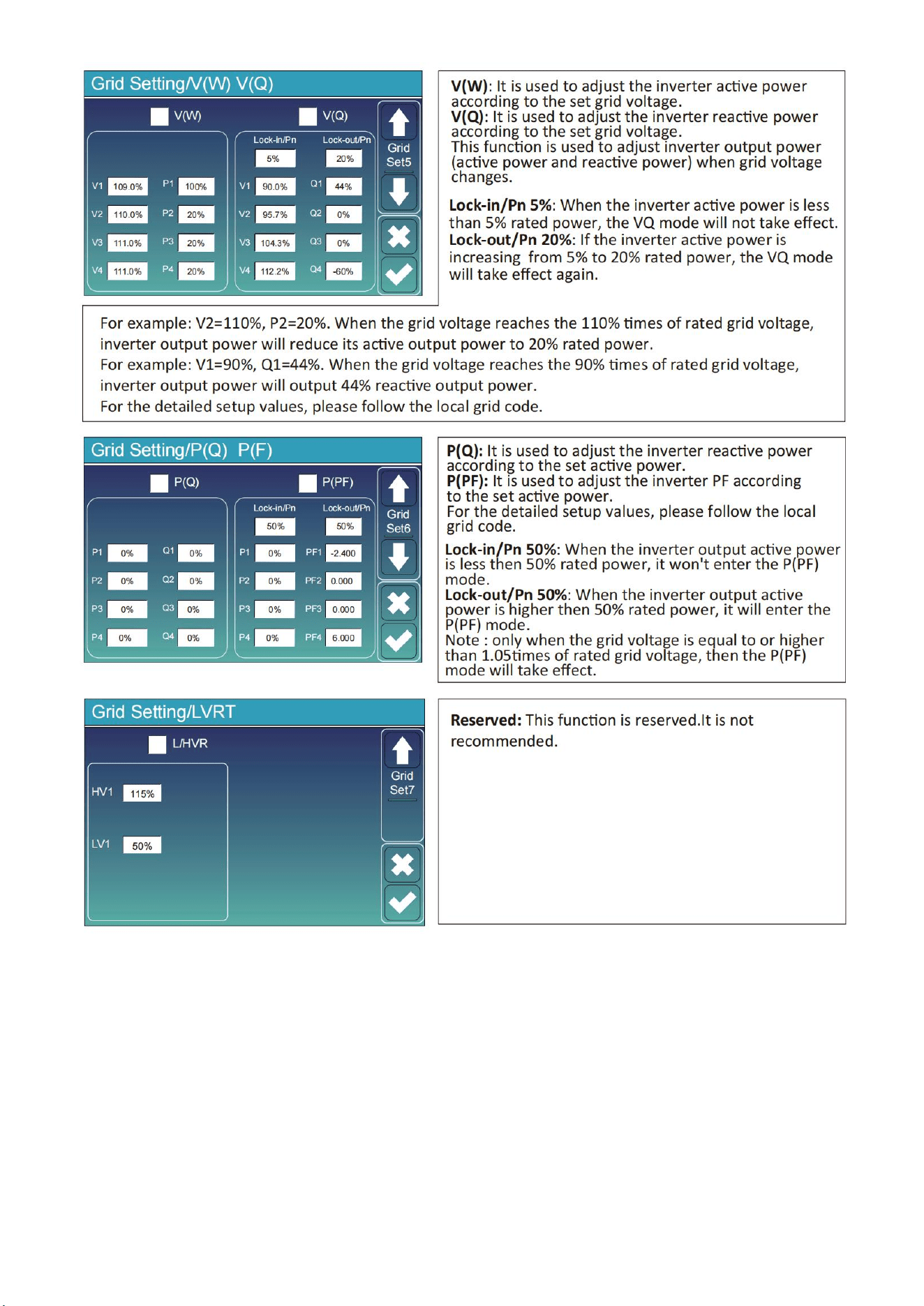
11.7 Grid Setup Menu
43
44
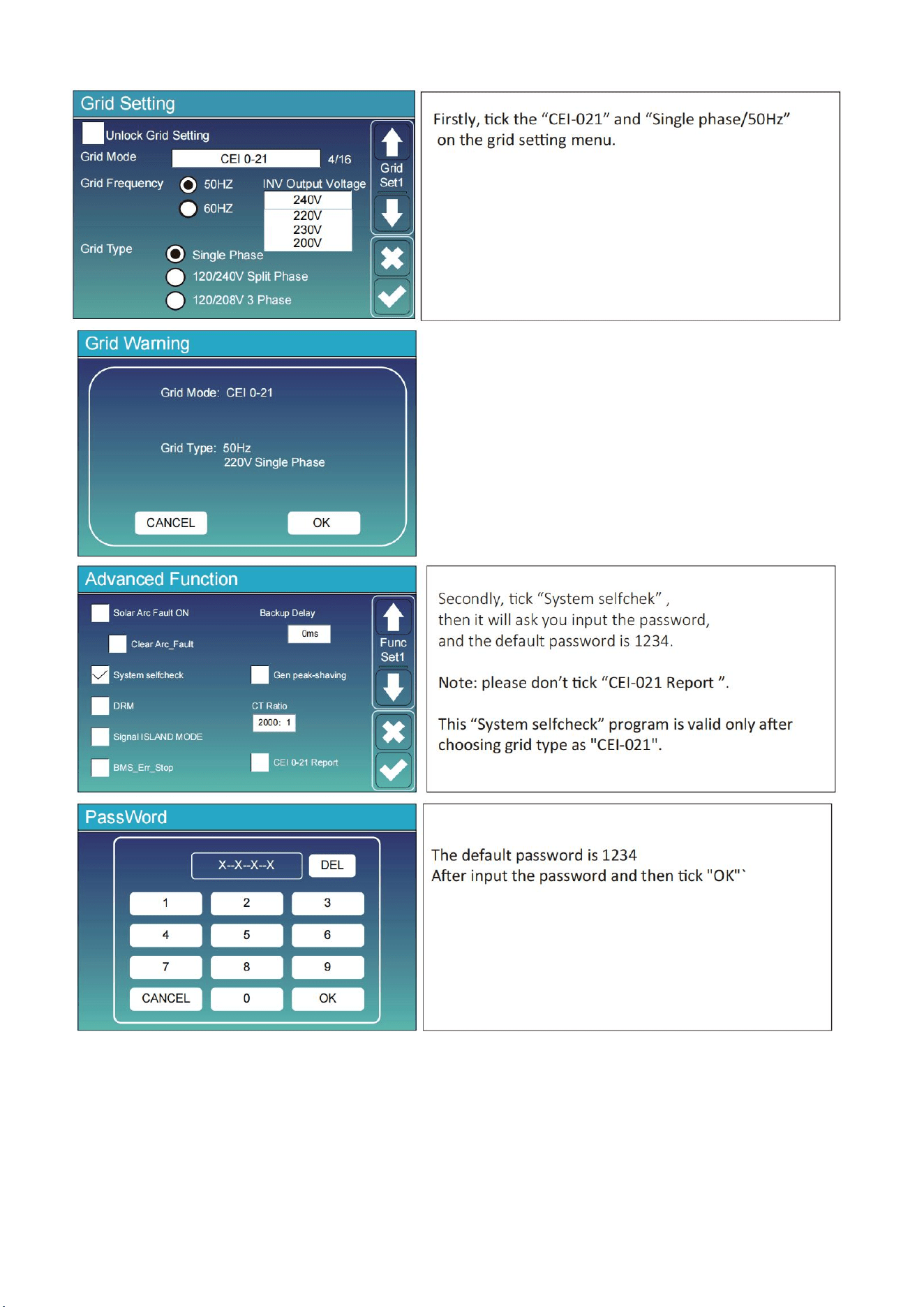
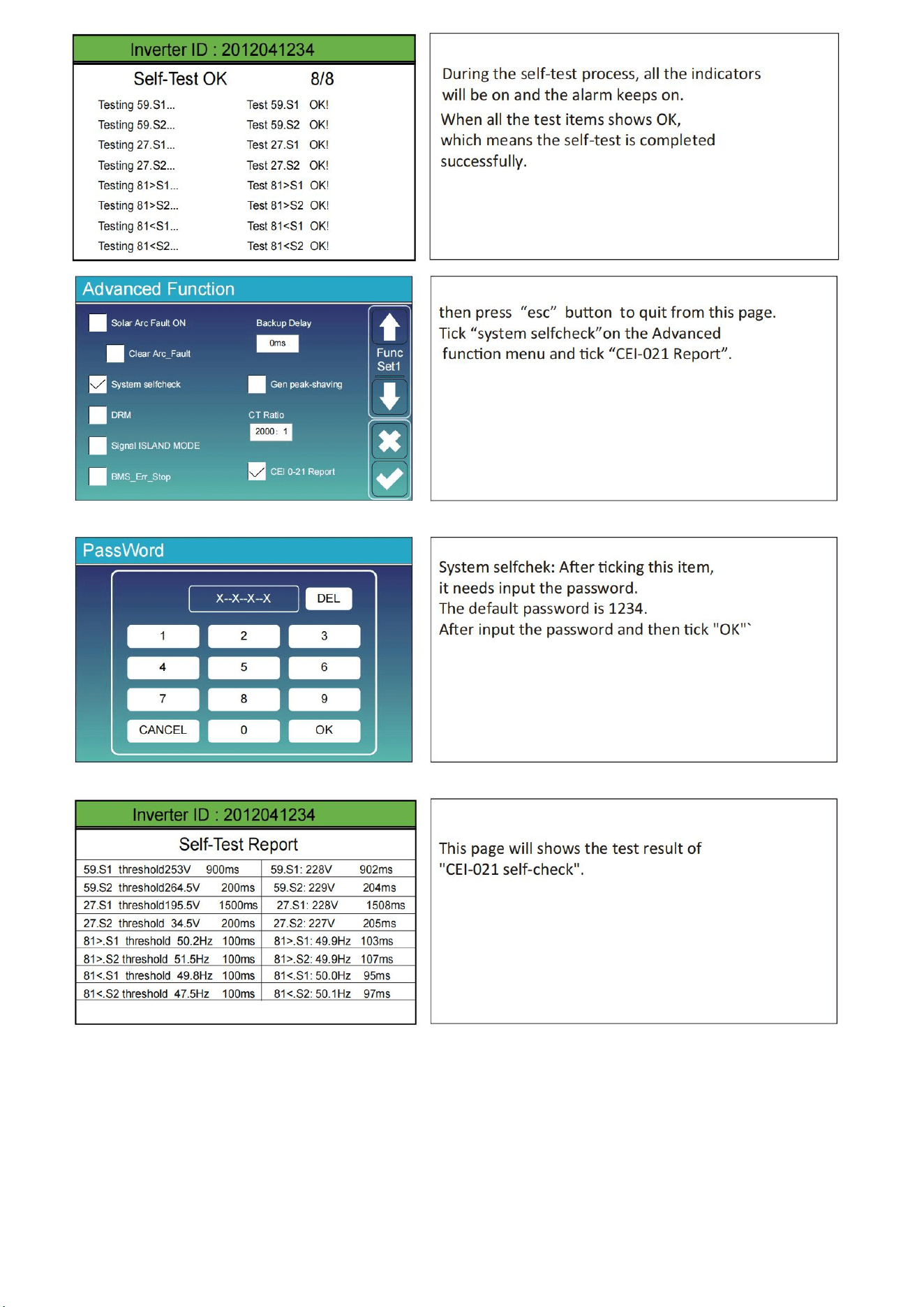
11.8 The Method of CEI-021 Standard Self-Check
45
46
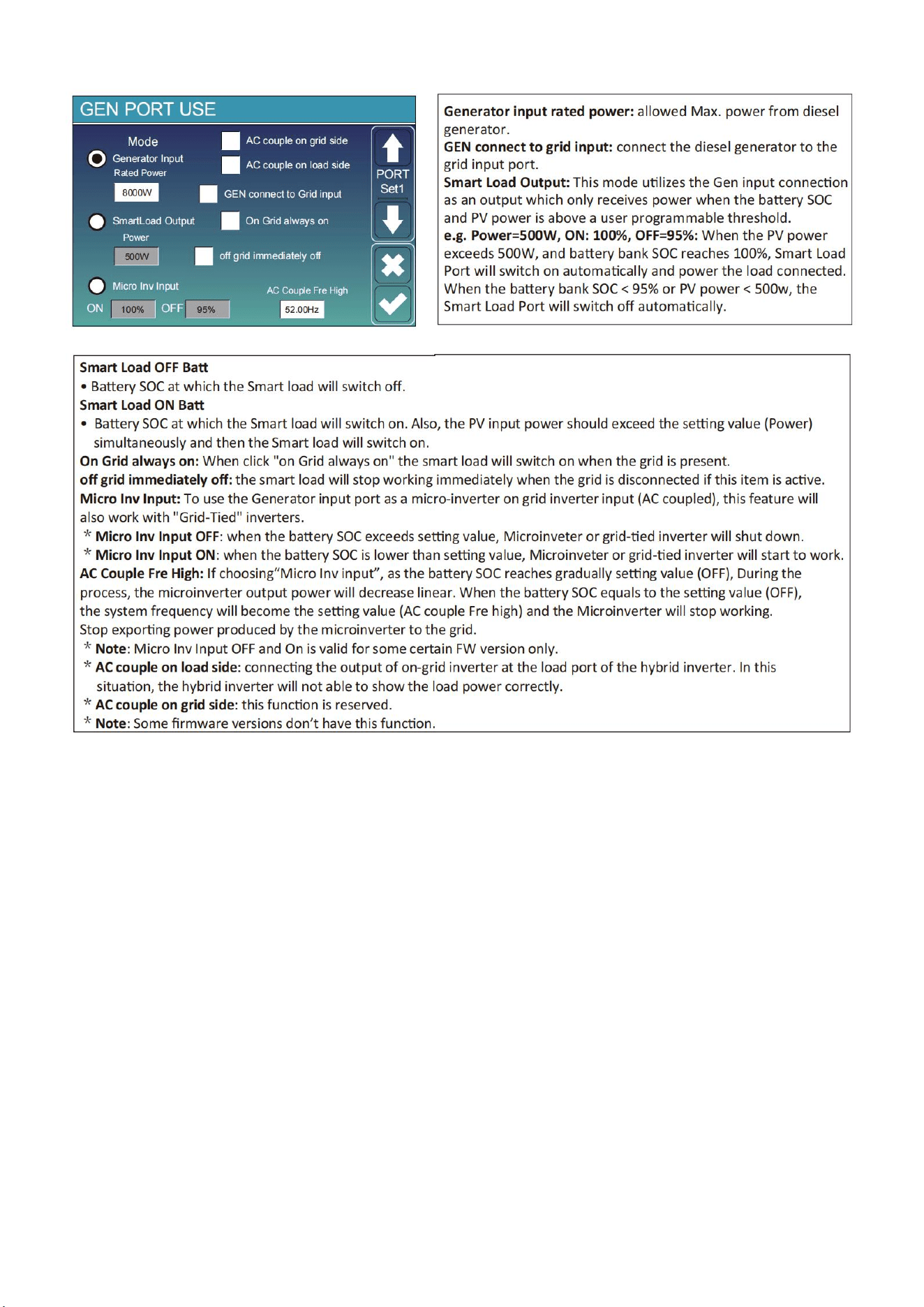
11.9 Generator Port Use Setup Menu
47
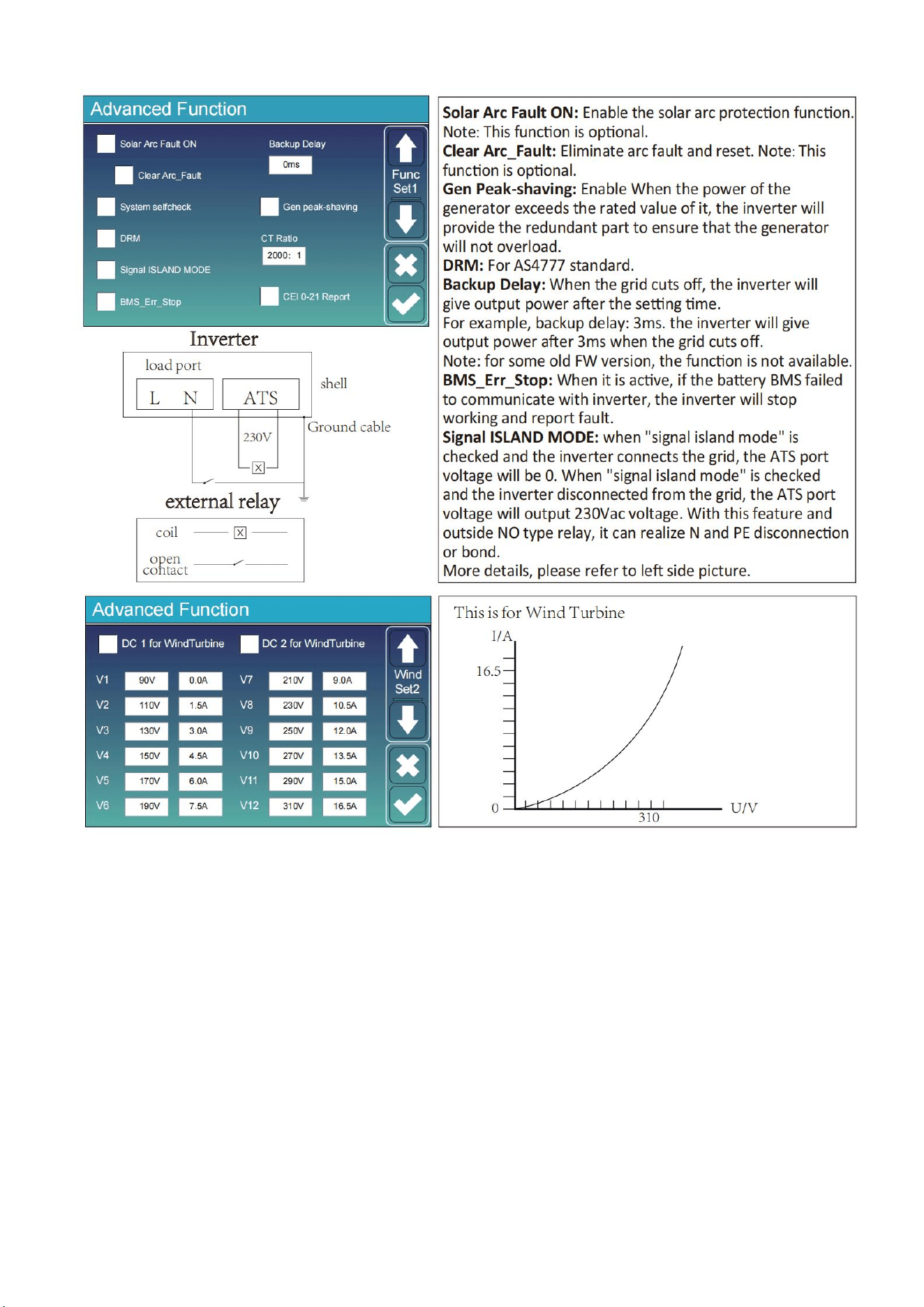
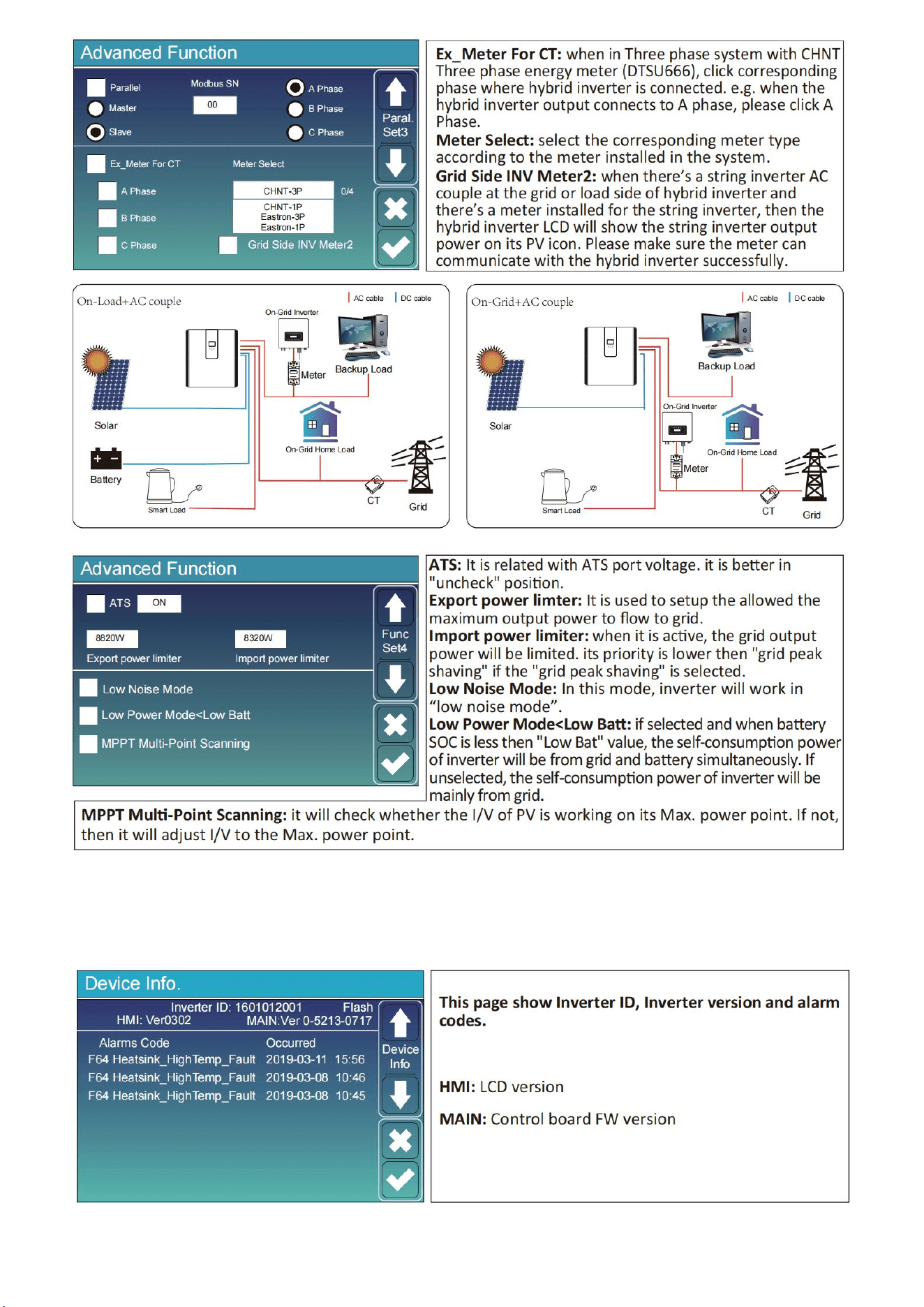
11.10 Advanced Function Setup Menu
48
11.11 Device Info Setup Menu

49
12.Fault Content
12.1 Fault Information and Processing
The energy storage inverter is designed according to the grid-connected operation standard and
meets the safety requirements and electromagnetic compatibility requirements. Before leaving the
factory, the inverter undergoes several rigorous tests to ensure that the inverter can operate reliably.
If any of the fault messages listed in Chart12-1 appear on your inverter and
the fault has not been removed after restarting, please contact your local
dealer or service center. you need to have the following information ready.
1. Inverter serial number;
2. Distributor or service center of the inverter ;
3. on-grid power generation date;
4. The problem description (including the fault code and indicator status displayed on the LCD) is as
detailed as possible.
5. your contact information. In order to give you a clearer understanding of the inverter's fault
information, we will list all possible fault code sand their descriptions when the inverter is not
working properly.
12.2 Low Voltage Fault Analysis Method
The cloud platform or LCD displays the hexadecimal value of the original fault. Each Bit indicates a
fault. 1 indicates yes and 0 indicates none.
0x0000 0x0000
0x0000 0x0000
The preceding data corresponds to CAN packets in the PCS CAN communication protocol.
Corresponding CAN packet:
byte0、1 byte2、3
byte4、5 byte6、7
For example, parsing red fonts fails and converting them to binary
That is: byte0: bit7 bit6 bit5 bit4 bit3 bit2 bit1 bit0
Bit7 Bit6 Bit5 Bit4 Bit Bit2 Bit1 Bit0
Cell under
temperature
(Charge)
(Errcode:8)
temperature
DischargCell over
(Charge)
(Errcode:7)
e
Over
Current
(Errcode:6)
Charge over
Current
(Errcode:5)
Reserve
Reserv ed
d
Cell under
voltage
Cell over
Voltag
(Errcode:2)
e
(Errcode:1)

50
Byte1: bit7 bit6 bit5 bit4 bit3 bit2 bit1 bit0
For example, parse blue font failure and convert it to binary
That is: byte2: bit7 bit6 bit5 bit4 bit3 bit2 bit1 bit0
Bit7
Bit6
Bit5
Bit4
Bit3
Bit2
Bit1
Bit0
AFE-SCDL
(Errcode:24)
Reserved
Reserved
Reserved
Reserved
AFE-
OCDL/OCD1/
OCD2
(Errcode:19)
Reserved
Reserved
Byte3: bit7 bit6 bit5 bit4 bit3 bit2 bit1 bit0
Bit7
Bit6
Bit5
Bit4
Bit3
Bit2
Bit1
Bit0
Master
Address
Repeat
(Errcode:31)
PCS
communica
tion
Fail
(Errcode:)
Internal
communicati
on
Fail
(Errcode:30)
EEPROM
error
(Errcode:29)
Mosfet short
circuit
(Errcode:28)
Temperatur
e Sampling
fail
(Errcode:27)
Cell voltage
Sampling
fail
(Errcode:26)
AFE
communication
Fail
(Errcode:25)
For example, parse the purple font failure and convert it to binary.
That is: byte4: bit7 bit6 bit5 bit4 bit3 bit2 bit1 bit0
Bit7
Bit6
Bit5
Bit4
Bit
Bit2
Bit1
Bit
0
Reserved
Reserved
Reserved
Reserved
Reserved
Reserved
Reserved
Reserved
Byte5: bit7 bit6 bit5 bit4 bit3 bit2 bit1 bit0
Bit7
Bit6
Bit
5
Bit
4
Bit3
Bit2
Bit1
Bit 0
Heat Error
(Errcode:2)
Heat Mos
Adhesion
(Errcode:1)
Reserved
Reserved
Reserved
Reserved
Reserved
Reserved
Bit7
Bit6
Bit5
Bit4
Bit3
Bit2
Bit1
Bit0
Reserved
Reserved
Heating film
over
Temperature
(Errcode:14)
Mos over
temperature
(Errcode:13)
Cell
temperature
over
Difference
(Errcode:12)
Cell voltage
over
difference
(Errcode:11)
Reserved
Reserved

51
For example, parse the green font failure and convert it to binary
That is: byte6: bit7 bit6 bit5 bit4 bit3 bit2 bit1 bit0
Bit7
Bit6
Bit5
Bit4
Bit3
Bit2
Bit1
Bit0
CHG_VOLT
_LOW
(Errcode:8)
TEMP_OPE
N_WIRE_F
AIL
(Errcode:7)
VOLT_OP
EN_WIRE_
FAIL
(Errcode:6)
FUSE Blown
(Errcode:5)
OverTermi
nalTemp
Charge
Inversed
(Errcode:4)
Pre Charge
Failed
(Errcode:3)
OverConnect
Temp
Byte7: Disable
Error
code
Description
Solutions
F08
GFDI_Relay_Failu
re
1.When inverter is in Split phase(120/240Vac)or three-phase system
(120/208Vac) system,the back up load port N line needs to connect
ground;
2.If the fault still exists,please contact us for help.
F13
Working mode
change
1.When the grid type and frequency changed it will report F13;
2.When the battery mode was changed to “No battery”mode, it will
report F13;
3.For some old FW version,it will reportF13 when the system work
mode changed;
4,Generally,it will disappear automatically when shows F13;
5.If still same,and turn off the DC switch and AC switch and wait for
one minute and then turn on the DC/AC switch;
6.Seek help from us,if can not go back to normal state.
F18
AC over current
fault of hardware
AC side over current fault
1.Please check whether the back up load power and common load
power are within the range;
2.Restart and check whether it is in normal;
3.Seek help from us,if can not go back to normal state.
F20
DC over current
fault of the
hardware
DC side over current fault
1.Check PV module connect and battery connect;
2.When in the off-grid mode,the inverter startup with big power load,it
may report F20.Please reduce the load power connected;
3.Turn off the DC switch and AC switch and then wait one minute,then
turn on the DC/AC switch again;
4.Seek help from us,if can not go back to normal state
F22
Tz_EmergStop_Fa
ult
Please contact your installer for help.
F23
AC leakage
current is transient
over current
Leakage current fault
1.Check PV side cable ground connection.
2.Restart the system 2~3 times.
3.If the fault still exists,please contact us for help.
F24
DC insulation
impedance failure
PV isolation resistance is too low
1.Check the connection of PV panels and inverter is firmly and

52
correctly;
2.Check whether the PE cable of inverter is connected to ground;
3.Seek help from us,if can not go back to normal state.
F26
The DC busbar is
unbalanced
1.Please wait for a while and check whether it is normal;
2.When the hybrid in split phase mode,and the load of L1 and load
ofL2 is big different,it will report the F26.
3.Restart the system 2~3 times.
4.Seek help from us,if can not go back to normal state.
F29
Parallel CANBus
fault
1.When in parallel mode,check the parallel communication cable
connection and hybrid inverter communication address setting;
2.During the parallel system start up period,inverters will report F29.
when all inverters are in ON status,it will disappear automatically;
3.If the fault still exists,please contact us for help.
F34
AC Over current
fault
1.Check the backup load connected,make sure it is in allowed power
range;
2.If the fault still exists,please contact us for help.
F35
No AC grid
No Utility
1.Please confirm grid is lost or not;
2.Check the grid connection is good or not;
3.Check the switch between inverter and grid is on or not;
4.Seek help from us,if can not go back to normal state.
F41
Parallel system
stop
1.Check the hybrid inverter working status.If there's 1 pcs hybrid
inverter is in OFF status,the other hybrid inverters may reportF41 fault
in parallel system.
2.If the fault still exists,please contact us for help.
F42
AC linelow voltage
Grid voltage fault
1.Check the AC voltage is in the range of standard voltage in
specification;
2.Check whether grid AC cables are firmly and correctly connected;
3.Seek help from us,if can not go back to normal state
F47
AC over frequency
Grid frequency out of range
1.Check the frequency is in the range of specification or not;
2.Check whether AC cables are firmly and correctly connected;
3.Seek help from us,if can not go back to normal state.
F48
AC lower
frequency
Grid frequency out of range
1.Check the frequency is in the range of specification or not;
2.Check whether AC cables are firmly and correctly connected;
3.Seek help from us,ifcan notgo back to normal state.
F56
DC busbar voltage
is too low
Battery voltage low
1.Check whether battery voltage is too low;
2.If the battery voltage is too low,using PV or grid to charge the
battery;
3.Seek help from us,if can not go back to normal state.
F58
BMS
communication
fault
1.it tells the communication between hybrid inverter and battery BMS
disconnected when"BMS_Err-Stop"is active;
2.if don't want to see this happen,you can disable "BMS_Err-
Stop"item on the LCD;
3.If the fault still exists,please contact us for help.
F63
ARC fault
1.ARC fault detection is only for US market;
2.Check PV module cable connection and clear the fault;
3.Seek help from us,if can not go back to normal state.

53
F64
Heat sink high
temperature
failure
Heat sink temperature is too high
1.Check whether the work environment temperature is too high;
2.Turn off the inverter for 10mins and restart;
3.Seek help from us,if can not go back to normal state.
Chart 12-1 Fault information
Under the guidance of our company,customers return our products so that our company can provide
service of maintenance or replacement of products of the same value.Customers need to pay the
necessary freight and other related costs.Any replacement or repair of the product will cover the
remaining warranty period of the product.If any part of the product or product is replaced by the
company itself during the warranty period,all rights and interests of there placement product or
component belong to the company.
Factory warranty does not include damage due to the following reasons:
Damage during transportation of equipment;
Damage caused by incorrect installation or commissioning;
Damage caused by failure to comply with operation instructions,installation instructions or
maintenance instructions;
Damage caused by attempts to modify,alter or repair products;
Damage caused by incorrect use or operation;
Damage caused by insufficient ventilation of equipment;
Damage caused by failure to comply with applicable safety standards or regulations;
Damage caused by natural disasters or force majeure (e.g.floods,lightning,over
voltage,storms,fires,etc.)
In addition,normal wear or any other failure will not affect the basic operation of the product.Any
external scratches,stains or natural mechanical wear does not represent a defect in the product.

54
13.FAQ
Q1: What type of battery does the product use? Is it safe?
Use high-quality lithium iron phosphate batteries. system multiple protection strategy, charge
overload protection, discharge overload protection, to ensure the safe and normal operation of the
battery.
Q2: How to judge the product in charge and discharge?
When charging, the LCD display displays the remaining charging time, the power indicator chart
outside the battery power percentage starts to rotate, and displays the input power. LED lights flicker
on charge and discharge.
Q3: How to clean this product?
Please use a dry, soft, clean cloth or paper towel to wipe the product.
Q4: How to store products?
When storing please turn off the power supply of the product, and then store the product in a dry,
ventilated and suitable temperature environment. Do not store the product in an environment that is
not conducive to the storage of the product, such as humidity, high temperature, large dust and high
salinity, So as to avoid damage to the product. For long-term storage, it is recommended that the
battery of this product be discharged to 50% and then charged to 100%for about one month. To
extend the service life of this product.

55
14.After-Sales Service
During the use of the product, according to the normal operation of the user manual can not
discharge the fault, please contact the dealer in time, and give clear feedback to the after-sales
personnel: product model, purchase date, contact phone number, fault phenomenon.
1.Limited warranty, refer to the relevant warranty statement for details. In order to determine the date
of purchase, consumers are asked to save the purchase of relevant bills and online shopping records.
2.During the warranty period, due to the damage caused by the product process or materials and non
-human reasons, the company undertakes free maintenance and parts replacement obligations.
3.The following conditions are not covered by the warranty:
①unauthorized disassembly and maintenance;
②product performance failure due to human reasons;
③Damage caused by irresistible factors such as natural disasters, lightning, accidents;
④Appearance damage after use is not covered by warranty;
15.EU Declaration of Conformity
NINGBO DEYE ESS TECHNOLOGY CO. , LTD. confirms herewith that the products described in
this document are in compliance with the fundamental requirements and other relevant provisions of
the above mentioned directives. The entire EU Declaration of Conformity and certificate can be found
at https://deyeess.com
Within the scope of the EU directives
Restriction of the use certain hazardous substances 2011 / 65 / EU (ROHS)
Radio Equipment Directive 2014/53/EU (RED)
.
240814017
www.deyeess.com
EU Declaration of Conformity
Product:
All-in-one Energy Storage System
System m
od
el
:
RW-F5.3-1H3、RW-F5.3-2H3
Name and address of the manufacturer:
NINGBO DEYE ESS TECHNOLOGY CO., LTD.
No.568, South Rixian Road, Binhai Economic Development Zone, Cixi, Ningbo, Zhejiang, P.R.China
This declaration of conformity is issued under the sole responsibility of the manufacturer. Also this product is under
manufacturer’s warranty.
This declaration of conformity is not valid any longer: if the product is modified, supplemented or changed in any
other way, as well as in case the product is used or installed improperly.
The object of the declaration described above is in conformity with the relevant Union harmonization legislation:
The restriction of the use of certain hazardous substances (RoHS) Directive 2011/65/EU and the Radio Equipment Directive
(RED) 2014/53/EU.
References to the relevant harmonized standards used or references to the other technical specifications in
relation to which conformity is declared:
EN 62109-1:2010
●
EN 62109-2:2011
●
EN 62920:2017/A1:2021
●
ETSI EN 300 328 V2.2.2(2019-07)
●
ETSI EN 301 489-1 V2.2.3(2019-11)
●
ETSI EN 301 489-17 V3.2.4(2020-09)
●
EN 50665:2017
●
EN IEC 62311:2020
●
EN 55011:2016/A2:2021
●
EN IEC 61000-6-1:2019
●
EN IEC 61000-6-3:2021
●
EN IEC 61000-6-2:2019
●
EN IEC 61000-6-4:2019
●
EN IEC 61000-3-2:2019+A1:2021
●
EN 61000-3-3:2013/A2:2021/AC:2022-01
●
EN IEC 61000-3-11:2019
●
EN 61000-3-12:2011
●
Nom et Titre / Name and Title:
Au nom de / On behalf of:
Date / Date (yyyy-mm-dd):
A / Place:
KunLei Yu
Test Manager
NINGBO DEYE ESS TECHNOLOGY CO., LTD.
EU DoC
–v1
2024-8-14
Ningbo, China
NINGBO DEYE ESS TECHNOLOGY CO., LTD
No.568, South Rixian Road, Binhai Economic Development Zone, Cixi, Ningbo, Zhejiang, P.R.China

Add.: No.568, South Rixian Road, Binhai Economic Development Zone,
Cixi, Ningbo, Zhejiang, P.R.China
Tel: 0086-574-63787513
Fax: 0086-574-86228852
E-mail: [email protected]
Web.: www.deyeess.com
NINGBO DEYE ESS TECHNOLOGY CO., LTD