6
21
x8
18
x2
19
x4
12
7
x3
11
x2
13
14
17
x2
20
x8
5a
16
7
x3
5c
7
x2
2
7
x4
4
24b
7
x7
3
15
24d
23
x3
21
x4
24a
21
x6
22
7
x4
24c
x4
8
9
x6
1
26
25c
x2
10
25a
25b
x2
19
x4
36
5a 5c
7
34
14
23
38
21
22
39
8
9
40
7
15
37
21 24a 24b
24c 24d
30
1 2 6
7 26
32
16 17 18
20 21
31
3 4
7
33
10 11
12 13
35
19 25a
25b 24c
MILWAUKEE TOOL
l
www.milwaukeetool.com
13135 W. LISBON RD., BROOKFIELD, WI 53005
Drwg. 2
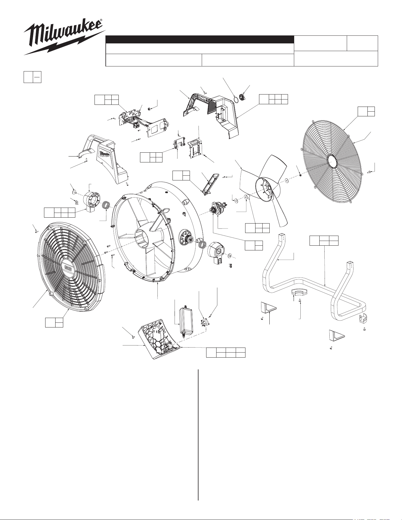
EXAMPLE:
Component Parts (Small #) Are Included
When Ordering The Assembly (Large #).
0
00
FIG. PART NO. DESCRIPTION OF PART NO. REQ.
1 --------------- Fan Dial (1)
2 --------------- Rear PCBA Housing (1)
3 --------------- Battery Engagement Interference (1)
4 --------------- Battery Terminal Cap (1)
5a --------------- M10 Nut (1)
5c --------------- PCBA (1)
6 --------------- Front PCBA Housing (1)
7 05-74-0047 M3 x 12mm (23)
8 --------------- Rear Grille (1)
9 --------------- M5 15mm Flange Button Head Screw (6)
10 --------------- M6 Nylock Nut (1)
11 --------------- M6 Washer (2)
12 --------------- 18" Fan Blade (1)
13 --------------- Fan Blade Adapter (1)
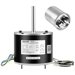
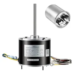
14 --------------- Motor (1)
15 --------------- Wire Trap Cap (1)
16 --------------- Fan Shroud (1)
17 --------------- Pivot Shoulder (2)
18 --------------- M6 x16mm Flange Head Screw (2)
19 --------------- M4 Flange Head Screw (8)
20 34-40-0511 O-Ring (8)
21 05-88-0203 M4 x 16mm Screw (18)
22 --------------- Front Grille (1)
23 --------------- M5 x 0.8 Screw (3)
FIG. PART NO. DESCRIPTION OF PART NO. REQ.
24a --------------- AC Housing (1)
24b --------------- AC Adapter (1)
24c --------------- M3 x 12mm Screw (4)
24d --------------- AC Plug (1)
25a --------------- Metal Leg (1)
25b --------------- Rear Rubber Foot (2)
25c --------------- Front Rubber Foot (2)
26 --------------- O-Ring (1)
30 31-44-0576 PCBA Housing Kit (1)
31 31-06-0040 Battery Interferance Kit (1)
32 31-15-0196 Shroud Kit (1)
33 22-08-0012 Fan Blade Kit (1)
34 23-38-0031 Motor Assembly (1)
35 31-50-0322 Fan Base Assembly (1)
36 14-20-0647 PCBA Assembly (1)
37 31-12-0073 AC Box Assembly (1)
38 43-52-0014 Front Grille Kit (1)
39 43-52-0015 Rear Griller Kit (1)
40 22-32-0017 Wire Trap Cap Kit (1)
41 12-20-0469 Service Nameplate (Not Shown) (1)
BULLETIN NO.
54-49-0890
SERVICE PARTS LIST
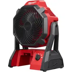
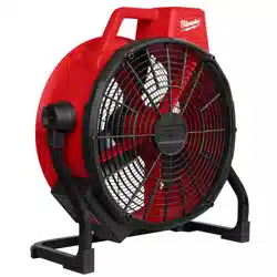
CATALOG NO. 0821-20
REVISED BULLETIN
SPECIFY CATALOG NO. AND SERIAL NO. WHEN ORDERING PARTS
M18
™
Brushless 18" Fan
SERIAL NO.
DATE
Nov. 2024
WIRING INSTRUCTION
P03A
See Pages 2-3
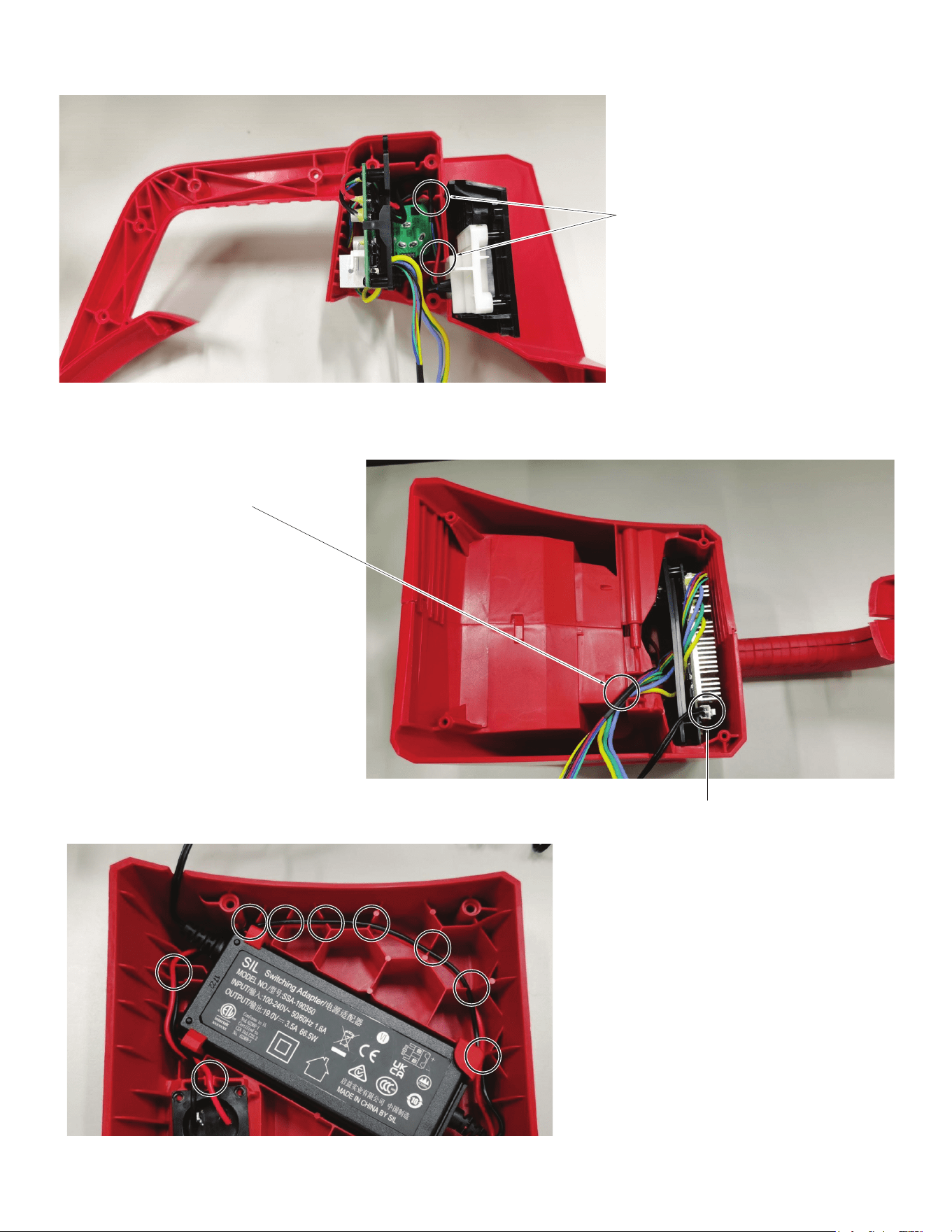
Confirm wires are placed in channels
and/or traps prior to assembly of the
PCBA housing.
Confirm wires are placed in channels and/or
traps prior to assembly of the AC housing.
Confirm wires are tucked behind the housing
before installation.
Ensure wire harness is connected.
Wiring
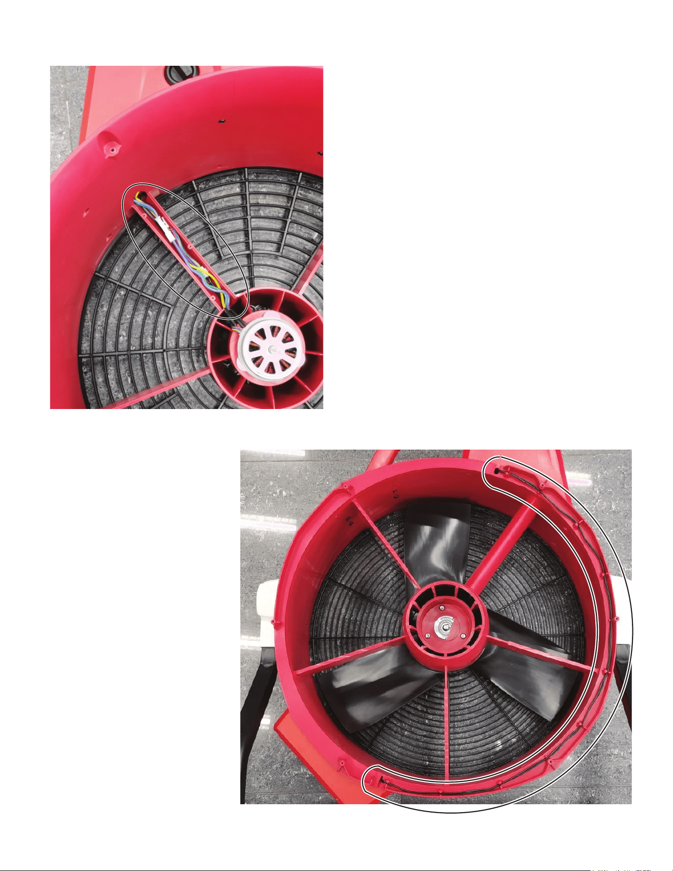
Prior to installation of the Wire Trap Cap (15),
Confirm wires are placed inside the fan shroud
channel.
Prior to installation of the Front Grille (22),
Confirm wires are placed inside the fan
shroud channel.
Wiring