
- 1 -
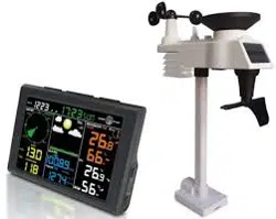
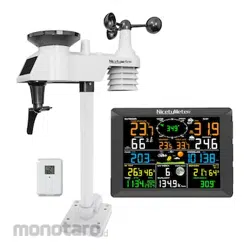
FT0320 Professional WiFi Weather Station
User Manual
1. Introduction..........................................................................3
2. Warnings and Cautions........................................................3
3. Getting Started.....................................................................3
3.1 Parts List.........................................................................3
3.2 Recommend Tools.........................................................6
3.3 Sensor Assembly Set Up................................................6
3.3.1 Install Integrated Outdoor Sensor Battery...... ..........7
3.3.2 Install Thermo-hygrometer Sensor Battery............10
3.4 Display Console............................................................13
3.4.1 Layout of Display Console.....................................13
3.4.2 Setup the Display Console ....................................14
3.4.3 Connect Sensors with Display Console.................16
3.5 Sensor Operation Verification.......................................17
3.6 WiFi Setup Guide.........................................................18
4. Sensors Pre-Installation.....................................................18
4.1 Test the Sensors Before Installation.............................18
4.2 Site Survey Before Installation......................................18
4.3 Best Practices for Wireless Communication.................19
5. Final Installation of Sensors...............................................20
5.1 Integrated outdoor Sensor Installation..........................20
5.2 Thermo-hygrometer Sensor Installation.......................26
6. Low Battery Icon................................................................27
7. Display Console Operation................................................27
7.1 Quick Display Mode......................................................27
7.2 Set (Program) Mode....................................................28

- 2 -
7.3 Chanel Selection Mode................................................31
7.4 Sensors Search Mode..................................................32
7.5 Max/Min Viewing and Reset Mode...............................33
7.6 Snooze Mode...............................................................34
7.7 Backlight Mode.............................................................35
8. Alarm Mode........................................................................36
8.1 Alarm Triggered............................................................36
8.2 View High/Low Alarm Value.........................................36
8.3 Setting the Alarms........................................................37
8.4 Alarm and Key Beeper ON/OFF...................................39
9. Optional Calibration Mode............................................40
9.1 Calibration of Temperature Mode.................................41
9.2 Calibration of Humidity Mode........................................41
9.3 Calibration of Sensors Mode........................................42
10. Other Features of Display Console..................................47
10.1 Weather Forecasting..................................................47
10.2 Weather Icons............................................................47
10.3 Moon Phase...............................................................48
10.4 Feels Like and AT Temperature ...............................49
10.5 Pressure Threshold Setting........................................51
10.6 Restore Factory Default..............................................51
11. Maintenance....................................................................51
12. Trouble Shooting Guide...................................................53
13. Specification....................................................................56
- 3 -
1.Introduction
Thank you for your purchase of the FT0320 Professional WIFI
Wireless Weather Station. The following user guide provides
step by step instructions for installation, operation and
troubleshooting.
2.Warnings and Cautions
Warning: Any metal object may attract a lightning strike,
including your weather station mounting pole. Never install the
weather station in a storm.
Warning: Installing your weather station in a high location
may result in injury or death. Perform as much of the initial
check out and operation on the ground and inside a building or
home. Only install the weather station on a clear, dry day.
3.Getting Started
The FT0320 weather station consists of a display console, a
sensor array with Integrated Outdoor Sensors, one remote
thermo-hygrometer sensor and mounting hardware.
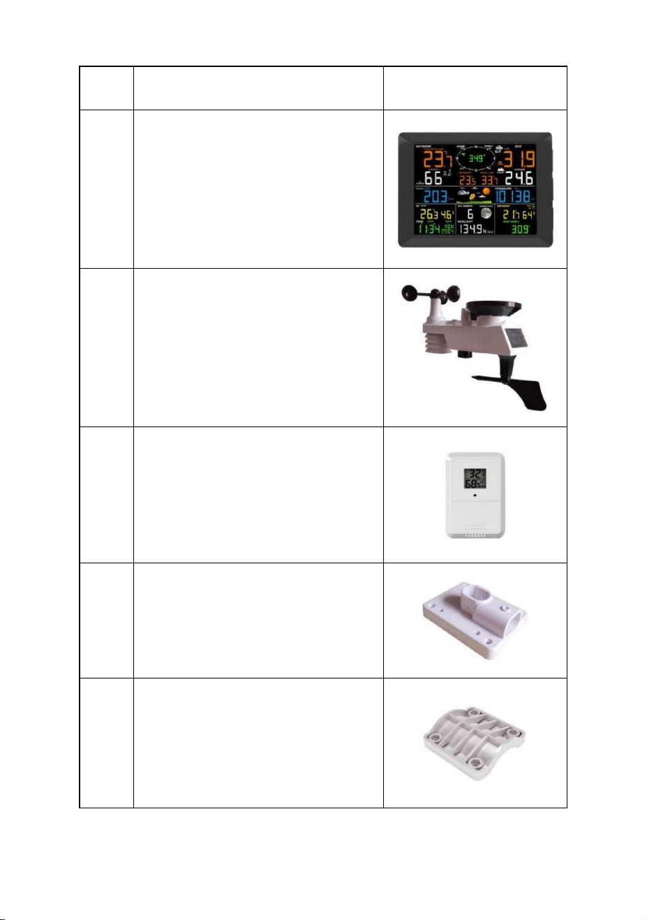
3.1 Parts List
The weather station consists of the following parts (as
referenced in Figure 1 ).
- 4 -
QTY
Item
Image
1
Display Console
Frame Dimensions :
8.47x6.22x0.87inch
(215x158x22mm)
LCD Dimensions:
6.7x4.9inch (170x125 mm)
1
Integrated Outdoor
Transmitter
Dimensions: 13x11x5.9 inch
(330x280x150mm)
1
Remote Thermo-hygrometer
Transmitter
Dimensions: 2.95x2.1x0.87inch
(75x53x22mm)
1
Foot Mounting (with pole
insert)
Dimensions: 4x3x1.5inch
(101x76x37mm)
1
Mounting Bracket Back Plate
(pole mount) Dimensions:
3x2.96x0.79inch
(76x75x20mm)

- 5 -
QTY
Item
Image
1
Mounting Pole Dimensions:
11.8x1.18x0.79inch
(300x30x20mm)
2
Pole mounting nuts (M3) / bolts
Ø3)
4
Pole mounting nuts (M5) / bolts
( Ø5)
4
Tapping screws
1
Manual
- 6 -
QTY
Item
Image
1
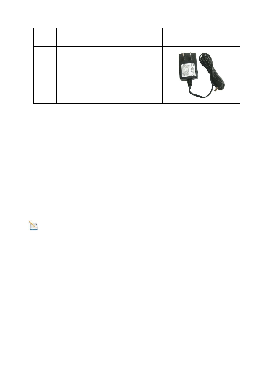
Power Adapter
Figure 1
3.2 Recommend Tools
● Precision screwdriver (for small Phillips screws)
● Compass or GPS (for wind direction calibration)
● Adjustable Wrench
● Hammer and nail for hanging remote Thermo-hygrometer
transmitter.
3.3 Sensor Assembly Set Up
Note: The outdoor sensor array must be powered and
updating before powering up the console, or the console will
stop scanning and connecting with the sensors.
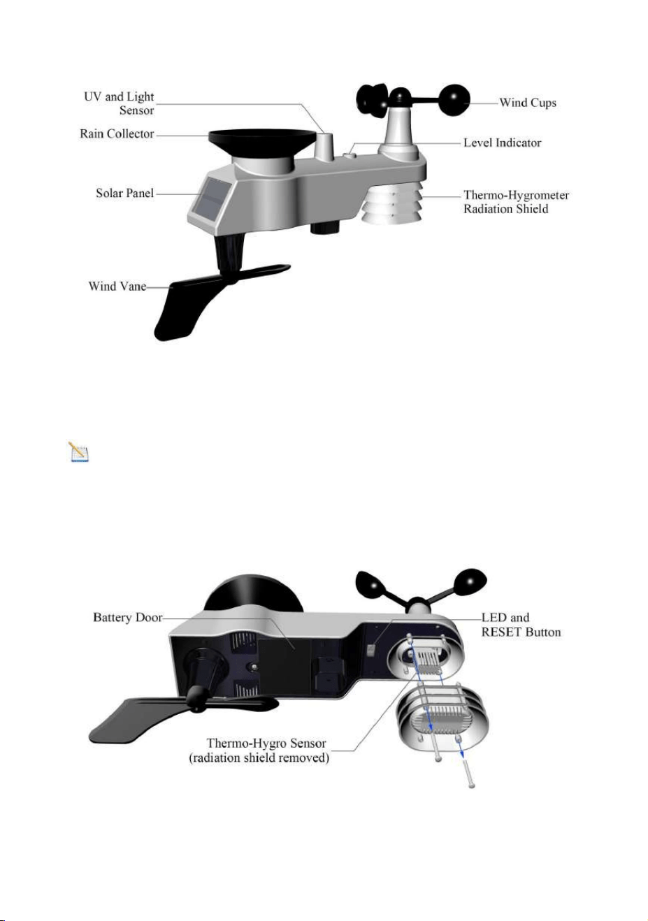
The following illustration shows the full segment of integrated
outdoor sensor including Thermo-Hygrometer, Wind, Rain, UV
and Sunlight sensor, as shown in Figure 2.
- 7 -
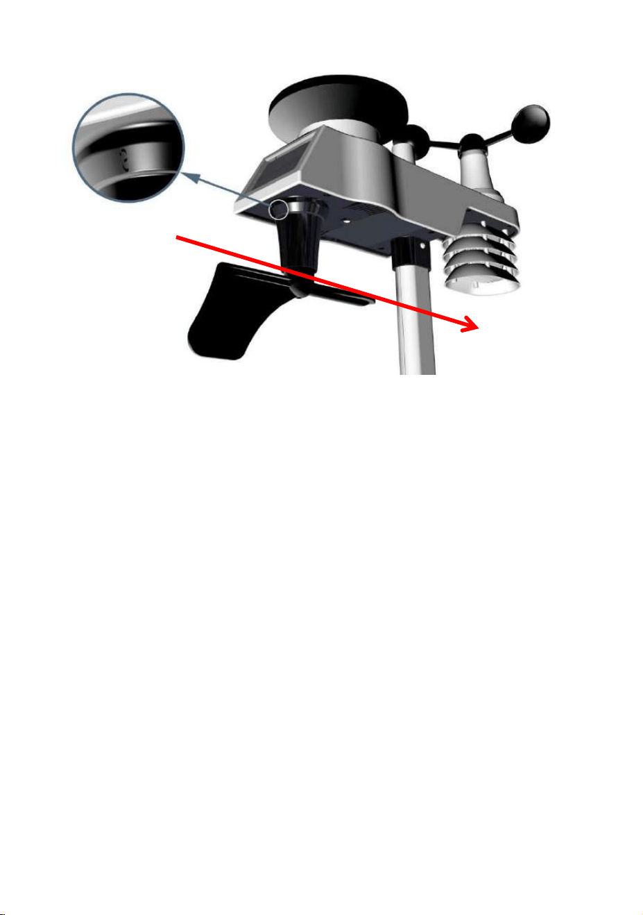
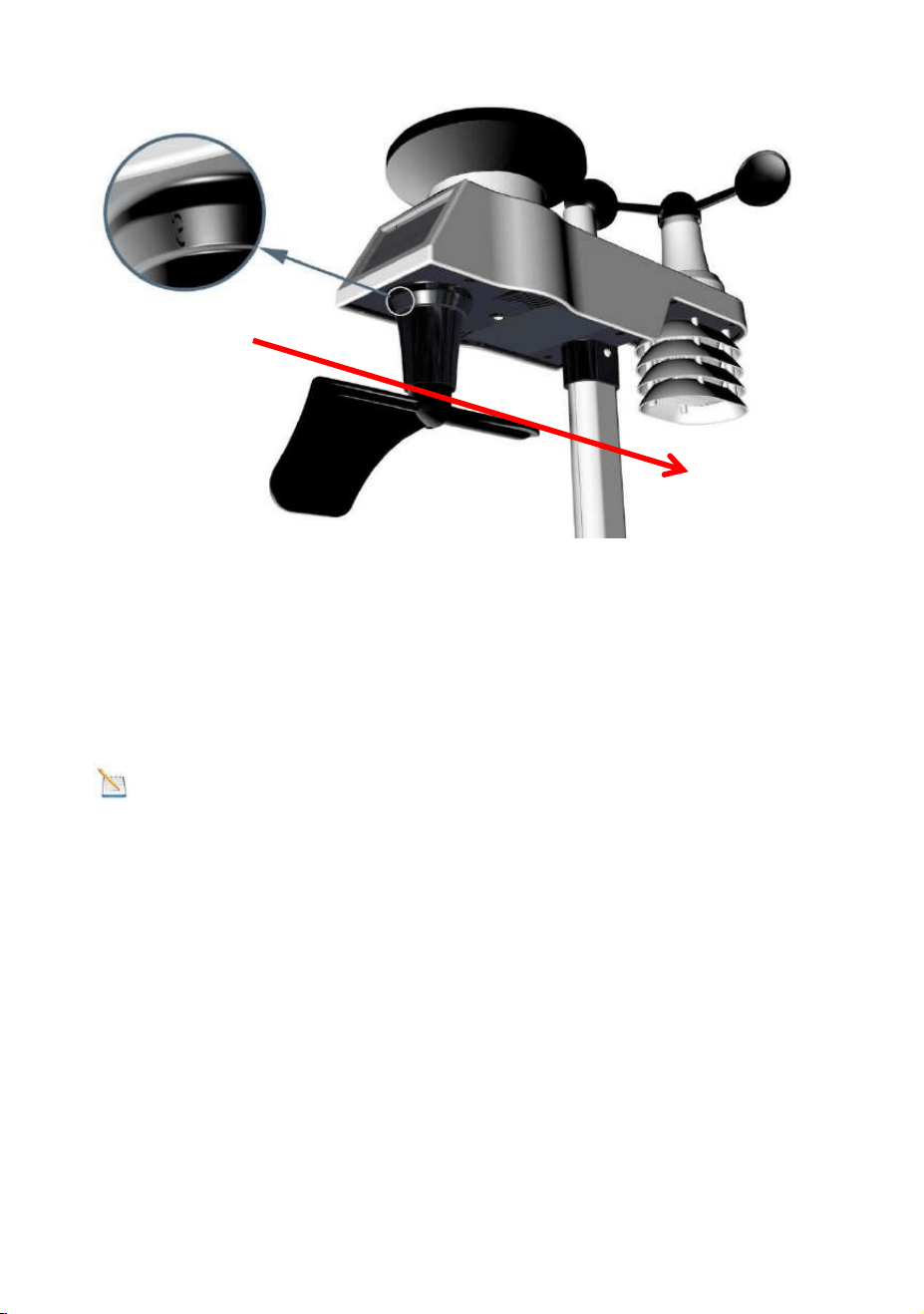
3.3.1 Install Integrated Outdoor Sensor Batter.
Locate the battery door on the bottom of transmitter as show in
Figure 3.
Note: Do not install the batteries backwards. You can
permanently damage the outdoor sensors. The solar panel
does not charge the batteries, so rechargeable batteries are
not recommended.
Figure 3
Figure 2
- 8 -
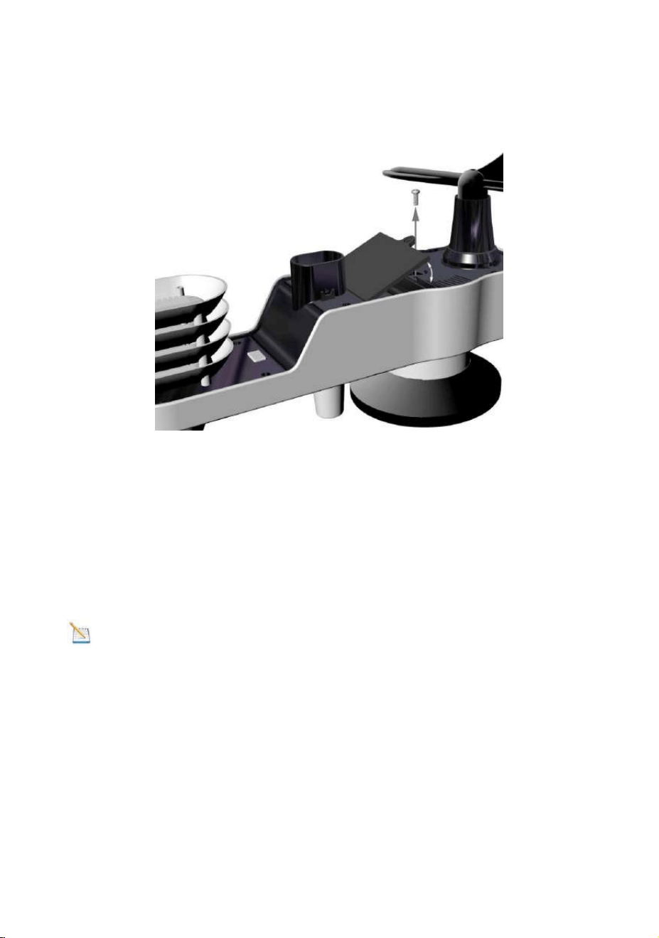
Remove the battery door on the back of the sensor by
removing the set screw, as show in Figure 4.
Figure 4
Inserting 3 AA fresh batteries as show in Figure 5. Close the
battery door. Make sure that the gasket (around the battery
compartment) is properly seated in its trace prior to closing the
door and Tighten the set screw.
Note: We recommend installing Lithium AA batteries for
outdoor sensors in cold weather environments
The Integrated outdoor sensor LED indicator(White button) will
light for 3 seconds, and then flash once per 16 seconds
thereafter. Each time it flashes, the sensor is transmitting data.
- 9 -
Figure 5
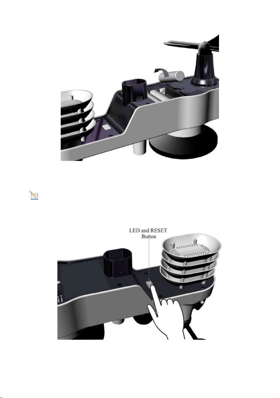
Note: If the sensor does not power up after inserting the
batteries, press the reset button as shown in Figure 6.
Figure 6
- 10 -
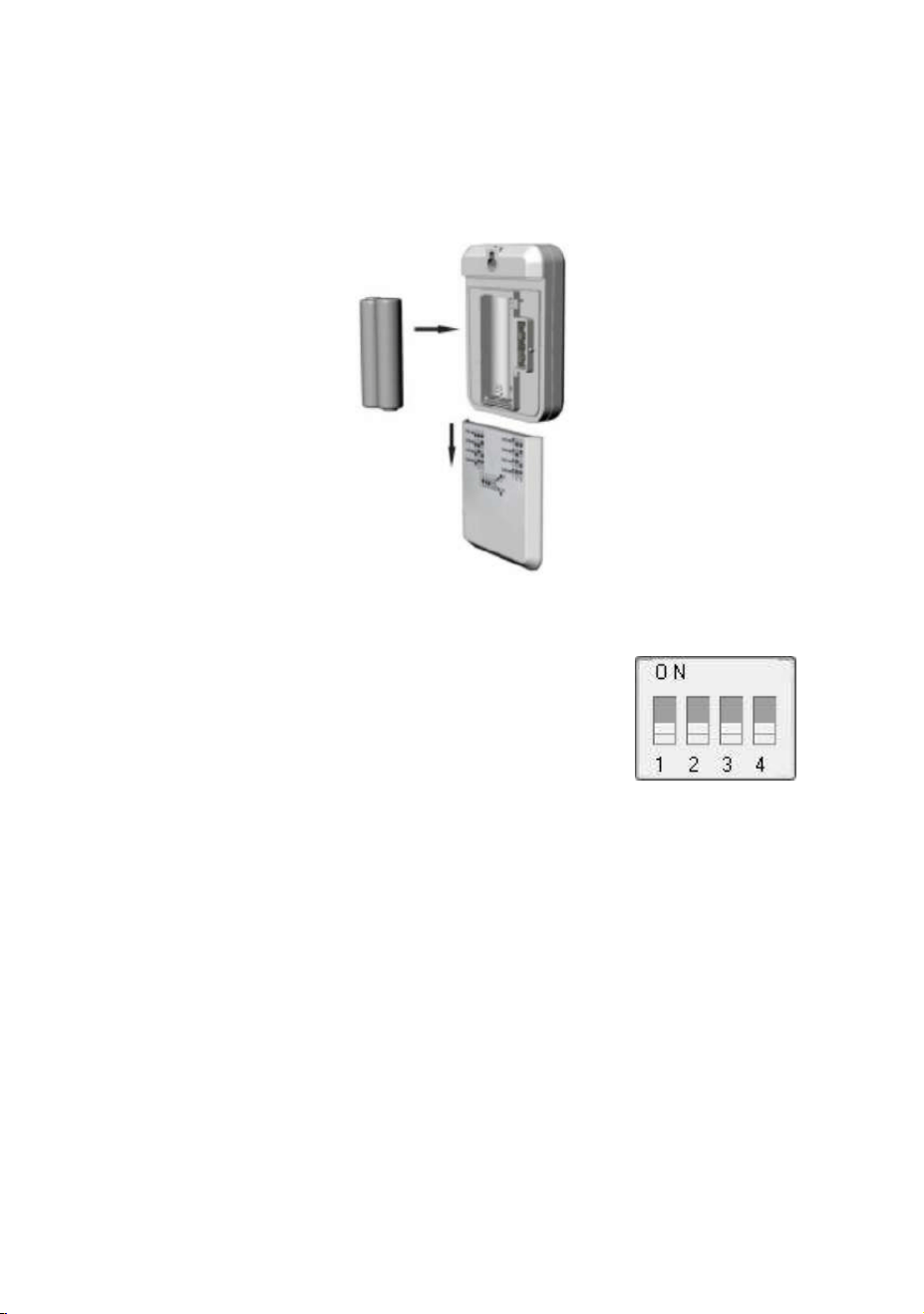
3.3.2 Install Thermo-hygrometer Sensor Battery.
Remove the battery door on the back of the sensor, as shown
in Figure 7.
Figure 7
1. BEFORE inserting the batteries, locate
the dip switches on the inside cover of
the lid of the transmitter.
The Figure 8 displays all four switches in
The OFF position (factory default setting).
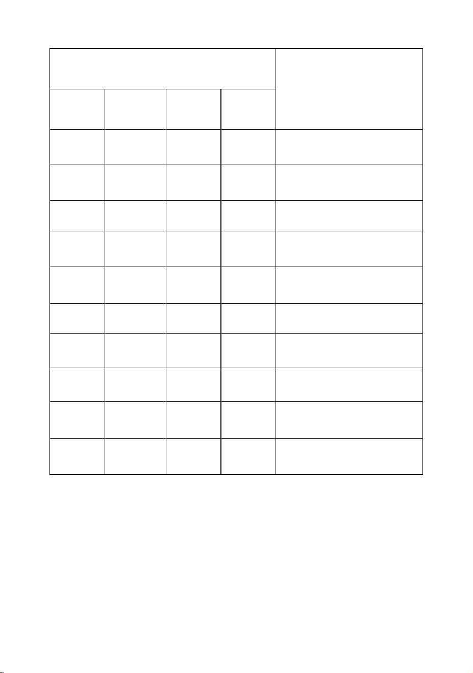
2. Channel Number: The weather station supports up to eight
transmitters. To set each channel number (the default is
Channel 1), change Dip Switches 1, 2 and 3, as referenced in
Table 1.
3. Temperature Units of Measure: To change the transmitter
display units of measure (°F vs. °C), change Dip Switch 4 as
referenced in Table 1.
Figure 8
- 11 -
DIP SWITCH
FUNCTION
1
2
3
4
DOWN
DOWN
DOWN
---
Channel 1
DOWN
DOWN
UP
---
Channel 2
DOWN
UP
DOWN
---
Channel 3
DOWN
UP
UP
---
Channel 4
UP
DOWN
DOWN
---
Channel 5
UP
DOWN
UP
---
Channel 6
UP
UP
DOWN
---
Channel 7
UP
UP
UP
---
Channel 8
---
---
---
DOWN
°F
---
---
---
UP
°C
Table 1
4. Insert two AAA batteries. (with the negative terminal of the
battery in contact with each spring). Lithium batteries are
recommended for cold weather environments., as shown in
Figure 7.
- 12 -
5. After inserting the new batteries, the remote sensor LED
indicator will light for 4 seconds, and then flash once per 60
seconds thereafter. Each time it flashes, the remote sensor is
transmitting data.
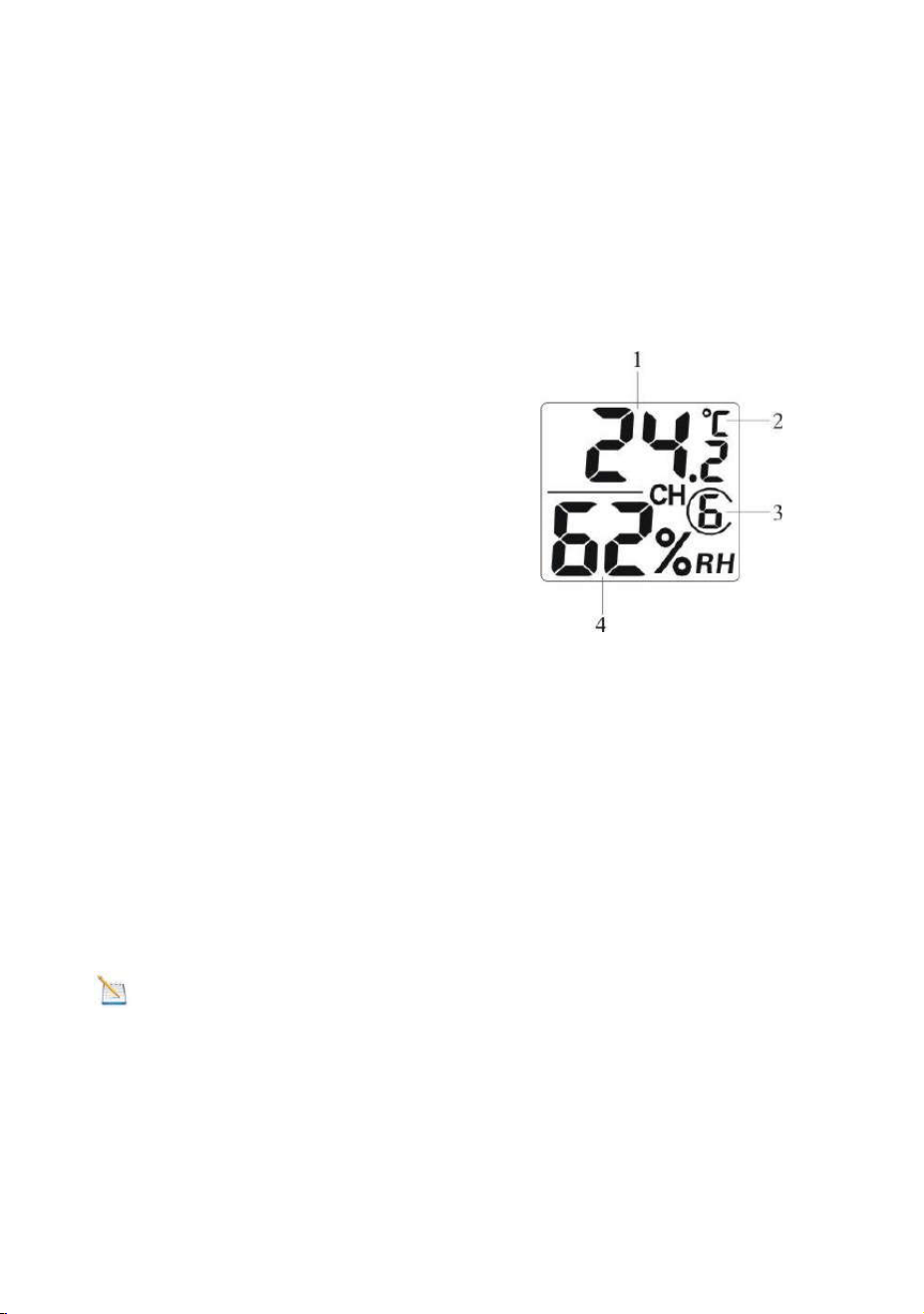
6. Verify the correct channel number (CH) and temperature
units of measure (°F vs. °C) are on the display, as shown in
Figure 9.
Figure 9
7. Close the battery door and and Make sure the door is closed
properly.
8. Each time you change the temperature unit and the channel,
You have to take out of batteries firstly before switching C/F
button and Channel, otherwise when batteries installed the
switch of C/F button will not be effective.
Note: We recommend fresh lithium batteries for sensors.
When outdoor temperature is lower than -4°F (-20°C), the
battery might not work properly.
(1) temperature
(2) temperature units
(°F vs. °C)
(3) channel number
(4) relative humidity
- 13 -
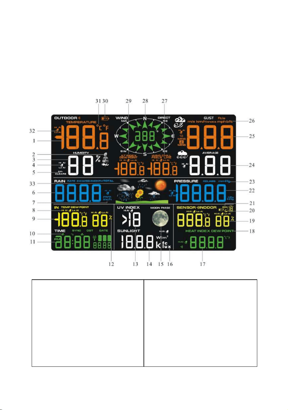
3.4 Display Console
3.4.1 Layout of Display Console
The following illustration shows the full segment LCD display
for feature description purposes only in Figure 10, and will not
appear like this during normal operation.
Figure 10
1. Outdoor temperature
display
2. WiFi network
3. Outdoor humidity display
4. Outdoor humidity HI/LO
alarm icon
5. Min/Max reset for 24h
icon
19. Outdoor temperature
and humidity display
20. Scroll mode indicator
21. Channel 1-8 indicator
22. Pressure (REL and ABS)
display
23. Pressure units of
measure

- 14 -
6. Rainfall display(RATE,
24h, WEEK,MONTH,
TOTAL)
7. Rainfall units of measure
8. Indoor temperature and
humidity HI/LO alarm icon
9. Indoor temperature and
humidity display
10. Time alarm icon
11. Time and date
12. Humidity units of
measure (%)
13. UV Index display
14. Sunshine intensity
15. Moon phase
16. Sunlight units of
measure
17. Sensor Heat index
display
18. Sensor Heat index(heat
index; dew point)
24. Wind speed average
display
25.Wind gust display
26.Wind speed units of
measure
27.Wind chill and feels like
HI/Lo alarm icon
28. Wind direction
29. OUT dew point and
AT(Apparent Temperature)
display icon
30. Integrated outdoor
transmitter Low power
indicator
31.Temperature units (°F
or °C)
32.Outdoor temperature
HI/LO alarm icon
33.Weather forecast
3.4.2 Setup the Display Console
1. Plug in the display console with power adapter.
BL ON will display in the time area for three seconds when
powered up.
Note: It is recommended to plug in the power adapter to
reduce the battery consumption and extend the service life
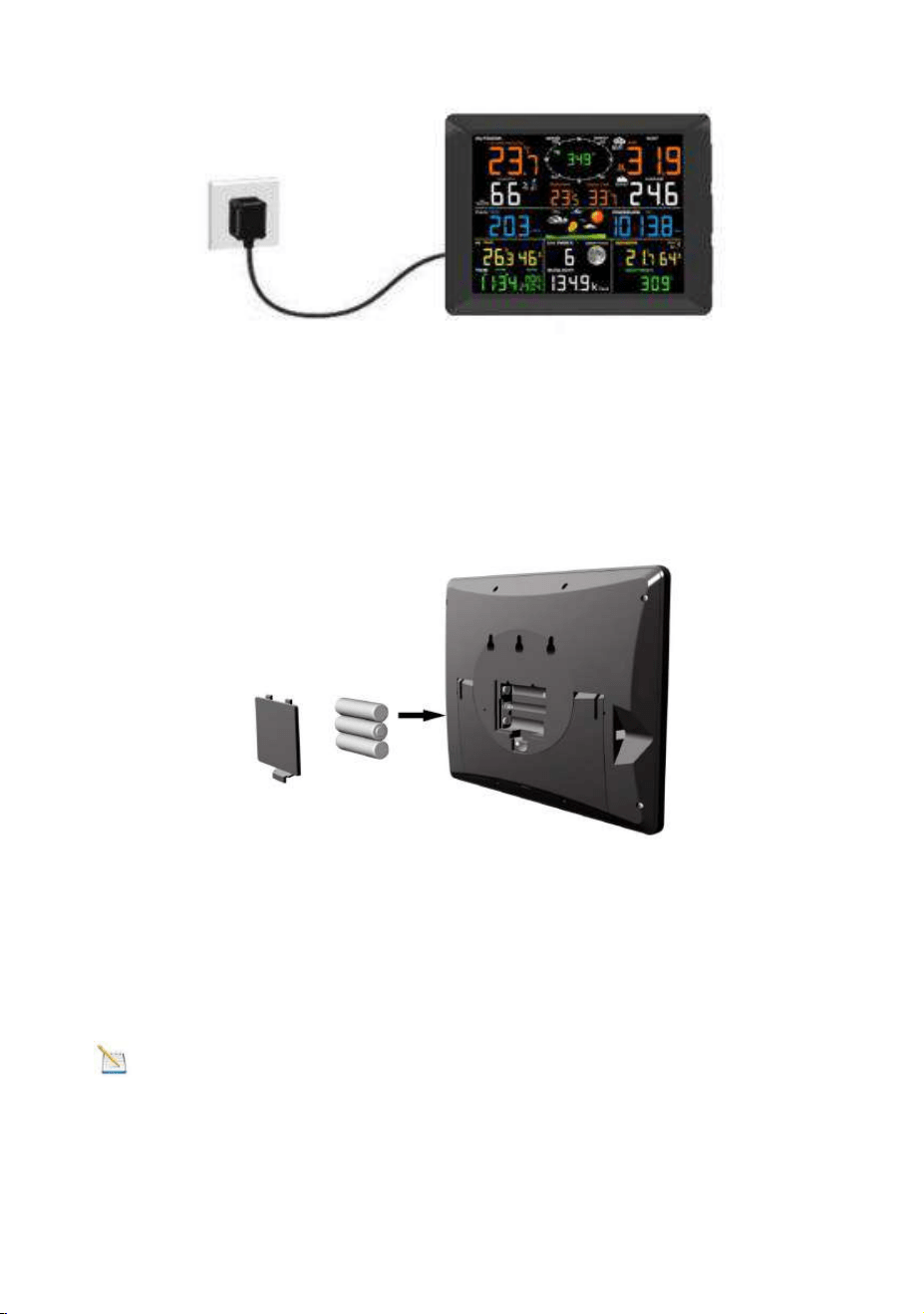
- 15 -
2. Display Console Batteries Installation
Remove the battery door on the back of the display, as shown
in Figure 11. Install three AAA (alkaline or lithium)) batteries.
The display will beep once and layout of display will light up for
a few seconds to verify all segments are operating properly.
Figure 11
Replace the battery door, and unfold out the desk stand to
place the console in the upright position
Note: The battery is a back-up of weather station console,
saving console settings when powered off from adaptor

- 16 -
.
3.4.3 Connect Sensors with Display Console
Once the display console is powered up, it will automatically
scan all the nearby Integrated Outdoor sensors and the
Thermo-hygrometer Sensors.
Note: Do not press any button until all the remote sensors
report in the display screen, otherwise the display console will
terminate to connect with remote sensors.
Note: While in the search mode, the remote search icon
will be constantly displayed until all the measured values
received. The console will automatically switch to the normal
mode from which all further settings can be performed.
When connected with the Integrated Outdoor Sensor, the
measured value (Outdoor temperature, humidity, wind speed,
wind direction, wind gust and average, rainfall, UV and
Sunlight index, Dew point and feels like) will show up on the
display console.
When connected with the Thermo-hygrometer Sensor, the
measured value (Sensor temperature, humidity, heat index
and dew point) will show up on right bottom of the display
console.
If you have more than one thermo-hygrometer sensors, the
display will automatically toggle between sensors until all
sensors have reported in.

- 17 -
Note: Make sure that the distance between weather station
sensors and display console should be within 10ft (3m) to 100ft
(30m). If the weather station sensors is too close or too far
away, it may not receive a proper signal. If you have more than
one Thermo-hygrometer sensor, make sure that they are all
powered up and transmitting on different channels.
3.5 Sensor Operation Verification
The following steps verify proper operation of the sensors prior
to install the sensor array.
1. Verify proper operation of the rain gauge. Tip the
Integrated outdoor sensor back and forth several times. You
will heard a “ticking” sound within the rain gauge. Verify the
rain reading on the display console is not reading 0.00. Each
“ticking” represents 0.01 inch of rainfall.
2. Verify proper operating of the wind speed. Rotate the
wind cups manually or with a constant speed fan. Verify the
wind speed is not reading 0.0.
3. Verify proper operation of in/outdoor temperature.
Verify the indoor and outdoor temperature match closely with
the console and sensor array in the same location (about 5 to
10’ (1.5 to 3 meters) apart). The sensors should be within 4°F
/2°C (the accuracy is ± 2°F/1°C). Allow about 30 minutes for
both sensors to stabilize.
4. Verify proper operation of in/outdoor humidity. Verify
the indoor and outdoor humidity. Verify the indoor and outdoor
humidity match closely with the console and sensor array in
the same location (about 5 to 10’ (1.5 to 3 meters) apart). The

- 18 -
sensors should be within 10% (the accuracy is ± 5%). Allow
about 30 minutes for both sensors to stabilize.
3.6 WiFi Connection Guide
For weather station models with WiFi function, you can start to
set up wifi connection and weather data uploading. For details
of this part, please refer to the separate “WiFi Setup Guide”
Manual.
4. Sensors Pre-installation
4.1 Test the Sensors Before Installation
Recommend to operate and test the weather station for one
week before installing it in the permanent location. In this
period, you can check out all of the functions, ensure proper
operation, and familiarize with the professional weather station
and calibration procedures. This will also allow you to test the
wireless range of the weather station.
4.2 Site Survey Before Before Installation
Do a site survey before installing the weather station. Take the
following points into Consider:
1. You must clean the rain gauge once per year and change
the batteries every two years. Provide as easy access to the
weather station.
2. Avoid radiant heat transfer from buildings and structures.
In general, install the sensor array at least 5ft (1.5m) from any
building, structure, ground, or roof top.

- 19 -
3. Avoid wind and rain obstructions. The rule of thumb is to
install the sensor array at least four times the distance of the
height of the tallest obstruction. For example, if the building is
20ft (6m) tall, install 4 x (20 – 6)’ = 56ft (17m) away. Use
common sense. If the weather station is installed next to a tall
building, the wind and rain will not be accurate.
4. Wireless Range. The radio communication between
display console and transmitter in an open field can reach a
distance of up to 330ft (100m), assume there are no interfering
obstacles such as buildings, trees, vehicles, high voltage lines.
Wireless radio signals will not penetrate metal buildings. Most
wireless applications will only reach up to100ft (30m) due to
building obstructions, walls and interference.
5. Radio interference such as PCs, radios or TV sets can, in
the worst case, entirely cut off radio communication. Please
take this into consideration when choosing display console or
mounting locations.
4.3 Best Practices for Wireless Communication
Wireless communication is susceptible to other interference,
such as distance, walls and metal barriers. We recommend the
following best and useful practices for trouble-free wireless
communication.
1. Electro-Magnetic Interference (EMI). Keep the console
several feet away from computer monitors and TVs.
2. Radio Frequency Interference (RFI). If you have other
433 MHz devices and communication is intermittent, try turning
off these other devices for troubleshooting purposes. You may
need to relocate the wireless transmitters or receivers to avoid
intermittent communication.
- 20 -
3. Line of Sight Rating. This device is rated at 300ft line of
sight (no interference, barriers or walls) but typically you will
get 100ft maximum under most real-world installations, which
include passing through barriers or walls.
4. Metal Barriers. Radio frequency will not pass through
metal barriers such as aluminum siding. If you have metal
siding, align the remote and console through a window to get a
clear line of sight.
The following is a table of reception loss vs. the transmission
medium. Each “wall”or obstruction decreases the transmission
range by the factor shown below.
Medium
RF Signal Strength
Reduction
Glass (untreated)
5-15%
Plastics
10-15%
Wood
10-40%
Brick
10-40%
Concrete
40-80%
Metal
90-100%
5. Final Installation of Sensors
5.1 Integrated Outdoor Sensor Installation
- 21 -
This Professional Weather Station can be used in both the
Northern and Southern Hemispheres. Prior to installation, you
will need to calibrate the wind direction.
Note: There are four alphabet letter of N, E, S and W
around the wind direction.(N is North, E is East, S is South, W
is West)
Northern Hemispheres
Southern Hemispheres
5.1.1 Northern Hemispheres (NOR) References.
The cardinal directions (N, S, E, W) molded on the body of the
outdoor sensor are indicators for the Northern Hemisphere
only.
Step 1: There is a “S” indicator on the wind vane that indicates
South, as shown in Figure 12. Check the wind directions with
compass and Align this “S” marker in the direction of South.
- 22 -
Figure 12
Step 2: Console operation set to Northern Hemispheres( NOR
in the time area) in Location division. (Check the detailed step
of setting the time area in the part 17 of Chapter 7.2)
5.1.2 Southern Hemispheres (NOR) References.
For Southern Hemisphere installations, ignore the direction (N,
S, E, W), and face the solar panel to the North (and in a
sunny position) when it comes to install the Integrated outdoor
sensor, as show in figure 13.
Step 1: Install the Integrated outdoor transmitter and face the
solar panel to the North.
South
North
- 23 -
Figure 13
Step 2: Console operation set to Southern Hemispheres( SOU
in the time area) in Location division. (Check the detailed step
of setting the time area in the part 17 of Chapter 7.2)
Note: The location division (NOR or SOU) on the Display
Console and the directions of the sensor have to be adjusted
to match with your real location.
If the wind direction sensor is not positioned correctly during
installation, permanent wind direction error will be introduced.
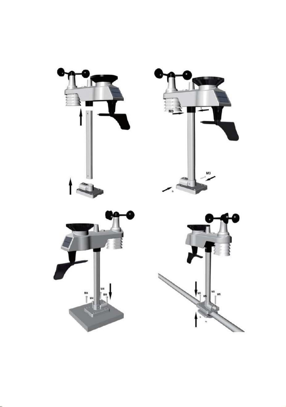
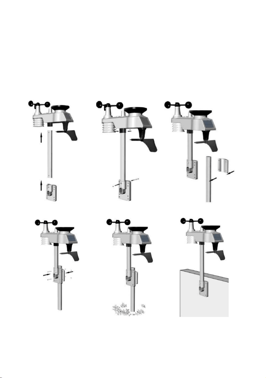
5.1.3 Mounting & Fixing the Sensor Horizontally
Fasten the integrated outdoor sensor to the mounting pole
brackets with two foot-mounting screws Ø3 bolts and M3 nuts.
South
North
- 24 -
Then, tighten the mounting pole to your existing mounting pole
with the four bolts ( Ø5) and nuts (M5) , or fix it on the flat
surface with four tapping screws, as show in Figure 14.
Figure 14
- 25 -
5.1.4 Mounting & Fixing the Sensor Vertically
Fasten the integrated outdoor sensor to the mounting pole
brackets with two foot-mounting screws Ø3 bolts and M3 nuts.
Then, tighten the mounting pole to your existing mounting pole
with the four bolts ( Ø5) and nuts (M5) , or fix it on the flat
surface with four tapping screws, as show in Figure 15.
Figure 15
- 26 -
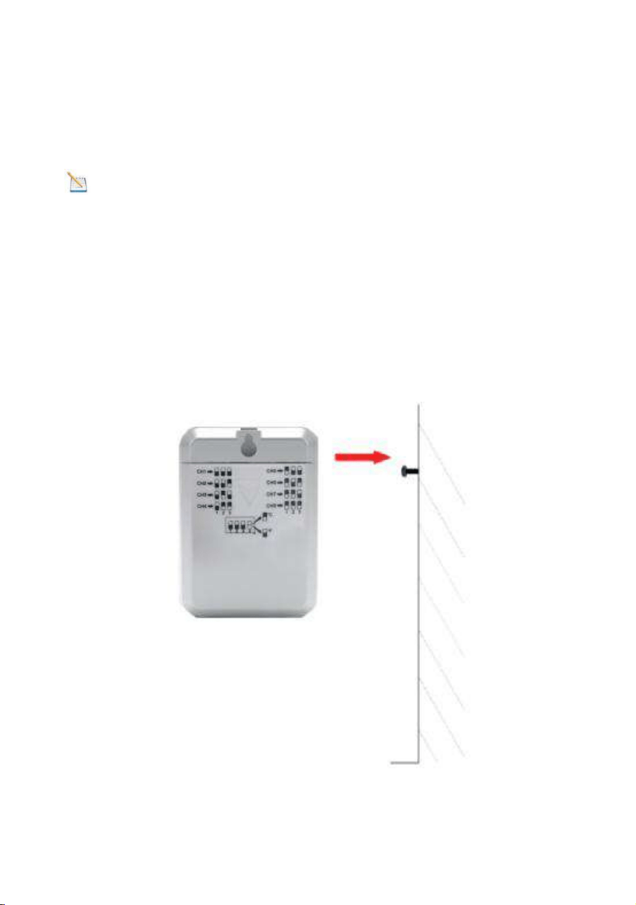
5.2 Thermo-hygrometer Sensor Installation
It is recommended you mount the Thermo-hygrometer sensor
outside in a shaded area.
Note: The North facing wall is preferred because it is in the
shade most of the day. The Direct sunlight and radiant heat
sources will result an inaccurate temperature readings.
The sensor is water resistant, it is best to mount in a well
protected area, such as under an eve. Use a screw or nail (not
included) to affix the remote sensor to the wall, the sensor can
also lay flat or on the table,as shown in Figure 16.
Figure 16

- 27 -
6. Low Battery Icon
A low battery indicator icon is shown in the display window for
thermo-hygrometer sensor/integrated outdoor sensor.
When the low battery icon appears (The thermo-hygrometer
battery voltage is lower than 2.4V. The Integrated outdoor
sensor battery voltage is lower than 3.6V), replace the
batteries in the sensor with fresh batteries.
Be sure to never mix old and new batteries, and never mix
battery types such as alkaline and lithium together.
7. Display Console Operation
7.1 Quick Display Mode
Note: The display console has five keys for easy operation:
MAX/MIN/- key, ALARM key, SET/MODE key, CHANNEL/+
and SNOOZE key.
Note: To exit the Quick Display Mode at any time, press the
SNOOZE key of the display console.
While in Normal Mode, press (do not hold) the SET/MODE key
to enter the Quick Display Mode as follows:
Once for time, time/week and date,
Twice for indoor temperature, dew point,
Three for rainfall.
Four for outdoor dew point temperature

- 28 -
Five for wind average
Six for pressure
Seven for sensor dew point
1.Time, Time/Week and Date. Press the CHANNEL/+ or
MAX/MIN/- key to toggle between time, time/week and date.
2. Indoor Temperature. Press the CHANNEL/+ or MAX/MIN/-
key to toggle between temperature and dew point
3. Rainfall. Press the CHANNEL/+ or MAX/MIN/- key to
toggle between rate, 24h, week, month and total.
To clear the total rain, press the CHANNEL/+ or MAX/MIN/-
button until total rain is displayed. The total rain will flash.
Press and hold the SET button for five seconds until total rain
reads 0.0.
4. Outdoor Dew Point. Press the CHANNEL/+ or MAX/MIN/-
key to toggle between AT(Apparent Temperature) and dew
point.
5. Wind Average. Press the CHANNEL/+ or MAX/MIN/- key
to toggle between current, 2mins and 10 minutes.
6. Absolute Pressure and Relative Pressure. Press the
CHANNEL/+ or MAX/MIN/- key to toggle between absolute
pressure and relative pressure.
7. Sensor Heat Index. Press the CHANNEL/+ or MAX/MIN/-
key to toggle between sensor heat index and dew point.
7.2 Set (Program) Mode
While in Normal Mode, press and hold the SET/MODE key
for at least three seconds to enter the Set Mode. The first
setting will begin flashing. You can press the SET/MODE key
again to skip any step, as defined below.

- 29 -
Note: In the Set mode, press the CHANNEL/+ key or
MAX/MIN/- key to change or scroll the setting value. Hold the
CHANNEL/+ key or MAX/MIN/- key for three seconds to
increase/decrease rapidly.
Note: To exit the Set mode at any time, press the SNOOZE
button of the display console.
1. Time SYNC(default: ON). Press the SET/MODE key again
to set the network time sync. Press the CHANNEL/+ key or
MAX/MIN/- key to switch between SYNC time ON/OFF of
measure. Synchronize the time of the device with WiFi.
2. 12/24 Hour Format (default: 24h). Press the SET/MODE
key again to adjust the 12/24 hour format setting (FMT). Press
the CHANNEL/+ key or MAX/MIN/- key to change between 12
hour and 24 hour format.
3. Change Hour. press the SET/MODE key again to set the
hour. Press the CHANNEL/+ key or MAX/MIN/- key to adjust
the hour up or down. During afternoon hours the PM icon will
display.
4. Change Minute. Press the SET/MODE key again to set the
minute. Press the CHANNEL/+ key or MAX/MIN/- key key to
adjust the minute up or down.
5. Date Format (default: MM-DD). Press the SET/MODE key
again to enter the Day/Month format mode. Press the
CHANNEL/+ or MAX/MIN/- key to switch between MM-DD-YY,
DD-MM-YY.

- 30 -
6. Change Month. Press the SET/MODE key again to set the
calendar month. Press the CHANNEL/+ key or MAX/MIN/- key
to adjust the calendar month.
7. Change Day. Press the SET/MODE key again to set the
calendar day. Press the CHANNEL/+ key or MAX/MIN/- key
to adjust the calendar day.
8. Change Year. Press the SET/MODE key again to set the
calendar year. Press the CHANNEL/+ key or MAX/MIN/- key to
adjust the calendar year.
9. Max/Min Clearing (default: ON). Press the SET/MODE
key again to set the Max/Min clearing mode (CLR). The
Max/Min can be programmed to clear daily (at midnight) or
manually. Press the CHANNEL/+ key or MAX/MIN/- key to
switch between ON (Clears 24h) and OFF (Manually).
10. Temperature Units of Measure (default: °F):. Press the
SET/MODE key again to change the temperature units of
measure. Press the CHANNEL/+ key or MAX/MIN/- key to
switch between °F and °C units of measure.
11. Wind Speed Units of Measure (default: Mph). Press the
SET/MODE key again to change the wind speed units of
measure . Press the CHANNEL/+ key or MAX/MIN/- key to
toggle the wind speed units between m/s, km/h, mph, knots, bft
or ft/s.
12. Rainfall Units of Measure (default: Inch). Press the
SET/MODE key again to change the Rainfall units of measure.
Press CHANNEL/+ key or MAX/MIN/- key to toggle the rainfall
units between mm and inch.
13. Barometric Pressure Display Units(default: InHg).
Press the SET/MODE key again to change the pressure units

- 31 -
of measure. Press the CHANNEL/+ key or MAX/MIN/- key to
toggle the pressure units between mmhg, inHg or hPa.
14. Pressure Threshold Setting (default level 2). Press the
SET/MODE key again to change the pressure threshold. Press
the CHANNEL/+ key or MAX/MIN/- key to change pressure
threshold 2 hPa to 4 hPa. (For detailed information of this part
please refer to 10.5)
15. Weather Icons Setting (default: partly cloudy). Press
the SET/MODE key again to change the initial weather icon.
Press the CHANNEL/+ key or MAX/MIN/- key to select the
initial weather icon of Sunny, Cloudy, Partly Cloudy or Rainy.
(For detailed information of this part please refer to 10.2)
16. Sunlight Display Units (default: lux). Press the SET/
MODE key again to change the sunlight units of measure.
Press the CHANNEL/+ key or MAX/MIN/- key to toggle the
sunlight units between , W/
㎡
, fc or lux.
17. Location Division. (default: Northern Hemisphere).
Press the SET/MODE key again to change the location
division. Press the CHANNEL/+ key or MAX/MIN/- key to
toggle the position of the earth Northern Hemisphere (NOR) or
Southern Hemisphere (SOU). (Refer to 5.0 Final Installation
of Sensors)
7.3 Channel Selection Mode
Press the CHANNEL/+ button to switch the sensor display
between remote thermo-hygrometer sensors 1 through 8, and
scroll mode . In scroll mode, all of the detected thermo-
hygrometer sensors will be displayed in five second intervals.

- 32 -
Note: Only when have more than one thermo-hygrometer
sensor connected with the display console could activate this
features.
7.4 Sensors Search Mode
If a sensor loses communication, dashes (--.-) will be displayed.
If a specific channel is lost, press the CHANNEL/+ button to
display that channel prior to entering the search mode.
To reacquire the lost signal, press and hold the CHANNEL/+
button for 3 seconds to enter the sensor search mode.
The icon AIO will appear in the time area.You can synchronize
one or all of individual sensors. press the CHANNEL/+ key or
MAX/MIN/- key to toggle between the following sensors:
AIO. Synchronizes Integrated outdoor transmitter
CH*. Synchronizes Channel 1-8 Sensors (dependent on
which channel is displayed before entering the Sensor
Search Mode).
ALL. Synchronizes All Sensors.
NOT. Do nothing and exit the Sensor Search Mode.
After selecting one of the above options, press the SET/MODE
key to re-sync, and the display will return to normal mode. Do
not press any buttons until the synchronization is complete.
The remote search icon will display constantly for 3
minutes until the signal is reacquired.

- 33 -
7.5 Max/Min Viewing and Reset Mode
7.5.1 Max Record Viewing and Reset
Note: If you own more than one thermo-hygrometer sensor,
the minimum and maximum value of all sensors will be cleared
in the reset mode.
In normal mode, press (do not hold) the MAX/MIN/- key, the
MAX icon will be displayed in date area.
Press the SET/MODE key to view Max values of rainfall (rate,
24h, week or month), wind (Gust and Average), pressure (ABS
or REL), UV and Sunlight, outdoor temp and humidity (AT and
feels like), indoor temp and humidity (temperature or dew point)
and sensor temperature and humidity, sensor dew point (heat
index).
Press the CHANNEL/+ button to switch the display between
remote thermo-hygrometer sensors 1 through 8 to view Max
values.
Press the MAX/MIN/- key for three seconds to clear all Max
values.(Rainfall, wind speed, wind gust, pressure, temperature
and humidity maximum values).
Press the SNOOZE key to exit the min/max checking and reset
mode, return to normal display mode.
Note: The Maximum values will display the current values
after reset.

- 34 -
7.5.2 Min Record Viewing and Reset
Press the MAX/MIN/- key again (do not hold), the MIN icon will
be displayed. Press the SET/MODE key to view Min values of
pressure (ABS or REL), outdoor temperature and humidity((AT
and feels like), indoor temperature and humidity(temperature
or dew point), sensor temperature and humidity, sensor dew
point(heat index).
Press the CHANNEL/+ button to switch the display between
remote thermo-hygrometer sensors 1 through 8 to view Min
values.
Press the MAX/MIN/- key for three seconds to clear all Min
values.(pressure, temperature and humidity minimum values).
Press the SNOOZE key to exit the min/max checking and reset
mode, return to normal display mode.
Note: The Minimum values will display the current values
after reset.
7.6 Snooze Mode
If the alarm sounds, and you wish to silence the alarm, press
the SNOOZE key, the backlight will turn on. The alarm icon will
continue to flash and the alarm will silence for five minute.
Press any key (MIN/MAX,SET/MODE,ALARM,CHANNEL) to
permanently exit the Snooze mode.

- 35 -
7.7 Backlight Mode
7.7.1 Adjustable Brightness of Backlight
There are 3 levels of brightness of display backlight. When the
backlight is on, press SNOOZE key to switch between the 3
levels.
When backlight is off, press and hold the SNOOZE key for
three seconds, the backlight will turn on permanently, and BL
ON icon will be displayed for three seconds in the date area.
To turn off the display backlight at any time, press and hold the
SNOOZE key for two seconds. BL OFF icon will be displayed
for three seconds in the date area.
Note: If the display console plugged into AC adapter power,
the time area will display AC ON and the backlight will remain
on. It is not recommended leaving the display backlight on for
a long period of time when operating on batteries only, or the
batteries will run out quickly.
Note: The backlight operation is different when operating
on batteries to save power.
If the display console only powered by batter, and backlight is
off, Press the SNOOZE/LIGHT button once. The backlight will
turn on for five seconds, and if no operation is performed for
three seconds, the backlight will turn off.

- 36 -
8. Alarm Mode
The weather station includes the following alarms:
8.1 Alarm Triggered
When an alarm condition is exceed, the alarm icon will flash
(visual) and the alarm beeper will sound (audible). To
silence the beeper, press any key.
8.2 View High/Low Alarms Value
To view the current alarm settings, press the ALARM key to
enter the alarm mode. HI AL 1 will be displayed in the date
area. At the same time Alarm 1 time and HI alarm parameters
of indoor temperature and humidity, outdoor temperature and
humidity, rain rate, AT, feels like, wind gust, wind average,
Time (Alarm 1 and Alarm 2)
Outdoor Temperature
Outdoor Humidity
Outdoor AT(Apparent
Temperature)
Outdoor Dew Point
Outdoor Feels Like
Temperature
Outdoor Dew Point
Wind Gust
Wind Average
Rate Rainfall
24 Hour Rainfall
Absolute Pressure
Relative Pressure
Indoor Temperature
Indoor Humidity
Indoor Dew Point
UV Index
Sunlight
Sensor(CH1)
Temperature
Sensor(CH1) Humidity
Sensor(CH1) Heat
Index
Sensor(CH1) Dew Point

- 37 -
absolute pressure, UV index, Sunlight, Sensor(CH1) temp
humidity and dew point are displayed.
Press SET/MODE key to view Alarm 2 time and HI alarm
parameters of indoor dew point, 24h rainfall, outdoor dew point,
relative pressure and Sensor(CH1) heat index.
Press ALARM key again to view the LOW alarms along with
the alarm clock time in the same way as HI alarms.
Press ALARM key again to return to normal mode.
Note: Press the SNOOZE key at any time to return to the
normal mode in HI/Low alarm mode.
8.3 Setting the Alarms
Press ALARM key to enter the alarm mode.
Press and hold the SET/MODE key for three seconds. The first
alarm parameter will begin flashing (alarm hour).
To save the alarm setting and proceed to the next alarm
parameter, Press (do not hold) the SET/MODE key.
To adjust the alarm parameter, press the CHANNEL/+ key or
MAX/MIN/- key to increase or decrease the alarm settings, or
press and hold the CHANNEL/+ key or MAX/MIN/- key for
three seconds to increase or decrease the alarm settings
rapidly.

- 38 -
Press the ALARM key to turn on (the alarm icon will appear )
and off the alarm.
Press the SNOOZE key once at any time to return to the
normal mode. After 30 seconds of inactivity, the alarm mode
will time out and return to normal mode.
The following is a list of the individual alarm parameters that
are set (in order):
1.Alarm hour(alarm 1)
2.Alarm minute(alarm 1)
3.Alarm hour(alarm 2)
4.Alarm minute(alarm 2)
5.Outdoor temp HI alarm
6.Outdoor temp low alarm
7.Outdoor humidity HI alarm
8.Outdoor humidity low alarm
9.Outdoor AT high alarm
10.Outdoor AT low alarm
11.Outdoor dew point HI alarm
12.Outdoor dew point low alarm
13.Outdoor feels like HI alarm
14.Outdoor feels like low alarm
15.Wind Gust HI alarm
16.Wind Average HI alarm
17.Rainfall (RATE) HI alarm
18.Rainfall (24h) HI alarm
19.Absolute pressure HI alarm
20.Absolute pressure low alarm
21.Relative pressure HI alarm
22.Relative pressure low alarm
23.Indoor temp HI alarm
24.Indoor temp low alarm
25.Indoor humidity HI alarm
26.Indoor humidity low alarm
27.Indoor dew point HI alarm
28.Indoor dew point low alarm
29.UV Index HI alarm
30.Sunlight HI alarm
31.CH1 Temp HI alarm
32.CH1 Temp low alarm
33.CH1 Humidity HI alarm
34.CH1 Humidity low alarm
35.CH1 Heat Index HI alarm
36.CH1 Heat Index low alarm
37.CH1 Dew Point HI alarm
38.CH1 Dew Point low alarm

- 39 -
Note: To prevent repetitive temperature alarming, there is a
0.9 °F(0.5°C) tolerance band. For example, if you set the high
alarm to 80.0°F(26.7°C) and silence the alarm, the alarm icon
will continue to flash until the temperature falls below 80.0°F
(26.7°C), at which point, the alarm will reset and must increase
above 80.0°F(26.7°C) to activate again.
Note: To prevent repetitive alarming of humidity, there is a
4% tolerance band in humidity alarm. For example, if you set
the high alarm to 60% and silence the alarm, the alarm icon
will continue to flash until the humidity falls below 56%, at
which point, the alarm will reset and must increase above 60%
to activate again.
8.4 Alarm and Key Beeper ON/OFF
Press any button to silence the alarm sound.
In normal mode, press and hold the ALARM key for three
seconds to toggle the BZ ON (beeper on) or BZ OFF (beeper
off) depending on the current setting.
Display console return to normal mode without any operation
in three seconds.

- 40 -
9. Optional Calibration Mode
Note: The calibrated value can only be adjusted on the
display console.The outdoor remote sensor(s) always displays
the un-calibrated or measured value.
Note: The measured humidity range is between 10% and
99%. Humidity cannot be accurately measured outside of this
range. Thus, the humidity cannot be calibrated below 10% or
above 99%.
The purpose of calibration is to fine tune or correct for any
sensor error associated with the devices margin of error. The
measurement can be adjusted from the console to calibrate to
a known source.
Calibration is only useful if you have a known calibrated source
you can compare it against, and is optional. This section
discusses practices, procedures and sources for sensor
calibration to reduce manufacturing and degradation errors.
Do not compare your readings obtained from sources such as
the internet, radio, television or newspapers. They are in a
different location and typically update once per hour.
The purpose of your weather station is to measure conditions
of your surroundings, which vary significantly from location to
location.
The profession weather station supports up to eight remote
thermo-hygrometer sensors. Each of the eight sensors can be
calibrated.

- 41 -
9.1 Calibration of Temperature Mode
In normal mode, press and hold the SET and CHANNEL/+
keys at the same time for five seconds to enter the temp
calibration mode. The indoor temperature will begin flashing.
Press the CHANNEL/+ key or MAX/MIN/- key to increase or
decrease the temperature reading (in increments of 0.1). Press
and hold the CHANNEL/+ key or MAX/MIN/- key for three
seconds to increase or decrease rapidly.
Press the ALARM key to reset current value.
Press the SET key switch to outdoor Temperature. Press the
SET key again to sensor temperature (1through 8).
To exit the temperature calibration mode at any time, press the
SNOOZE/LIGHT button on the top of the display console. If no
operation is performed, the calibration mode will timeout in 30
seconds.
9.2 Calibration of Humidity Mode
In normal mode, press and hold the SET and MAX/MIN/- keys
at the same time for five seconds to enter into the humidity
calibration mode. The indoor humidity will begin flashing.
Press the CHANNEL/+ key or MAX/MIN/- key to increase or
decrease the humidity reading (in increments of 1%). Press
and hold the CHANNEL/+ key or MAX/MIN/- key for three
seconds to increase or decrease rapidly.

- 42 -
Press the ALARM key to reset current value.
Press the SET key switch to outdoor humidity. Press the SET
key again to sensor humidity (1through 8).
To exit the humidity calibration mode at any time, press the
SNOOZE/LIGHT button on the top of the display console. If no
operation is performed, the calibration mode will timeout in 30
seconds.
Note: The Humidity is a difficult parameter to measure
accurately and drifts over time. The calibration feature allows
you to zero out this error. To calibrate humidity, you will need
an accurate source, such as a sling psychrometer or
Humidipaks One Step Calibration kit.
9.3 Calibration of Sensors Mode
In normal mode, press and hold the SET and ALARM keys at
the same time for five seconds to enter the pressure, wind gust,
rainfall and sunlight calibration mode. The letter “CAL” will
appear at the bottom of the screen.
Press the SET key to skip over a parameter to the next.
Absolute Pressure Calibration
In the calibration mode, the “ABS” symbol will display at the
pressure section, the absolute pressure value will flash. (The
default value is 0.00 inHg)

- 43 -
Press the CHANNEL/+ key or MAX/MIN/- key to increase or
decrease the absolute pressure value (in increments of 0.01
inHg).
Press and hold the CHANNEL/+ or MAX/MIN/- key for three
seconds to increase or decrease rapidly.
Press the ALARM key to reset current value.
Example: The calibrated pressure sources measure 28.37
inHg. The display console pressure reads 28.75 inHg.
Offset = 28.37 - 28.75 = - 0.38 inHg
Relative Pressure Calibration
In the calibration mode, press the SET key once, the “REL”
symbol will display at the pressure section, the relative
pressure value will flash. (The default value is 0.00 inHg)
Press the CHANNEL/+ key or MAX/MIN/- key to increase or
decrease the relative pressure value (in increments of 0.01
inHg).
Press and hold the CHANNEL/+ or MAX/MIN/- key for three
seconds to increase or decrease rapidly.
Press the ALARM key to reset current value.
Example: The calibrated pressure sources measure 25.00
inHg. The display console pressure reads 24.85 inHg.
Offset = 25.00 - 24.85 = 0.15 inHg

- 44 -
Note: The display console displays two different pressures:
absolute (measured) and relative (corrected to sea-level).
To compare pressure conditions from one location to another,
meteorologists correct the pressure to sea-level conditions.
Because the air pressure decreases as you rise in altitude, the
sea-level corrected pressure (the pressure your location would
be at if located at sea-level) is generally higher than your
measured pressure.
Thus, your absolute pressure may read 28.62 inHg (969 mb) at
an altitude of 1000 feet (305 m), but the relative pressure is
30.00 inHg (1016 mb).
The standard sea-level pressure is 29.92 in Hg (1013.2hpa).
This is the average sea-level pressure around the world.
Relative pressure measurements greater than 29.92 inHg
(1013.2hpa) are considered high pressure and relative
pressure measurements less than 29.92 inHg are considered
low pressure.
To determine the relative pressure for your location, locate an
official reporting station near from you (the internet is the best
source for real-time barometer conditions, such as the website
of Weather.com or Wunderground.com), and set your weather
station to match the official reporting station.
Wind Speed Calibration
In the calibration mode, press the SET button twice and the
wind speed value will flash (the default is 1.00).

- 45 -
Press the CHANNEL/+ key or MAX/MIN/- key to adjust the
wind speed calibration factor from 0.75 to 1.25, where:
Calibrated Wind Speed = Calibration factor x Measured Wind
Speed
Press and hold the CHANNEL/+ or MAX/MIN/- key for three
seconds to increase or decrease rapidly.
Press the ALARM key to reset current value.
Note: The wind gust is also affected by the wind speed
calibration factor.
Discussion: Wind speed and wind gust are adversely
affected by installation constraints. The rule of thumb is to
install the weather station four times the distance of the height
of the tallest obstruction (for example, a 6m(20ft) house would
require an installation 24m(80ft) away).
In many instances, due to trees and other obstructions, this is
not possible. The wind speed calibration allows you to correct
for these obstructions.
In addition to installation challenges, wind speed bearings (any
moving part) wears over time. To correct for wear, the
correction value can be increased until the wind cups must be
replaced.

- 46 -
Without a calibrated source, wind speed is a difficult parameter
to measure. We recommend using a calibrated wind meter and
constant, high speed fan.
Rain Calibration
In the calibration mode, press the SET button three times and
the rain value will flash (the default is 1.00).
Press the CHANNEL/+ key or MAX/MIN/- key to adjust the
rain calibration factor from 0.75 to 1.25, where:
Calibrated Rain = Calibration factor x Measured Rain
Press and hold the CHANNEL/+ or MAX/MIN/- key for three
seconds to increase or decrease rapidly.
Press the ALARM key to reset current value.
Discussion: The rain collector is calibrated at the factory
based on the funnel diameter. The bucket tips every 0.01” of
rain (referred to as resolution). The accumulated rainfall can
be compared to a sight glass rain gauge with an aperture of at
least 4”.
Note: that debris and insects can collect inside the tipping
mechanism (they make a good spiders nest). Carefully remove
the funnel and inspect the tipping mechanism for debris prior
to calibration.
Sunlight Calibration
In the calibration mode, press the SET button four times and
the sunlight value will flash (the default is 1.00).
- 47 -
Press the CHANNEL/+ key or MAX/MIN/- key to adjust the
sunlight calibration factor from 0.75 to 1.25, where:
Calibrated Sunlight = Calibration factor x Measured Sunlight
Press and hold the CHANNEL/+ or MAX/MIN/- key for three
seconds to increase or decrease rapidly.
Press the ALARM key to reset current value.
10. Other Features of Display Console
10.1 Weather Forecasting
Note: The weather forecast or pressure tendency is based
on the rate of change of barometric pressure. In general, when
the pressure increases, the weather improves (sunny to partly
cloudy) and when the pressure decreases, the weather
degrades (cloudy to rain).
The weather forecast is an estimation or generalization of
weather changes in the next 24 to 48 hours, and varies from
location to location. The tendency is simply a tool for projecting
weather changing conditions and is never to be relied upon as
an accurate method to predict the weather.
10.2 Weather Icons
Condition
Icon
Description
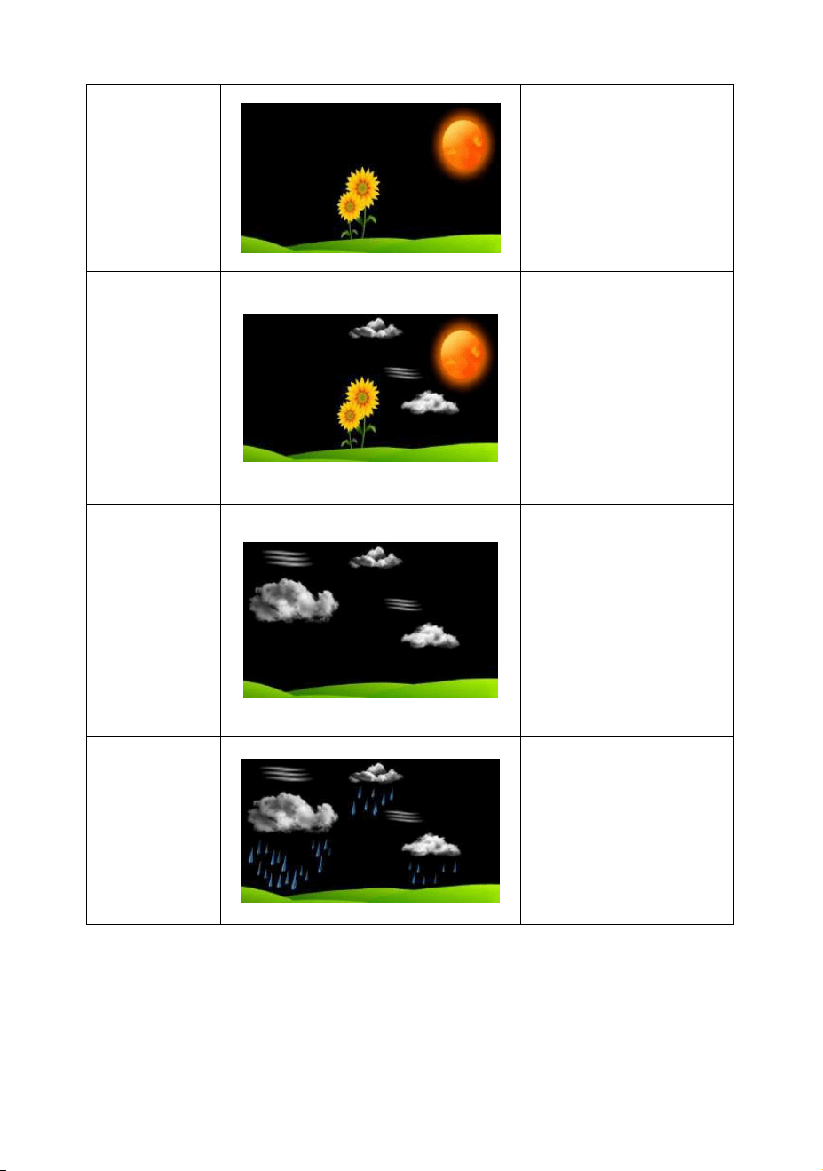
- 48 -
Sunny
Pressure is rising
and the previous
condition is partly
cloudy.
Partly
Cloudy
Pressure is falling
and the previous
condition is sunny
or Pressure is
rising and the
previous condition
is cloudy
Cloudy
Pressure is falling
and the previous
condition is partly
cloudy or Pressure
is rising and the
previous condition
is rainy.
Rainy
Pressure is falling
and the previous
condition is cloudy
10.3 Moon Phase
The following moon phases are displayed based on the
calendar date.
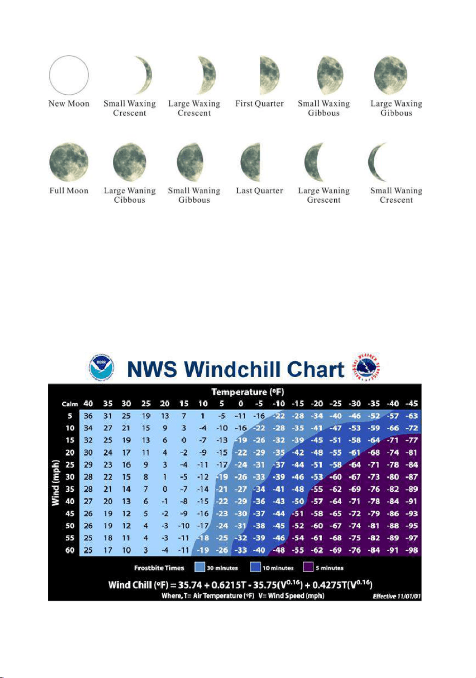
- 49 -
10.4 Feels Like and AT Temperature
10.4.1 Feels Like Temperature
Feels like temperature is a combination of Heat Index and
Wind Chill.
1. Temperatures less than 4.4°C(40°F), the wind chill is
displayed, as shown in the National Weather Service Wind
Chill Table below:
- 50 -
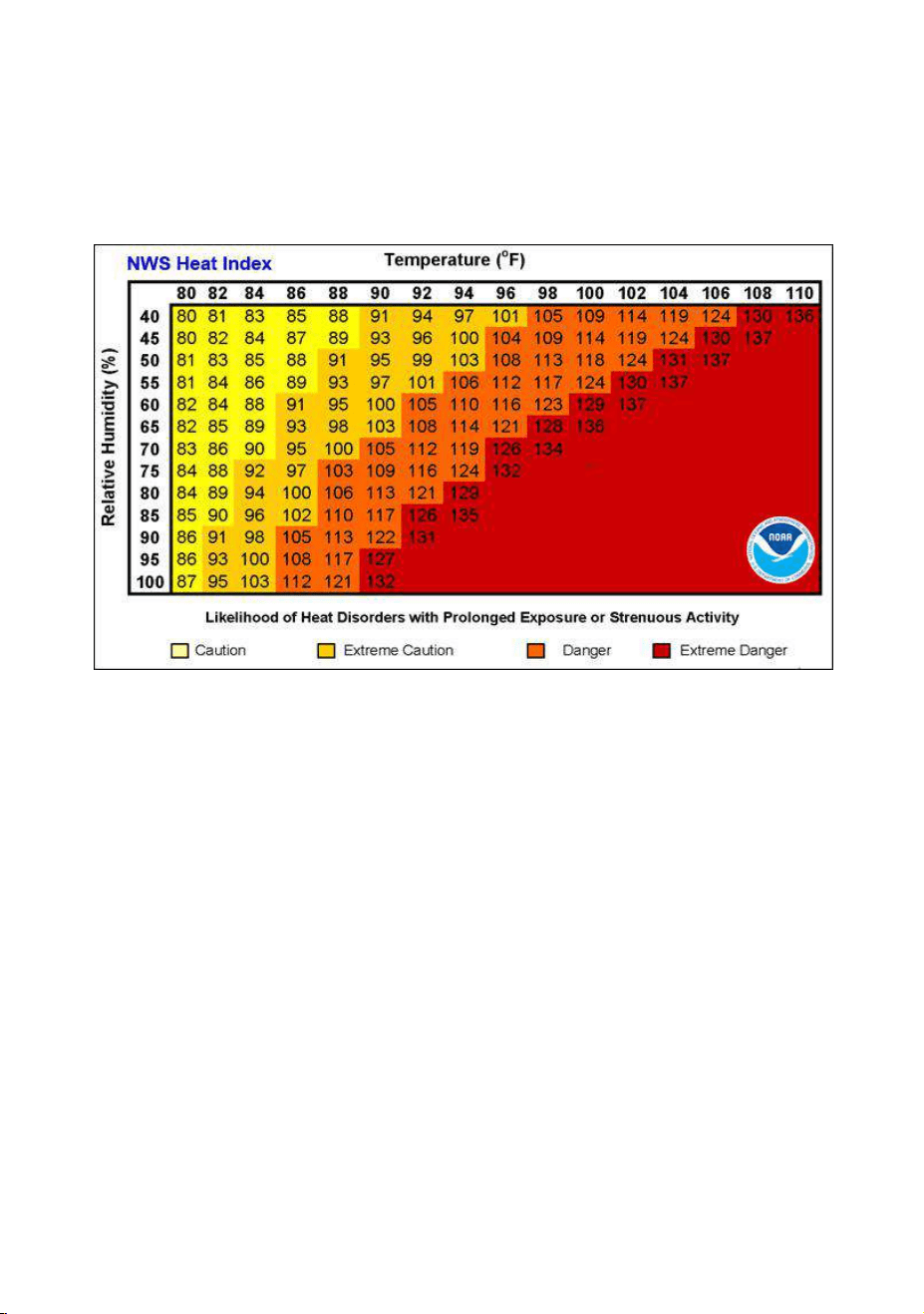
2. Temperatures greater than 26.7°C(80°F), the heat index
is displayed, as shown in the National Weather Service Heat
Index Table below:
10.4.2 Apparent Temperature (AT)
AT is a linear regression that is not restricted, and is more
appropriate to outside conditions because it includes wind, and
was intended as an assessment of what exposed body
surfaces feel like in cold, windy conditions
Regression equations of this universal scale are formulated for
indoors, outdoors in shade but exposed to wind, and outdoors
exposed to wind and solar radiation. Of these, outdoors in
shade but exposed to wind, has been chosen as most
informative.

- 51 -
10.5 Pressure Threshold Setting
The pressure threshold (the negative or positive rate of change
of pressure signifying a change in the weather) can be
adjusted from 2 hPa to 4 hPa (default level 2 hPa).
The lower the level pressure threshold setting, the higher
sensitivity for weather forecast changes. Locations that
experience frequent changes in air pressure require a higher
setting compared to locations where the air pressure is
typically stagnant.
10.6 Restore Factory Default
To reset the display console to factory default (WiFi network,
Weather server and display), press the MAX/MIN/- key while
plugging in power adaptor at the same time (Take out batteries
before starting the reset operation).
11. Maintenance
Clean the rain gauge of Integrated Outdoor Transmitter once
every 3 months.
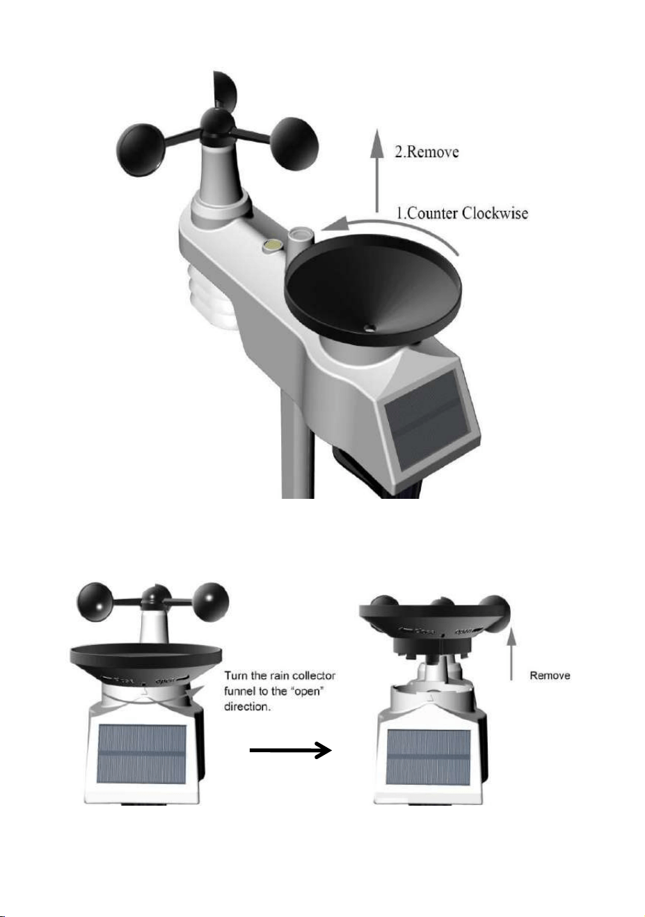
Unscrew the rain collector funnel by turning it 30°counter
clockwise.
Gently remove the rain collector funnel.
Clean and remove any debris or insects.
Install the collector funnel after it has been cleaned and
completely dried.
- 52 -
A. Remove the rain collector funnel
- 53 -
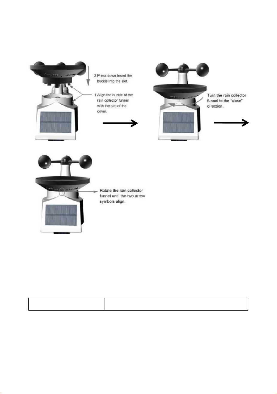
B. Install the collector funnel.
Replace the Integrated outdoor sensor and thermo-hygrometer
sensor batteries once every 1-2 years
12. Trouble Shooting Guide
Problem
Solution

- 54 -
Wireless remote
not reporting in to
console.
There are dashes
(--.-) on the display
console.
If any of the sensor communication is
lost, dashes (--.-) will be displayed on
the screen. To reacquire the signal,
press and hold the CHANNEL/+ button
for 3 seconds, choose the lost sensor
and the remote search icon will be
constantly displayed. Once the signal
is reacquired, the remote search
icon will turn off, and the current
values will be displayed.
The maximum line of sight
communication range is 100m (330ft)
and 30m(100ft) under most conditions.
Move the sensor assembly closer to
the display console.
If the sensor assembly is too close
(less than 1.5m(5ft)), move the sensor
assembly away from the display
console.
Make sure the remote sensor LCD
display is working and the transmitter
light is flashing once per 60 seconds.
Install a fresh set of batteries in the
remote thermo-hygrometer. For cold
weather environments, install lithium
batteries.
- 55 -
Make sure the remote sensors are not
transmitting through solid metal (acts
as an RF shield), or earth barrier
(down a hill).
Move the display console around
electrical noise generating devices,
such as computers, TVs and other
wireless transmitters or receivers.
Move the remote sensor to a higher
location. Move the remote sensor to a
closer location.
Temperature
sensor reads too
high in the day
time.
Make sure the thermo-hygrometer is
mounted in a shaded area. The pre
preferred location is a north facing wall
because it is in the shade most of the
day.
Indoor and Outdoor
Temperature do
not agree
Allow up to one hour for the sensors to
stabilize due to signal filtering. The
indoor and outdoor temperature
sensors should agree within 2°C
(4°F)(the sensor accuracy is ± 1°C(±
2°F)).
Use the calibration feature to match
the indoor and outdoor temperature to
a known source.
Indoor and Outdoor
Allow up to one hour for the sensors to
- 56 -
Humidity do not
agree
stabilize due to signal filtering. The
indoor and outdoor humidity sensors
should agree within 10 % (the sensor
accuracy is ± 5 %).
Use the calibration feature to match
the indoor and outdoor humidity to a
known source.
Display console
contrast is weak
Replace console batteries with a fresh
set of batteries.
13. Specification
13.1 Measurement Specifications
The following table provides specifications for the measured
parameters.
Measurement
Range
Accuracy
Resolution
Indoor
Temperature
0 to 60 °C
(32 to 140°F)
± 1 °C
(± 2°F)
0.1 °C(°F)
Outdoor
Temperature
-40 to 60 °C
(-40 to 140°F)
± 1 °C
(± 2°F))
0.1 °C(°F)
Indoor Humidity
10 to 99 %
± 5% (only
guaranteed
between 20
to 90%)
1 %
- 57 -
Outdoor
Humidity
10 to 99%
± 5% (only
guaranteed
between 20
to 90%)
1 %
Sensors 1-8
Temperature
-40 to 60 °C
(-40 to 140°F)
± 1 °C
(± 2°F))
0.1 °C(°F)
Sensors 1-8
Humidity
10 to 99%
± 5% (only
guaranteed
between 20
to 90%)
1 %
UV Index
1 to 15+
± 1
± 1
Sunlight
0 to 200klux
± 15%
± 15%
Rain
0 to 9999mm
<15mm:
±1 mm,
15mm to
9999mm:
±7%
<1000mm
(0.3mm)
>1000mm
(1mm)
Wind Direction
0 - 360º
± 10º (16
point
compass)
± 1º (16
point
compass)
Wind Speed
0 to 50 m/s
2 m/s ~10
m/s:±0.3m/s
, 10m/s ~50
m/s: ±10%
(whichever
is greater)
0.1 m/s
- 58 -
13.2 Wireless Specifications
Wireless Transmit Range (in open air):
330ft
(100m)
Frequency:
433MHz
Thermo-hygrometer Sensor Data Update
Period:
60s
Integrated Outdoor Sensor Data Update Period:
16s
13.3 Power Consumption
Display Console
3 x AAA 1.5V Alkaline or Lithium
batteries (not included)
Thermo-hygrometer
Sensor :
2 x AAA alkaline batteries or Lithium
batteries (not included)
Integrated Outdoor
Sensor:
3xAA alkaline batteries or Lithium
batteries (not included), the batteries
provide backup power when there is
limited solar energy.
Note: Solar panel doesn't charge the
battery and it is an auxiliary power
supply
Adapter:
6V~500mA(included)
Battery life:
Minimum 12 months for base station
with excellent reception. Intermittent
reception may reduce the battery life.
Minimum 12 months for sensors (use
Barometric
Pressure:
300 to 1100
hpa
± 3 hpa
0.1 hpa

- 59 -
lithium batteries in cold weather
climates less than -20°C(-4°F).