
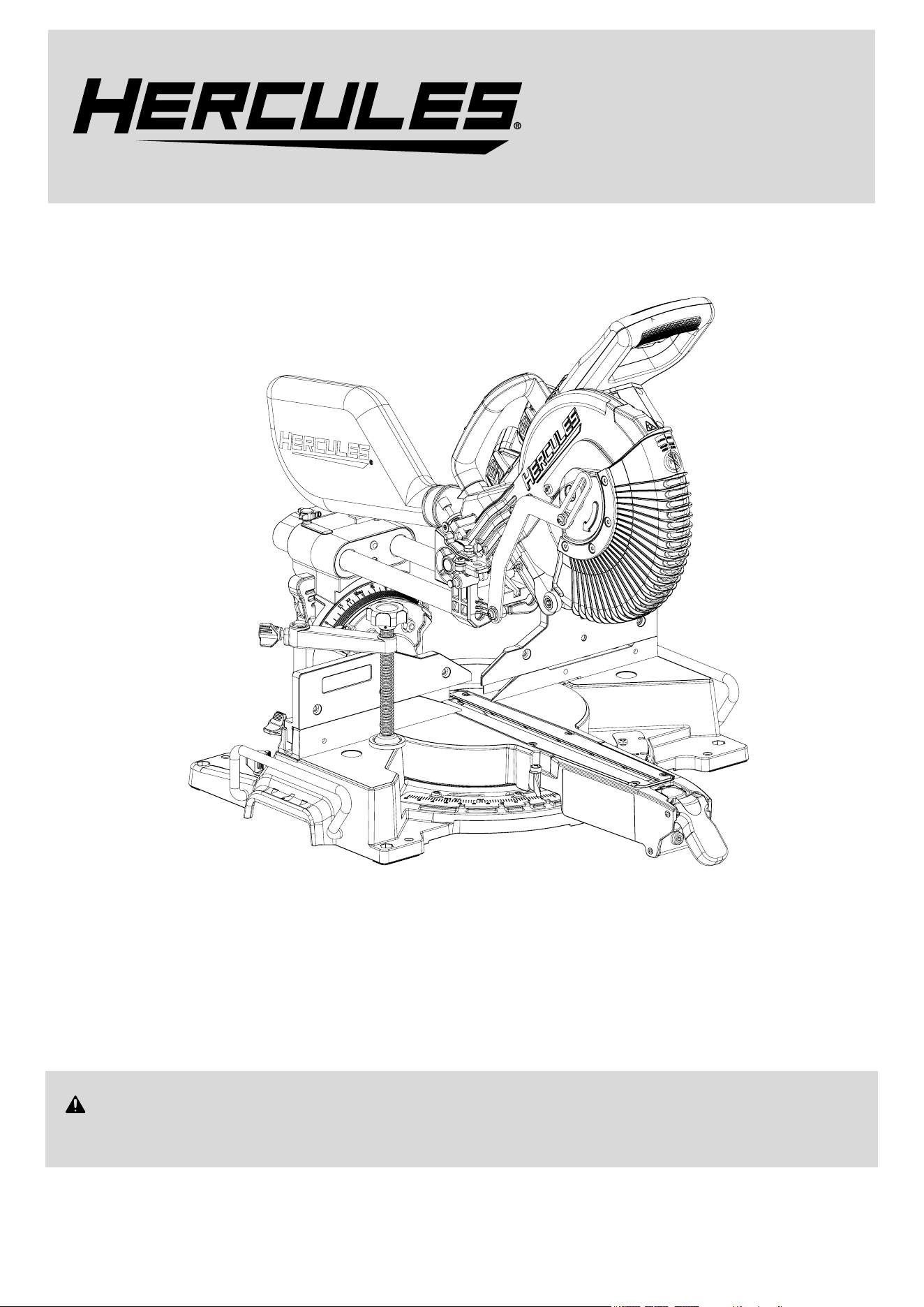
20V Brushless 10″ Double-Bevel Sliding Compound Miter Saw
Model
HE74B
WARNING: To prevent serious injury, User must read and
understand Owner’s Manual. SAVE THIS MANUAL.
When unpacking, make sure that the product is intact and undamaged.
If any parts are missing or broken, please call 1-888-866-5797
as soon as possible. Reference 57670.
Owner’s Manual &
Safety Instructions
23l
Requires 2 Batteries and Charger, Sold Separately

Page 2 For technical questions, please call 1-888-866-5797. Item 57670
IMPORTANT SAFETY INFORMATION
GENERAL POWER TOOL SAFETY WARNINGS
Read all safety warnings, instructions, illustrations
and specifications provided with this power tool.
Failure to follow all instructions listed below may
result in electric shock, fire and/or serious injury.
Save all warnings and instructions
for future reference.
The term “power tool” in the warnings refers
to your mains-operated (corded) power tool or
battery-operated (cordless) power tool.
Work area safety
1. Keep work area clean and well lit.
Cluttered or dark areas invite accidents.
2. Do not operate power tools in explosive
atmospheres, such as in the presence of
flammable liquids, gases or dust. Power tools
create sparks which may ignite the dust or fumes.
3. Keep children and bystanders away
while operating a power tool. Distractions
can cause you to lose control.
Electrical safety
1. Power tool plugs must match the outlet.
Never modify the plug in any way. Do not use
any adapter plugs with earthed (grounded)
power tools. Unmodified plugs and matching
outlets will reduce risk of electric shock.
2. Avoid body contact with earthed or grounded
surfaces, such as pipes, radiators, ranges and
refrigerators. There is an increased risk of electric
shock if your body is earthed or grounded.
3. Do not expose power tools to rain or wet
conditions. Water entering a power tool
will increase the risk of electric shock.
4. Do not abuse the cord. Never use the cord
for carrying, pulling or unplugging the power
tool. Keep cord away from heat, oil, sharp
edges or moving parts. Damaged or entangled
cords increase the risk of electric shock.
5. When operating a power tool outdoors,
use an extension cord suitable for outdoor
use. Use of a cord suitable for outdoor
use reduces the risk of electric shock.
6. If operating a power tool in a damp location
is unavoidable, use a ground fault circuit
interrupter (GFCI) protected supply. Use of
a GFCI reduces the risk of electric shock.
Personal safety
1. Stay alert, watch what you are doing and use
common sense when operating a power tool.
Do not use a power tool while you are tired
or under the influence of drugs, alcohol or
medication. A moment of inattention while operating
power tools may result in serious personal injury.
2. Use personal protective equipment. Always
wear eye protection. Protective equipment
such as dust mask, non-skid safety shoes, hard
hat, or hearing protection used for appropriate
conditions will reduce personal injuries.
3. Prevent unintentional starting. Ensure the
switch is in the off-position before connecting
to power source and/or battery pack, picking
up or carrying the tool. Carrying power tools
with your finger on the switch or energizing power
tools that have the switch on invites accidents.
4. Remove any adjusting key or wrench
before turning the power tool on. A wrench
or a key left attached to a rotating part of the
power tool may result in personal injury.
5. Do not overreach. Keep proper footing and
balance at all times. This enables better control
of the power tool in unexpected situations.
6. Dress properly. Do not wear loose clothing or
jewelry. Keep your hair, clothing and gloves
away from moving parts. Loose clothes, jewelry
or long hair can be caught in moving parts.
7. If devices are provided for the connection of
dust extraction and collection facilities, ensure
these are connected and properly used. Use of
dust collection can reduce dust-related hazards.
8. Do not let familiarity gained from frequent use
of tools allow you to become complacent and
ignore tool safety principles. A careless action can
cause severe injury within a fraction of a second.
9. Only use safety equipment that has been approved
by an appropriate standards agency. Unapproved
safety equipment may not provide adequate
protection. Eye protection must be ANSI-approved
and breathing protection must be NIOSH-approved
for the specific hazards in the work area.
10. Do not leave the tool unattended when the
Battery Pack is connected. Turn off the tool,
and remove the Battery Pack before leaving.
11. This product is not a toy.
Keep it out of reach of children.

Page 3For technical questions, please call 1-888-866-5797.Item 57670
12. People with pacemakers should consult their
physician(s) before use. Electromagnetic fields in
close proximity to heart pacemaker could cause
pacemaker interference or pacemaker failure.
13. The warnings, precautions, and instructions
discussed in this instruction manual cannot
cover all possible conditions and situations
that may occur. It must be understood by the
operator that common sense and caution are
factors which cannot be built into this product,
but must be supplied by the operator.
Power tool use and care
1. Do not force the power tool. Use the correct
power tool for your application. The correct
power tool will do the job better and safer
at the rate for which it was designed.
2. Do not use the power tool if the switch
does not turn it on and off. Any power
tool that cannot be controlled with the switch
is dangerous and must be repaired.
3. Disconnect the plug from the power source and/
or remove the battery pack, if detachable, from
the power tool before making any adjustments,
changing accessories, or storing power
tools. Such preventive safety measures reduce
the risk of starting the power tool accidentally.
4. Store idle power tools out of the reach of
children and do not allow persons unfamiliar
with the power tool or these instructions
to operate the power tool. Power tools are
dangerous in the hands of untrained users.
5. Maintain power tools and accessories.
Check for misalignment or binding of moving
parts, breakage of parts and any other
condition that may affect the power tool’s
operation. If damaged, have the power tool
repaired before use. Many accidents are
caused by poorly maintained power tools.
6. Keep cutting tools sharp and clean. Properly
maintained cutting tools with sharp cutting edges
are less likely to bind and are easier to control.
7. Use the power tool, accessories and tool bits
etc. in accordance with these instructions,
taking into account the working conditions
and the work to be performed. Use of the
power tool for operations different from those
intended could result in a hazardous situation.
8. Keep handles and grasping surfaces dry, clean
and free from oil and grease. Slippery handles
and grasping surfaces do not allow for safe handling
and control of the tool in unexpected situations.
Service
1. Have your power tool serviced by a
qualified repair person using only identical
replacement parts. This will ensure that the
safety of the power tool is maintained.
2. Never service damaged BATTERY packs. Service
of BATTERY packs should only be performed by
the manufacturer or authorized service providers.
3. Maintain labels and nameplates on the tool.
These carry important safety information.
If unreadable or missing, contact
Harbor Freight Tools for a replacement.
Safety instructions for mitre saws
1. Mitre saws are intended to cut wood or wood-like
products, they cannot be used with abrasive
cut-off wheels for cutting ferrous material such
as bars, rods, studs, etc. Abrasive dust causes
moving parts such as the lower guard to jam.
Sparks from abrasive cutting will burn the lower
guard, the kerf insert and other plastic parts.
2. Use clamps to support the workpiece whenever
possible. If supporting the workpiece by hand,
you must always keep your hand at least 100
mm from either side of the saw blade. Do not
use this saw to cut pieces that are too small to
be securely clamped or held by hand. If your
hand is placed too close to the saw blade, there
is an increased risk of injury from blade contact.
3. The workpiece must be stationary and
clamped or held against both the fence
and the table. Do not feed the workpiece
into the blade or cut ″freehand″ in any way.
Unrestrained or moving workpieces could be
thrown at high speeds, causing injury.
4. Push the saw through the workpiece. Do
not pull the saw through the workpiece. To
make a cut, raise the saw head and pull it out
over the workpiece without cutting, start the
motor, press the saw head down and push
the saw through the workpiece. Cutting on
the pull stroke is likely to cause the saw blade to
climb on top of the workpiece and violently throw
the blade assembly towards the operator.
5. Never cross your hand over the intended line of
cutting either in front or behind the saw blade.
Supporting the workpiece ″cross handed″ i.e. holding
the workpiece to the right of the saw blade with
your left hand or vice versa is very dangerous.
6. Do not reach behind the fence with either hand
closer than 100 mm from either side of the saw
blade, to remove wood scraps, or for any other
reason while the blade is spinning. The proximity
of the spinning saw blade to your hand may not
be obvious and you may be seriously injured.

Page 4 For technical questions, please call 1-888-866-5797. Item 57670
7. Inspect your workpiece before cutting. If the
workpiece is bowed or warped, clamp it with
the outside bowed face toward the fence.
Always make certain that there is no gap
between the workpiece, fence and table along
the line of the cut. Bent or warped workpieces
can twist or shift and may cause binding on the
spinning saw blade while cutting. There should
be no nails or foreign objects in the workpiece.
8. Do not use the saw until the table is clear
of all tools, wood scraps, etc., except for
the workpiece. Small debris or loose pieces of
wood or other objects that contact the revolving
blade can be thrown with high speed.
9. Cut only one workpiece at a time. Stacked multiple
workpieces cannot be adequately clamped or braced
and may bind on the blade or shift during cutting.
10. Ensure the mitre saw is mounted or placed
on a level, firm work surface before use.
A level and firm work surface reduces the
risk of the mitre saw becoming unstable.
11. Plan your work. Every time you change the bevel
or mitre angle setting, make sure the adjustable
fence is set correctly to support the workpiece
and will not interfere with the blade or the
guarding system. Without turning the tool ″ON″ and
with no workpiece on the table, move the saw blade
through a complete simulated cut to assure there will
be no interference or danger of cutting the fence.
12. Provide adequate support such as table
extensions, saw horses, etc. for a workpiece
that is wider or longer than the table top.
Workpieces longer or wider than the mitre saw
table can tip if not securely supported. If the cut-
off piece or workpiece tips, it can lift the lower
guard or be thrown by the spinning blade.
13. Do not use another person as a substitute for a
table extension or as additional support. Unstable
support for the workpiece can cause the blade to bind
or the workpiece to shift during the cutting operation
pulling you and the helper into the spinning blade.
14. The cut-off piece must not be jammed or
pressed by any means against the spinning
saw blade. If confined, i.e. using length
stops, the cut-off piece could get wedged
against them blade and thrown violently.
15. Always use a clamp or a fixture designed
to properly support round material such as
rods or tubing. Rods have a tendency to roll
while being cut, causing the blade to ″bite″ and
pull the work with your hand into the blade.
16. Let the blade reach full speed before
contacting the workpiece. This will reduce
the risk of the workpiece being thrown.
17. If the workpiece or blade becomes jammed, turn
the mitre saw off. Wait for all moving parts to
stop and disconnect the plug from the power
source and/or remove the battery pack. Then
work to free the jammed material. Continued
sawing with a jammed workpiece could cause
loss of control or damage to the .mitre saw.
18. After finishing the cut, release the switch, hold
the saw head down and wait for the blade to stop
before removing the cut-off piece. Reaching with
your hand near the coasting blade is dangerous.
19. Hold the handle firmly when making an
incomplete cut or when releasing the switch
before the saw head is completely in the
down position. The braking action of the
saw may cause the saw head to be suddenly
pulled downward, causing a risk of injury.
Battery tool use and care
1. Prevent unintentional starting. Ensure the switch is
in the off-position before connecting to battery pack,
picking up or carrying the power tool. Carrying the
power tool with your finger on the switch or energizing
power tool that have the switch on invites accidents.
2. Disconnect the battery pack from the
power tool before making any adjustments,
changing accessories, or storing power tool.
Such preventive safety measures reduce the
risk of starting the power tool accidentally.
3. Recharge only with the charger specified by
the manufacturer. A charger that is suitable
for one type of battery pack may create a risk
of fire when used with another battery pack.
4. Use power tools only with specifically
designated battery packs. Use of any other
battery packs may create a risk of injury and fire.
5. When battery pack is not in use, keep it away
from other metal objects, like paper clips,
coins, keys, nails, screws or other small metal
objects, that can make a connection from
one terminal to another. Shorting the battery
terminals together may cause burns or a fire.
6. Under abusive conditions, liquid may be ejected
from the battery; avoid contact. If contact
accidentally occurs, flush with water. If liquid contacts
eyes, additionally seek medical help. Liquid ejected
from the battery may cause irritation or burns.
7. Do not use a battery pack or power tool that
is damaged or modified. Damaged or modified
batteries may exhibit unpredictable behavior
resulting in fire, explosion or risk of injury.
8. Do not expose a battery pack or power tool to
fire or excessive temperature. Exposure to fire or
temperature above 140°F may cause explosion.
Page 5For technical questions, please call 1-888-866-5797.Item 57670
9. Follow all charging instructions and do
not charge the battery pack or power tool
outside of the temperature range specified
in the instructions. Charging improperly or at
temperatures outside of the specified range may
damage the battery and increase the risk of fire.
10. Have servicing performed by a qualified
repair person using only identical
replacement parts. This will ensure that
the safety of the product is maintained.
11. Do not modify or attempt to repair the power
tool or the battery pack except as indicated
in the instructions for use and care.
12. The battery Charger gets hot during use.
The Charger’s heat can build up to unsafe
levels and create a fire hazard if it does
not receive adequate ventilation, due to
an electrical fault, or if it is used in a hot environment.
Do not place the Charger on a flammable surface.
Do not obstruct any vents on the Charger.
Especially avoid placing the Charger on carpets
and rugs; they are not only flammable, but they
also obstruct vents under the Charger. Place the
Charger on a stable, solid, nonflammable surface
(such as a stable metal workbench or concrete floor)
at least 1 foot away from all flammable objects, such
as drapes or walls. Keep a fire extinguisher and a
smoke detector in the area. Frequently monitor the
Charger and Battery Pack while charging.
13. Lithium Battery Safety Warnings
LITHIUM BATTERIES STORE
A LARGE AMOUNT OF ENERGY AND
WILL VENT FIRE OR EXPLODE
IF MISTREATED:
a. Keep Battery Pack dry.
b. DO NOT DO ANY OF THE FOLLOWING
TO THE BATTERY PACK:
• Open,
• Drop,
• Short-circuit,
• Puncture,
• Incinerate, or
• Expose to temperatures greater than 140°F.
c. Charge Battery Pack only according
to its Charger’s instructions.
d. Inspect Battery Pack before every use;
do not use or charge if damaged.
Vibration Safety
This tool vibrates during use.
Repeated or long-term exposure to vibration may
cause temporary or permanent physical injury,
particularly to the hands, arms and shoulders.
To reduce the risk of vibration-related injury:
a. Anyone using vibrating tools regularly or for an
extended period should first be examined by a
doctor and then have regular medical check-ups
to ensure medical problems are not being caused
or worsened from use. Pregnant women or
people who have impaired blood circulation to
the hand, past hand injuries, nervous system
disorders, diabetes, or Raynaud’s Disease should
not use this tool. If you feel any medical or
physical symptoms related to vibration (such as
tingling, numbness, and white or blue fingers),
seek medical advice as soon as possible.
b. Do not smoke during use. Nicotine reduces
the blood supply to the hands and fingers,
increasing the risk of vibration-related injury.
c. Use tools with the lowest vibration when there
is a choice between different processes.
d. Include vibration-free periods each day of work.
e. Grip workpiece as lightly as possible
(while still keeping safe control of it).
Let the tool do the work.
f. To reduce vibration, maintain the tool as
explained in this manual. If any abnormal
vibration occurs, stop use immediately.
GROUNDING
TO PREVENT ELECTRIC SHOCK AND
DEATH FROM INCORRECT GROUNDING:
Check with a qualified electrician if you are
in doubt as to whether the outlet is
properly grounded. Do not modify the power cord
plug provided with the charger. Do not use the
charger if the power cord or plug is damaged.
If damaged, have it repaired by a service facility
before use. If the plug will not fit the outlet,
have a proper outlet installed by a
qualified electrician.
Extension Cords
Note: Extension cords must not be
used with this item’s Charger.
Page 6 For technical questions, please call 1-888-866-5797. Item 57670
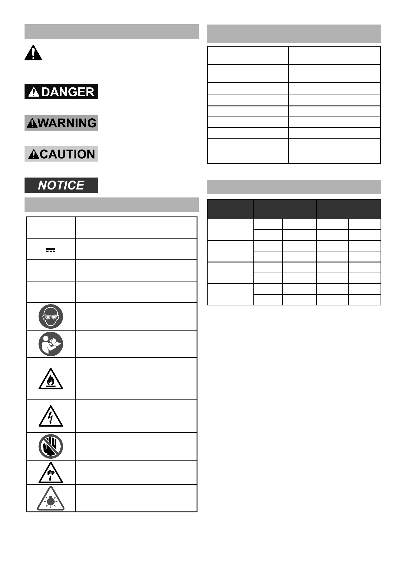
Warning Symbols and Definitions
This is the safety alert symbol. It is used to
alert you to potential personal injury hazards.
Obey all safety messages that follow this symbol to
avoid possible injury or death.
Indicates a hazardous
situation which, if not
avoided, will result in death or serious injury.
Indicates a hazardous
situation which, if not
avoided, could result in death or serious injury.
Indicates a hazardous
situation which, if not
avoided, could result in minor or moderate injury.
Addresses practices not
related to personal injury.
Symbology
V
Volts
Direct Current
A
Amperes
n
0
xxxx/min.
No Load Revolutions per Minute (RPM)
WARNING marking concerning Risk
of Eye Injury. Wear ANSI-approved
safety goggles with side shields.
Read the manual before set-up and/or use.
WARNING marking
concerning Risk of Fire.
Do not cover Charger
ventilation ducts.
Charge on fireproof surface only.
WARNING marking concerning
Risk of Electric Shock.
Properly connect Charger’s power
cord to appropriate outlet.
Keep hands clear of fence area.
DANGER marking concerning
Risk of Amputation.
Keep hands well clear of cutting area.
Bright Light.
To prevent eye injury,
do not stare into light.
SPECIFICATIONS
Battery Type
Hercules 20V Li-Ion
57373 (sold separately)*
Charger Type
Hercules 20V Li-Ion
56559 (sold separately)
Electrical Rating 40VDC
Spindle No Load Speed n
0
: 4200/min
Blade Diameter
10"
Arbor 5/8" Round
Maximum Blade Kerf 0.13"
Capacity of Cut
50° Miter Left
60° Miter Right
45° Bevel Left and Right
*Requires two 20V batteries
Cutting Capacities
ANGLE FRONT FENCE REAR FENCE
0° Miter
Height 3-9/16" Height 2-9/16"
Width 12-1/8" Width 15-1/8"
45° Miter
Height 3-9/16" Height 2-9/16"
Width 8-5/8" Width 11-5/8"
45° Bevel
Left
Height 2-3/8" Height 7/8"
Width 12-1/4" Width 15-3/4"
45° Bevel
Right
Height 1-1/2" Height 1/2"
Width 12-1/8" Width 15-3/4"
Page 7For technical questions, please call 1-888-866-5797.Item 57670
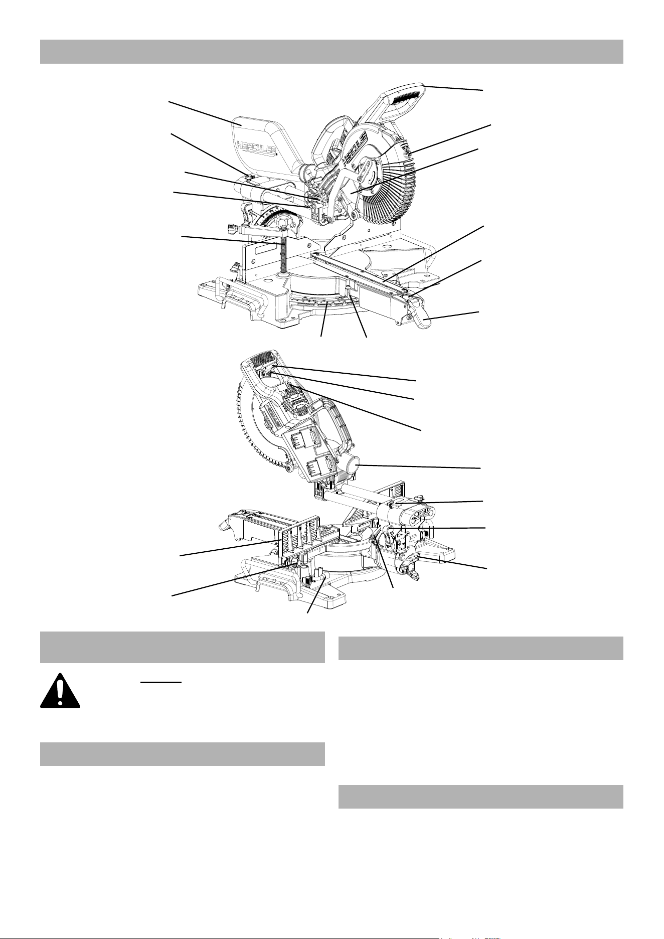
Functional Description
Bevel
Angle
Indicator
Bevel
Detent
Lever
Bevel
Lock
Knob
Fence Lock
Knob
Dust Outlet
Blade Guide
Switch
Fence
Trigger
Wrench
Depth Stop
Head
Lock-Down
Pin
Dust
Collection
Bag
Slide Lock
Knob
Blade
Lower Blade
Guard
Clamp
Miter Lock
Lever
Miter
Scale
Kerf
Board
TurntableTurntable
Miter
Detent
Button
Miter Angle
Indicator
Slide
Stop
Handle
Trigger
Lock
SETUP - BEFORE USE:
Read the ENTIRE IMPORTANT
SAFETY INFORMATION section at the
beginning of this manual including
all text under subheadings therein
before set up or use of this product.
Charging
Charge battery packs after unpacking and
before using this tool. Follow instructions
included with battery charger.
Installing and Removing Batteries
1. Fully charge batteries.
2. Check fuel gauges by pressing buttons on back of
batteries. Four lights equal 100%. Three lights equal
75%. Two lights equal 50%. One light equals 25%.
3. Install two batteries into top of Handle,
making sure they click in place securely.
4. To remove batteries, press release
buttons and remove batteries.
Assembly
Slip Dust Collection Bag over Bracket
and Dust Outlet behind the saw.
Page 8 For technical questions, please call 1-888-866-5797. Item 57670
Mounting
1. Use bolt holes in Base to mount Miter
Saw to a stable support before use.
Note: Mounting holes are provided in two sizes
to accommodate different sizes of hardware.
Mounting hardware sold separately.
2. Ensure miter saw is always stable and
secure (e.g. fixed to a bench).
Saw Blade Selection
1. Any saw blade that will be used must be
marked as suitable for the material to be cut.
2. Use only a saw blade diameter in accordance
with the markings on the saw. See table
in Specifications for arbor diameter and
the maximum kerf of saw blade.
3. Use only saw blades marked with a speed equal
or higher than the speed marked on the tool.
Guard Setup
Check that the Lower Blade Guard is in place,
moves freely, and closes instantly.
OPERATING INSTRUCTIONS
Read the ENTIRE IMPORTANT
SAFETY INFORMATION section at the
beginning of this manual including
all text under subheadings therein
before set up or use of this product.
TO PREVENT SERIOUS INJURY FROM
ACCIDENTAL OPERATION:
Make sure that the Trigger is in the off-position
and remove its Battery Packs before
performing any procedure in this section.
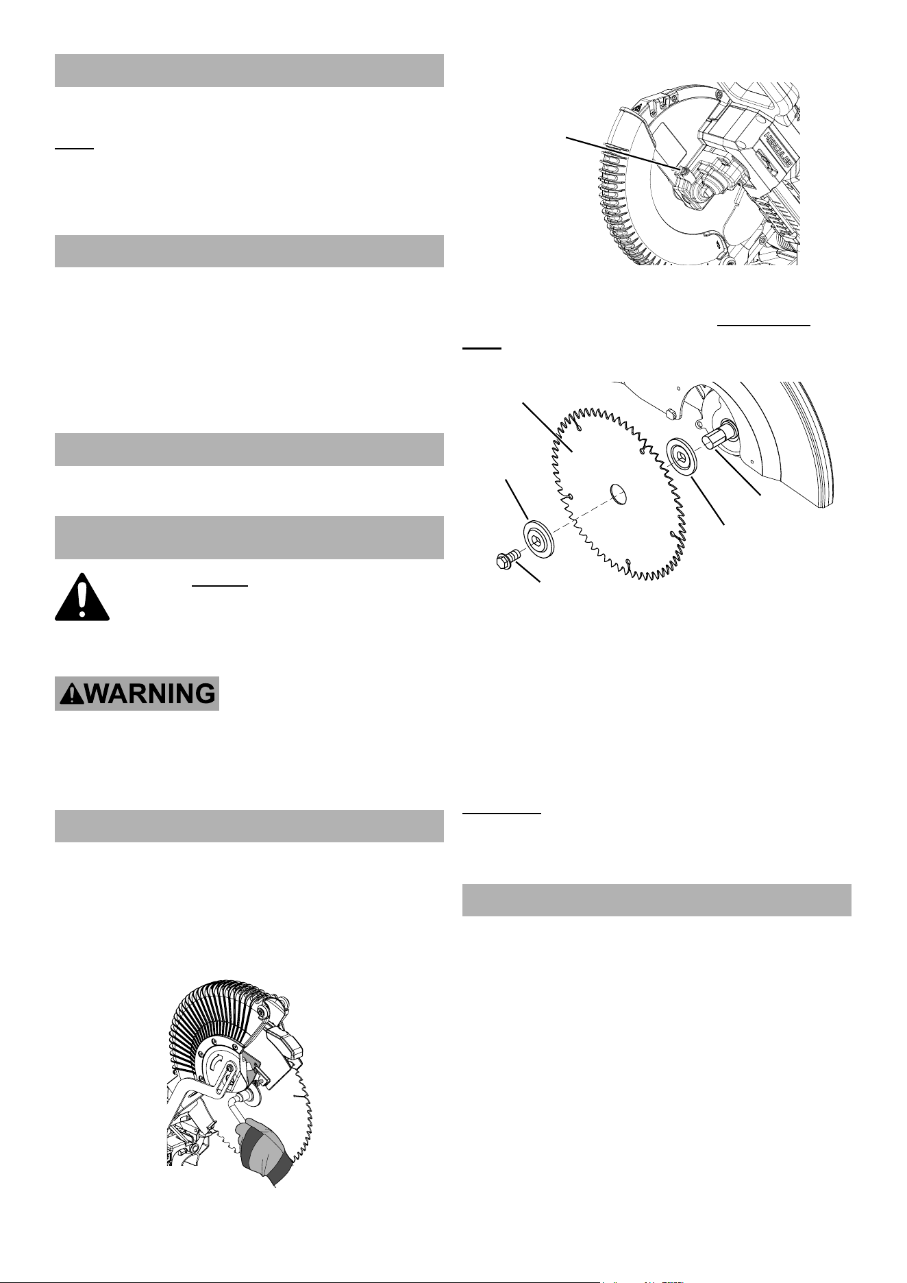
Tool Changing
1. Remove battery packs.
2. Pull out Head Lock-Down Pin, raise Saw
Head to upper position, then raise Lower
Blade Guard out of the way and hold it up.
3. Loosen Guard Plate Screw until disengaged from
Guard Plate. Swing Guard Plate up and out of way.
4. Press in Spindle Lock and hold it in.
Spindle
Lock
5. Remove Arbor Bolt and Outer Flange.
IMPORTANT: The Arbor Bolt has a left-handed
thread and removes by turning CLOCKWISE.
Note: Make sure Inner Flange stays
in place on the Spindle.
Outer
Flange
Inner
Flange
Spindle
Blade
Arbor Bolt
6. If replacing a used blade, remove blade.
Install new Blade. Make sure that Blade’s
rotation arrow points in same direction as
rotation arrow on Lower Blade Guard.
7. Replace Outer Flange and Arbor Bolt. Position
cupped side of Flange against blade.
Hold in Spindle Lock and wrench tighten Arbor Bolt
by turning it counterclockwise. Release Spindle Lock.
8. Rotate Guard Plate back into place and
secure it with Guard Plate Bolt.
WARNING! TO PREVENT SERIOUS
INJURY: Make sure the Lower Blade Guard
operates smoothly and properly protects
from the Blade before using the saw.
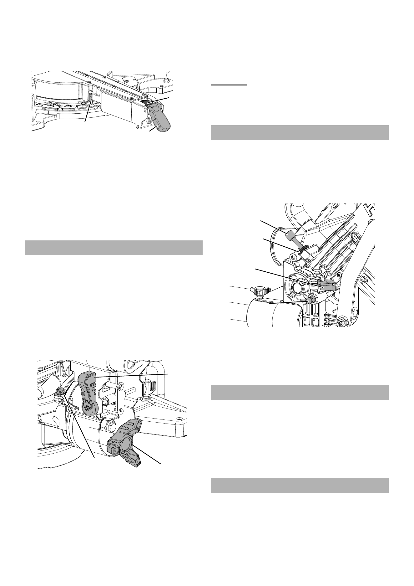
Adjusting the Miter Angle
A miter cut is one that is at an angle across the horizontal
surface of the material. 45º miter cuts to join two pieces
in a right angle corner are common. A 30º cut is often
used for a scarf joint or to make a chamfered end.
1. Pull up on Miter Detent Lever to unlock Turntable.
Press Miter Detent Button down, and
move Turntable to desired angle.
Page 9For technical questions, please call 1-888-866-5797.Item 57670
2. The Miter Angle Indicator will indicate the selected
angle. With Miter Detent Button released,
Turntable will lock into place at often used miter
angles, including 15º, 22.5º, 31.6º, and 45º on
left and right sides, and 60° on right side.
Miter Angle
Indicator
Miter
Detent
Button
Miter Lock
Lever
3. To override pre-set detents (stops) for micro
adjustments at any angle, pull up on Miter Detent
Lever and press Miter Detent Button down and
forward to lock it out. Adjust Turntable to any position
on miter scale. Push Miter Detent Lever down to lock
in place. Pull Miter Detent Button back to release
and allow Turntable to lock into detent positions.
4. With Turntable adjusted to desired angle,
place workpiece flush against Fence, secure
it with Clamp, and make the cut.
Adjusting the Bevel Angle
A bevel cut is one that is at an angle vertically. Bevel
cuts can be used to miter relatively wide and thin
material. Bevel cuts can be used in combination with
a miter cut to form a compound angle. Compound
angle cuts are often used in crown moldings,
picture frames and similar trim materials.
1. Loosen Bevel Lock Knob at rear of saw.
2. For micro adjustments at any bevel angle, push
the Bevel Detent Lever back until it snaps into
place and move Saw Head Assembly to desired
angle. Read angle on the Bevel Angle Indicator.
Bevel
Angle
Indicator
Bevel
Detent
Lever
Lever
Bevel
Lock
Knob
3. To use pre-set detents (stops), push Bevel Detent
Lever back until Saw Head Assembly can be moved
and then release Lever. Saw Head Assembly will
lock into place at often used bevel angles, including
22.5º, 33.9º, and 45º on both left and right sides.
4. Lock Saw Head Assembly into position
by rotating Bevel Lock Knob clockwise.
Tighten firmly but do not over-tighten.
5. Make a sample cut in a piece of scrap
to confirm that bevel angle is correct.
If it is not, correct angle before cutting.
WARNING! TO PREVENT SERIOUS INJURY:
Adjust both sides of the Fence clear of the Blade’s
cutting path after making any adjustment to the
cutting angle. Move the Blade through its full
range of motion to ensure the Fences are clear.
Using the Depth Stop
If a kerfing or rabbet cut which does not cut
through the workpiece is desired, use the
Depth Stop to control the depth of the cut.
1. Pull out Head Lock-Down Pin and
raise Saw Head Assembly.
2. Pull down on Saw Head to check current setting.
Depth
Depth
Adjustment
Adjustment
Knob
Knob
Thumb Nut
Depth
Stop
Head
Head
Lock-Down
Lock-Down
Pin
Pin
3. To change setting, first loosen Thumb Nut on
Depth Adjustment Knob. Pull Depth Stop outward.
Turn Depth Adjustment Knob clockwise to
increase depth and counterclockwise to decrease
depth. Tighten Thumb Nut after adjustment.
4. Push Depth Stop inward to disengage.
Aligning the Fence
1. After adjusting miter, bevel, or depth setting,
check and adjust both sides of fence.
2. Loosen one of the Fence Knobs, and move
its Sliding Fence to be within 1/8" of blade.
3. Tighten Fence Knob. Make sure Sliding
Fence still does not contact Blade.
4. Repeat process for other Fence
Knob and Sliding Fence.
Workpiece and Work Area Set Up
1. Designate a work area that is clean and well lit.
The work area must not allow access by children
or pets to prevent distraction and injury.
2. Secure loose workpieces using included Clamp
or other clamping devices (sold separately)
to prevent movement while working.
Page 10 For technical questions, please call 1-888-866-5797. Item 57670
3. There must not be objects, such as utility lines,
nearby that will present a hazard while working.
4. Cut only the following materials:
dimensional lumber, plywood, particle board, plastic.
Note: Use caution to avoid overheating the cutting tips.
If cutting plastic, cut at an even pace to avoid melting it.
5. Allow room on both left and right sides
of saw for extended workpieces.
6. Use additional supports if needed to ensure stability
of workpiece. Mount Saw so surface is level to
the ground, and additional supports to provide a
surface on same level as saw Turntable. If work
surface and any workpiece supports are not level,
and on same level, unwanted bevel angles will
appear in the cuts resulting in poor joinery.
7. Secure workpieces to saw Turntable using
included Clamp or other clamping devices
(sold separately). Securing workpiece will
provide safety by preventing kick back and by
removing the need to hold workpieces near the
blade by hand. Clamping the workpiece will
also improve cutting accuracy by preventing
workpiece from moving during cutting operation.
General Instructions for Use
1. Make sure that the Trigger is in the off-position,
then attach the Battery Packs.
Sliding Miter Saw Cutting Procedure:
2. Press Saw Head down and pull
out Head Lock-Down Pin.
3. Check all adjustment knobs are tight (Miter
Lock Lever, Bevel Lock Knob, and Fence).
4. Blow any sawdust or debris away from
Fence. Place workpiece against Fence.
5. Aligning cut WITH Blade Guide: Turn Blade
Guide switch to ON. Pull Saw Head down
close to workpiece until Blade shadow appears
on workpiece. Align marked location of cut
on workpiece with edge of Blade shadow.
6. Aligning cut WITHOUT Blade Guide: Align
marked location of cut on workpiece with Blade.
To prevent workpiece from being cut too short,
align edge of Blade with measured mark, keeping
remainder of Blade on waste side of cut.
7. Hold workpiece in place using Clamp. Ensure
workpiece is level and supported securely.
Use saw horses or supports if necessary.
DANGER! TO PREVENT SERIOUS
INJURY AND DEATH: Saws can quickly
amputate fingers if misused.
Keep hands well clear of cutting area.
8. Grip Saw Handle, simultaneously squeeze
Trigger Lock (small tab projecting from
Trigger) and Trigger to start the Saw.
9. Use one hand and hold workpiece securely
against Turntable and Fence at all times.
10. Narrow workpiece: Press down lightly
to cut workpiece. Press straight down,
“chopping” the material. Do not bear down
on material — use light downward pressure. If
material binds the Blade, release Trigger.
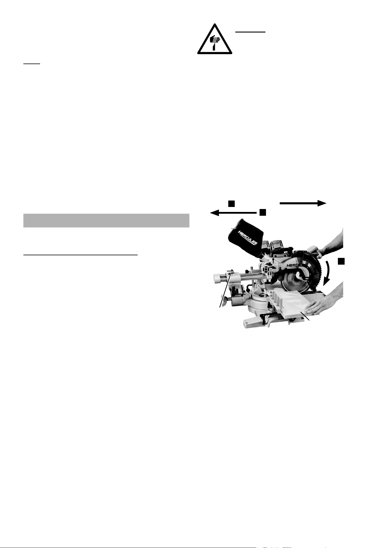
11. Wide workpiece: Move Blade across
workpiece while cutting as follows:
a. Loosen Slide Lock Knob and
pull Saw Head forward.
b. Press down Saw Handle.
c. Push Saw Head toward rear to cut.
Pull Forward
1
Push Toward Rear to Cut
3
Press
Press
Down
Down
2
Slide
Lock
Knob
d. Do not bear down on material — use light
downward and lateral pressure. If material
binds the Blade, release Trigger.
12. When cut is completed, raise Saw Head,
release Trigger, wait for Blade to stop turning,
release Clamp and remove workpiece.
13. To prevent accidents, turn off the tool and
remove its Battery Packs after use. Clean, then
store the tool indoors out of children’s reach.
14. Lock the head down and lock all other
adjustments before moving the saw. Use the
handle cut outs on each end of the Turntable
base to lift and support Saw while moving it.

Page 11For technical questions, please call 1-888-866-5797.Item 57670
MAINTENANCE AND
SERVICING INSTRUCTIONS
Procedures not specifically explained
in this manual must be performed
only by a qualified technician.
TO PREVENT SERIOUS INJURY FROM
ACCIDENTAL OPERATION:
Make sure that the Trigger is in the off-position
and remove its Battery Packs before
performing any procedure in this section.
TO PREVENT SERIOUS INJURY
FROM TOOL FAILURE: Do not use damaged
equipment. If abnormal noise or vibration occurs,
have the problem corrected before further use.
Cleaning, Maintenance,
and Lubrication
1. BEFORE EACH USE, inspect the general
condition of the tool. Check for:
• leaking, swollen, or cracked battery packs,
• loose hardware,
• misalignment or binding of moving parts,
• cracked or broken parts, and
• any other condition that may
affect its safe operation.
2. AFTER USE, wipe external surfaces of the tool with
clean cloth. Carefully clean the dust collection chute
and the area around the Lower Blade Guard. Check
that the Lower Blade Guard moves smoothly through
its entire range of movement, without sticking.
3. Li-Ion BATTERY MUST BE RECYCLED OR
DISPOSED OF PROPERLY.
Do not short, incinerate or open battery.
4. Disconnect battery packs and store battery
packs, charger, and tool in dry, indoor area out
of reach of children and away from metal objects
(i.e., paperclips, coins) to prevent shorting.
Troubleshooting
Problem Possible Causes Likely Solutions
Tool will not start. 1. Battery Packs not properly
connected.
2. Battery Packs not properly charged.
3. Battery Packs burnt-out.
4. Internal damage or wear.
(Trigger, for example.)
1. Remove Battery Pack, make sure there are no
obstructions, reinsert the Battery Packs according
to its shape (it should only fit one way), and press
firmly until the Battery Packs lock in place.
2. Make sure Charger is connected and
operating properly. Give enough time for
Battery Packs to recharge properly.
3. Dispose of old Battery Packs
properly or recycle. Replace Battery Packs.
4. Have technician service tool.
Tool operates slowly. 1. Forcing tool to work too fast.
2. Battery Packs wearing out.
1. Allow tool to work at its own rate.
2. Dispose of old Battery Packs
properly or recycle. Replace Battery Packs.
Excessive noise
or rattling.
Internal damage or wear
(bearings, for example).
Have technician service tool.
Overheating. 1. Forcing tool to work too fast.
2. Blocked motor housing vents.
1. Allow tool to work at its own rate.
2. Wear ANSI-approved safety goggles and
NIOSH-approved dust mask/respirator while
blowing dust out of motor using compressed air.
Follow all safety precautions whenever diagnosing or servicing the tool.
Disconnect Battery Packs and Charger power supply before service.
Record Product’s Serial Number Here:
Note: If product has no serial number, record month and year of purchase instead.
Note: Some parts are listed and shown for illustration purposes only, and are not available individually as
replacement parts. Visit harborfreight.com/parts for a list of in stock parts. Reference UPC 193175420879.

26677 Agoura Road • Calabasas, CA 91302 • 1-888-866-5797
5-YEAR LIMITED WARRANTY
This Hercules tool is warranted to the original purchaser to be free from defects in materials and workmanship
for a period of five (5) years beginning on the date of purchase. This warranty does not cover battery packs and
battery chargers, which are covered under separate warranties. To obtain warranty service, visit your local Harbor
Freight retail store. Warranty registration is not required. The product or part must be returned to us with proof of
purchase (e.g. in-store receipt or packing slip/invoice) and may require shipment by purchaser to a service center
at purchaser’s expense. If our inspection verifies a covered defect in materials or workmanship during the warranty
period, we will, at our option, repair or replace the defective product. We will return repaired products within a
reasonable time at our expense, but if we determine that there is no defect, or that the defect resulted from causes
not within the scope of our warranty, then we will return the product to you if you pay return shipping costs.
This warranty does not cover any failure or damage that we determine is due directly or indirectly to normal
wear and tear, misuse, use not for the intended purpose or not in accordance with the product manual,
abuse, accident, rental, modification or alteration, unauthorized repair, improper installation, neglect, lack of
maintenance, or any other failure not arising from defective materials or workmanship. Fraudulent returns or
claims will be denied. The repair or replacement described in this warranty shall be your sole and exclusive
remedy. THIS WARRANTY IS EXCLUSIVE AND IN LIEU OF ALL OTHER EXPRESS WARRANTIES, WRITTEN
OR ORAL, AND ANY IMPLIED WARRANTIES ARE DISCLAIMED TO THE EXTENT PERMITTED BY LAW
AND OTHERWISE LIMITED TO THE DURATION OF THE EXPRESS WARRANTY HEREIN. HARBOR
FREIGHT SHALL NOT BE LIABLE UNDER ANY CIRCUMSTANCES FOR ANY INCIDENTAL, INDIRECT,
SPECIAL, CONSEQUENTIAL, OR PUNITIVE DAMAGES OR COSTS ARISING FROM THIS WARRANTY
OR THE USE OF THIS PRODUCT. SOME STATES DO NOT ALLOW LIMITATIONS ON HOW LONG AN
IMPLIED WARRANTY LASTS OR THE EXCLUSION OR LIMITATION OF INCIDENTAL OR CONSEQUENTIAL
DAMAGES, SO THESE LIMITATIONS MAY NOT APPLY TO YOU. THIS WARRANTY GIVES YOU SPECIFIC
LEGAL RIGHTS, AND YOU MAY ALSO HAVE OTHER RIGHTS WHICH VARY FROM STATE TO STATE.
Visit our website at: http://www.harborfreight.com
Email our technical support at: [email protected]
For technical questions, please call 1-888-866-5797
Copyright
©
2023 by Harbor Freight Tools
®
. All rights reserved. No portion of this manual or
any artwork contained herein may be reproduced in any shape or form without the express
written consent of Harbor Freight Tools. Diagrams within this manual may not be drawn
proportionally. Due to continuing improvements, actual product may differ slightly from the
product described herein. Tools required for assembly and service may not be included.