
Visit our website at: http://www.harborfreight.com
Email our technical support at: [email protected]
Owner’s Manual & Safety Instructions
Save This Manual Keep this manual for the safety warnings and precautions, assembly,
operating, inspection, maintenance and cleaning procedures. Write the product’s serial number in the
back of the manual near the assembly diagram (or month and year of purchase if product has no number).
Keep this manual and the receipt in a safe and dry place for future reference. 20h
When unpacking, make sure that the product is intact
and undamaged. If any parts are missing or broken,
please call 1-888-866-5797 as soon as possible.
Copyright
©
2020 by Harbor Freight Tools
®
. All rights reserved.
No portion of this manual or any artwork contained herein may be reproduced in
any shape or form without the express written consent of Harbor Freight Tools.
Diagrams within this manual may not be drawn proportionally. Due to continuing
improvements, actual product may differ slightly from the product described herein.
Tools required for assembly an d se rv ic e may n ot b e in cl uded.
Read this material before using this product.
Failure to do so can result in serious injury.
SAVE THIS MANUAL.

Page 2 For technical questions, please call 1-888-866-5797. Item 57179
SaFEty OpEratiOn MaintEnancESEtup
table of contents
Safety ........................................................................2
Specifications ............................................................8
Setup .........................................................................8
Operation ..................................................................11
Maintenance .............................................................16
Parts List and Diagram .............................................22
Warranty ...................................................................24
WarninG SyMBOLS anD DEFinitiOnS
This is the safety alert symbol. It is used to alert you to potential
personal injury hazards. Obey all safety messages that
follow this symbol to avoid possible injury or death.
Indicates a hazardous situation which, if not avoided,
will result in death or serious injury.
Indicates a hazardous situation which, if not avoided,
could result in death or serious injury.
Indicates a hazardous situation which, if not avoided,
could result in minor or moderate injury.
Addresses practices not related to personal injury.
iMpOrtant SaFEty inFOrMatiOn
General power tool Safety Warnings
read all safety warnings, instructions, illustrations and specifications provided with this power tool.
Failure to follow all instructions listed below may result in electric shock, fire and/or serious injury.
Save all warnings and instructions for future reference.
The term “power tool” in the warnings refers to your mains-operated (corded)
power tool or battery-operated (cordless) power tool.
1. Work area safety
a. Keep work area clean and well lit.
Cluttered or dark areas invite accidents.
b. Do not operate power tools in explosive
atmospheres, such as in the presence of
flammable liquids, gases or dust. Power tools
create sparks which may ignite the dust or fumes.
c. Keep children and bystanders away
while operating a power tool. Distractions
can cause you to lose control.

Page 3For technical questions, please call 1-888-866-5797.Item 57179
SaFEtyOpEratiOnMaintEnancE SEtup
2. Electrical safety
a. power tool plugs must match the outlet.
never modify the plug in any way. Do not use
any adapter plugs with earthed (grounded)
power tools. Unmodified plugs and matching
outlets will reduce risk of electric shock.
b. avoid body contact with earthed or
grounded surfaces, such as pipes,
radiators, ranges and refrigerators.
There is an increased risk of electric shock
if your body is earthed or grounded.
c. Do not expose power tools to rain or wet
conditions. Water entering a power tool
will increase the risk of electric shock.
d. Do not abuse the cord. never use the cord
for carrying, pulling or unplugging the power
tool. Keep cord away from heat, oil, sharp
edges or moving parts. Damaged or entangled
cords increase the risk of electric shock.
e. When operating a power tool outdoors,
use an extension cord suitable for outdoor
use. Use of a cord suitable for outdoor
use reduces the risk of electric shock.
f. if operating a power tool in a damp location
is unavoidable, use a ground fault circuit
interrupter (GFci) protected supply. Use of
a GFCI reduces the risk of electric shock.
3. personal safety
a. Stay alert, watch what you are doing and
use common sense when operating a
power tool. Do not use a power tool while
you are tired or under the influence of
drugs, alcohol or medication. A moment
of inattention while operating power tools
may result in serious personal injury.
b. use personal protective equipment. always
wear eye protection. Protective equipment
such as dust mask, non-skid safety shoes, hard
hat, or hearing protection used for appropriate
conditions will reduce personal injuries.
c. prevent unintentional starting. Ensure the
switch is in the off-position before connecting
to power source and/or battery pack, picking
up or carrying the tool. Carrying power tools
with your finger on the switch or energizing power
tools that have the switch on invites accidents.
d. remove any adjusting key or wrench
before turning the power tool on. A wrench
or a key left attached to a rotating part of the
power tool may result in personal injury.
e. Do not overreach. Keep proper footing and
balance at all times. This enables better control
of the power tool in unexpected situations.
f. Dress properly. Do not wear loose clothing
or jewelry. Keep your hair, clothing
and gloves away from moving parts.
Loose clothes, jewelry or long hair
can be caught in moving parts.
g. if devices are provided for the connection
of dust extraction and collection
facilities, ensure these are connected
and properly used. Use of dust collection
can reduce dust-related hazards.
h. Do not let familiarity gained from frequent
use of tools allow you to become
complacent and ignore tool safety
principles. A careless action can cause
severe injury within a fraction of a second.
i. Only use safety equipment that has been
approved by an appropriate standards agency.
Unapproved safety equipment may not provide
adequate protection. Eye protection must be
ANSI-approved and breathing protection
must be NIOSH-approved for the
specific hazards in the work area.
j. Avoid unintentional starting.
Prepare to begin work before turning on the tool.
k. Do not leave the tool unattended when
it is plugged into an electrical outlet.
Turn off the tool, and unplug it from its
electrical outlet before leaving.
l. This product is not a toy.
Keep it out of reach of children.
m. People with pacemakers should consult their
physician(s) before use. Electromagnetic fields
in close proximity to heart pacemaker could
cause pacemaker interference or pacemaker
failure. In addition, people with pacemakers
should:
• Avoid operating alone.
• Do not use with Trigger locked on.
• Properly maintain and inspect to avoid
electrical shock.
• Properly ground power cord.
Ground Fault Circuit Interrupter (GFCI)
should also be implemented – it prevents
sustained electrical shock.
n. The warnings, precautions, and instructions
discussed in this instruction manual cannot
cover all possible conditions and situations
that may occur. It must be understood by the
operator that common sense and caution are
factors which cannot be built into this product,
but must be supplied by the operator.
4. power tool use and care
a. Do not force the power tool. use the correct
power tool for your application. The correct
power tool will do the job better and safer
at the rate for which it was designed.

Page 4 For technical questions, please call 1-888-866-5797. Item 57179
SaFEty OpEratiOn MaintEnancESEtup
b. Do not use the power tool if the switch
does not turn it on and off. Any power
tool that cannot be controlled with the switch
is dangerous and must be repaired.
c. Disconnect the plug from the power
source and/or remove the battery pack,
if detachable, from the power tool before
making any adjustments, changing
accessories, or storing power tools.
Such preventive safety measures reduce the
risk of starting the power tool accidentally.
d. Store idle power tools out of the reach of
children and do not allow persons unfamiliar
with the power tool or these instructions
to operate the power tool. Power tools are
dangerous in the hands of untrained users.
e. Maintain power tools and accessories.
check for misalignment or binding of moving
parts, breakage of parts and any other
condition that may affect the power tool’s
operation. if damaged, have the power tool
repaired before use. Many accidents are
caused by poorly maintained power tools.
f. Keep cutting tools sharp and clean. Properly
maintained cutting tools with sharp cutting edges
are less likely to bind and are easier to control.
g. use the power tool, accessories and tool bits
etc. in accordance with these instructions,
taking into account the working conditions
and the work to be performed. Use of the
power tool for operations different from those
intended could result in a hazardous situation.
h. Keep handles and grasping surfaces
dry, clean and free from oil and grease.
Slippery handles and grasping surfaces
do not allow for safe handling and control
of the tool in unexpected situations.
5. Service
a. Have your power tool serviced by a
qualified repair person using only identical
replacement parts. This will ensure that
the safety of the power tool is maintained.
b. Maintain labels and nameplates on the tool.
These carry important safety information.
If unreadable or missing, contact
Harbor Freight Tools for a replacement.
6. Safety instructions for mitre saws
a. Mitre saws are intended to cut wood or
wood-like products, they cannot be used
with abrasive cut-off wheels for cutting
ferrous material such as bars, rods, studs,
etc. Abrasive dust causes moving parts
such as the lower guard to jam. Sparks from
abrasive cutting will burn the lower guard,
the kerf insert and other plastic parts.
b. use clamps to support the workpiece
whenever possible. if supporting the
workpiece by hand, you must always keep
your hand at least 100 mm from either side
of the saw blade. Do not use this saw to
cut pieces that are too small to be securely
clamped or held by hand. If your hand is
placed too close to the saw blade, there is an
increased risk of injury from blade contact.
c. the workpiece must be stationary and
clamped or held against both the fence
and the table. Do not feed the workpiece
into the blade or cut ″freehand″ in any way.
Unrestrained or moving workpieces could
be thrown at high speeds, causing injury.
d. push the saw through the workpiece. Do
not pull the saw through the workpiece. to
make a cut, raise the saw head and pull it out
over the workpiece without cutting, start the
motor, press the saw head down and push
the saw through the workpiece. Cutting on
the pull stroke is likely to cause the saw blade
to climb on top of the workpiece and violently
throw the blade assembly towards the operator.
e. never cross your hand over the intended
line of cutting either in front or behind
the saw blade. Supporting the workpiece
″cross handed″ i.e. holding the workpiece
to the right of the saw blade with your left
hand or vice versa is very dangerous.
f. Do not reach behind the fence with either
hand closer than 100 mm from either
side of the saw blade, to remove wood
scraps, or for any other reason while
the blade is spinning. The proximity of the
spinning saw blade to your hand may not be
obvious and you may be seriously injured.
g. inspect your workpiece before cutting. if the
workpiece is bowed or warped, clamp it with
the outside bowed face toward the fence.
always make certain that there is no gap
between the workpiece, fence and table along
the line of the cut. Bent or warped workpieces
can twist or shift and may cause binding on the
spinning saw blade while cutting. There should
be no nails or foreign objects in the workpiece.
h. Do not use the saw until the table is clear
of all tools, wood scraps, etc., except for
the workpiece. Small debris or loose pieces
of wood or other objects that contact the
revolving blade can be thrown with high speed.
i. cut only one workpiece at a time.
Stacked multiple workpieces cannot be
adequately clamped or braced and may
bind on the blade or shift during cutting.
j. Ensure the mitre saw is mounted or placed
on a level, firm work surface before use.
A level and firm work surface reduces the
risk of the mitre saw becoming unstable.

Page 5For technical questions, please call 1-888-866-5797.Item 57179
SaFEtyOpEratiOnMaintEnancE SEtup
k. plan your work. Every time you change the
bevel or mitre angle setting, make sure the
adjustable fence is set correctly to support
the workpiece and will not interfere with
the blade or the guarding system. Without
turning the tool ″ON″ and with no workpiece
on the table, move the saw blade through a
complete simulated cut to assure there will be
no interference or danger of cutting the fence.
l. provide adequate support such as table
extensions, saw horses, etc. for a workpiece
that is wider or longer than the table top.
Workpieces longer or wider than the mitre saw
table can tip if not securely supported. If the
cut-off piece or workpiece tips, it can lift the
lower guard or be thrown by the spinning blade.
m. Do not use another person as a substitute
for a table extension or as additional
support. Unstable support for the workpiece
can cause the blade to bind or the workpiece
to shift during the cutting operation pulling
you and the helper into the spinning blade.
n. the cut-off piece must not be jammed or
pressed by any means against the spinning
saw blade. If confined, i.e. using length
stops, the cut-off piece could get wedged
against them blade and thrown violently.
o. always use a clamp or a fixture designed
to properly support round material such as
rods or tubing. Rods have a tendency to roll
while being cut, causing the blade to ″bite″ and
pull the work with your hand into the blade.
p. Let the blade reach full speed before
contacting the workpiece. This will reduce
the risk of the workpiece being thrown.
q. if the workpiece or blade becomes jammed,
turn the mitre saw off. Wait for all moving
parts to stop and disconnect the plug
from the power source and/or remove
the battery pack. then work to free the
jammed material. Continued sawing with
a jammed workpiece could cause loss of
control or damage to the .mitre saw.
r. after finishing the cut, release the switch,
hold the saw head down and wait for
the blade to stop before removing the
cut-off piece. Reaching with your hand
near the coasting blade is dangerous.
s. Hold the handle firmly when making an
incomplete cut or when releasing the switch
before the saw head is completely in the
down position. The braking action of the
saw may cause the saw head to be suddenly
pulled downward, causing a risk of injury.
7. Vibration Safety
This tool vibrates during use.
Repeated or long-term exposure to vibration may
cause temporary or permanent physical injury,
particularly to the hands, arms and shoulders.
To reduce the risk of vibration-related injury:
a. Anyone using vibrating tools regularly or for
an extended period should first be examined
by a doctor and then have regular medical
check-ups to ensure medical problems are not
being caused or worsened from use. Pregnant
women or people who have impaired blood
circulation to the hand, past hand injuries,
nervous system disorders, diabetes, or
Raynaud’s Disease should not use this tool.
If you feel any symptoms related to
vibration (such as tingling, numbness,
and white or blue fingers), seek medical
advice as soon as possible.
b. Do not smoke during use. Nicotine reduces
the blood supply to the hands and fingers,
increasing the risk of vibration-related injury.
c. Wear suitable gloves to reduce the
vibration effects on the user.
d. Use tools with the lowest vibration
when there is a choice.
e. Include vibration-free periods each day of work.
f. Grip tool as lightly as possible (while still keeping
safe control of it). Let the tool do the work.
g. To reduce vibration, maintain the tool as
explained in this manual. If any abnormal
vibration occurs, stop use immediately.
Page 6 For technical questions, please call 1-888-866-5797. Item 57179
SaFEty OpEratiOn MaintEnancESEtup
Grounding
tO prEVEnt ELEctric SHOcK anD DEatH FrOM
incOrrEct GrOunDinG WirE cOnnEctiOn:
check with a qualified electrician if you are in doubt as to whether the outlet is properly
grounded. Do not modify the power cord plug provided with the tool. never remove the
grounding prong from the plug. Do not use the tool if the power cord or plug is damaged. if damaged, have
it repaired by a service facility before use. if the plug will not fit the outlet, have a proper outlet installed by
a qualified electrician.
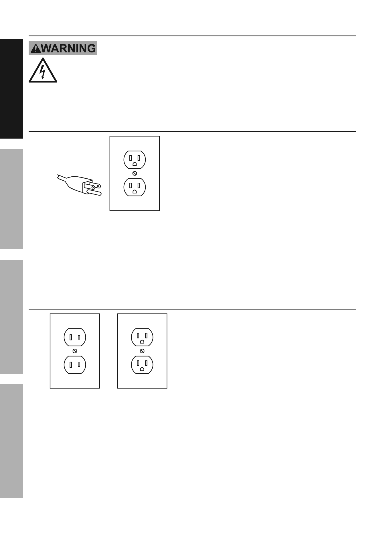
Grounded tools: tools with three prong plugs
3-prong plug and Outlet
1. Tools marked with “Grounding Required” have
a three wire cord and three prong grounding
plug. The plug must be connected to a properly
grounded outlet. If the tool should electrically
malfunction or break down, grounding provides
a low resistance path to carry electricity away
from the user, reducing the risk of electric shock.
(See 3-prong plug and Outlet.)
2. The grounding prong in the plug is connected
through the green wire inside the cord to the
grounding system in the tool. The green wire
in the cord must be the only wire connected to
the tool’s grounding system and must never
be attached to an electrically “live” terminal.
(See 3-prong plug and Outlet.)
3. The tool must be plugged into an appropriate outlet,
properly installed and grounded in accordance
with all codes and ordinances. The plug and outlet
should look like those in the preceding illustration.
(See 3-prong plug and Outlet.)
Double insulated tools: tools with two prong plugs
Outlets for 2-prong plug
1. Tools marked “Double Insulated” do not
require grounding. They have a special
double insulation system which satisfies
OSHA requirements and complies with
the applicable standards of Underwriters
Laboratories, Inc., the Canadian Standard
Association, and the National Electrical Code.
2. Double insulated tools may be used in either of the
120 volt outlets shown in the preceding illustration.
(See Outlets for 2-prong plug.)
Page 7For technical questions, please call 1-888-866-5797.Item 57179
SaFEtyOpEratiOnMaintEnancE SEtup
Extension cords
1. Grounded tools require a three wire extension cord.
Double Insulated tools can use either
a two or three wire extension cord.
2. As the distance from the supply outlet increases,
you must use a heavier gauge extension cord.
Using extension cords with inadequately sized wire
causes a serious drop in voltage, resulting in loss of
power and possible tool damage. (See table a.)
3. The smaller the gauge number of the wire, the
greater the capacity of the cord. For example,
a 14 gauge cord can carry a higher current
than a 16 gauge cord. (See table a.)
4. When using more than one extension cord
to make up the total length, make sure
each cord contains at least the minimum
wire size required. (See table a.)
5. If you are using one extension cord for more
than one tool, add the nameplate amperes
and use the sum to determine the required
minimum cord size. (See table a.)
6. If you are using an extension cord outdoors, make
sure it is marked with the suffix “W-A” (“W” in
Canada) to indicate it is acceptable for outdoor use.
7. Make sure the extension cord is properly wired
and in good electrical condition. Always replace
a damaged extension cord or have it repaired
by a qualified electrician before using it.
8. Protect the extension cords from sharp objects,
excessive heat, and damp or wet areas.
taBLE a: rEcOMMEnDED MiniMuM WirE
GauGE FOr EXtEnSiOn cOrDS* (120/240 VOLt)
naMEpLatE
aMpErES
(at full load)
EXtEnSiOn cOrD
LEnGtH
25´ 50´ 75´ 100´ 150´
0 – 2.0 18 18 18 18 16
2.1 – 3.4 18 18 18 16 14
3.5 – 5.0 18 18 16 14 12
5.1 – 7.0 18 16 14 12 12
7.1 – 12.0 18 14 12 10 -
12.1 – 16.0 14 12 10 - -
16.1 – 20.0 12 10 - - -
* Based on limiting the line voltage drop to five volts at
150% of the rated amperes.
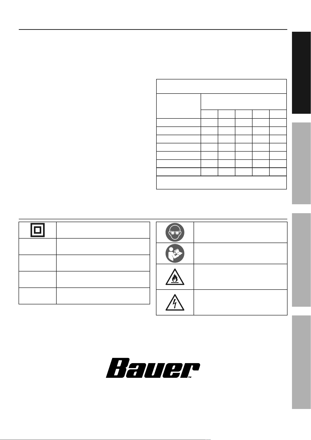
Symbology
Double Insulated
V
Volts
~
Alternating Current
a
Amperes
n
0
xxxx/min.
No Load Revolutions per Minute (RPM)
WARNING marking concerning Risk
of Eye Injury. Wear ANSI-approved
safety goggles with side shields.
Read the manual before
set-up and/or use.
WARNING marking
concerning Risk of Fire.
Do not cover ventilation ducts.
Keep flammable objects away.
WARNING marking concerning
Risk of Electric Shock.
Properly connect power cord
to appropriate outlet.
Page 8 For technical questions, please call 1-888-866-5797. Item 57179
SaFEty OpEratiOn MaintEnancESEtup
Specifications
Electrical Rating 120 VAC / 60 Hz / 15 A
Rated No Load Speed 4500 RPM
45° Cross Cut Capacity 3-1/2" x 9"
90° Cross Cut Capacity 3-1/2" x 12-1/2"
Maximum Bevel 48° Left and Right
Maximum Miter 52° Left – 60° Right
Saw Blade
10" Diameter,
5/8" Round Arbor
4500 Minimum RPM Rating
Setup - Before use:
read the EntirE iMpOrtant SaFEty inFOrMatiOn section at the beginning of this
manual including all text under subheadings therein before set up or use of this product.
note: For additional information regarding the parts listed in the
following pages, refer to Parts List and Diagram on page 22.
Mounting
1. Use the four bolt holes provided in the Base
to mount the Miter Saw to a stable support
before use. Mounting hardware not included.
2. Ensure that the Miter Saw is always stable
and secure (e.g. fixed to a bench).
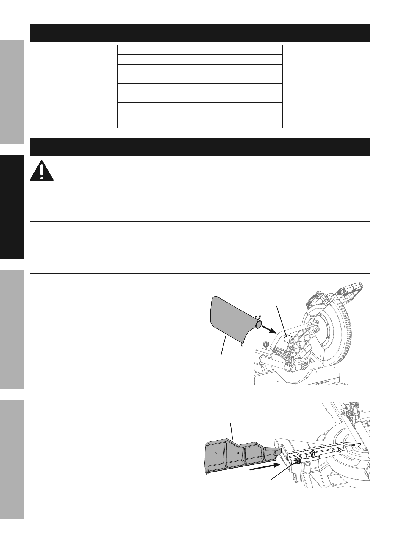
assembly
1. Slide the Dust Collection Bag over the Dust Outlet at
the rear of the Saw Head Assembly.
2. Install the Right Sliding Fence:
a. Loosen the Fence Lock Knob
counter-clockwise.
b. Insert the Right Sliding Fence into the slot
and slide the Fence to the desired position.
c. Tighten the Fence Lock Knob.
Dust
Bag
Dust
Outlet
Figure a
Fence
Lock Knob
right Sliding
Fence
Figure B
Page 9For technical questions, please call 1-888-866-5797.Item 57179
SaFEtyOpEratiOnMaintEnancE SEtup
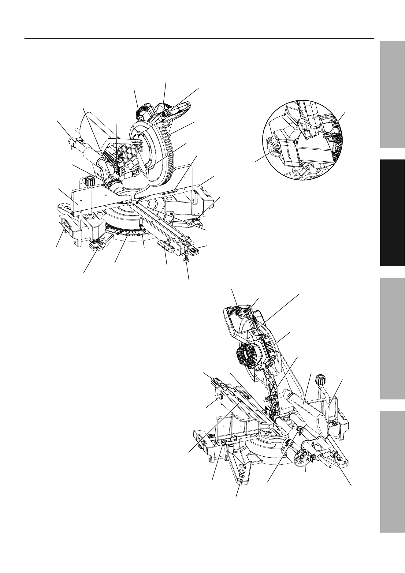
Functions
Motor
Trigger Lock
Button
Lower Blade
Guard
Saw Blade
Fence
Carrying Handle
Cut Stop
Base
Miter Scale
Miter Angle
Indicator
Bevel Lock
Handle
Leveling Foot
Miter Lock
Handle
Miter Table
Table
Table Extension
Lock Lever
Slide Bar
Lock-Down
Head
Pin
Bevel Scale
Bevel Angle
Indicator
Sliding Fence
Extension
Trigger
Upper Blade
Guard
Handle
Kerf Board
Dust Bag
Depth
Adjustment
Bolt
Mounting Hole
Miter Latch
Latch
Lever
Depth Stop
Detent
Button
Shadow Cut Line
Guide System
On/Off Switch
Bevel Angle
Lock Button
Slide Lock
Knob
Fence
Lock Knob
Wrench
Workpiece
Clamp
Brush Cap
Spindle
Carbon
Lock

Page 10 For technical questions, please call 1-888-866-5797. Item 57179
SaFEty OpEratiOn MaintEnancESEtup
Work area
1. Designate a work area that is clean and well lit.
The work area must not allow access by children
or pets to prevent distraction and injury.
2. There must not be objects, such as utility lines,
nearby that will present a hazard while working.
3. Route the power cord along a safe route to reach
the work area without creating a tripping hazard or
exposing the power cord to possible damage. The
power cord must reach the work area with enough
extra length to allow free movement while working.
Saw Blade Selection
1. Any saw blade that will be used must be
marked as suitable for the material to be cut.
2. Use only a saw blade diameter in
accordance with the markings on the saw.
See specification table for the bore diameter
and the maximum kerf of the saw blade.
3. Use only saw blades that are marked with a speed
equal or higher than the speed marked on the tool.
Guard Setup
Check that the Lower Blade Guard is in place,
moves freely, and closes instantly.
Dust Extraction Setup
1. To use the Dust Collection Bag, slide the Bag
over the Dust Outlet at the rear of the Saw Head
Assembly. Refer to Assembly on page 8.
2. The Dust Outlet also accepts a 1-1/2"
vacuum hose to use a dust collection
system instead of the Dust Bag.
Page 11For technical questions, please call 1-888-866-5797.Item 57179
SaFEtyOpEratiOnMaintEnancE SEtup
Operating instructions
read the EntirE iMpOrtant SaFEty inFOrMatiOn section at the beginning of this
manual including all text under subheadings therein before set up or use of this product.
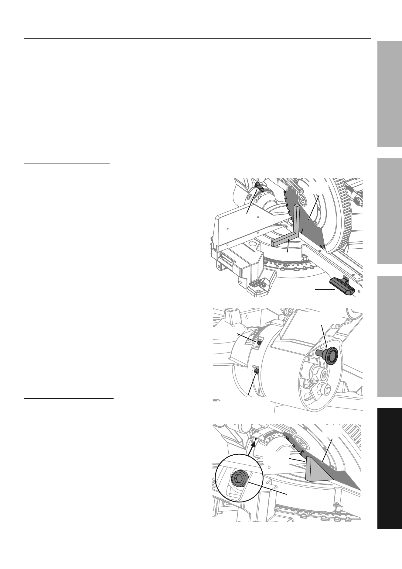
tool changing
note: Replacement blade sold separately.
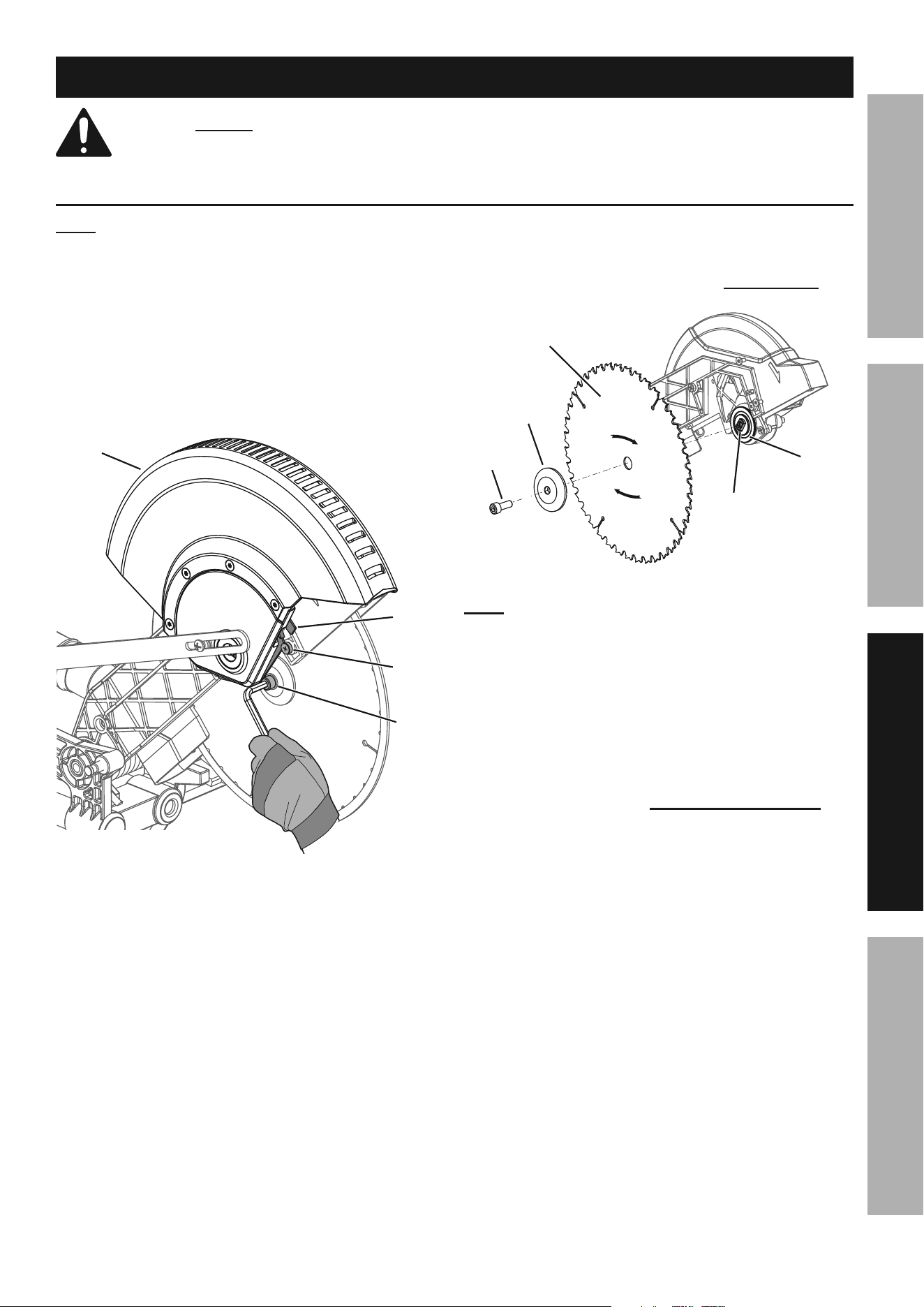
1. Unplug the tool from its power source.
2. Pull out the Head Lock-Down Pin, raise the Saw
Head to the upper position, then raise the Lower
Blade Guard out of the way and hold it up.
3. Loosen the Guard Plate Bolt until it
disengages the Guard Plate.
4. Swing the Guard Plate up and out of the way.
Lower
Blade
Guard
Guard
plate
Guard
plate
Bolt
arbor
Bolt
Figure c
5. Press in the Spindle Lock on the back
of the saw′s head and hold it in.
6. Remove the Arbor Bolt and Outer Flange.
Refer to Figure D.
iMpOrtant: the arbor Bolt has a left-handed
thread and removes by turning cLOcKWiSE.
Figure D
Outer
Flange
inner
Flange
Spindle
Blade
arbor
Bolt
note: Make sure the Inner Flange
stays in place on the Spindle.
7. Remove the used blade. Install the new Blade.
Make sure that the Blade′s rotation arrow
points in the same direction as the rotation
arrow on the upper Blade Guard.
8. Replace the Outer Flange and Arbor Bolt. Position
the cupped side of the Flange against the Blade.
Hold in the Spindle Lock and wrench tighten the
Arbor Bolt by turning it cOuntErcLOcKWiSE.
Release the Spindle Lock.
9. Rotate the Guard Plate back into place,
and secure it with the Guard Plate Bolt.
10. WarninG! tO prEVEnt SEriOuS inJury:
Make sure the Lower Blade Guard operates
smoothly and properly protects from
the Blade before using the Saw.
Page 12 For technical questions, please call 1-888-866-5797. Item 57179
SaFEty OpEratiOn MaintEnancESEtup
Setting and testing
tO prEVEnt SEriOuS inJury FrOM acciDEntaL OpEratiOn:
Make sure that the trigger is in the off-position and unplug the tool from its
electrical outlet before performing any procedure in this section.
adjusting the Miter angle
A miter cut is one that is at an angle across the
horizontal surface of the material. 45º miter
cuts to join two pieces in a right angle corner
are common. A 30º cut is often used for a
scarf joint or to make a chamfered end.
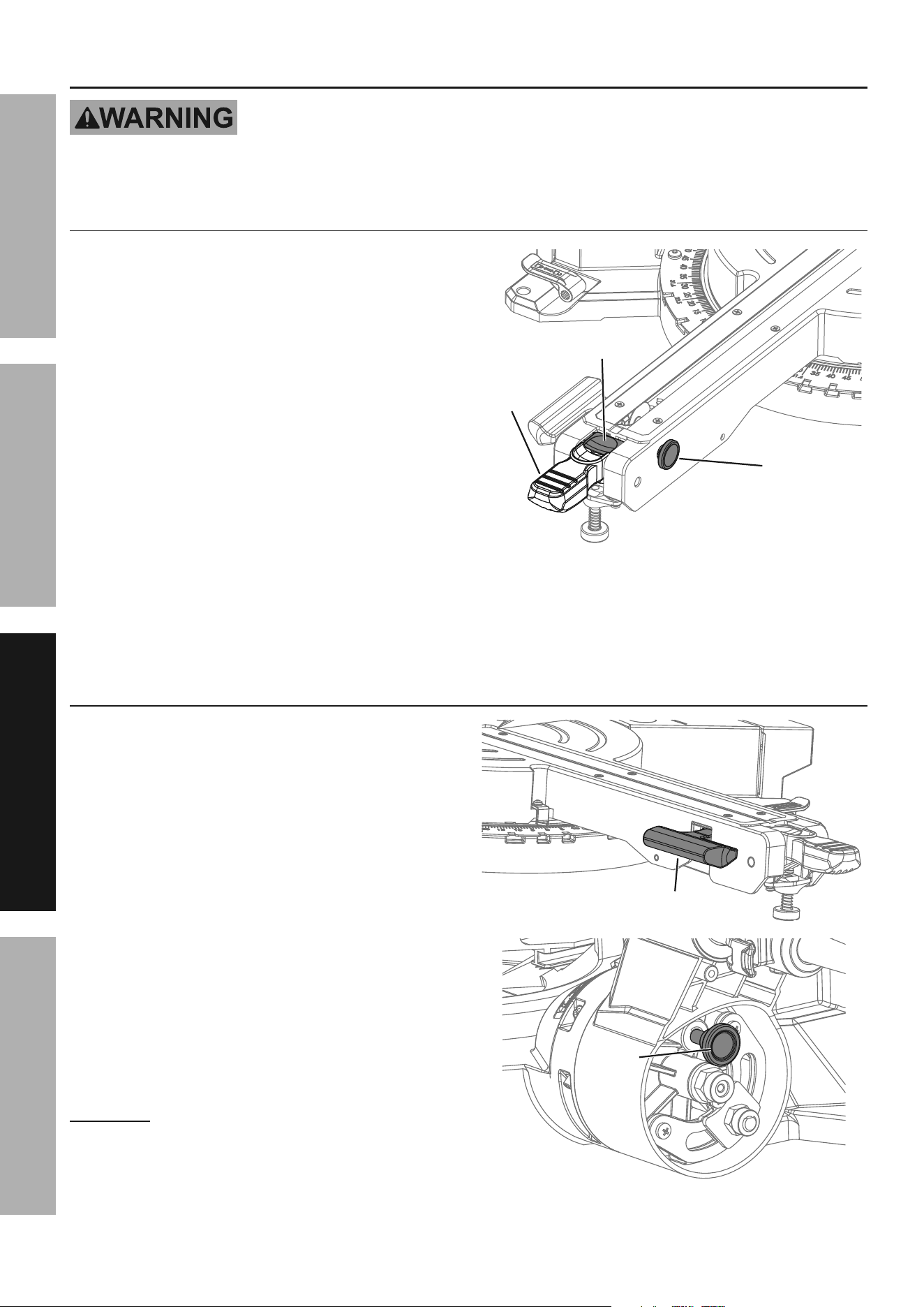
1. Pull up on the Miter Lock Handle to unlock the
Table. Push down on the Miter Latch Lever
and move the Table to the desired angle.
2. The Miter Angle Indicator will indicate the selected
angle. When the Miter Latch Lever is released,
the Table will lock into place at often used miter
angles, including 0º, 15º, 22.5º, 31.6º, and 45º
left and 0º, 15º, 22.5º, 31.6º, 45º, and 60º right.
3. To override the pre-set detents (stops) for micro
adjustments at any angle, push down and hold
the Miter Latch Lever and push in on the Detent
Latch Button to latch in place. Release the Miter
Latch Lever and adjust Table to any position on the
miter scale. To disengage push down on the Miter
Latch Lever to release the Detent Latch Button.
Miter Latch
Lever
Miter
Lock
Handle
Detent
Latch
Button
Figure E
4. Push down on the Miter Lock Handle to lock
the Table after adjusting the miter angle.
5. With the Table adjusted to the desired angle,
place the workpiece flush against the Fence,
secure it with the Clamp and make the cut.
adjusting the Bevel angle
A bevel cut is one that is at an angle vertically. Bevel
cuts can be used to miter relatively wide and thin
material. Bevel cuts can be used in combination with
a miter cut to form a compound angle. Compound
angle cuts are often used in crown moldings,
picture frames and similar trim materials.
1. Pull up on the Bevel Lock Handle to
unlock the Saw Head Assembly.
2. To adjust the left bevel angle, move the Saw Head
Assembly to the left to the desired angle. Read
the angle on the Bevel Scale. To adjust the right
bevel angle, pull out the Bevel Angle Lock Button
at the rear of the Saw and move the Saw Head
Assembly to the right to the desired angle.
3. Lock the Saw Head Assembly into position by
pushing down on the Bevel Lock Handle.
4. Make a sample cut in a piece of scrap to
confirm that the bevel angle is correct.
If it is not, correct the angle before cutting.
WarninG! tO prEVEnt SEriOuS inJury:
adjust both sides of the Fence clear of the Blade’s
cutting path after making any adjustment to the
cutting angle. Move the Blade through its full
range of motion to ensure the Fences are clear.
Bevel angle Bevel angle
Lock ButtonLock Button
Bevel Lock
Handle
Figure F
Page 13For technical questions, please call 1-888-866-5797.Item 57179
SaFEtyOpEratiOnMaintEnancE SEtup
aligning the Fence
1. After adjusting the miter, bevel, or depth setting,
check and adjust both sides of the Fence.
2. Loosen one of the Fence Lock Knobs, and move
its Sliding Fence to be within 1/8" of the blade.
3. Tighten the Fence Lock Knob. Make sure that the
Sliding Fence still does not contact the Blade.
4. Repeat the process for the other Fence
Lock Knob and Sliding Fence.
using the Depth Stop
If a kerfing or rabbet cut which does not cut
through the workpiece is desired, use the
Depth Stop to control the depth of the cut.
1. Pull out the Head Lock-Down Pin and
raise the Saw Head Assembly.
2. Rotate the Depth Stop down to a horizontal
position to use the Depth Adjustment Bolt setting.
3. Pull down on the Saw Head to
check the current setting.
4. To change the setting, first loosen the Lock
Nut on the Depth Adjustment Bolt. Turn the
Depth Adjustment Bolt clockwise to decrease
depth and counterclockwise to increase depth.
Tighten the Lock Nut after adjustment.
Depth Depth
adjustment adjustment
BoltBolt
Lock nut
Depth
Stop
Figure G
5. To disengage, rotate the Depth Stop
up to its vertical position.
Kerf Board Replacement / Adjustment
If the Kerf Boards become damaged
they must be replaced.
1. Remove the six screws holding the two Kerf
Boards in place and lift them from the Saw.
2. Install the new Kerf Boards, placing them
on either side of the cut line. Replace the
six screws and tighten them slightly.
to adjust the Kerf Boards:
1. Lower the Saw Head Assembly and lock it
down with the Head Lock-Down Pin.
2. Check for blade clearance by moving the Saw
Head through its full range of motion with the
bevel angle set at 0º, at maximum left bevel
angle, and at maximum right bevel angle. Refer
to Adjusting the Bevel Angle on page 12.
3. If the Saw Blade hits either of the Kerf
Boards, loosen the three screws for that
Board and adjust. Tighten the screws
and check again for blade clearance.
Kerf Kerf
BoardBoard
Kerf Kerf
BoardBoard
ScrewScrew
Figure H
4. After verifying blade clearance, tighten the six
screws holding the Kerf Boards in place.

Page 14 For technical questions, please call 1-888-866-5797. Item 57179
SaFEty OpEratiOn MaintEnancESEtup
Workpiece Set up
1. Secure loose workpieces using a vise or clamps
(not included) to prevent movement while working.
2. Cut only the following materials:
Dimensional lumber, plywood, particle board, plastic.
note: Use caution to avoid overheating the cutting tips.
If cutting plastic, cut at an even pace to avoid melting it.
3. Refer to cutting capacities in the Specifications Table
on page 8 for limitations on workpiece size.
4. Allow room on both left and right sides
of Saw for extended workpieces.
5. Use additional supports if needed to ensure
the stability of the workpiece. Mount the Saw
so that the surface is level to the ground, and
additional supports to provide a surface on the
same level as the saw table. If the work surface
and any workpiece supports are not level, and
on the same level, unwanted bevel angles will
appear in the cuts resulting in poor joinery.
6. Secure workpieces to the saw table using the Clamp
or other clamping devices (not included). Securing
the workpiece will provide safety by preventing kick
back and by removing the need to hold workpieces
near the blade by hand. Clamping the workpiece
will also improve cutting accuracy by preventing the
workpiece from moving during the cutting operation.
using the Workpiece Extension Supports
1. The Table Extensions are located on each
side of the Table, and locked in place using
the Table Extension Lock Levers.
2. When properly installed, the upper face of
the Table Extensions are level with the Table,
and provide a wider support surface for the
workpiece. Each Extension has a Cut Stop Lever
which can be raised to make repetitive cuts.
3. Support the workpiece to be level with the table,
and so that after the cut is made the cut off pieces
will not fall. Use sawhorses or other supports
(not included) to support longer workpieces.
4. If the workpiece is not level, you will make
an unintentional bevel cut in the material.
If the workpiece is not supported, it will bind
the blade and may cause the material to
kick back, potentially causing injury.
General instructions for use
1. Make sure that the Trigger is in the
off-position, then plug in the tool.
WarninG! tO prEVEnt SEriOuS inJury:
The tool will restart automatically if stalled.
Sliding Miter Saw cutting procedure
2. Unlock the Head Lock-Down Pin.
3. Check that all adjustment knobs are tight (Miter
Lock Handle, Bevel Lock Handle, Fence Lock
Knobs, and Table Extension Lock Levers).
4. Blow any sawdust or debris away from the Fence.
Place the work material against the Fence.
5. To use the Shadow Cut Line Guide System to
align the cut, turn its Switch on. Pull the Saw
Head down until the Saw Blade is close to the
workpiece and the Blade’s shadow appears on
the work material, indicating where the Blade
will cut. Align the marked location of the cut on the
workpiece with the edge of the Saw Blade shadow.
6. The Saw will also operate without using the
Shadow Cut Line Guide System if desired. In that
case align the marked location of the cut on the
work material with the saw blade. To prevent the
workpiece from being cut too short, align the edge
of the blade with the measured mark, keeping the
rest of the blade on the waste side of the cut.
7. Hold the work material in place using the Clamp.
Ensure that the work material is level and supported
securely. Use saw horses or supports if necessary.
DanGEr! Saws can quickly
amputate fingers if misused.
Keep hands well clear of cutting area.
8. Grip the Saw Handle, press the Trigger
Lock Button with your thumb, and
squeeze the Trigger to start the Saw.
9. Use two hands and hold workpiece securely
against table and fence at all times.
Page 15For technical questions, please call 1-888-866-5797.Item 57179
SaFEtyOpEratiOnMaintEnancE SEtup
10. With narrow material, press down lightly to
cut the workpiece. Press straight down,
“chopping” the material. Do not bear down on
the material — use light downward pressure.
If the material binds the blade, release the Trigger.
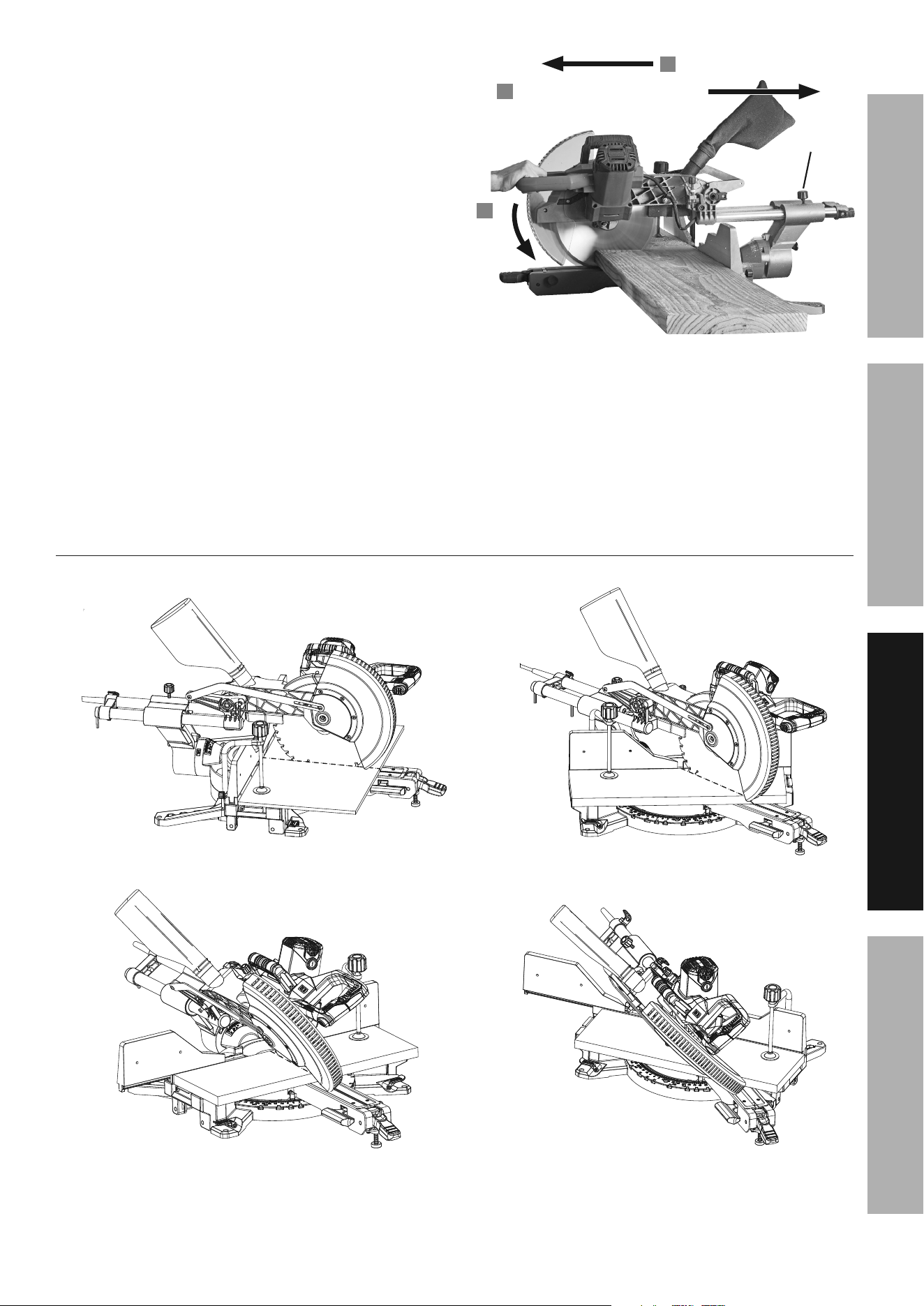
11. With wide material, move the Blade across
the workpiece while cutting as follows:
a. Loosen Slide Lock Knob and pull
Saw Head Assembly forward.
b. Press down on the Saw Handle.
c. Push the Saw Head toward the rear to
make the cut. Refer to Figure I.
Do not bear down on the material — use light
downward and lateral pressure. If the material
binds the blade, release the Trigger.
12. When the cut is completed, raise the Saw
Head, release the Trigger, wait for the Blade
to stop turning, release the Clamp and
remove the workpiece from the Saw.
13. To prevent accidents, turn off the tool and
unplug it after use. Clean, then store the
tool indoors out of children’s reach.
WorkpieceWorkpiece
pull Forward
1
press
Down
2
Slide Lock Slide Lock
KnobKnob
push toward rear to cut
3
Figure i
14. Lock the Saw Head down and lock all other
adjustments before moving the Saw. Use the
Carrying Handle and handle cut outs on each side of
the Base to lift and support the Saw while moving it.
cutting Operations
cross cut
Miter cut
Bevel cut
compound cut

Page 16 For technical questions, please call 1-888-866-5797. Item 57179
SaFEty OpEratiOn MaintEnancESEtup
Maintenance and Servicing instructions
procedures not specifically explained in this manual must
be performed only by a qualified technician.
tO prEVEnt SEriOuS inJury FrOM acciDEntaL OpEratiOn:
Make sure that the trigger is in the off-position and unplug the tool from its
electrical outlet before performing any procedure in this section.
tO prEVEnt SEriOuS inJury FrOM tOOL FaiLurE:
Do not use damaged equipment. if abnormal noise or vibration
occurs, have the problem corrected before further use.
cleaning, Maintenance, and Lubrication
1. BEFOrE EacH uSE, inspect the general
condition of the tool. Check for:
• loose hardware
• misalignment or binding of moving parts
• damaged cord/electrical wiring
• cracked or broken parts
• any other condition that may
affect its safe operation.
2. aFtEr uSE, wipe external surfaces of the tool with
clean cloth. Carefully clean the dust collection chute
and the area around the Lower Blade Guard. Check
that the Lower Blade Guard moves smoothly through
its entire range of movement, without sticking.
3. Periodically, wear ANSI-approved
safety goggles and NIOSH-approved
breathing protection and blow dust out of
the motor vents using dry compressed air.
4. WarninG! tO prEVEnt SEriOuS
inJury: if the plug or the supply cord of this
power tool is damaged, it must be replaced
only by a qualified service technician.
checking and calibrating the Fence
The Fence holds the workpiece in a fixed position
while the Table and/or the Saw Head Assembly
are adjusted in a miter or bevel angle.
To make accurate cuts, the Fence must be
perpendicular (at a 90º angle) to the Saw Blade.
1. Before beginning work, make a test cut on scrap
material with the Table set to the 0º miter position.
2. Check the cut with an accurate square.
You can also reverse the two pieces, hold
the cut ends together, and hold a good
straight edge along the side of the pieces.
3. If either test reveals that the cut is not a true 90º
angle, adjust the Fence before beginning work.
if Fence needs adjustment:
1. First unplug the tool.
2. Loosen the Slide Lock Knob and push
the Saw Head Assembly to its rearmost
position and retighten the Knob.
3. Lower the Saw Head Assembly and lock it
in place using the Head Lock-Down Pin.
4. Lay a carpenter’s square on the Table with
one edge along the Blade and the other along
the Fence. Any inaccuracy should be visible.
NOTE: The square must contact the surface of
the blade, not the teeth, for an accurate reading.
5. The Fence is held in place with four Fence Adjusting
Bolts. Remove both Sliding Fences to access the
Bolts. Loosen the Bolts slightly, and gently tap the
Fence into position using a soft mallet. Tighten
the Bolts and make another test cut. Repeat the
process until the Fence is adjusted accurately.
Fence Fence
adjusting adjusting
BoltsBolts
Page 17For technical questions, please call 1-888-866-5797.Item 57179
SaFEtyOpEratiOnMaintEnancE SEtup
calibrating the Bevel angle
For making accurate cuts, the Saw Blade must
be adjusted to be exactly vertical to the Table.
1. To check the angle, have the Saw Head
Assembly in its normal upright position and
set to the 0º bevel position. Make a cut on a
piece of flat sided, fairly thick scrap material.
2. Check the cut with an accurate square.
The cut should be at exactly 90º.
3. Angle can also be checked by rotating one cut-off
piece 180º and holding the cut ends together.
If the cut is not exactly vertical, the two
pieces will form a slight angle.
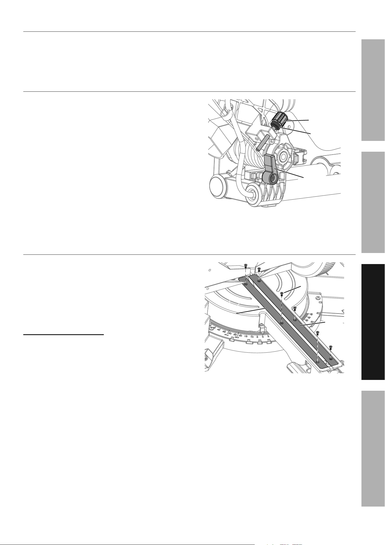
0° Bevel angle adjustment
1. First unplug the tool.
2. Set the Miter Table at 0°.
3. Unlock the Bevel Lock Handle, move the Saw Head
Assembly until the Bevel Angle Indicator is at 0° on
the Bevel Scale, then lock the Bevel Lock Handle.
4. Pull down the Saw Head until the
Blade just enters the table insert.
5. Place a framing square on the Miter Table
and up against the Saw Blade. NOTE: The
square must contact the surface of the Blade,
not the teeth, for an accurate reading.
6. If the Blade is not 90° square with the Miter
Table, loosen the 0° Bevel Set Bolt on the
saw arm with a hex key (not included).
7. Adjust the saw arm perpendicular to the Miter Table.
8. After alignment is achieved, tighten
the 0° Bevel Set Bolt.
WarninG! tO prEVEnt SEriOuS inJury:
Adjust both sides of the Fence clear of the Blade′s
cutting path after making any adjustment to the
cutting angle. Move the Blade through its full
range of motion to ensure the Fences are clear.
45° Bevel angle adjustment
Adjust the 45° bevel angle only after
performing the 0° bevel angle adjustment.
9. Remove the Sliding Fences.
10. Unlock the Bevel Lock Handle.
11. If required, pull out the Bevel Angle Lock Button to
enable the right bevel angle or bevel angle > 45°.
12. Move the Saw Head until the Bevel Angle
Indicator is at left 45° on the Bevel Scale.
13. Pull down the Saw Head until the
Blade just enters the table insert.
14. Place a triangle square on the Miter Table
and up against the Saw Blade.
15. If the Blade is not 45° with the Miter
Table, loosen the Left 45° Bevel Set Bolt
on the saw arm with a hex key.
16. Adjust the saw arm 45° to the Miter Table.
17. After alignment is achieved, tighten
the Left 45° Bevel Set Bolt.
18. Replace the Sliding Fences.
19. To adjust the right 45° bevel angle,
perform the same procedure described
above with the following excepttions:
• Move the Saw Head until the Bevel Angle
Indicator is at right 45° on the Bevel Scale.
• Use the Right 45° Bevel Set Bolt for alignment.
Bevel Bevel
angle angle
indicatorindicator
Saw Saw
BladeBlade
Bevel Lock
Handle
SquareSquare
Bevel angle Bevel angle
Lock ButtonLock Button
right 45right 45° ° Bevel Bevel
Set BoltSet Bolt
00°° Bevel Bevel
Set BoltSet Bolt
Left 45Left 45° °
Bevel Set BoltBevel Set Bolt
triangle triangle
SquareSquare
Saw Saw
BladeBlade

Page 18 For technical questions, please call 1-888-866-5797. Item 57179
SaFEty OpEratiOn MaintEnancESEtup
calibrating the Miter angle indicator
Check the accuracy of the Miter Angle Indicator
only after checking or adjusting the Fence to
confirm that it is at 90º to the Saw Blade.
1. Loosen the Adjustment Screw holding
the Miter Angle Indicator in place.
2. Rotate it until the pointer is exactly on 0º.
3. Retighten the Screw.
Miter Miter
angle angle
indicatorindicator
adjustment adjustment
ScrewScrew
Page 19For technical questions, please call 1-888-866-5797.Item 57179
SaFEtyOpEratiOnMaintEnancE SEtup
troubleshooting
problem possible causes Likely Solutions
Tool will not start. 1. Cord not connected.
2. No power at outlet.
3. Tool’s thermal reset breaker
tripped (if equipped).
4. Internal damage or wear.
(Carbon brushes or
Trigger, for example.)
1. Check that cord is plugged in.
2. Check power at outlet. If outlet is unpowered,
turn off tool and check circuit breaker.
If breaker is tripped, make sure circuit is right
capacity for tool and circuit has no other loads.
3. Turn off tool and allow to cool.
Press reset button on tool.
4. Have technician service tool.
Tool operates slowly. 1. Forcing tool to work too fast.
2. Extension cord too long or cord
diameter too small.
1. Allow tool to work at its own rate.
2. Eliminate use of extension cord. If an extension
cord is needed, use one with the proper diameter
for its length and load. See Extension Cords
in Grounding section on page 6.
Performance
decreases over time.
Carbon brushes worn or damaged. Have qualified technician replace brushes.
Excessive noise
or rattling.
Internal damage or wear. (Carbon
brushes or bearings, for example.)
Have technician service tool.
Overheating. 1. Forcing tool to work too fast.
2. Blocked motor housing vents.
3. Motor being strained by long or
small diameter extension cord.
1. Allow tool to work at its own rate.
2. Wear ANSI-approved safety goggles and
NIOSH-approved dust mask/respirator while
blowing dust out of motor using compressed air.
3. Eliminate use of extension cord. If an extension
cord is needed, use one with the proper diameter
for its length and load. See Extension Cords
in Grounding section on page 6.
Follow all safety precautions whenever diagnosing or servicing the tool.
Disconnect power supply before service.

Page 20 For technical questions, please call 1-888-866-5797. Item 57179
SaFEty OpEratiOn MaintEnancESEtup
pLEaSE rEaD tHE FOLLOWinG carEFuLLy
THE MANUFACTURER AND/OR DISTRIBUTOR HAS PROVIDED THE PARTS LIST AND ASSEMBLY DIAGRAM
IN THIS MANUAL AS A REFERENCE TOOL ONLY. NEITHER THE MANUFACTURER OR DISTRIBUTOR
MAKES ANY REPRESENTATION OR WARRANTY OF ANY KIND TO THE BUYER THAT HE OR SHE IS
QUALIFIED TO MAKE ANY REPAIRS TO THE PRODUCT, OR THAT HE OR SHE IS QUALIFIED TO REPLACE
ANY PARTS OF THE PRODUCT. IN FACT, THE MANUFACTURER AND/OR DISTRIBUTOR EXPRESSLY
STATES THAT ALL REPAIRS AND PARTS REPLACEMENTS SHOULD BE UNDERTAKEN BY CERTIFIED AND
LICENSED TECHNICIANS, AND NOT BY THE BUYER. THE BUYER ASSUMES ALL RISK AND LIABILITY
ARISING OUT OF HIS OR HER REPAIRS TO THE ORIGINAL PRODUCT OR REPLACEMENT PARTS
THERETO, OR ARISING OUT OF HIS OR HER INSTALLATION OF REPLACEMENT PARTS THERETO.

Page 21For technical questions, please call 1-888-866-5797.Item 57179
SaFEtyOpEratiOnMaintEnancE SEtup
record product’s Serial number Here:
note: if product has no serial number, record month and year of purchase instead.
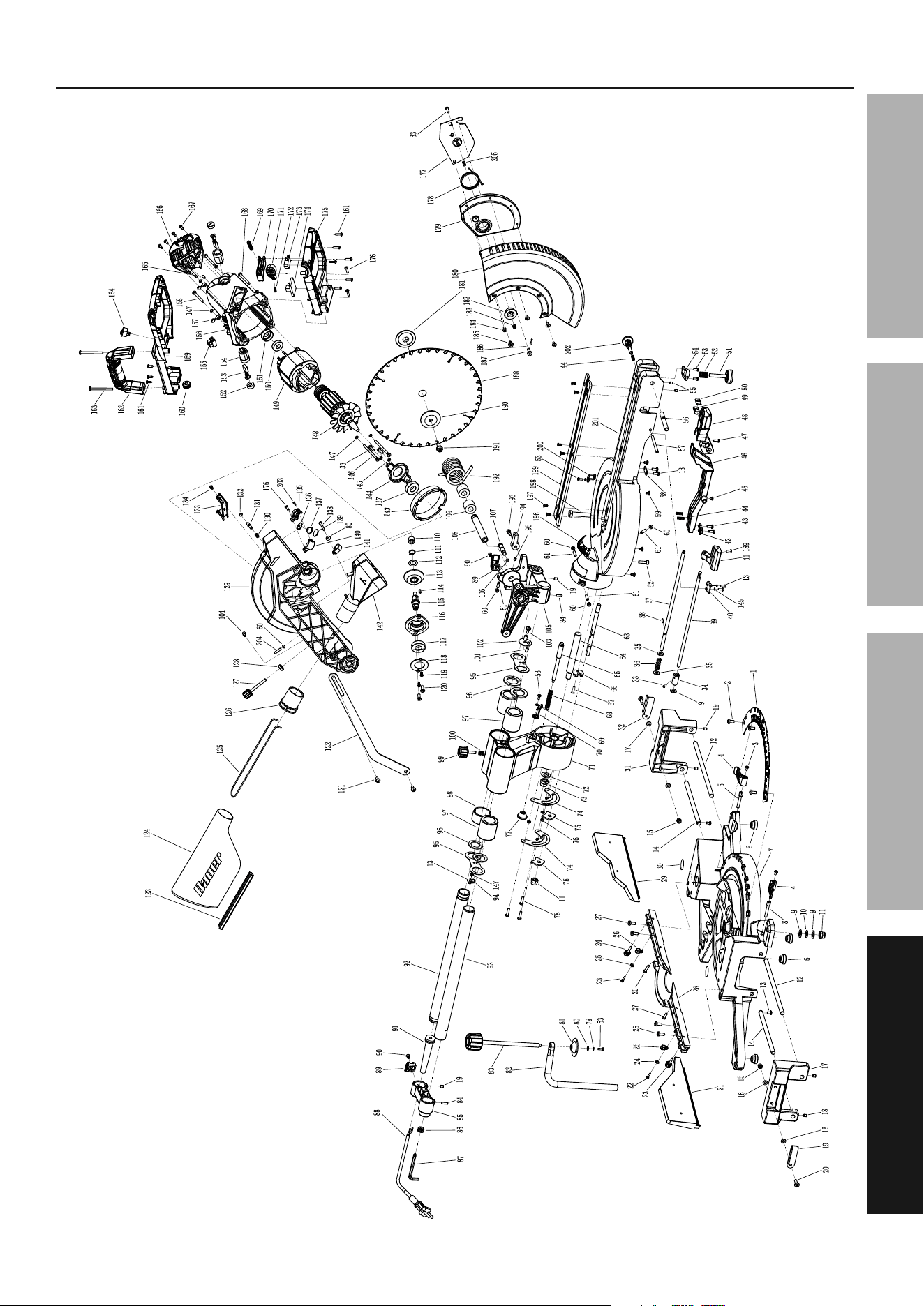
note: Some parts are listed and shown for illustration purposes only,
and are not available individually as replacement parts.

Page 22 For technical questions, please call 1-888-866-5797. Item 57179
SaFEty OpEratiOn MaintEnancESEtup
parts List and Diagram
parts List
part Description Qty
1 Miter Scale 1
2 Screw 3
3 Screw 2
4 Table Extension Lock Lever 2
5 Table Extension Bolt 1
6 Foot Pad 4
7 Base 1
8 Table Extension Bolt 1
9 Flat Washer 2
10 Elastic Washer 1
11 Locknut 2
12 Extension Rod Length 2
13 Screw 6
14 Short Extension Rod 2
15 Locknut 2
16 Flat Washer 4
17 Left Table Extension 1
18 Set Screw 7
19 Left Table Extension Cut Stop 2
20 Screw 3
21 Left Sliding Fence 1
22 Back Cover Screw 2
23 Lock Knob 2
24 Elastic Washer 2
25 Moving Limit Block 2
26 Bolt 4
27 Screw 1
28 Fence 1
29 Right Sliding Fence 1
30 Warning Label 1
31 Right Table Extension 1
32
Right Table Extension Cut Stop
1
33 Screw 5
34 Locking Sleeve 1
35 Large Flat Pad 1
36 Locking Handle Return Spring 3
37 Work Table Locking Ejector 1
38 Elastic Cylindrical Pin 1
39 Locking Lever 1
40 Locking Rod Pressure Plate 1
41 Bevel Lock Handle 1
42 Angle Positioning Block 1
43 Tapping Screw 2
44 Spring 3
45 Tapping Screws 1
46 Workbench Positioning Board 1
47 Tapping Screw 1
48 Work Table Locking Handle 1
49 Rotating Adjustment Pin 1
50 Block 1
51 Leveling Foot 1
52 Adjustment Screw Spring 1
53 Screw 5
54 Workbench Auxiliary Support 1
55 Flat End Set Screw 2
56 Locking Handle Shaft 1
57 Positioning Plate Axis 1
58 Press Plate 1
59 Friction Pad 6
60 Ring 7
61 Set Screw 4
62 Cap Screw 1
63 Arm Locking Shaft 1
64 Connecting Shaft 1
65 Head Angle Positioning Pin 1
66 Rotating Limit Plate 1
67 Screw 1
68 Spring 1
69 Flat Washer 2
part Description Qty
70 Bevel Angle Indicator 1
71 Arm 1
72 Flat Washer 1
73 Locknut 1
74 Locking Friction Pad 2
75 Locking Pad 2
76 Spacer 3
77 Bevel Angle Lock Button 1
78 Screw 3
79 Spring Washer 1
80 Large Flat Pad 2
81 Clamp Plate 1
82 Clamp Rod 1
83 Clamp Knob 1
84 Elastic Cylindrical Pin 2
85 Connection Sleeve 1
86 Wrench Storage Ring 1
87 Hex Key 1
88 Power Cord 1
89 Power Cord Clamp 2
90 Screw 3
91 Anti-Bending Sleeve 1
92 Right Sliding Bar 1
93 Left Sliding Bar 1
94 Cushion 1
95 Bearing Baffle 2
96 Wool Felt 4
97 Linear Bearing 3
98 Bearing Spacer 2
99 Slide Lock Knob 1
100 Slide Lock Knob Spring 1
101 Pin 1
102 Limit Plate Assembly 1
103 Limit Plate Screw 1
104 Head Limit Screw 1
105 Upper Blade Guard Bracket 1
106 O-Ring 1
107 Lock Pin 1
108 Head Shaft 1
109 Torsion Spring Bushing 2
110 Oil Bearing 1
111 Shaft Retaining Ring 1
112 Gear Axial Washer 1
113 Bevel Gear 1
114 C-Type Shaft Key 1
115 Output Shaft 1
116 Gear Cover 1
117 Bearing 2
118 Bearing Plate 1
119 Screw 2
120 Screw 2
121 Baffle Screw 2
122 Link 1
123 Dust Bag Sealing Bar 1
124 Dust Bag 1
125 Dust Bag Bracket 1
126 Dust Port 1
127 Depth Adjustment Knob 1
128 Knurled Nut 1
129 Upper Blade Guard 1
130 Gear Lock Spring 1
131 Gear Lock Pin 1
132 Circlip 1
133 Wire Plate 1
134 Screw 1
135 Right Lamp Holder 1
136 LED Light 1
137 LED Cover 1
138 Tapping Screw 1
part Description Qty
139 LED Lens 1
140 Left Lamp Holder 1
141 Clip 1
142 Dust Collection Chute 1
143 Windshield 1
144 Motor Shaft Pressure Plate 1
145 Spring Washer 2
146 Screw 2
147 Flat Washer 6
148 Armature Assembly 1
149 Stator Assembly 1
150 Bearing 1
151 Damping Ring 1
152 Nut 2
153 Carbon Brush 2
154 Brush Holder Assembly 2
155 Terminal 1
156 Motor Housing 1
157 Screw Cap 2
158 Screw 2
159 Upper Handle 1
160 Protective Coil 1
161 Tapping Screw 9
162 Carrying Handle 1
163 Screw 2
164 LED Switch 1
165 Hex Socket Set Screw 2
166 End Cover 1
167 Tapping Screw 4
168 Screw 2
169 Switch Button Spring 2
170 Trigger 1
171 Trigger Lock Button 1
172 Spring 1
173 Main Switch 1
174 Transformer 1
175 Lower Handle 1
176 Tapping Screw 3
177 Guard Plate 1
178 Torsion Spring 1
179 Shield Support Plate 1
180 Lower Blade Guard 1
181 Inner Flange 1
182 Guard Plate Sleeve 1
183 Locknut 1
184 Guard Connecting Screw 4
185 Guard Plate Screw 1
186 Spring Pin 1
187 Screw 1
188 Saw Blade 1
189 Screw 1
190 Outer Flange 1
191 Flange Bolt 1
192 Torsion Spring 1
193 Depth Stop Screw 1
194 Depth Stop 1
195 Set Screw 1
196 Bevel Scale 1
197 Countersunk Head Screw 6
198 Hex Head Bolt 1
199 Kerf Board 2
200 Miter Angle Indicator 1
201 Worktable 1
202 Lock Pin 1
203 Self-Tapping Screw 3
204 Set Screw 1
205 Shield Cushion 1
Page 23For technical questions, please call 1-888-866-5797.Item 57179
SaFEtyOpEratiOnMaintEnancE SEtup
assembly Diagram

26541 agoura road • calabasas, ca 91302 • 1-888-866-5797
Limited 90 Day Warranty
Harbor Freight Tools Co. makes every effort to assure that its products meet high quality and durability standards,
and warrants to the original purchaser that this product is free from defects in materials and workmanship for the
period of 90 days from the date of purchase. This warranty does not apply to damage due directly or indirectly,
to misuse, abuse, negligence or accidents, repairs or alterations outside our facilities, criminal activity, improper
installation, normal wear and tear, or to lack of maintenance. We shall in no event be liable for death, injuries
to persons or property, or for incidental, contingent, special or consequential damages arising from the use of
our product. Some states do not allow the exclusion or limitation of incidental or consequential damages, so the
above limitation of exclusion may not apply to you. THIS WARRANTY IS EXPRESSLY IN LIEU OF ALL OTHER
WARRANTIES, EXPRESS OR IMPLIED, INCLUDING THE WARRANTIES OF MERCHANTABILITY AND FITNESS.
To take advantage of this warranty, the product or part must be returned to us with transportation charges
prepaid. Proof of purchase date and an explanation of the complaint must accompany the merchandise.
If our inspection verifies the defect, we will either repair or replace the product at our election or we may
elect to refund the purchase price if we cannot readily and quickly provide you with a replacement. We will
return repaired products at our expense, but if we determine there is no defect, or that the defect resulted
from causes not within the scope of our warranty, then you must bear the cost of returning the product.
This warranty gives you specific legal rights and you may also have other rights which vary from state to state.