

Serial Number
SG24765
Purchase Date
ITEM #5974766
MODEL #KLMR 4252B-03
42 IN MAX-LITHIUM
RIDING LAWN MOWER
Español
p. 67
ATTACH YOUR RECEIPT HERE
Thank you for purchasing this KOBALT product.
Questions, problems or missing parts?
Before returning, contact us on: 888-3KOBALT (888-356-2258), 8 a.m.- 8 p.m.,
EST, Monday - Sunday or [email protected].
KOBALT and logo design are trademarks or
registered trademarks of LF, LLC. All rights
reserved.

2
TABLE OF CONTENTS
Package Contents ................................................................3
Hardware Contents . . . . . . . . . . . . . . . . . . . . . . . . . . . . . . . . . . . . . . . . . . . . . . . . . . . . . . . . . . . . . . . 7
Safety Information ...............................................................8
Preparation .................................................................... 15
Assembly Instructions . . . . . . . . . . . . . . . . . . . . . . . . . . . . . . . . . . . . . . . . . . . . . . . . . . . . . . . . . . . . 17
Operating Instructions ............................................................23
Care and Maintenance ...........................................................40
Troubleshooting ................................................................. 52
Warranty ......................................................................65
PRODUCT SPECIFICATIONS
COMPONENT SPECIFICATIONS
Voltage 52 V
Deck Size 42 in.
Wheel Size
Front 15 x 6 - 6 in.
Rear 20 x 10 - 8 in.
"Cold" Tire Pressure
Front 14 PSI (96.5 kPa)
Rear 10 PSI (68.9 kPa)
Blade Speed up to 3000 RPM
Maximum Driving Speed
Forward up to 5.5 MPH (8.8 km/h)
Reverse up to 2.7 MPH (4.4 km/h)
Cutting-Height Adjustment (12 positions) 1.5 – 4.5 in. (38.1 – 114.3 mm)
Maximum Towing Weight (total rolling weight) 600 lbs. (272 kg)
Ingress Protection (IP) Rating IPX4 (Protection from splashing water)
Recommended Charging Temperature 41 °F – 104 °F (5 °C – 40 °C)
Recommended Operating Temperature 32 °F – 104 °F (0 °C – 40 °C)
Recommended Storage Temperature -4 °F – 158 °F (-20 °C – 70 °C)
Weight 419 lbs. (190 kg)
3
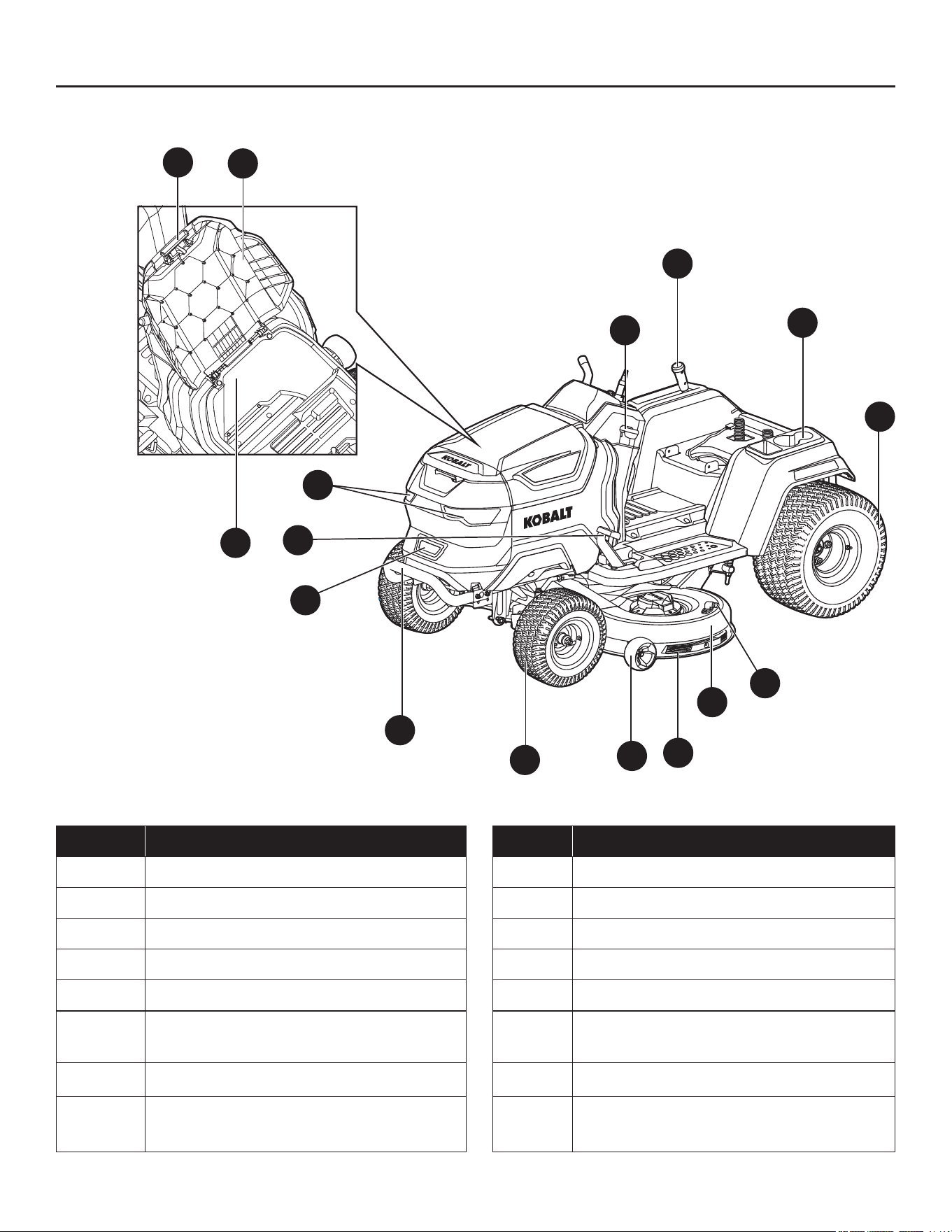
PACKAGE CONTENTS
L
O
P
N
M
A
B
C
E
F
G
H
I
D
J
K
PART DESCRIPTION PART DESCRIPTION
A Deck-height adjustment lever I Front bumper
B Cup holders & Storage space J Charging port
C Rear wheel (Drive wheel) (x2) K Parking-brake pedal
D Wash port L LED headlight (x2)
E Deck M Parking-brake lock lever
F Deck protector N
Storage compartment cover release
button
G Anti-scalp wheel (x2) O Storage compartment cover
H Front wheel (x2) P
Storage compartment- maximum
capacity: 66 lbs. (30 kg)

4
PACKAGE CONTENTS
U
T
S
Q
R
V
Y
W
X
PART DESCRIPTION PART DESCRIPTION
Q Accelerator pedal V Steering wheel
R Side discharge chute W Dust cover
S Hitch X Seat
T Storage box Y Seat position adjustment lever
U USB-A port
5
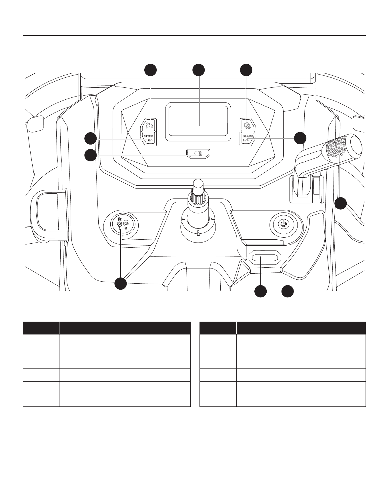
PACKAGE CONTENTS
I1
J1
G1
F1 E1
D1
A1 B1
C1
H1
PART DESCRIPTION PART DESCRIPTION
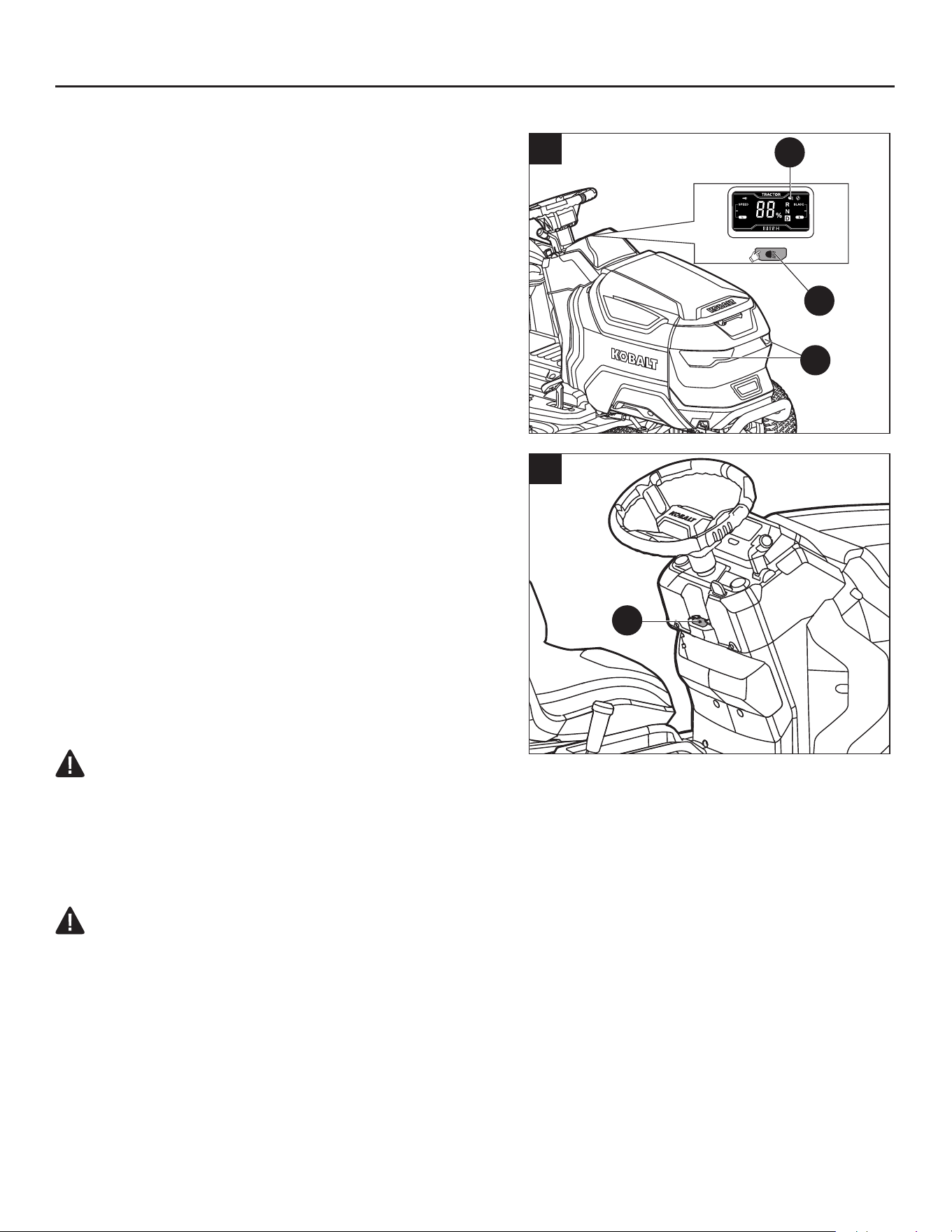
A1 LCD screen F1
Safety key slot (Safety key stored in
tool bag)
B1 Mowing in reverse button G1 Blade on/off button
C1 Blade speed adjustment button H1 LED headlights button
D1 Direction control lever I1 Driving speed adjustment button
E1 Start/Stop button J1 Cruise control button (CCS)
6
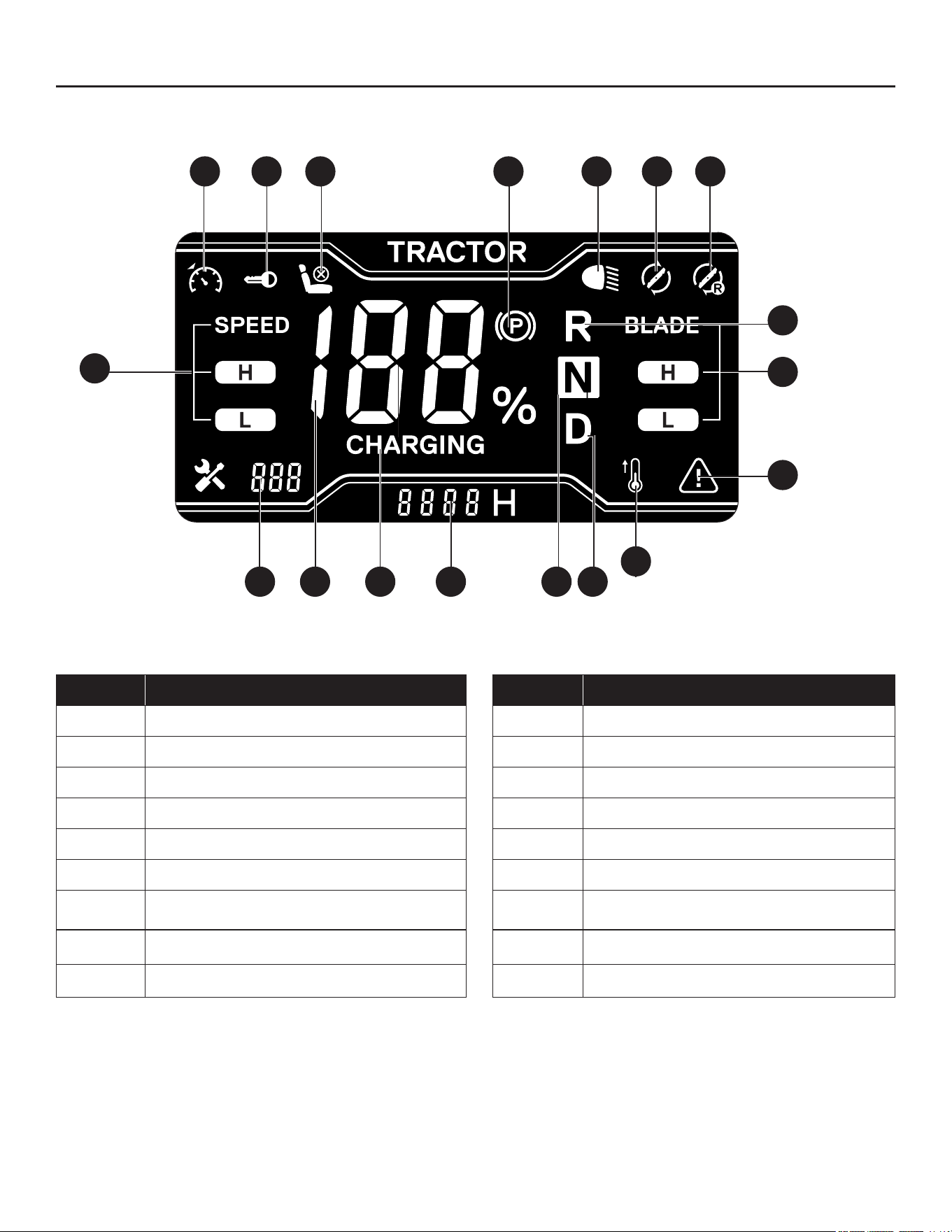
PACKAGE CONTENTS
s
a b c d e f g
k
h
i
nmopqr
PART DESCRIPTION PART DESCRIPTION
a Cruise control icon (CCS) j Temperature icon
b Safety key icon k Reverse direction indicator
c Seat sensor icon m Neutral direction indicator
d Parking-brake icon n Forward direction indicator
e LED headlights icon o Hour meter
f "Blade on" icon p "CHARGING" icon
g "Mowing in reverse" icon q Fuel gauge
h Blade speed indicator r Fault code indicator
i Alert icon s Driving speed indicator
NOTE: The text “TRACTOR” on the LCD screen is equivalent to the product name “MOWER”.
NOTE: Refer to the section “ICONS AND FAULT CODES ON LCD SCREEN” for more information
about the icons and indicators on the LCD screen.
j

7
PACKAGE CONTENTS
WARNING:
• Remove the machine from the package and examine it carefully. Do not discard the carton or any
packaging material until all parts have been examined.
• If any part of the machine is missing or damaged, do not use the machine until the part has been
repaired or replaced. Failure to heed this warning could result in serious injury.
HARDWARE CONTENTS (NOT TO SCALE)
M12 Nut
Qty. 1
Washer
Qty. 1
Step Bolt
Qty. 2
M8 Nut
Qty. 2
Safety Key
Qty. 2
Wash-port
Quick Coupler
Qty. 1
18 mm Socket
Wrench
Qty. 1
Combination
Wrench
Qty. 2
13 15
AA
EE FF GG HH
BB CC DD

8
SAFETY INFORMATION
Please read and understand this entire manual before attempting to assemble and operate the
product.
WARNING:
• The operation of any power tool can result in foreign objects being thrown into your eyes, which can
result in severe eye damage. Before beginning power-tool operation, always wear safety goggles
or safety glasses with side shields and a full-face shield, when needed. We recommend using a
wide vision safety mask over eyeglasses or standard safety glasses with shields. Always use eye
protection marked to comply with ANSI Z87.1.
9
SAFETY INFORMATION
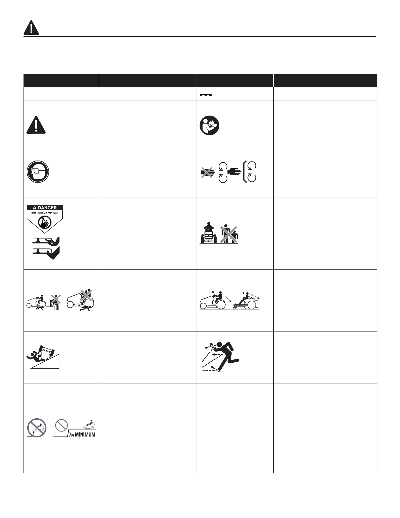
Some of the following symbols may be used on this machine. Please study them and their meaning.
Proper interpretation of these symbols will allow you to operate the machine better and more safely.
SYMBOL DEFINITION SYMBOL DEFINITION
V Volts
or d.c. Direct Current
A danger, warning,
or caution. It means
‘Attention! Your safety is
involved.’
To reduce the risk of injury,
user must read instruction
manual.
Always wear safety goggles
or safety glasses with side
shields and a full face shield
when operating this product.
Do not open or remove
safety shields while the
product is running.
To reduce the risk of injury,
keep hands and feet away
from rotating parts. Do not
operate unless discharge
cover or grass bag is in its
proper place. If damaged,
replace immediately.
Do not mow when children
or others are around.
Never carry children or
anyone, even when the
blades are off.
Always look down and
behind you before and when
maneuvering in reverse or
turning around. Make sure
children, bystanders, and
pets are clear of the area.
Use extra caution on
slopes. Do not mow slopes
greater than 15 degrees.
Do not use on slopes near
open water.
Remove objects that can
be thrown by the blade in
any direction. Wear safety
glasses.
Stay at least two mowing
widths (7 ft /2.13 m) away
from any ditches, drop-
offs, or water to avoid
accident going over the
edge or into the water.

10
SAFETY INFORMATION
SAFETY INSTRUCTIONS FOR LAWN MOWER
DANGER:
• This machine is capable of amputating hands and feet and throwing objects. Failure to observe the
following safety instructions could result in serious injury or death.
WARNING:
• Do not expose the mower to re or excessive temperature. Exposure to re or temperature above
265°F (130°C) may cause explosion.
General Information
• Read, understand, and follow instructions and warnings in this manual and on the machine and
attachments.
• Only allow persons who are responsible, trained, familiar with the instructions, and physically
capable to operate the machine.
• Do not carry passengers and keep bystanders away.
• Do not operate the machine while under the inuence of alcohol or drugs.
• Follow the manufacturer’s recommendation for wheel weights or counterweights.
Preparation before Operating
• Clear the operating area of any objects which could be thrown by or interfere with operation of the
machine.
• Keep the area of operation clear of all bystanders, particularly small children. Stop the machine and
attachment(s) if anyone enters the area.
• Do not operate the machine without the entire grass catcher, discharge chute, or other safety
devices in place and functioning properly. Check frequently for signs of wear or deterioration and
replace as needed.
• Wear appropriate personal protective equipment such as safety glasses, hearing protection, and
footwear.
Operation
• Only operate the machine in daylight or good articial light.
• Avoid holes, ruts, bumps, rocks, or other hidden hazards. Uneven terrain could overturn the
machine, or cause operator to lose their balance or footing.
• Do not put hands or feet near rotating parts or under the machine. Keep clear of the discharge
opening at all times.
• Do not direct discharge material toward anyone. Avoid discharging material against a wall or
obstruction. Material may ricochet back toward the operator. Stop the blade(s) when crossing gravel
surfaces.
• Do not leave a running machine unattended. Always park on level ground, disengage the
attachment, set parking brake, and stop the motor.

11
SAFETY INFORMATION
• Do not mow in reverse unless absolutely necessary. Always look down and behind before and while
backing.
• Avoid mowing wet grass. Mowing on wet surfaces can cause loss of control and the wheels to sink
into the soft lawn.
• If situations occur that are not covered in this manual, use care and good judgment. Contact Kobalt
customer service for assistance.
Children Specic
• Tragic accidents can occur if the operator is not alert to the presence of children. Children are often
attracted to the machine and the mowing activity. Never assume that children will remain where you
last saw them.
• Keep children out of the operating area and under the watchful care of a responsible adult other
than the operator.
• Do not carry children, even with the blade(s) shut off. Children could fall off and be seriously injured or
interfere with safe machine operation. Children who have been given rides in the past could suddenly
appear in the mowing area for another ride and be run over or backed over by the machine.
Slope Specic
WARNING: Slopes are a major factor related to accidents. Operation on slopes requires extra
caution.
• Travel in the manufacturer recommended direction on slopes. Use caution while operating near
drop-offs.
• Do not operate machine under any condition where traction, steering, or stability is in question. Tires
could slide even if the wheels are stopped.
• Always keep the machine in gear when going down slopes. Do not coast downhill.
• Avoid starting and stopping on slopes. Avoid making sudden changes in speed or direction. Make
turns slowly and gradually.
• Use extra care while operating machine with a grass catcher or other attachment(s). They can affect
the stability of the machine.
Hauling
• Use proper width ramps for loading and unloading a machine for transport.
Transport
• The machine is heavy and can cause serious crushing injuries. Be extra cautious when it is loaded
on or unloaded from a vehicle or trailer.
• Use proper width ramps for loading machine into a trailer or truck.
• Use an approved trailer to transport the machine. Engage the electric park brake by releasing the
accelerator pedal and with the parking-brake lock lever pulled up, fully depress the parking-brake
pedal to engage the parking brake. Fasten the machine down with approved devices such as
bands, chains, or straps.

12
SAFETY INFORMATION
• Both front and rear tie down straps must be used and directed down and out from the machine.
DANGER:
Use extreme caution when loading the machine into a truck or trailer using ramps.
There is the possibility of serious injury or death if the machine falls off the ramps.
WARNING: The parking-brake is not sufficient to lock the machine in place during transport.
Ensure that the machine is well fastened to the transport vehicle. Always reverse the machine onto
the transport vehicle to avoid tipping it over.
• Do not operate this machine on public roadways.
• Check and abide by local trafc regulations before transporting the machine on roads.
• Do not tow this machine, it may cause damage to the drive system.
• To reduce the risk of injury and property damage, NEVER drive the machine up or down the ramp.
Do not lift! The machine is not intended to be lifted by hand.
• When loading or unloading this machine, do not use more than the maximum recommended
operation angle of 15 degrees.
Towing
• Do not tow a cart that exceeds 600 lbs. (272 kg) total rolling weight. The weight of the cart and
other specications are included in the owner’s manual supplied with your cart.
• Attach towed cart only to the hitch. Risk of personal injury or property damage.
• Never allow children or other persons in or on towed cart. Risk of personal injury.
• Do not tow on inclines. The weight of the towed cart may cause loss of traction, loss of control
and the ability to stop when towing on inclined surface.
• Always use extra caution when towing with your mower. Make wide turns to avoid jack-kning.
Use care when reversing.
• Drive at slow speed and allow extra distance to stop.
• Do not tow near ditches, canals, and other hazards. There is a risk of loss of traction or control.
• Follow all the warnings and instructions provided by the cart manufacturer. Failure to follow
all instructions may result in personal injury or property damage.
• Follow the manufacturer’s recommendation for weight limits for towed equipment and
towing on slopes.
Service
WARNING: Grass bag components, the side discharge chute, and mulching plug are subject to
wear and damage, which could expose moving parts or allow objects to be thrown and could increase
the risk of injury. For safety protection, frequently check all components and replace damaged
components immediately with identical replacement parts, listed in this manual.
• Keep machine in good working order. Replace worn or damaged parts. Periodically check the motor
and brakes.
• Use caution when servicing blades. Wrap the blade(s) or wear gloves. Replace damaged blades.
Do not repair or alter blade(s).
• Always stop the motor and remove the safety key before servicing, cleaning, or removing material
from the lawn mower.

13
SAFETY INFORMATION
• After striking a foreign object, stop the motor, remove the safety key, allow the blade(s) to stop
rotating, and thoroughly inspect the lawn mower for any damage. Repair the damage before
operating the lawn mower.
• Have your lawn mower serviced by a qualied repair person using only identical replacement parts.
This will ensure that the safety of the lawn mower is maintained.
• Follow instructions for changing accessories.
• Keep the lawn mower free from accumulation of grease, dirt, and other possibly combustible materials.
• Keep all nuts, bolts, and screws tight to be sure the lawn mower is in safe working condition.
• Never remove or tamper with safety devices. Regularly check their proper operation. Never do
anything to interfere with the intended function of a safety device or to reduce the protection
provided by the safety device.
• Maintain or replace safety and instruction labels, as necessary.
• Recharge only with the charger specied by the manufacturer. A charger that is suitable for one type
of battery pack may create a risk of re when used with another battery pack.
• Do not charge lawn mower in rain, or in wet locations.
• Do not use battery-operated lawn mower in rain.
• Do not wash the lawn mower with a hose; avoid getting water in the motor and electrical connections.
• Store idle lawn mower indoors - When not in use, lawn mower should be stored in an indoor, dry,
and locked-up place and out of reach of children.
Additional Warnings
• The battery pack is integrated with the product and should not be removed from the product.
• Use only with the KOBALT battery charger KRC 752-03.
• The charger manual is provided separately and includes specic safety rules and operating
instructions. Please refer to the charger manual for safety rules and detailed operating instructions.
FCC Statement
a This device complies with Part 15 of the FCC Rules. Operation is subject to the following two conditions:
a) This device may not cause harmful interference.
b) This device must accept any interference received, including interference that may cause
undesired operation.
b Changes or modications not expressly approved by the party responsible for compliance could
void the user's authority to operate the equipment.
NOTICE: This equipment has been tested and found to comply with the limits for a Class B digital
device, pursuant to Part 15 of the FCC Rules. These limits are designed to provide reasonable
protection against harmful interference in a residential installation. This equipment generates,
uses, and can radiate radio frequency energy and, if not installed and used in accordance with
the instructions, may cause harmful interference to radio communications. However, there is no
guarantee that interference will not occur in a particular installation. If this equipment does cause
harmful interference to radio or television reception, which can be determined by turning the
equipment off and on, the user is encouraged to try to correct the interference by one or more of the
following measures: Reorient or relocate the receiving antenna. Increase the separation between the
equipment and receiver. Connect the equipment into an outlet on a circuit different from that to which
the receiver is connected. Consult the dealer or an experienced radio/TV technician for help.

14
PREPARATION
Know Your Lawn Mower
Your mower has been designed for the purposes listed below:
• Mowing your lawn
Before beginning assembly of product, make sure all parts are present. Compare parts with package
contents list and hardware contents list. If any part is missing or damaged, do not attempt to assemble
the product.
Tools Required for Unpacking:
• Scissors or side cutters (not supplied)
• Two combination wrenches (supplied)
Tools Required for Assembly and Adjustment:
• Two combination wrenches (supplied)
• One 18 mm socket wrench (supplied)
WARNING:
• Do not allow familiarity with the mower to cause carelessness. Remember that one careless
moment is enough to cause severe injury.
• Before attempting to use any machine, be sure to become familiar with all of the operating features
and safety instructions.
• Do not attempt to modify this machine or create accessories not recommended for use with this
machine. Any such alteration or modication is misuse and could result in a hazardous condition
leading to possible serious personal injury.
1. Unpacking
WARNING:
• To reduce the risk of injury or mower damage, do not use a knife to cut the nylon straps. Use
scissors or side cutters.
WARNING:
• To reduce the risk of damage, remove watches or other fragile and valuable items from your wrists.
There’s a risk of accidental contact with steel frame elements.
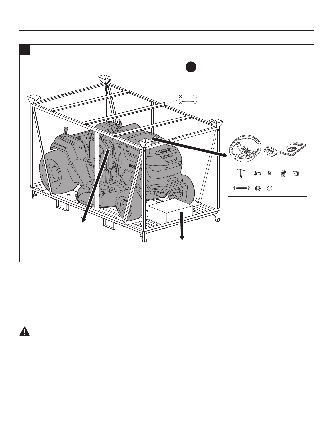
a. Remove the plastic cover from the frame and paper cover from the top of the frame.
b. Use the 13 mm ends of the combination wrenches (HH) to remove all 18 bolts that hold together the
frame (Fig. 1a), then remove the frame.
NOTE: To simplify and speed up the process, use an impact wrench with a 1/2 in (13 mm) socket (not
supplied).
c. Open the storage compartment cover, take out the steering wheel, accessories, and manual.
d. Cut the nylon straps, remove the charger box and seat.
15
PREPARATION
13 15
13 15
13 15
x2
x2
x1
x2
x1
x1
x2
x1
1a
HH
Seat
Charger
e. Remove and set aside all accessible packaging and wrapping material. Do not discard the packing
material until you have carefully inspected the product.
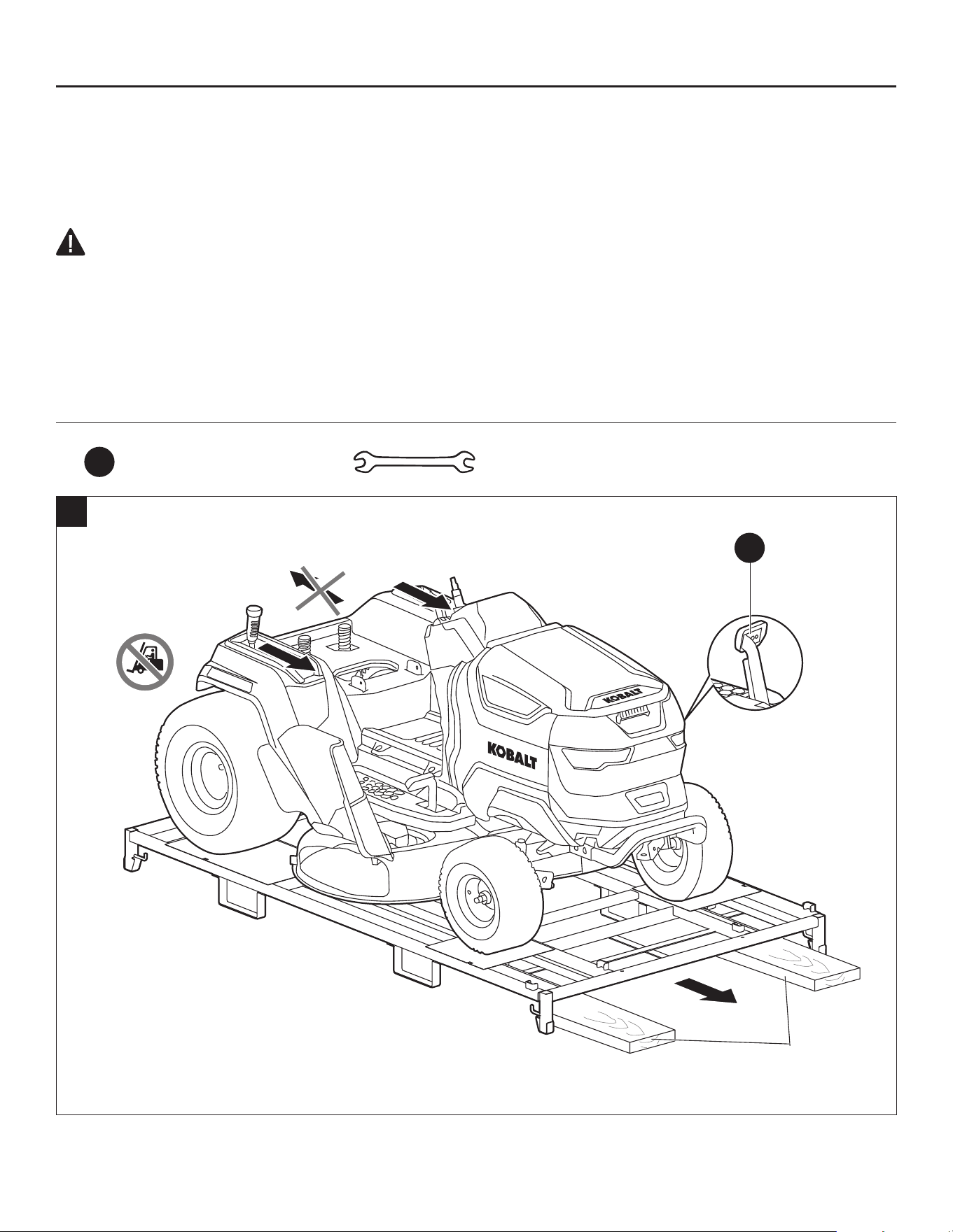
f. If a suitable full-width ramp is available, position it against the bottom frame, close to the front wheels.
Do not exceed the maximum recommend operating angle of 15°. The mower can be removed from
the frame without a ramp. Two pieces of 2x4 lumber help reduce the “drop” from the bottom frame to
the ground.
g. Press the parking-brake pedal (K) to release it from the parking-brake position. A signicant effort is
required to release the parking-brake pedal by hand. Push hard!
CAUTION: Heavy object. Team push required. At least two persons are required to push this
mower off of the steel frame.
h. Grasp the rear corners and the areas around the seat of the mower simultaneously on both sides
and slowly push the mower off of the steel frame in the forward direction (Fig. 1b).
NOTICE: ONLY PUSH THE MOWER FORWARD. Pulling the mower backward from the steel frame
may cause damage to the mower’s cutting deck. Always remove the mower from the frame in the
forward direction!
16
PREPARATION
NOTICE: The mower must be transported on the bottom frame at all times! Fork lift should never
come in direct contact with the mower! Doing so may cause damage. We recommend to keep the
bottom frame to facilitate the transportation of the mower later for service.
i. Cut the nylon strap securing the side discharge chute once the mower is on the ground.
WARNING: Do not use this product if any parts are already assembled to your product when you
unpack it. Parts on the packing list are not assembled to the product by the manufacturer and require
customer installation. Use of a product that may have been improperly assembled could result in
serious personal injury.
• Inspect the product carefully to make sure that no breakage or damage occurred during shipping.
• If any parts are damaged or missing, please contact Kobalt customer service.
Hardware Used
HH
Combination Wrench
13 15
x 2
1b
K
(in released
position)
2x4

17
ASSEMBLY INSTRUCTIONS
2. Installing the Steering Wheel
a. Remove the washer (BB), and M12 nut (AA) from the
accessory bag and set them aside.
b. With the front wheels of the mower pointing straight
forward, mount the steering wheel (V) onto the
steering column by keeping the center line pointing
straight ahead and the at section facing toward the
seat.
c. Slightly rotate the steering wheel (V) until the gear
slot of the mounting hole is aligned with gear of the
steering column.
d. Assemble the washer (BB) and nut (AA). Securely
tighten them using the 18mm socket wrench (GG).
The recommended torque is 29.5-33.2 ft-lbs. (40-45
Nm).
e. Snap the dust cap (W) onto the steering wheel (V)
properly.
Hardware Used
AA
M12 Nut x 1
BB
Washer x 1
GG
18 mm Socket
Wrench
x 1
2
Gear Slot
Steering
Column
Center
Line
Gear
Flat
Section
BB
AA
W
V
18
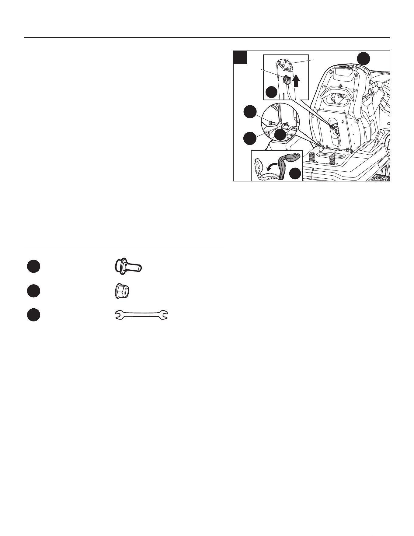
3. Installing the Seat
The mower incorporates a safety interlock system that
will stop the drive motors and blade motors when the
operator is unseated for any reason while the mower is
operating. This is a safety feature designed to prevent
runaway or accidental entanglement.
a. Remove the two sets of step bolt (CC) and M8 nut
(DD) from the accessory bag and set them aside.
b. Lay the seat (X) on its front and align the two mounting
holes with the holes in the suspension base.
c. Insert the two sets of bolt (CC) and nut (DD) and
securely tighten them using the combination wrenches
(HH). The recommended torque is 13.3–14.8 ft-lbs.
(18–20 Nm).
d. Insert the cable plug into the socket on the bottom of
the seat. This connects the safety interlock system.
e. Rotate the seat to lay it onto the suspension base.
Hardware Used
CC
Step bolt x 2
DD
M8 Nut x 2
HH
Combination
Wrench
13 15
x 2
ASSEMBLY INSTRUCTIONS
2
1
3
3
Cable
Plug
Socket
CC
X
DD

19
ASSEMBLY INSTRUCTIONS
4. Charging the Mower
Charge the mower before rst use!
NOTICE: The battery pack is integrated with the product and should not be removed from the product.
CAUTION: DO NOT attempt to charge the mower with a charger not designed for use with
this product.
Use only KOBALT battery charger KRC 752-03 to charge the mower.
4a
Power Cord
and Plug
Charging Cord
and Plug
q
p
J
a. Make sure that the mower comes to a complete stop, turn off the mower, engage the parking brake,
and remove the safety key (EE).
b. Lift the dust cap from the battery charging port (J) on the mower, remove the rubber cover and
connect the charging plug into the port.
NOTE:
The plug will only t one way into the port. Make sure it is properly aligned before inserting.
c. Plug the power cord of the charger into a standard 120 V household outlet.
d. The charger will start charging the battery. The audio indicator will beep once, the "CHARGING" icon
(p) will illuminate on the LCD screen (A1) and the fuel gauge (q) will display the charge level.
e. As soon as the battery is fully charged, the fuel gauge (q) will display "100%", and the "CHARGING"
icon (p) will disappear from the LCD screen (A1). Disconnect the power cord plug from the wall outlet
and remove the charging plug from the charging port (J).
f. Attach the rubber cover and make sure the charging port (J) is properly covered by the dust cap to
protect the charging port from water, moisture, or dust.
20
ASSEMBLY INSTRUCTIONS
WARNING:
• Refer to the manual included with the charger for detailed instructions. Read and understand
all its safety warnings and instructions. Failure to follow them may result in electric shock, re,
and/or serious injury.
WARNING:
• Do not smoke while charging the mower.
WARNING:
• The mower should be charged in a covered area out of the rain or indoors.
NOTE:
• The battery does not develop a memory and does not need to be fully discharged before
recharging.
• Every six months of long-term storage, fully charge the battery for longest possible battery life.
• When charging, be sure that the charger cooling fan inlet and outlet are not blocked.
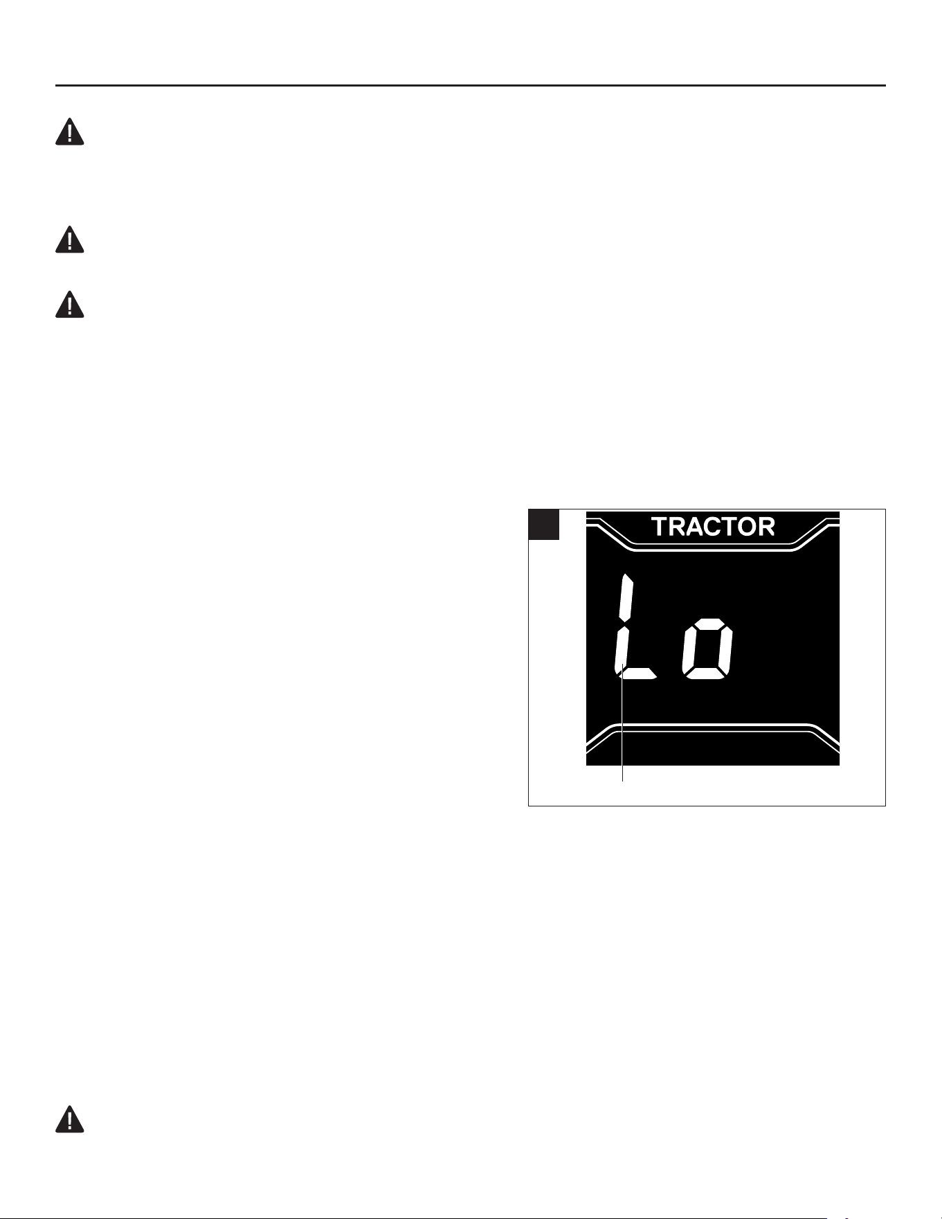
Low power mode
When battery charge becomes critically low, the mower
will go into low power mode to preserve enough power
to travel back to the charging area:
• The blades will switch into low rotation speed, which
could only cut very little amount of grass. Upon
encountering tall and dense grass, the blades will
stop rotating. The audio indicator will sound (beep)
intermittently. The blade on/off button (G1) light will
ash. The "blade on" icon (f) will ash on the LCD
screen (A1).
• The fuel gauge (q) will be replaced with ashing low
battery message on the LCD screen.
The operator should:
• Press the blade on/off button (G1) to turn off the blade motors. The audio indicator will stop
sounding, the blade on/off button light will turn off, and the "blade on" icon (f) will disappear from the
LCD screen when the blade motors stop.
• Stop working and get to the charging area as soon as possible. The maximum distance the mower
can travel is approx. 0.6 mile (0.96 km).
When the battery is nearly depleted, the mower will stop working immediately. The operator will have
to transport the mower to the charging area for charging.
NOTICE: If manual pushing is needed, be sure that the mower is completely turned off, the safety key
(EE) is removed, and the parking-brake pedal (K) is released from the parking-brake position.
WARNING:
• Do not attempt to drive across roads or railways when battery charge level is low.
4b
Low Battery Message
21
ASSEMBLY INSTRUCTIONS
5. Testing the Safety Interlock System
Inspect the entire product for damaged, missing, or
loose parts such as screws, nuts, bolts, caps, etc.
Tighten securely all fasteners and caps and do not
operate this product until any missing or damaged parts
are replaced.
The mower incorporates a safety interlock system that
will stop the drive motor and blade motors when the
operator is unseated for any reason while the mower is
operating. This is a safety feature designed to prevent
runaway or accidental entanglement. Test the system to
be sure it is working correctly.
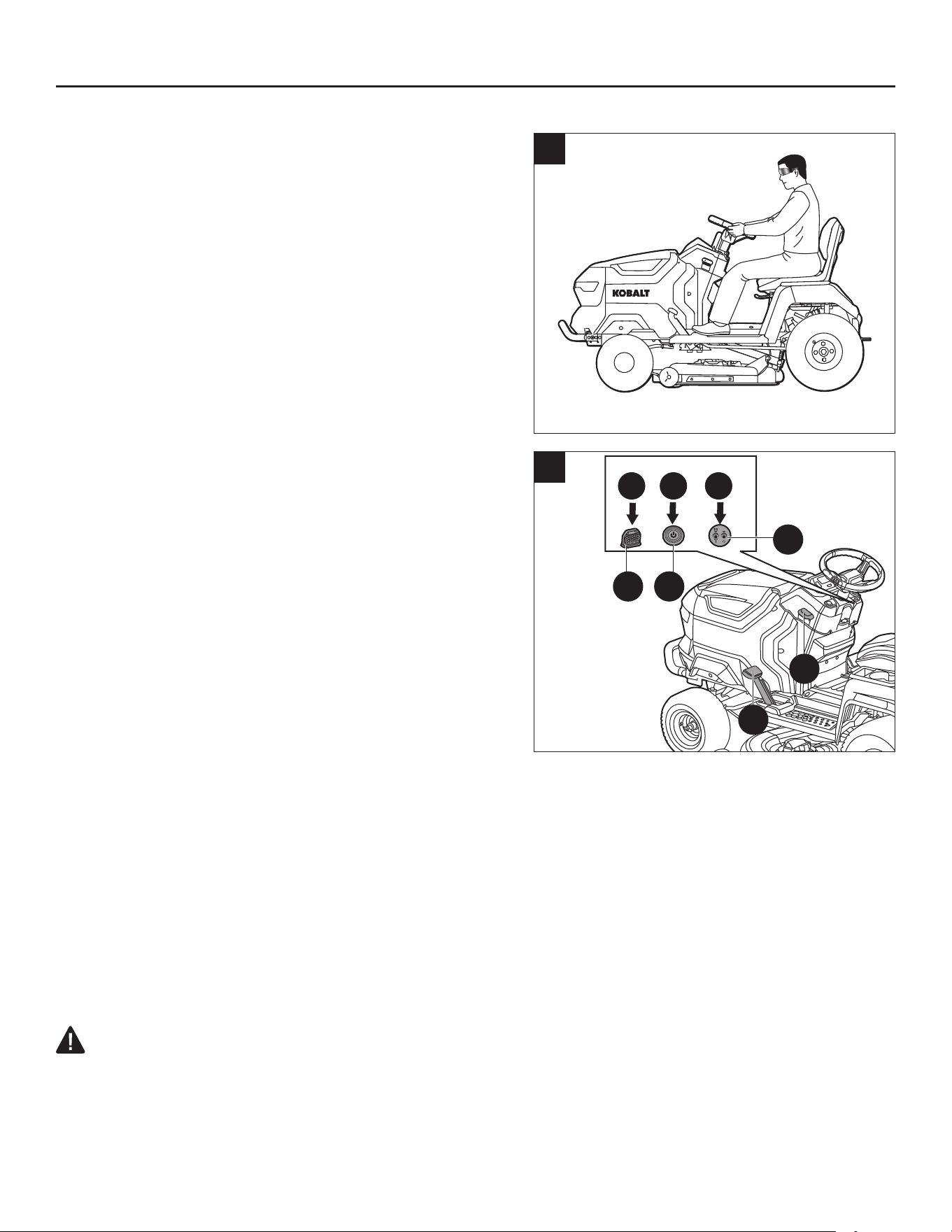
To test the blade operation
a. Position the mower on a level surface.
b. Sit down on the mower seat (Fig. 5a).
c. Insert the safety key (EE) into the mower. Press the start/
stop button (E1) for more than 3 seconds to illuminate
the LCD screen. The LCD screen will illuminate
indicating that the mower is ready for operation.
NOTE:
If the parking-brake pedal (K) is disengaged from
the parking-brake position, you need to fully depress the
parking-brake pedal (K) by foot and press the start/stop
button (E1) for more than 3 seconds simultaneously.
d. Press the blade on/off button (G1) for more than 3
seconds to turn on the blade motors (Fig. 5b), then
release the blade on/off button.
e. Slowly raise yourself off the seat, but do not get off the mower. The blade motors should stop.
NOTICE: If the deck-blade system fails to stop when the operator is off of the seat:
a. Press the blade on/off button (G1) again to turn off the blade motors.
b. With the parking-brake lock lever (M) pulled up, fully depress the parking-brake pedal (K) to engage
the parking-brake.
c. Remove the safety key (EE).
d. Lift the back of the seat and verify that the socket and the plug are properly connected. Refer to step
‘d’ in chapter “Installing the Seat”.
If the cause cannot be determined after conrming the plug and socket are properly connected,
contact Kobalt customer service immediately.
WARNING:
• DO NOT operate the mower until the safety interlock system has been repaired by a qualied
service technician.
5a
>3s
>3s
1 2 3
5b
EE E1
G1
M
K
22
ASSEMBLY INSTRUCTIONS
To test-drive the mower
a. While still seated on the mower, make sure it is on (LCD
screen is illuminated) and (if engaged) disengage the
parking brake by fully depressing the parking-brake
pedal (K) until the parking-brake lock lever (M) drops.
b. Press the driving speed adjustment button (I1) to set
the driving speed to the low level.
c. Pull the direction control lever (D1) backward in the
“D” direction to drive forward.
d. Depress the accelerator pedal (Q) to drive the mower
(Fig. 5c).
NOTE: If the mower does not move, the parking-brake
icon (d) will ash on the LCD screen, which indicates
that you should fully depress the parking-brake pedal (K) and release it, and then depress the
accelerator pedal (Q) to drive the mower.
e. While the mower is moving, slowly raise yourself off of the seat. The driving system should stop the
mower.
NOTICE: If the driving system fails to stop when the operator is off of the seat:
a. Release the accelerator pedal (Q) to stop the mower.
b. With the parking-brake lock lever (M) pulled up, fully depress the parking-brake pedal (K) to engage
the parking-brake.
c. Remove the safety key (EE).
d. Lift the back of the seat and verify that the socket and the plug are properly connected. Refer to step
'd' in chapter “Installing the Seat”.
If the cause cannot be determined after conrming the plug and socket are properly connected,
contact Kobalt customer service immediately.
WARNING:
• DO NOT operate the mower until the safety interlock system has been repaired by a qualied
service technician.
2 3
1
4
5c
I1
D1
M
K
Q
23
OPERATING INSTRUCTIONS
WARNING:
• Do not allow familiarity with this product to make you careless. Remember that a careless
fraction of a second is sufcient to inict serious injury.
• Do not use any attachments or accessories not recommended by the manufacturer of this
product. The use of attachments or accessories not recommended can result in serious personal
injury.
• Before performing any adjustment, stop the mower on a level surface and wait for the blades
to come to a complete stop. With the parking-brake lock lever (M) pulled up, fully depress
the parking-brake pedal (K) to engage the parking brake, then remove the safety key (EE) to
avoid accidental starting and possible serious personal injury.
6. Adjusting the Seat
DANGER: Be sure the seat is secured to the
mower with the step bolts before operating the
mower. A seat that is not secured can cause the
operator to lose control of the mower and result in
possible death or serious personal injury.
Adjust the seat position to ensure you are able to
make rm contact with the parking-brake pedal and the
accelerator pedal before operating the mower.
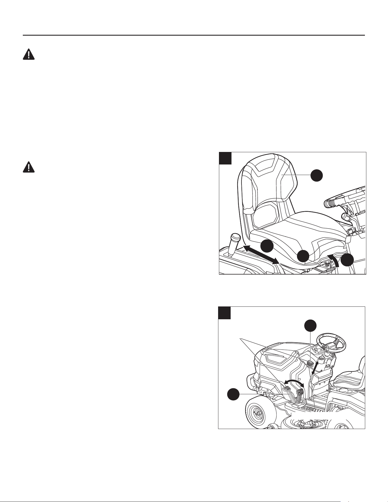
The seat can be adjusted forward and rearward by
rotating the seat position adjustment lever (Y) under the
seat up.
a. Rotate the seat position adjustment lever (Y) up and
hold it, then move the seat (X) forward or backward to the desired position.
b. Release the seat position adjustment lever (Y) and ensure that the seat (X) is locked in position.
7. Setting the Parking Brake
The parking-brake pedal (K) can be used to set the
mower in the parking-brake position. To start the mower,
it should be released from the parking-brake position.
To set the parking brake:
a. Stop the mower on a level surface.
b. With the parking-brake lock lever (M) pulled up, fully
depress the parking-brake pedal (K) until the pedal
stops rebounding.
c. Release the parking-brake lock lever (M). Remove
your foot from the parking-brake pedal (K).
d. To release the parking brake, depress the parking-
brake pedal (K) once again; the pedal will rebound to the released position and the parking-brake
lock lever (M) will drop to released position.
2
1
6
X
Y
7
Parking-brake
position
Released position
M
K
24
OPERATING INSTRUCTIONS
WARNING:
• The parking-brake pedal cannot slow down the driving speed. Never try to depress the
parking-brake pedal to slow down the driving speed during driving. When the parking-brake
pedal is depressed but is not engaged in the parking-brake position, the electric brake is no
longer effective and the mower will stop moving on a at surface. But if this happens on a
slope, the mower may slide down the slope once the parking-brake pedal is released.
WARNING:
• Never leave the mower unattended during work breaks without verifying that the parking
brake is set and the safety key (EE) is removed. Failure to set the parking brake could cause
the mower to move. Leaving the safety key in place may allow unauthorized use that could result in
serious personal injury.
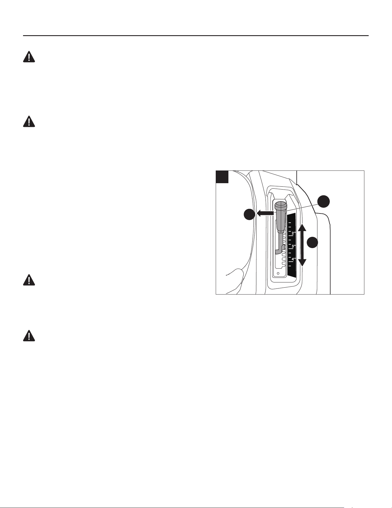
8. Adjusting the Cutting-Deck Height
Prior to mowing, the deck (E) should be adjusted
to sufcient height to avoid stumps, rocks, or other
obstacles that can damage the mower deck.
a. Grasp the deck-height adjustment lever (A) and
move it inwards to disengage it from the detent.
b. Move the lever (A) forward to decrease the cutting
height or backward to increase the cutting height.
Engage the lever (A) into the detent when it arrives at
the desired cutting height.
DANGER:
• Never attempt to make any adjustments to the
mower deck while the mower is driving or the blade motors are turned on. Mower blades
cannot be seen and are located very close to the deck housing. Fingers and toes can be cut off
instantly.
WARNING:
• Hold the deck-height adjustment lever (A) rmly when setting the deck height and only
release when it is securely engaged in the desired detent. Quickly letting go of the lever may
create a pinching or pulling hazard to the operator’s hand.
1
2
8
A
25
OPERATING INSTRUCTIONS
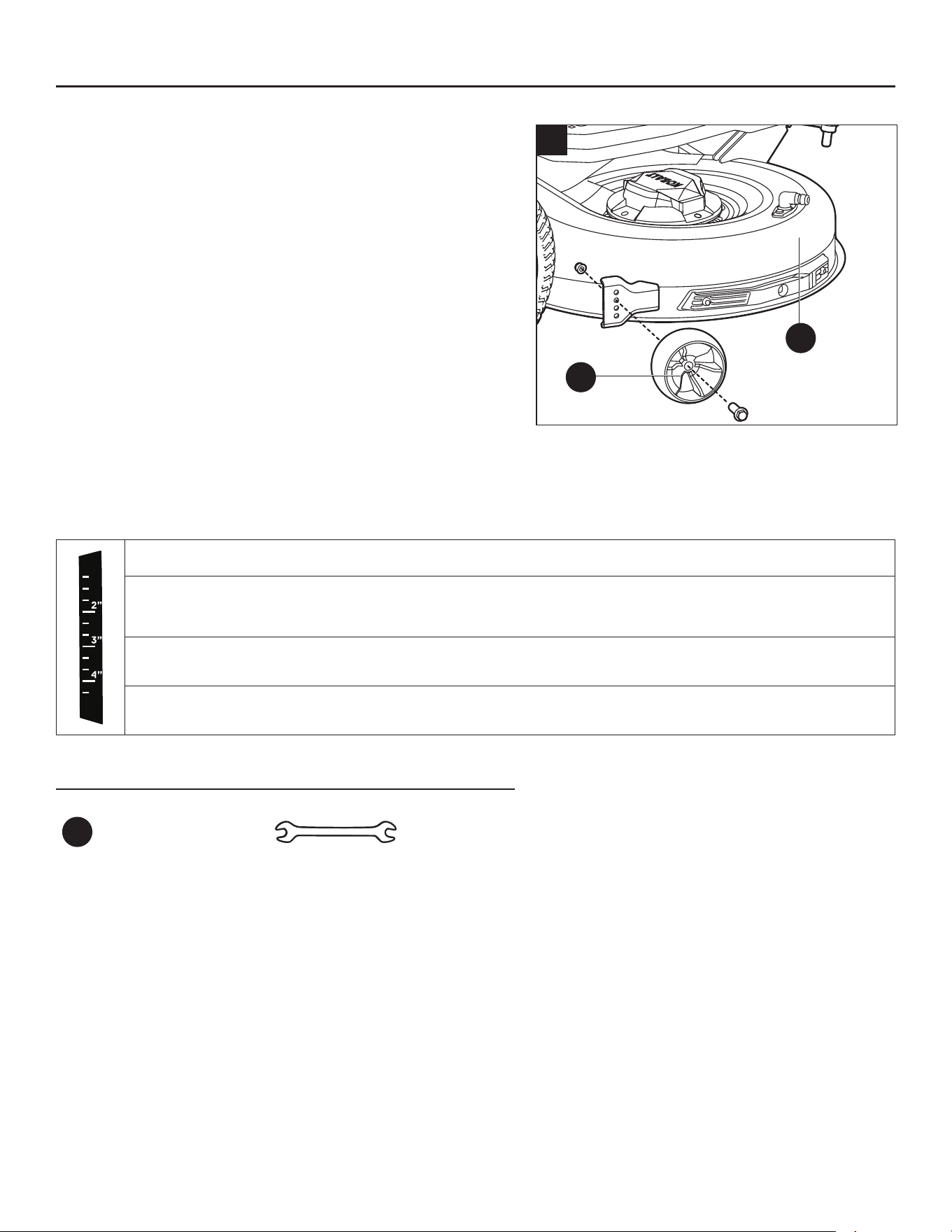
9. Adjusting the Anti-Scalp Wheels
The anti-scalp wheels (G) are designed to minimize the
chance of scalping the lawn when mowing on rough,
uneven terrain. After setting the cutting height, adjust the
anti-scalp wheels so they extend below the deck but do
not contact the ground.
The anti-scalp wheels are held in place by one nut and
lug bolt each. They can be set in one of four positions:
a. Raise the deck (E) to the desired cutting height.
b. Use the 13 mm end of the combination wrench (HH) to
stabilize the nut rst and then loosen and remove the
lug bolt on the other side using the 15 mm end of the
other combination wrench (HH).
c. Move the anti-scalp wheel (G) to the desired position. Then tighten the lug bolt and nut securely. The
recommended torque for the lug bolts is 22-26 ft-lbs. (30-35 Nm).
d. Repeat the steps with the other anti-scalp wheel (G), making sure both wheels are installed in the
same position.
Position 1: less than 2 in. (51 mm) grass cutting height
Position 2: 2 in. – 3 in. (51 – 76 mm) grass cutting height
Position 3: in. – 4 in. (76 – 102 mm) grass cutting height
Position 4: greater than 4 in. (102 mm) grass cutting height
Hardware Used
HH
Combination
Wrench
13 15
x 2
9
G
E
26
OPERATING INSTRUCTIONS
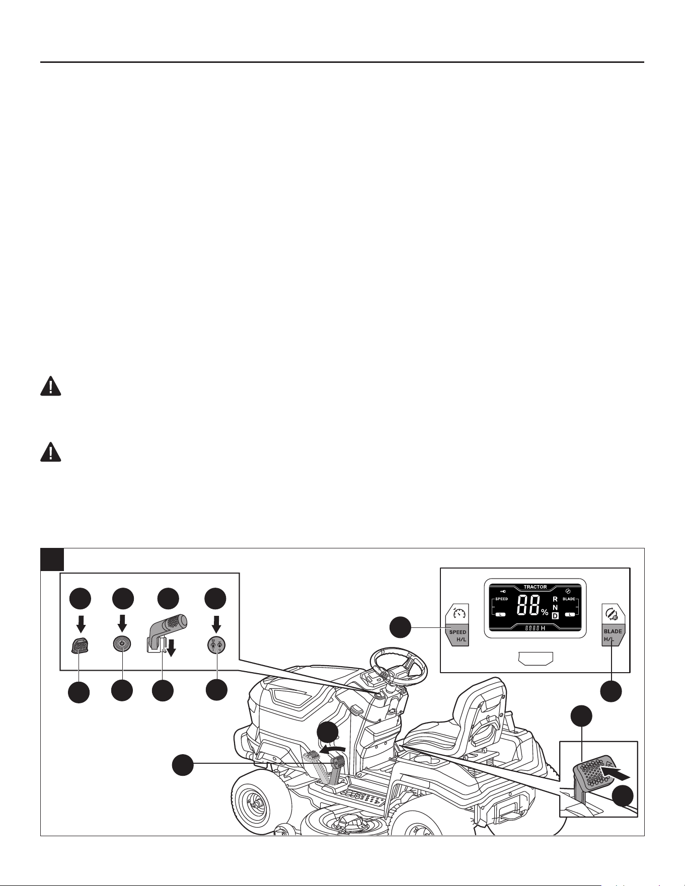
10. Starting the Lawn Mower (Fig. 10a)
Checklist before starting the mower
• Ensure that the work area is clear of children, bystanders, and pets.
• Clear the work area of objects that may be thrown by the mower blades.
• Clean debris from the mower.
• Check for loose fasteners.
• Check to make sure that all guards are in place and working properly.
• Visually check the tires whether they are inated.
• Check the brake operation.
• Adjust the deck height to the desired cutting position best suited for the lawn, and adjust anti-scalp
wheels accordingly.
• Adjust the seat position and make sure both pedals can be reached.
• Verify the battery charge level.
• Test the safety interlock system.
Before you begin to mow grass, we strongly encourage you to nd a large, level, and open area to
practice operating the mower using the instructions that follow. Once you can comfortably and reliably
perform each of these maneuvers, you are ready to begin mowing.
WARNING:
• Clear the area of bystanders before operating the mower. If anyone enters the mowing area, stop
immediately and do not continue mowing until the bystanders leave the area.
DANGER:
• Avoid sudden starts, stops, and turns, as well as excessive speed, especially when rst learning
to operate the mower. The mower can spin rapidly, which may cause you to lose control and could
result in death, serious personal injury and/or damage to the mower. Press the driving speed
adjustment button (I1) to set the low speed level to limit the amount of speed available until you are
fully capable of operating the mower in all situations.
4
>3s
>3s
1 2 3 5
2
4
>3s
10a
EE
E1
I1
C1
Q
D1
G1
K
27
OPERATING INSTRUCTIONS
a. Sit on the mower seat.
b. Insert the safety key (EE).
c. Fully depress the parking-brake pedal (K) by foot and simultaneously press the start/stop button (E1)
for more than 3 seconds to illuminate the LCD screen.
NOTE: If the parking-brake pedal (K) is set at the parking-brake position, you could only press the
start/stop button (E1) for more than 3 seconds to illuminate the LCD screen and then release the
parking-brake pedal (K) before driving the mower.
d. Set the appropriate driving speed and blade speed by pressing the driving speed adjustment button
(I1) and blade speed adjustment button (C1) respectively.
NOTE: It is always recommended to start the mower in the low driving speed.
e. Depress the accelerator pedal (Q) to drive the mower
:
To drive forward: pull the direction control lever (D1) backward in the “D” direction.
To drive in reverse: push the direction control lever (D1) forward in the “R” direction.
NOTE: When you leave the seat, and then sit back on the seat, the mower will not move after
depressing the accelerator pedal (Q) and the parking-brake icon will ash on the LCD screen. In this
case, you need to fully depress the parking-brake pedal (K) and then release it, and then depress the
accelerator pedal (Q) to drive the mower.
f. Press the blade on/off button (G1) for more than 3 seconds to start the cutting blades, then release
the blade on/off button. The button itself will illuminate.
NOTE: For safety reasons, the blades will turn off when pressing the blade on/off button for more than
8 seconds.
NOTE: The cutting blades could be started at any time once the LCD screen is fully illuminated and
the direction control lever (D1) is not pushed forward in the “R” direction. To turn on the blades while
driving the mower in reverse, refer to the section “Turning Blades on While Driving in Reverse” in
this manual.
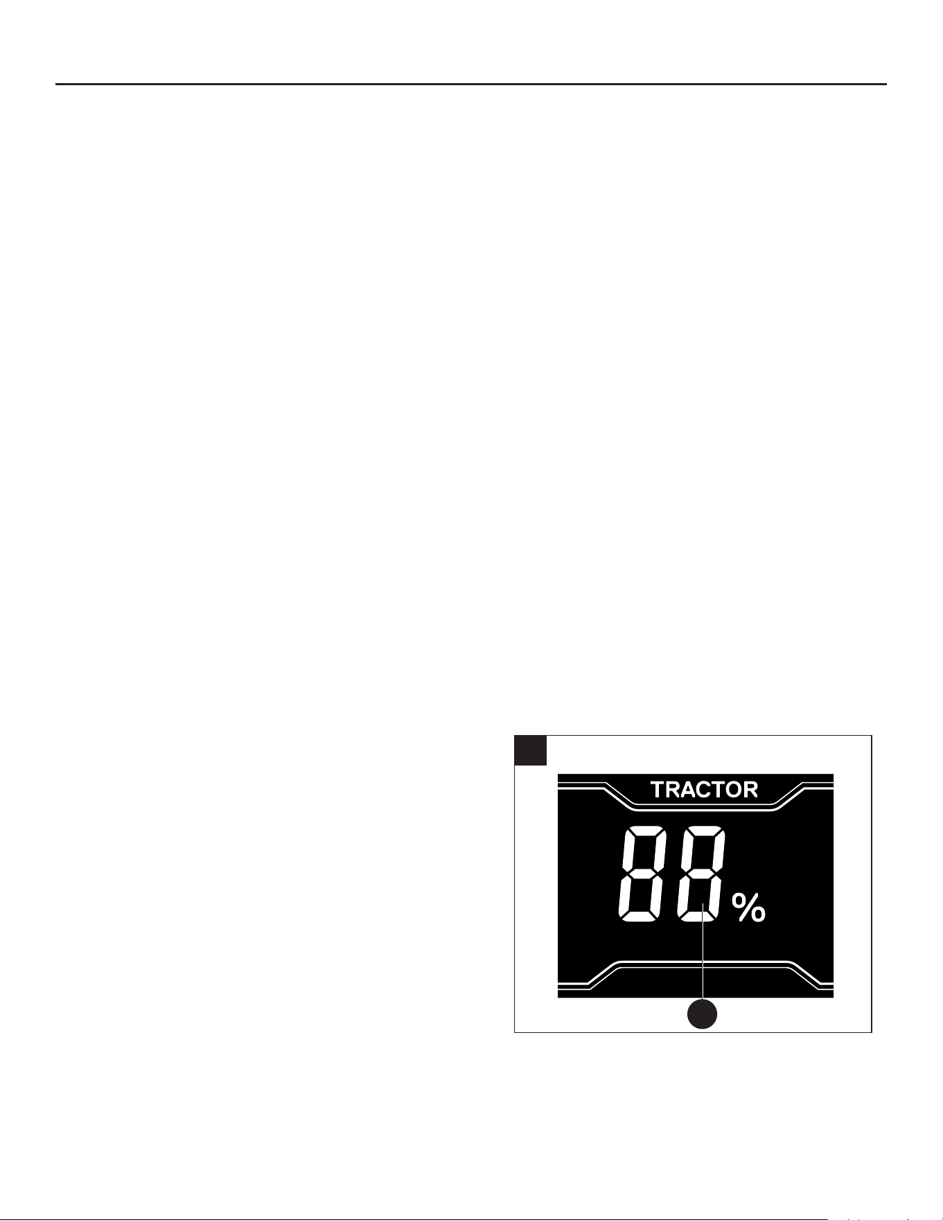
Start/stop button
• Press the start/stop button (E1) briey and the
LCD screen will only display the "fuel gauge" (q)
as shown in Fig. 10b. Press the start/stop button
briey again, the LCD screen will turn off.
• With the safety key (EE) inserted, fully
depress the parking-brake pedal (K) and
simultaneously press the start/stop button (E1)
for more than 3 seconds, the LCD screen will
display full operator interface. Press the start/stop
button again for more than 3 seconds and the LCD
screen will turn off.
10b
q

28
OPERATING INSTRUCTIONS
11. Stopping the Lawn Mower (Fig. 11)
DANGER:
• Never make sudden stops or abrupt changes of direction, especially when maneuvering on a
slope. The steering wheel and accelerator pedal are designed for sensitive response. Quickly
stepping on the accelerator or rotating the steering wheel in either direction could result in a reaction
of the mower that can cause serious injury.
>3s
1
3
5 6
4
2
11
G1 D1 E1
M
K
EE
Q
a. Press the blade on/off button (G1) to turn off the blade motors and the button light will turn off.
NOTE: The cutting blades may be stopped at any time.
b. Release the accelerator pedal (Q).
c. Place the direction control lever (D1) in the “N” position.
NOTICE: Always place the lever in the “N” position when the mower stops driving, which could
prevent unexpected start if the accelerator pedal is depressed accidentally.
d. Pull up the parking-brake lock lever (M) and fully depress the parking-brake pedal (K) to set the
mower in parking-brake position.
e. Press the start/stop button (E1) for more than 3 seconds until the LCD screen is turned off. The start/
stop button light will be off after another 3 seconds, which means the mower is turned off.

29
OPERATING INSTRUCTIONS
f. Remove the safety key (EE) from the mower and keep it in a safe place.
WARNING:
It is recommended for the operator to turn off the mower manually when it is not used, otherwise, the
mower will shut off automatically as described below:
• In a situation when the LCD screen shows the “fuel gauge”, the mower will automatically shut off
after 5 minutes.
• In a situation when the LCD screen shows the operator interface, both the drive motors and blades
motors are not turned on, the mower will automatically shut off after 30 minutes.
WARNING:
• Do not stop the mower on a slope. Always stop the mower on a at, level surface and never leave
the mower unattended with the safety key inserted, even just for a brief period. Leaving the safety
key inserted may allow unauthorized use that could result in serious personal injury.
WARNING:
• When the mower stops driving on a slope and the parking-brake pedal is not set at the parking-
brake position, the audio indicator will continue to beep intermittently to remind the operator to set
the parking brake for safe mower stopping on the slope. Always set the parking brake when leaving
the seat. Otherwise, the mower may slide down the slope, which may cause serious mower
damage or personal injury!

30
OPERATING INSTRUCTIONS
12. Driving The Lawn Mower (Fig. 12)
After starting the mower, follow these instructions:
• To drive straight forward, pull the direction control lever (D1) backward in the “D” direction and
hold the steering wheel (V) straight with no rotation. Control the driving speed with the accelerator
pedal (Q).
• To drive in reverse, push the direction control lever (D1) forward in the “R” direction and hold the
steering wheel (V) straight with no rotation. Control the driving speed with the accelerator pedal (Q).
NOTE: When pulling the direction control lever from the “D” to “R” position WHILE driving forward, the
mower will decrease its speed to zero and then shift in reverse.
NOTE: When switching between forward and reverse during driving, move the direction control lever
directly from one end to the other without stopping in “N” position, otherwise the mower may stop
moving.
• To turn left, rotate the steering wheel (V) to the left.
• To turn right, rotate the steering wheel (V) to the right.
NOTICE: Rapid movement of steering wheel is not recommended as damage to the electric
components of the mower may occur.
NOTICE: Aggressive turning can scuff or damage lawns. Perform turns at low driving speed.
• To stop or decrease speed, release the accelerator pedal (Q) slowly.
• To increase speed, depress the accelerator pedal (Q) all the way. The harder the accelerator pedal
(Q) is depressed, the faster the mower will travel.
DANGER: Stay at least two mowing widths (7 ft /2.13 m) away from any ditches, drop-offs, or
water. Front wheels can rotate when the mower is stopped, even with the brake applied, and cause
the mower to go over the edge or into the water and result in death or serious personal injury.
WARNING: Be aware of what is behind the mower before backing up. DO NOT mow in reverse
unless absolutely necessary. Always look down and behind before and while backing to make sure no
children, bystanders, or pets enter the mowing area. Remember that a careless fraction of a second
is sufcient to inict death or serious injury.
WARNING: Be certain you have correctly set your intended direction of driving with the steering
wheel before depressing the accelerator pedal. Failure to do so could result in you driving the mower
in an unintended direction, which could cause loss of control or an accident.
WARNING: Be cautious when crossing over gravel paths or driveways. Before crossing, turn
off the blade motors and raise the cutting deck to the highest position to minimize the possibility of
ricochet. Drive slowly to avoid loss of traction and control.

31
OPERATING INSTRUCTIONS
D
D
D
R
R
R
12
V
D1
Q

32
OPERATING INSTRUCTIONS
13. Customizing Mowing and Driving Settings
For the best mowing experience, we recommend
customizing the following settings depending on your
situation.
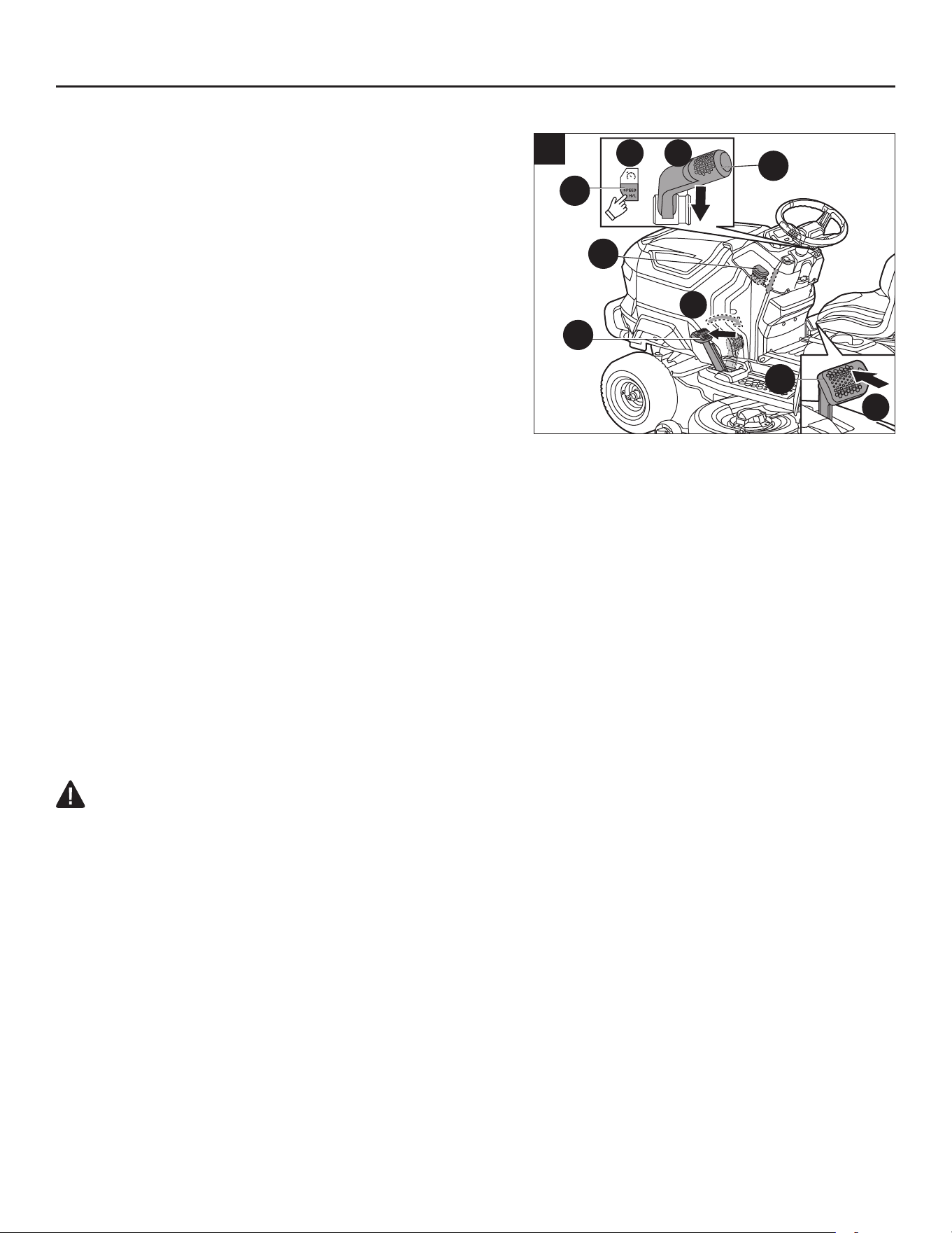
To select your driving speed level (Fig. 13a):
The driving speed level establishes the maximum driving
speed of the mower.
Press the driving speed adjustment button (I1) to toggle
between low level ("L") and high level ("H").
Low driving speed: for low-speed edging and trimming,
or when mowing or driving in tight areas.
High driving speed: maximize the coverage area when
mowing large, at lawns.
To select your blade speed level (Fig. 13b):
The user can customize the blade speed, depending on
grass conditions. Run time will increase when mowing at
low blade speed.
Press the blade speed adjustment button (C1) to toggle
between low level and high level.
Low blade speed ("L"): provides the lowest noise level
and longest run time.
High blade speed ("H"): for tall grass or extremely wet
grass condition.
13a
I1
C1
13b

33
OPERATING INSTRUCTIONS
14. Using Cruise Control (CCS)
During forward driving, the mower could be set to
continue at a desired speed without depressing the
accelerator pedal.
To activate (enter) cruise control (CCS) (Fig. 14)
a. While driving forward at a comfortable speed, press
the CCS button (J1), the CCS icon (a) will illuminate on
the LCD screen.
b. Then release the accelerator pedal (Q) and the mower
will continue driving at the current speed.
NOTE:
The driving speed level shown on the LCD
screen may not accurately represent the actual driving
speed of the mower in cruise control. Press the driving speed adjustment button (I1) to “refresh” the
driving speed level on the LCD screen.
c. Press the driving speed adjustment button (I1) to increase or decrease the cruise control speed until
the desired speed is reached.
To stop (exit) cruise control (CCS), you may choose one of the three ways:
• Depress the accelerator pedal (Q) all the way and keep depressing. The CCS function will stop and
the mower will continue driving.
• Slightly depress the accelerator pedal (Q) and then release it. The mower and the CCS function will
stop.
• Press the CCS button (J1). The mower and the CCS function will stop.
NOTE: When push the direction control lever (D1) forward in the "N" or "R" position, the CCS function
will also stop.
NOTE: When the CCS is stopped, the CCS icon (a) will disappear from the LCD screen.
NOTE: If the parking-brake pedal is depressed, the mower will stop but the CCS icon (a) will ash
on the LCD screen to indicate the CCS is on standby. In this case, release the parking-brake pedal,
press the CCS button (J1), the mower will resume driving automatically and the CCS icon (a) will stop
ashing.
2
1
14
a
I1
J1
Q
34
OPERATING INSTRUCTIONS
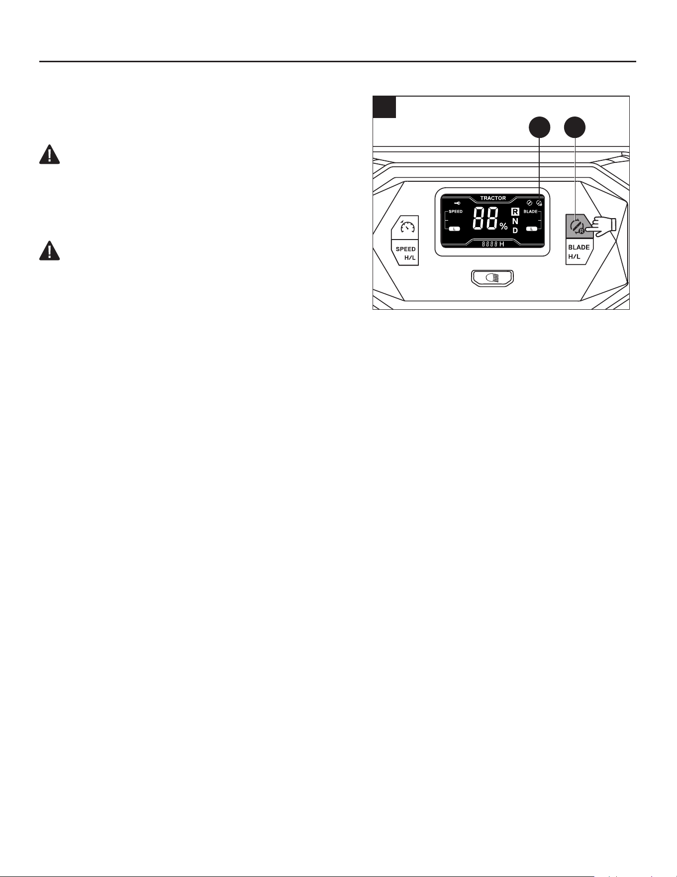
15. Turing Blades on While Driving in Reverse
NOTICE: Mowing in reverse is not recommended
WARNING:
• Use extreme caution when mowing in reverse. Always
make sure no individuals come into the work area,
especially small children, before and while mowing in
reverse.
WARNING:
• The operator’s eld of vision could be limited when
operating the mower with the optional bagger kit
attached. Extreme caution and familiarity with
the surroundings should always be taken into
consideration before and while mowing in reverse.
To activate (enter) mowing in reverse (Fig. 15)
The blade motors can be turned on when driving in reverse, if desired.
After each startup, the mowing in reverse icon (g) will disappear from the LCD screen, which means
the blade motors could not be turned on when driving in reverse.
a. Sit down on the mower seat.
b. Press the start/stop button (E1) for more than 3 seconds and the LCD screen will display operator
interface.
c. Press the mowing in reverse button (B1) for more than 3 seconds and the mowing in reverse icon (g)
will illuminate on the LCD screen, which means the blade motors could be turned on when driving in
reverse.
To stop (exit) mowing in reverse, you may choose one of the four ways:
• Press the mowing in reverse button (B1) once.
• Raise yourself off the mower seat.
• Press the start/stop (E1) button for more than 3 seconds to turn off the LCD screen.
• Remove the safety key (EE) to shut down the mower.
NOTE: When the mowing in reverse is stopped, the mowing in reverse icon (g) will disappear from
the LCD screen.
>3s
15
B1g
35
OPERATING INSTRUCTIONS
16. LED Headlights
The LED headlights (L) could be turned on and off by
the LED light button (H1). The LED headlights icon (e)
will illuminate on the LCD screen.
17. USB-A Port
The USB-A port (U) provides charging power of 5 Volts
DC at up a combined draw of 1.5 Amperes for your cell
phone, MP3 player, or other USB devices. Consult the
owner’s manual for your device for specic charging
requirements.
NOTICE:
• Attempting to charge devices whose combined draws
exceed 1.5 amps could damage the USB port and/or
the mower.
• The USB port could not be powered when the mower
is in charging mode.
• When it is not used, make sure the USB port cover is
closed to protect the USB port from water, moisture, or
dust.
18. Slope operation
See section “Slope Specic” in this manual for safety
instructions before slope operation.
DANGER:
• Slopes are a major factor related to tip-over and roll-over accidents that can result in severe injury
or death. Operation on slopes requires extra caution. If you feel uneasy on a slope, do not mow
it. For your safety, do not attempt to mow steep slopes greater than 15 degrees. Make a copy or
cut out the slope guide image (Fig. 18) and use it to determine if your slope is too steep for safe
operation.
WARNING: Pull up the parking-brake lock lever (M) and depress the parking-brake pedal
(K) immediately to engage it in the parking-brake position in case any emergency occurs. The
mower will stop immediately and will not slide down the slope.
• Mow up and down, not across the face of slopes.
• Do not mow wet grass. Wet grass can cause the tires to lose traction or slip on slopes, even though
the brakes are functioning properly.
• Watch for holes, ruts, rocks, hidden objects, or bumps which can affect your operation. Tall grass
can hide obstacles. Remove all objects such as rocks, tree limbs, etc., which could be thrown by the
blade.
• Do not mow near drop-offs, ditches, or embankments.
• Drive slowly and do not make sudden changes in speed or direction.
16
e
H1
L
17
U

36
OPERATING INSTRUCTIONS
• Avoid stopping on a slope if possible. If stopping on a slope is unavoidable, make sure to engage
parking brake. When restarting, use the lowest possible speed. If turning is necessary, exercise
extreme caution when changing direction and always turn downhill.
• If at any point the tires lose traction while operating on a slope, turn off the blades and proceed
slowly and carefully straight down the slope.
• If using the optional bagger or other accessories, never operate the mower on slope angles greater
than 10 degrees. Use extreme caution and operate the mower slowly when operating on slopes, as
these accessories can change the stability of the mower.
Slope assist
When the mower is restarted on a slope, the moment the accelerator pedal is depressed, the mower
will keep still on the slope without sliding along the slope. Once the accelerator pedal is depressed
harder, the mower will start driving forward normally. This is a function of the Slope Assist feature for
safe starting of the lawn mower.
• When the mower stops driving, the accelerator pedal is released, but the parking-brake pedal is not
set at the parking-brake position. the audio indicator will emit intermittent beeps. The audio indicator
will no longer sound as soon as the parking-brake pedal is set in parking-brake position
.
WARNING: Always set the parking-brake pedal at parking-brake position when the mower stops
driving on a slope, otherwise, the mower may slide down the slope, which may cause serious
mower damage or personal injury!
• When restarting driving on a slope, disengage the parking-brake pedal and depress the accelerator
pedal immediately. Otherwise, when the parking-brake pedal is released but the accelerator
pedal is not depressed, the mower may slide down the slope and the audio indicator will not
beep.
• When driving the mower on a slope, never try to depress the parking-brake pedal to slow down
the driving speed during driving. Otherwise, when the parking-brake pedal is depressed but is
not engaged in the parking-brake position, the mower may slide down the slope once the
parking-brake pedal is released.
37
OPERATING INSTRUCTIONS
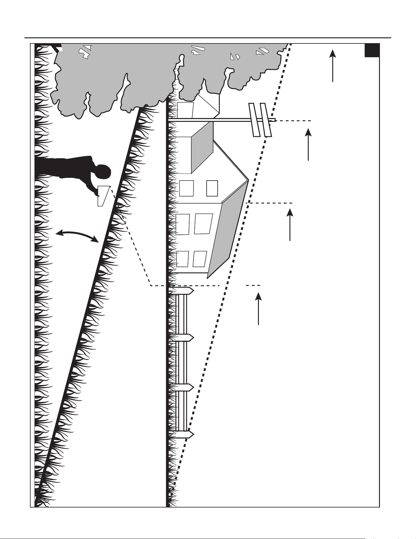
15
o
Sight and hold the line level with a vertical
tree…
Sight and hold the line level with a
pole…
or a corner of a building…
or a fence post
18
Fold along dotted line (represents 15° slope)
38
OPERATING INSTRUCTIONS
19. Mowing Tips
NOTICE: A sharp blade will greatly enhance the
performance of the mower, especially when cutting tall
grass. Make sure to check the sharpness of the blade
before mowing.
• Verify that the lawn is free of stones, sticks, wires, and
other objects which could damage the mower’s cutting
blades or motors. Such objects could be accidentally
thrown by the mower in any direction and could cause
serious personal injury to the operator and to others.
WARNING: If you strike a foreign object, turn off the
mower. Thoroughly inspect the mower for any damage
and repair the damage before restarting and operating the mower. Excessive vibration of the mower
during operation is an indication of damage. The unit should be promptly inspected and repaired.
• The mowing result will be the best with a high blade speed and low driving speed. If the grass is
not too long and dense, the driving speed can be increased without negatively affecting the mowing
result.
• When cutting heavy grass, reduce the driving speed to allow for a more effective cutting and a
proper discharge of the clippings.
• Begin with a high cutting height and reduce it until the desired mowing result is attained. Grass over
6 inches (152 mm) long should be mowed twice, at successively lower cutting heights.
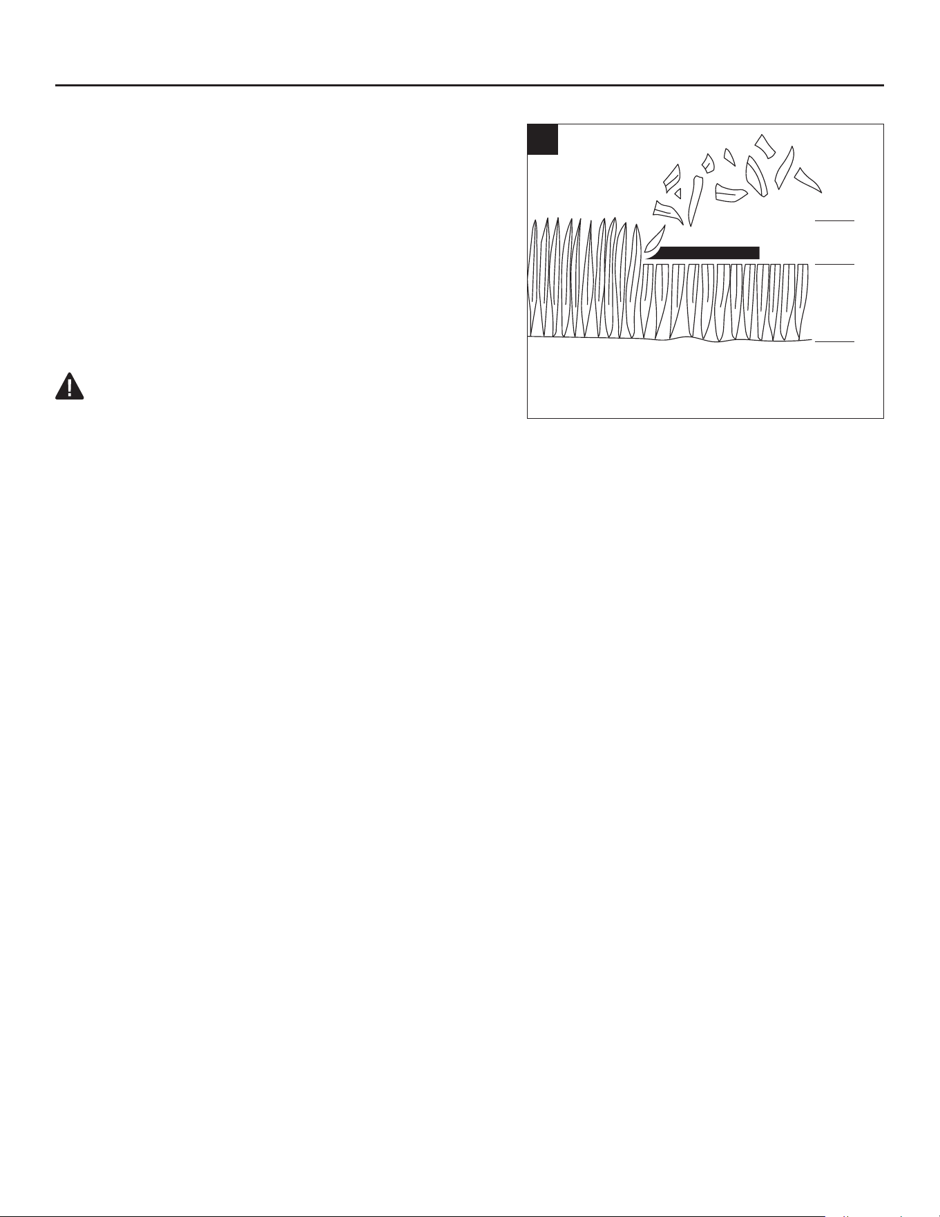
• To maintain a healthy lawn, cut off only one-third or less of the total length of the grass (Fig. 19).
The average lawn should be approximately 1-1/2 to 2 inches (38 – 51 mm) long during cool months,
and between 2 to 3-1/4 inches (51 – 83 mm) long during hot months. For healthier and better-
looking lawns, mow more often after moderate growth.
• Do not cut wet grass. Mowing on wet surfaces can cause loss of control and the wheels to sink
into the soft lawn. Wet grass will stick to the underside of the deck and prevent proper bagging or
mulching of the grass clippings.
• New or thick grass may require a narrower cut or a higher cutting height.
• Keep the mower deck and side discharge chute clean. Remove grass clippings, leaves, dirt, and
any other accumulated debris before and after each use. See section “Cleaning the machine” in
this manual.
20. Tips to Increase Run Time
To get longer run time, please follow these guidelines:
• Cut no more than 1.5 inch (38 mm) of grass in one pass.
• Do not cut wet grass.
• Make sure the blades are sharp.
• Make sure that the underside of the deck is clean.
• Slow down the blade speed – Use the low blade speed level.
• Do not use the mulching plug.
• Do not charge external devices using USB port.
19
1/3
2/3

39
OPERATING INSTRUCTIONS
21. Cold Weather Operation
NOTICE: Under extreme cold weather, the blade motor and driving function may not start
successfully due to the low temperature protection. Please do not make repeated attempts which may
damage the machine. Always store the mower in warm environment. Restart the mower when it is
warmed up. Recommended operating temperature is 32°F–104°F (0°C–40°C).
22. Audio Indicator (Beeps)
The lawn mower is equipped with an audio indicator that will beep in certain situations. It will sound
when:
• The mower starts normally and the LCD screen is illuminated with all icons and indicators. The beep
will sound once.
• The mower is turned off normally. The beep will sound once.
• When starting to drive in reverse or switching the driving direction from forward to reverse while
driving, the beep will sound six times.
• When the available battery charge is critically low, the mower will go into low power mode, the
beeps will continue to sound intermittently until the blade on/off button is pressed to turn off the
blades.
• When the mower is overloaded or overheated, the beep will sound once.
• When any fault codes are displayed on the LCD screen, the beep will sound once.
• When the mower stops driving on a level surface, the accelerator pedal is released, the operator
is off the seat without setting the parking-brake pedal at the parking-brake position, the beeps will
sound continuously to remind the operator to set the parking brake for safety.
• When the mower stops driving on a slope, the accelerator pedal is released, but the parking-brake
pedal is not set at the parking-brake position, the beeps will sound continuously to remind the
operator to set the parking brake for safety.
• When entering or exiting the CCS (Cruise Control System), the beep will sound twice.
• When the mower starts charging successfully, the beep will sound once.
40
CARE AND MAINTENANCE
WARNING: Before performing any maintenance, stop the mower on a level surface and wait for
the blades to come to a complete stop. Engage the parking brake, remove the safety key, and wait
until the start/stop button light is off to avoid accidental starting and possible serious personal injury.
WARNING: To ensure personal safety, never allow people to sit on the machine or operate the
machine while any maintenance is being performed.
WARNING: When servicing, use only identical replacement parts. Use of any other parts may
create a hazard or cause product damage. To ensure safety and reliability, all repairs should be
performed by a qualied service technician.
WARNING: Strictly adhere to all torque wrench tightening specications. Failure to do so could
cause serious personal injury.
NOTICE: Remain alert for unusual noises, as they could be signaling a problem. Visually inspect
the product for any abnormal wear or damage. Periodically inspect the entire product for damaged,
missing, or loose parts such as screws, nuts, bolts, caps, etc., along with wire and string tangles.
Tighten securely all fasteners and caps and do not operate this product until all missing or damaged
parts are replaced.
Maintenance Service
Interval
Maintenance Procedure
Before each use or daily
◾
Check the safety-interlock system.
◾
Visually check the tires whether they are inated.
◾
Inspect the blades.
◾
Inspect the entire product for damaged, missing, or loose parts
such as side discharge chute, screws, nuts, bolts, caps, etc.,
ensuring that all guards are in place and working properly.
◾
Check and make sure the accelerator pedal could be depressed
and released properly.
◾
Check the steering wheel damper. The steering wheel should be
rotated with certain resistance.
After each use
◾
Clean the mower and wash the deck.
Every 25 hours
◾
Check the tire pressure.
Every 100 hours
◾
Check the front wheels, ensuring that the nut is fastened at the
recommended torque 66-68 ft-lbs. (90 – 92 Nm).
◾
Check the rear wheels, ensuring that the 4 lug nuts are fastened
at the recommended torque: 74-76 ft-lbs. (101-103 Nm)
Every 200 hours
◾
Check the front wheels, ensuring that they turn freely.
Every half a year
◾ Check the parking-brake pedal. Pull up the parking brake lock
lever and depress the parking-brake pedal to set the parking-
brake. Manually push the mower forward to see if the mower can
be moved without the rear wheels rotating. If the mower moves
and the rear wheels rotate, please contact Kobalt customer
service and have it repaired by a qualied service technician.

41
CARE AND MAINTENANCE
Maintenance Service
Interval
Maintenance Procedure
Before storage
◾
Remove the safety key from the mower.
◾
Perform all maintenance procedures listed above and thoroughly
clean the mower.
◾
Inspect the entire product for damaged, missing, or loose parts.
Replace or tighten the corresponding ones before storage.
Annually
◾
Lubricate the shaft sleeves of the front wheels. Refer to chapter
“Lubricating the Shaft Sleeves of the Front Wheels”.
GENERAL MAINTENANCE
• Avoid using solvents when cleaning plastic parts. Most plastics are susceptible to damage from
various types of commercial solvents and may be damaged by their use. Use clean cloth to remove
dirt, dust, oil, grease, etc. Insect repellent spray may damage plastic and painted surfaces. Do not
spray insect repellent near the mower.
• Prolonged exposure to sunlight will damage some surfaces.
• Once the mower is left out in the rain accidentally, use dry clean cloth to dry the seat, control panel,
etc., before you restart it or store it.
WARNING:
• Do not at any time let brake uids, gasoline, petroleum-based products, penetrating oils, etc., come
in contact with plastic parts. Chemicals can damage, weaken or destroy plastic which may result in
serious personal injury.
Cleaning the machine
Remove any build-up of grass and leaves on or around the mower housing. Wear eye protection and
use compressed air after each use to clean the mower housing or the top side of the mower.
The underside of the deck should also be cleaned using wash port after each use, as grass clippings,
leaves, dirt, and other debris will accumulate, especially when grass is wet or has high moisture
content. This accumulation is undesirable, as it will harden, restricting blade and air movement,
probably resulting in a poorer quality of cut and even promoting rust and corrosion.
Using wash port to clean the deck
NOTICE: Follow this procedure after EACH USE to prevent buildup and remove corrosive lawn
chemicals.
IMPORTANT: You can wash the machine with a mild detergent and water. Do not pressure wash the
machine. Avoid excessive use of water, especially near the control panel, under the seat, around the
motors and all electric components and bearings.
42
CARE AND MAINTENANCE
a. Set the parking brake. Refer to section “Setting the
Parking Brake” in this manual.
b. Adjust the deck height to the lowest. Refer to section
“Adjusting the Cutting-Deck Height” in this manual.
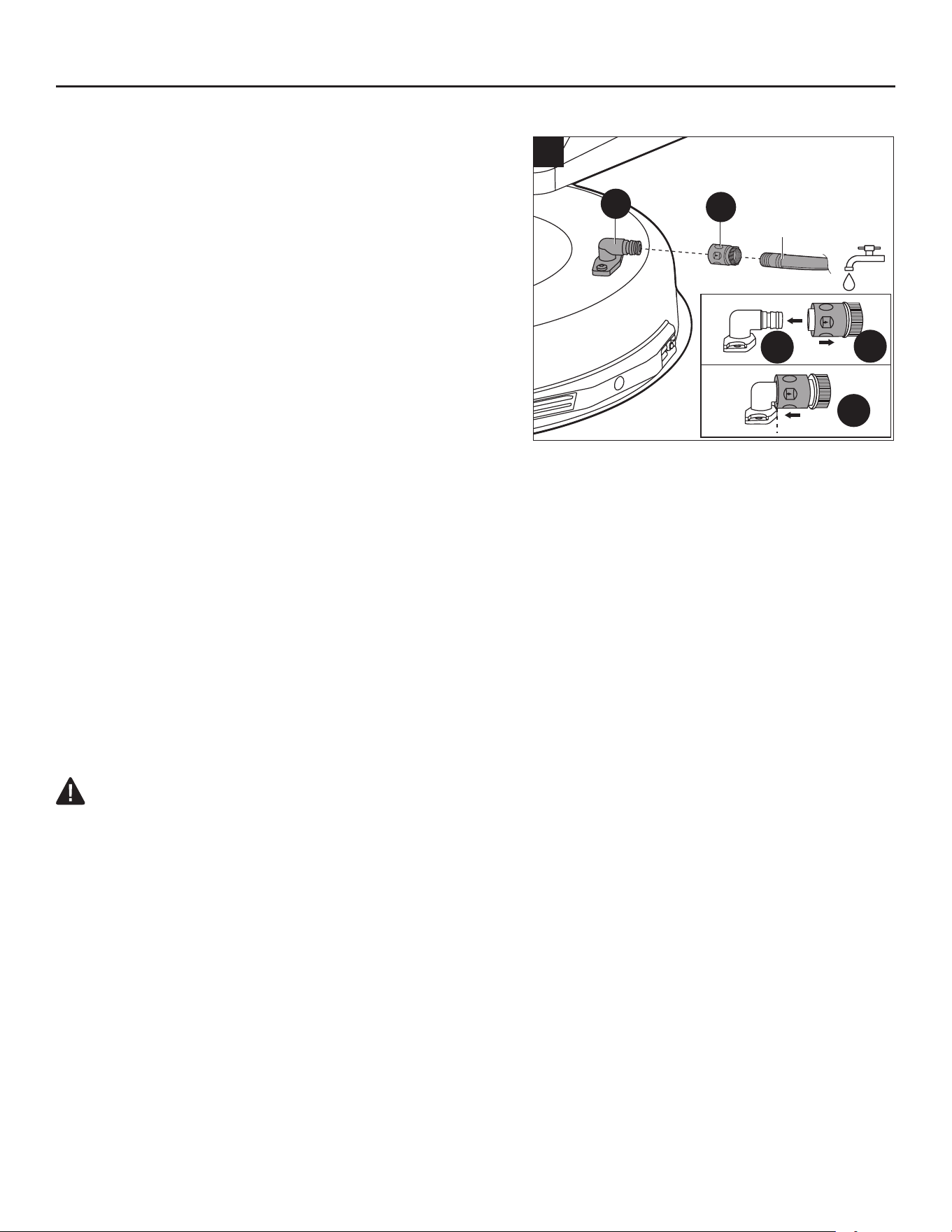
c. Attach the supplied wash-port quick-coupler (FF) to a
garden hose (not included).
d. Attach garden hose with quick-coupler (FF) to the
wash port (D) on the mower deck as shown in Fig. 21
until you hear a clear click. The wash port is on the left
side of the mower deck.
e. Turn on the water.
f. Insert the safety key (EE), depress the parking-brake
pedal (K) and simultaneously press the start/stop
button (E1) for more than 3 seconds to illuminate the
LCD screen.
g. Press the blade on/off button (G1) for more than 3 seconds to start the blade motors and adjust the
blade speed to the high level. Refer to section “To Select Your Blade Speed Level” in this manual.
h. Flush water under the deck for approximately one minute.
i. Turn off the blade motors by pressing the blade on/off button (G1) once again.
j. Turn off the water and remove garden hose and quick-coupler (FF) from wash port.
k. Remove the quick-coupler (FF) from the garden hose and store it in a safe location for future use.
l. Turn off the mower completely. See section “Stopping the Lawn Mower”.
NOTE: When cleaning the deck using the wash port, the mower can be either in mulching or side
discharging mode.
NOTE: If the deck is not clean after one wash cycle, repeat the process until the deck is thoroughly
cleaned.
LEVELING THE DECK
WARNING: Always protect your hands by wearing heavy gloves or wrapping the cutting edges
with rags or other materials when performing any maintenance on the blade(s).
• If your lawn appears unevenly cut after using the mower or when the blade(s) is/are reinstalled, the
deck may need adjusting.
• Before deciding that leveling of the deck is necessary, make sure that the tires are properly inated
to the recommended pressure (please see section “CHECKING THE TIRE PRESSURE” in this
manual). Over- or under- inated tires can affect the appearance of the cut grass, and proper
ination of the tires may be all that is needed to resolve uneven cut issues. If the tires are under or
over-inated, the deck cannot be correctly adjusted.
• Check for bent blades prior to leveling. Remove and replace any bent blades. See section
“REPLACING THE CUTTING BLADES” in this manual for reference.
• Adjust the deck while the mower is on a level surface. Raise the deck to the highest position.
NOTE: Mower deck anti-scalp wheels should not contact the ground when leveling the deck.
NOTE: The deck must be adjusted slightly higher in the rear.
b
2
1
3
20
Garden Hose
D
FF
43
CARE AND MAINTENANCE
Required tools (not supplied): one 13/16 in. (21 mm)
open-end wrench, one 23/32 in. (18 mm) open-end
wrench or adjustable wrench; one leveling gauge.
To make side-to-side adjustment
a. Turn off the mower, engage the parking brake, and
remove the safety key.
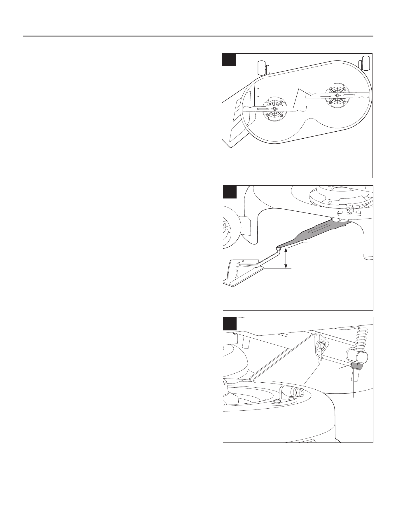
b. Position both blades so that the ends point toward the
sides of the mower (Fig. 21a).
c. On the outside edge of each blade, measure the
distance from the bottom edge of the side of the blade
to the ground (Fig. 21b). If the distance between the
two sides is greater than 13/64 in. (5 mm), side-to-side
adjustment is necessary.
d. On the side you wish to adjust, use a 13/16 in. (21 mm)
open-end wrench or adjustable wrench (not supplied)
to adjust the one jam nut at the rear of the mower
(Fig. 21c).
e. Measure again. Continue to adjust and measure until
the difference between the distances on each side is
within 13/64 in. (5 mm).
f. Proceed to front-to-back adjustment or retighten the
nuts.
NOTE: In case the jam nut on the back is removed from
the machine accidently, remount it with the shoulder of
the jam nut facing outward. No requirement for the two
nuts on the suspension linkage.
21c
Jam Nut
The
shoulder
facing
outward
21b
Leveling Gauge
Bottom edge
of the blade
Distance
21a
Blades side to side
44
CARE AND MAINTENANCE
To make front-to-rear adjustment
NOTICE: Always level the deck side-to-side before
making a front-to-rear adjustment.
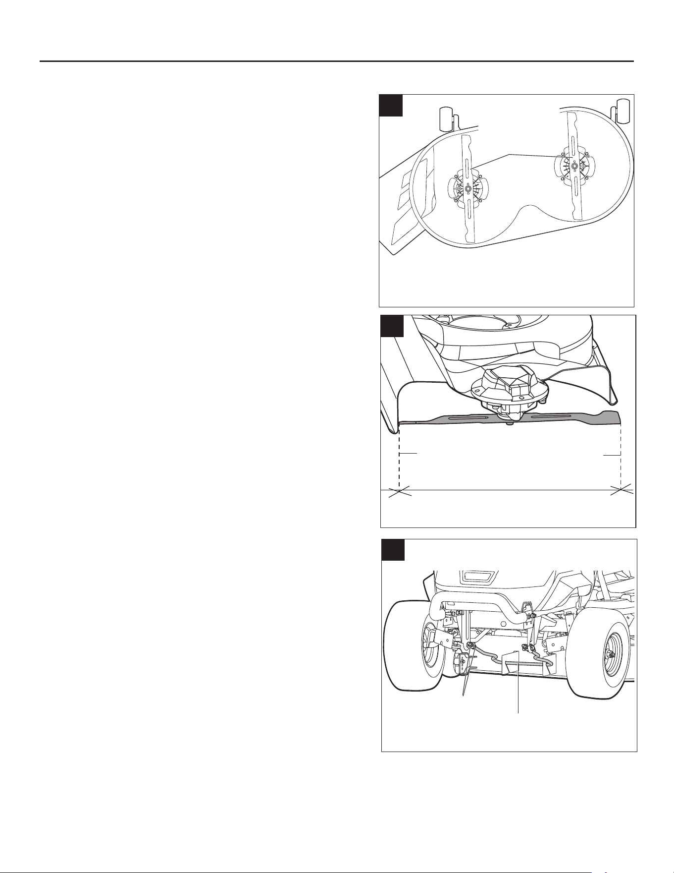
a. Position both blades so that the ends point toward the
front and rear of the mower (Fig. 22a).
b. Measure the distance from the tip of one blade to the
ground (see Fig. 22b). For best results, the front tip of
the blade should be from 5/64 in to 25/64 in.(2 mm to
10 mm) lower than the rear tip.
c. If front-to-rear adjustment is needed, use a 23/32 in.
(18 mm) open-end wrench or adjustable wrench (not
supplied) to adjust the four nuts on the suspension
linkage (two for each side) (Fig. 22c).
NOTICE: Make sure to turn the corresponding nuts
on both sides equally to avoid altering the side-to-side
measurement.
d. Measure again to verify that the front tip is now 5/64 in.
to 25/64 in. (2 mm to 10 mm) lower than the rear tip. If
not, continue to adjust and measure until they are.
e. Retighten the nuts. The recommended torque for the
nuts is 38-42 ft-lbs. (52-57 Nm).
22c
Suspension Linkage
Nuts
22a
Blades front
to rear
22b
Distance from
the front tip to
the ground
Distance from
the rear tip to
the ground
45
CARE AND MAINTENANCE
REMOVING THE DECK
WARNING:
• Make sure that the mower is properly secured and the parking brake is engaged before proceeding.
Follow below steps to remove the deck from the product rst and then perform maintenance.
a. Turn off the mower, engage the parking brake, and remove the safety key.
b. Adjust the deck-height-adjustment lever to the lowest cutting height position.
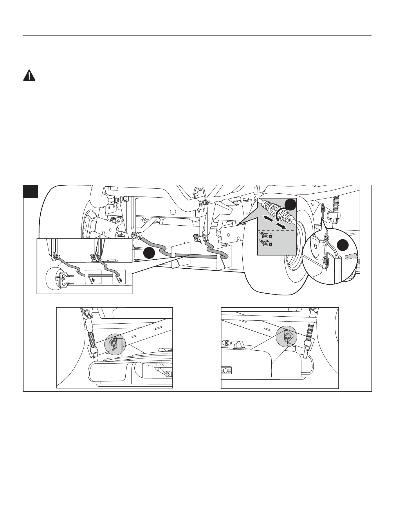
c. Disconnect both blade motor cables.
d. Place a rug or a mat (similar in size to that of the deck) under the deck to prevent the damage to the
deck.
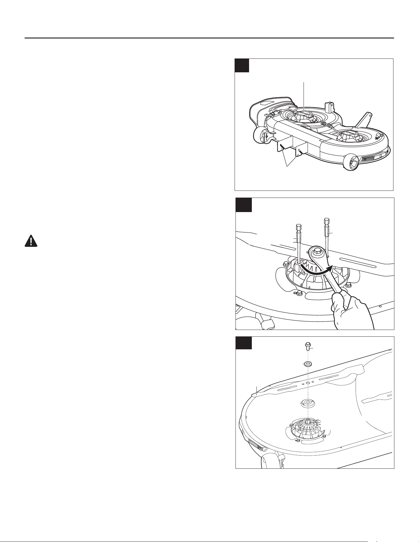
e. Remove the cotter pins and push the shaft pins out. Save both sets for deck re-assembly.
f. Push the deck backward (towards the rear wheels) and rotate the suspension linkage clockwise to
release it from the deck hooks (Fig. 23a).
3
1
2
23a
1.8-1.9 ft-lb
46
CARE AND MAINTENANCE
g. Pull the rug/mat (with the deck on it) sideways to
remove them from under the mower (Fig. 23b).
h. Clean the deck or replace the blade(s) as directed
in “REPLACING THE CUTTING BLADES” in this
manual.
i. When the cleaning or blade replacement is complete,
reassemble the deck onto the mower in the reverse
order.
NOTICE: Reconnect the motor cables, ensuring that
the left motor cable is connected to the left motor while
the right motor cable to the right motor. The cables are
marked with “left” and “right”.
NOTICE: Make sure both motor cables are connected
to the motor with proper torque. The recommended
torque is 1.8-1.9 ft-lbs. (2.4-2.6 Nm).
REPLACING THE CUTTING BLADES
WARNING:
• Always protect your hands by wearing heavy gloves
or wrapping the cutting edges with rags or other
materials when performing any maintenance on the
blade(s). Always remove the safety key when servicing
or transporting the mower.
Required tools:
• Torque wrench with 9/16 in. (14 mm) socket.
• Screwdriver or metal rod 5/16 in. (8 mm) or a little less
in diameter.
• Screwdriver or metal rod 1/4 in. (6.35 mm) or a little
less in diameter
.
Recommended Tools (not supplied): Impact wrench
with 9/16 in. (14 mm) socket make removing the blade
bolts much easier.
To remove the cutting blade
a. Turn off the mower, engage the parking brake, and
remove the safety key.
b. Remove the deck as directed in the section “Removing
the Deck” in this manual.
c. Flip the deck on the ground so that the blades face
upward.
d. While wearing protective gloves, place a screwdriver or metal rod 5/16 in. (8 mm) or a little less in
diameter into the xing hole in the motor to act as a stabilizer 1. Place another screwdriver or metal
rod 1/4 in. (6.35 mm) or a little less in diameter (e.g., a bit) into the aligned hole in the blade and the
ange to act as stabilizer 2 (Fig. 24a).
23b
Blade motor
Deck hook
Bolt
Washer
Flange
24b
Motor Shaft
Blade
24a
Stabilizer 1
Stabilizer 2
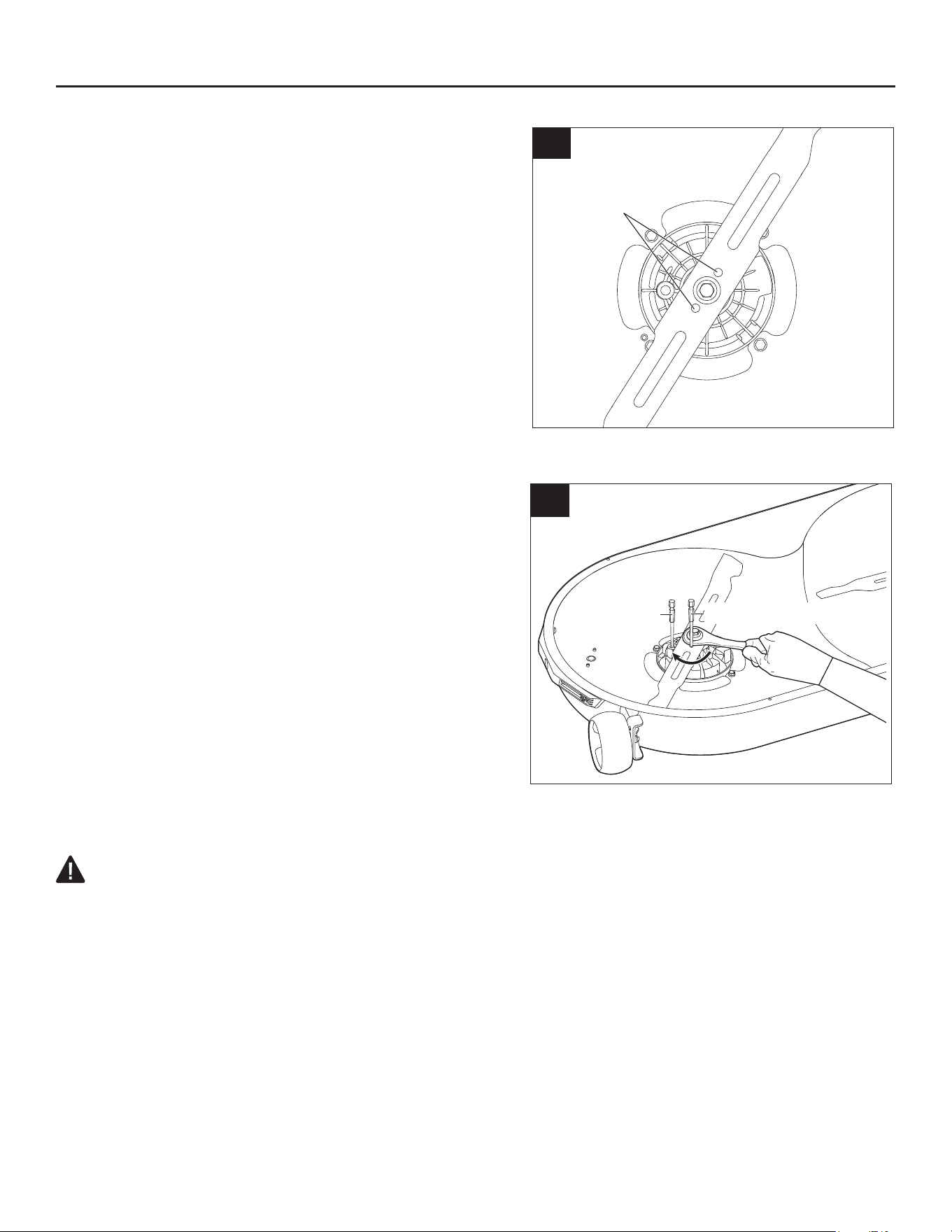
47
CARE AND MAINTENANCE
e. Use a 9/16 in. (14 mm) wrench (not supplied) to turn
the blade bolt counterclockwise to loosen it (Fig. 24a).
f. While wearing protective gloves, remove the bolt,
washer, and the blade (Fig. 24b). The ange can be
left on the motor shaft.
To install the cutting blade
NOTICE: To re-install or replace the blade, make sure
that all parts are replaced in the exact order in which
they are removed (Fig. 24b).
a. If the ange is removed during blade removal, align
it with the motor shaft rst and then assemble it into
place.
b. While wearing protective gloves, position the blade on
the ange with the surface stating “THIS SIDE FACING GRASS” facing toward outside (Fig. 25a).
c. Align the washer with the motor shaft and mount it
onto the motor shaft.
d. Mount the bolt into the motor shaft. Hand-tighten the
bolt clockwise.
e. Move the blade by hand to align the two holes in the
blade with the two holes in the ange (Fig. 25a).
f. Place a screwdriver or metal rod 1/4 in. (6.35 mm)
or a little less in diameter (e.g., a bit) into the aligned
hole in the blade and the ange to act as a stabilizer
1. Place another screwdriver or metal rod 5/16 in.
(8 mm) or a little less in diameter into the xing hole in
the motor to act as a stabilizer 2 (Fig. 25b).
g. Use a 9/16 in. (14 mm) torque wrench to tighten the
bolt clockwise. The recommended torque for the blade
bolt is 36-41 ft-lbs. (50-55 Nm).
h. Repeat the steps with the second blade, if needed.
i. Reassemble the deck onto the mower as directed in “REMOVING THE DECK” in this manual.
WARNING:
• Ensure that the blade is properly seated and the blade bolt is tightened to the torque specications
above. Failure to properly attach the blade could cause it to come loose and result in possible
serious personal injury.
25b
Stabilizer 1
Stabilizer 2
THIS SIDE FACING GRASS
25a
Aligned Holes
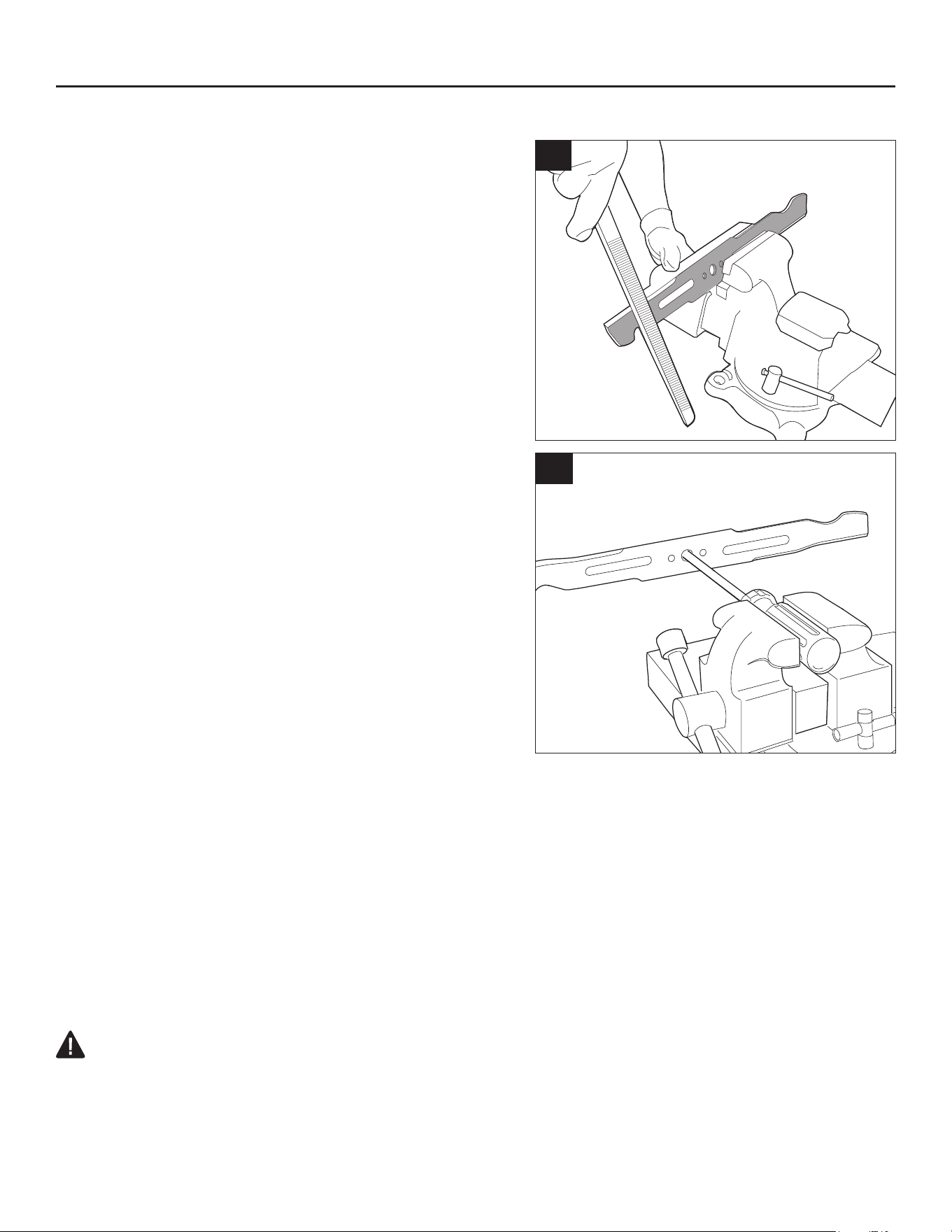
48
CARE AND MAINTENANCE
SHARPENING THE CUTTING BLADE
NOTICE: Keep the blade sharp for best cutting
performance. A dull blade does not cut grass cleanly
or mulch properly. A dull blade can be sharpened,
but a blade that is excessively worn, bent, cracked,
or otherwise damaged must be replaced. A worn or
damaged blade can break, causing blade pieces to
be thrown from the mower. If the blades are found to
be bent, contact Kobalt customer service immediately.
Never attempt to straighten a bent blade by heating, or
weld a cracked or broken blade.
Sharpening frequency
Sharpening the cutting blade twice during a mowing
season is usually sufcient under normal circumstances.
Sand causes the blade to dull quickly; if your lawn has
sandy soil, more frequent sharpening may be required.
When sharpening the cutting blade
a. Make sure that the blade remains balanced.
b. Sharpen the cutting blade at the original cutting angle.
c. Sharpen the cutting edges on both ends of the blade,
removing an equal amount of material from each end.
Sharpening blade in a vise
a. Remove the blade from the mower (please see section
“Replacing the Cutting Blades” in this manual).
b. Secure the blade in a vise (Fig. 26a).
c. Wear proper eye protection and gloves and be careful not to cut yourself.
d. Carefully le the cutting edges of the blade with a ne-tooth le or sharpening stone, maintaining the
original cutting edge angle.
e. To check the blade balance: clamp a nail or a screwdriver with a round shank in the horizontal
position. Position the blade so that the nail or round shank of the screwdriver supports the blade
through its center hole. Balance the blade horizontally. If either end of the blade rotates downward,
remove some metal from the heavy (or lower) end until the blade is balanced. It is balanced when
neither end drops (Fig. 26b).
f. Replace the blade and mount it onto the mower securely (please see section “Replacing the Cutting
Blades” in this manual)
.
WARNING:
• An unbalanced blade will cause excessive vibration when rotating at high speeds. It may cause
damage to the mower and could break, causing personal injury.
26b
26a
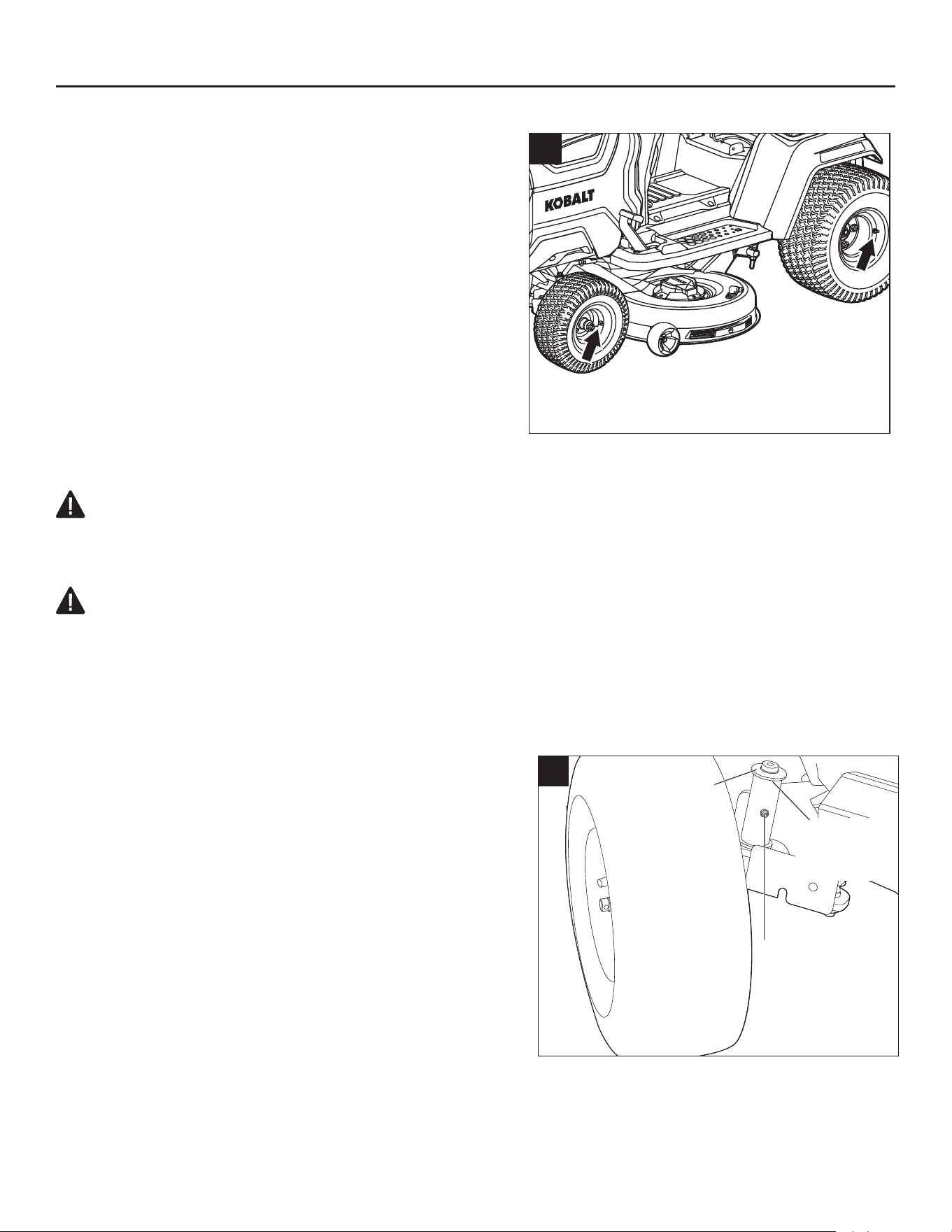
49
CARE AND MAINTENANCE
CHECKING THE TIRE PRESSURE (Fig. 27)
Required tools (not supplied): Tire pressure gauge;
air compressor / inator or heavy-duty bicycle pump.
Check the air pressure in all tires before use. Improper
air pressure will affect handling, steering response,
traction, tire life, level cutting, and operator comfort. Be
sure tires are inated to the pressure as shown in
Fig. 27.
It is important for level mowing that all tires have
the correct amount of air pressure. If the mower is
not tracking straight, please check the air pressure
of the wheels rst.
NOTICE: Tire pressure should only be measured or
adjusted when tires are “cold” (the mower hasn’t been driven yet).
WARNING:
• Check the tire pressure carefully while inating. Too much air in the tire could cause the tire to burst,
causing serious personal injury.
WARNING:
• Maintaining correct air pressure in the tires is very important. Too little pressure could allow the
tire to rotate off the wheel rim. Too much pressure could cause the tire to burst. Failure to maintain
correct air pressure in the tires could cause problems with mower operation and stability, causing
serious personal injury.
LUBRICATING THE SHAFT SLEEVES OF THE FRONT
WHEELS (Fig. 28)
Required tools (not supplied): grease syringe.
The gears of the front wheels need to be lubricated
periodically with gear grease. If the front wheels of the
mower rotate with abnormal noise, remove the safety
key and then ll the injection ports with grease until the
grease overows the upper edge or lower edge of the
shaft sleeves of the front wheels.
同A1机器图
27
14 PSI (96.5 kPa)
10 PSI
(68.9 kPa)
28
Upper Edge
of Shaft
Sleeve
Lower Edge
of Shaft
Sleeve
Injection Port
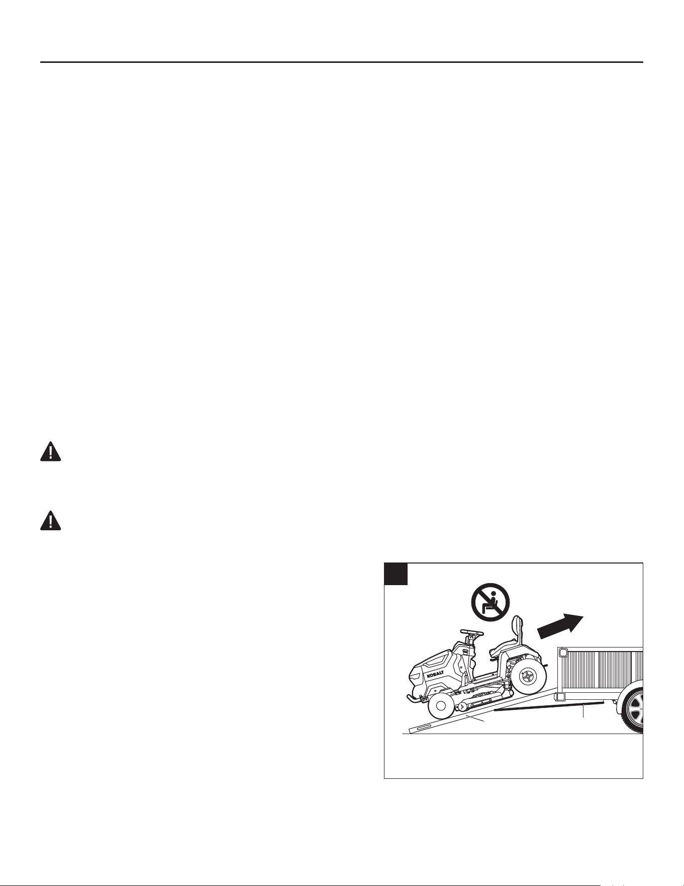
50
CARE AND MAINTENANCE
TRANSPORTING THE MACHINE (Fig. 29)
NOTICE: It is not recommended to tow the machine directly. If necessary, always make sure the rear
wheels of the machine are off the ground during towing. Otherwise, the machine maybe damaged.
NOTICE: When using a forklift, the machine must be transported on the bottom frame at all times!
Forklift should never come in direct contact with the machine!
We recommend to keep the bottom shipping frame to facilitate the transportation of the machine later
for service.
See “TRANSPORT” chapter earlier in this manual for safety instructions before transporting the machine.
Required equipment (not included):
• Full size pickup truck or trailer with the bed that is large enough to t the machine.
• 3 ratchet tie-down straps.
• Measuring tape.
• Bungee cord(s) or rope.
• 2 people.
• 2 dual runner folding ATV ramps with at least 661 lbs. (300 kg) capacity and 12 in. (30.5 cm) width.
The length of the ramp is determined by how high the truck/trailer bed is above ground.
For your safety, make sure that the incline of the ramps is less than 15° whenever possible.
WARNING:
• To reduce the risk of injury and property damage, NEVER drive the machine up or down the
ramp.
WARNING:
• Heavy object. Two people are required to load/unload the machine.
To load the machine onto a truck or trailer
a. Make sure your truck or trailer is parked on a level
surface. The rear of the machine should face the rear
of the truck/trailer.
b. Remove the safety key from the machine.
c. Lift the side discharge chute and secure it in the vertical
position with bungee cord(s) or a rope.
d. Unfold the ramps and visually align the bottom of each
ramp with the center of the corresponding rear wheel.
e. Use the measuring tape to make sure that the top ends
of the ramps are parallel to the bottom ends.
f. Connect one end of the ratchet strap to the safety
chain hook on the truck/trailer. Connect the other end
to the hinge (or middle) of the ramp. Repeat this step with the other ramp.
g. Tighten the straps and make sure the ramps are secure and there’s no movement when you tug on
the ramps or straps.
29
Straps
Ramps

51
CARE AND MAINTENANCE
WARNING:
• Always make sure the ramps are properly secured. Improperly secured ramps may cause the
machine to fall down, causing serious personal injury and damage.
h. Use the measuring tape to once again verify that the ramps are parallel.
i. Make sure the machine’s parking brake pedal is disengaged.
j. Each person should place one hand on the plastic enclosure near the control panel and the other
hand on the rear fender and push the machine up the ramp. NEVER use the steering wheel, the deck
height adjustment lever, or any part of the seat to push the machine.
k. Once the machine is in the bed of the truck/trailer, secure it in place using the tie-down straps. One
strap to secure the front of the machine and two remaining straps to secure the hitch.
l. Use the steering wheel to turn the front wheels to the left or right as far as they will go.
m. Engage the parking brake.
To unload the machine from a truck or trailer
a. Release the tie-down straps and disengage the parking brake.
b. Use the steering wheel to turn the front wheels so they are parallel to the direction of the machine.
c. Unfold the ramps and align the top of each ramp with the center of the corresponding front wheel.
d. Use the measuring tape to make sure that the bottom ends of the ramps are parallel to the top ends.
e. Connect one end of the ratchet strap to the safety chain hook on the truck/trailer. Connect the other
end to the hinge (or middle) of the ramp. Repeat this step with the other ramp.
f. Tighten the straps and make sure the ramps are secure and there’s no movement when you tug on
the straps.
WARNING:
• Always make sure the ramps are properly secured. Improperly secured ramps may cause the
machine to fall down, causing serious personal injury and damage.
g. Use the measuring tape to once again verify that the ramps are parallel.
h. Each person should place one hand on the plastic enclosure near the control panel and the other
hand of the rear fender and carefully lead the machine down the ramp. NEVER use the steering
wheel, the deck height adjustment lever, or any part of the seat to push/support the machine.
STORAGE
The following steps should be taken in order to prepare the mower for storage.
• Every six months of long-term storage, fully charge the battery for longest possible battery life.
• Remove the safety key from the mower.
• Thoroughly clean the mower. See section “GENERAL MAINTENANCE” in this manual for
reference.
• Inspect the mower for worn or damaged parts and tighten any nuts or screws that may have
become loose.
• Store the mower in a dry, clean location. Do not store it next to corrosive materials, such as fertilizer
or rock salt.
• Store the mower in a covered, enclosed space, and out of the reach of children.
NOTICE: Plastic coverings trap moisture around the mower, which causes rust and corrosion.

52
TROUBLESHOOTING
NOTICE: Remove the safety key and then re-insert it a few minutes later to restart the mower before
performing the troubleshooting procedures.
PROBLEM CAUSE SOLUTION
The lawn mower
fails to drive when
the accelerator
pedal is depressed.
◾
The mower battery charge is low.
◾
Charge the mower battery.
◾
The parking-brake pedal (K) is set
in the parking-brake position.
◾
Fully depress the parking-brake pedal
(K) to release it from the parking-
brake position.
◾
The parking-brake icon (d) ashes
on the LCD screen.
◾
Fully depress the parking-brake pedal
(K) and then release it, then depress
the accelerator pedal (Q) to drive the
mower.
◾
The operator is not sitting on the
seat.
◾
The mower can only be operated,
when the operator is fully sitting on
the seat.
◾ The seat safety interlock system is
not connected properly.
◾ Remove the safety key (EE) from the
mower and lift the back of the seat up
to make sure that the cable plug is
properly connected to the socket on
the bottom of the seat (see chapter
“Installing the Seat”). Follow the
instructions in “Starting the Lawn
Mower” to restart the mower to see
if the mower can be started. If not,
please contact Kobalt customer
service and have repairs performed
by a qualied service technician.
◾ Under extreme cold weather,
the driving function may not
start successfully due to the low
temperature protection.
◾ Always store the mower in warm
environment. Restart the mower
when it is warmed up. Please do
not make repeated attempts under
extreme cold weather which may
damage the machine. Recommended
operating temperature is 32°F–104°F
(0°C–40°C).
◾ The travel path of the accelerator
pedal (Q) is clogged with debris.
◾ Check and remove the debris.
◾ Failure of mechanical or electronic
components of the accelerator
pedal (Q).
◾ Please contact Kobalt customer
service and have repairs performed
by a qualied service technician.
◾ The direction control lever (D1) is
placed in the “N” position.
◾ Pull/push the direction control lever
(D1) in the “D” or “R” direction.

53
PROBLEM CAUSE SOLUTION
The lawn mower
stops driving.
◾
When switching between forward
and reverse during driving, the
direction control lever (D1) stays
in the neutral position, "N" for long
time.
◾
Release the accelerator pedal (Q)
and then depress it again.
◾
Failure of electronic components of
the accelerator pedal.
◾
Please contact Kobalt customer
service and have repairs performed
by a qualied service technician.
◾ The seat safety interlock system
got disconnected during driving on
a rough terrain.
◾ Remove the safety key (EE) from the
mower and lift the back of the seat up
to make sure that the cable plug is
properly connected to the socket on
the bottom of the seat (see chapter
“Installing the Seat”). Follow the
instructions in “Starting the Lawn
Mower” to restart the mower to see
if the mower can be started. If not,
please contact Kobalt customer
service and have repairs performed
by a qualied service technician.
◾ The operator’s weight is not evenly
distributed on the seat. The weight
of the operator on the seat must be
at least 44 lbs. (20 kg) for the seat
safety interlock system to function
properly
◾ Sit on the seat properly, fully depress
the parking-brake pedal (K) and
release it, then the mower is ready for
driving.
The lawn mower
fails to start the
blades when the
blade on/off button
(G1) is activated.
The “blade on”
icon (f) on the LCD
screen and the
blade on/off button
light ash.
◾
The battery charge of the mower is
low.
◾
Charge the mower.
◾
The mower is overloaded at the
moment the blades are starting to
rotate, triggering the blade motors
self-protection.
◾
Start the grass cutting at lower blade
speed rst and do not accelerate
the blade speed until the blades are
rotating successfully.
◾
Under extreme cold weather,
the blade motor may not start
successfully due to the low
temperature protection.
◾
Always store the mower in warm
environment. Restart the mower
when it is warmed up. Please do
not make repeated attempts under
extreme cold weather which may
damage the machine. Recommended
operating temperature is 32°F–104°F
(0°C–40°C).
◾
The blade interferes with the
deformed mower deck.
◾
Call Kobalt Customer Service.
TROUBLESHOOTING

54
PROBLEM CAUSE SOLUTION
The lawn mower
fails to start the
blades when the
blade on/off button
(G1) is pressed.
◾
For safety reasons, the blades
will turn off when the blade on/off
button is pressed for more than 8
seconds.
◾
Press the blade on/off button for
more than 3 seconds but not over 8
seconds to turn on the blades.
The blades stop ro-
tating during grass
cutting.
◾
The mower is overloaded.
◾
Raise the deck cutting height or slow
down the driving speed to reduce the
load of the mower.
◾ The deck is clogged with grass
and debris.
◾ Clean the deck and make certain
that the blades have freedom of
movement.
◾ The mower motors/battery are
overheated.
◾ Reduce the load of the mower, by
raising the deck cutting height or
slowing down the blade/driving speed
and allow the mower motors/battery
to cool.
◾ The mower is in low power mode. ◾ When the mower is in low power
mode, the blades are automatically
switched into low rotation speed. The
operator should stop working and
drive to the battery charging area as
soon as possible.
◾
The mower is hit by a foreign
object, resulting in motor self-
protection.
◾
Press the blade on/off button (G1)
to turn off the blade motors and then
press the blade on/off button for more
than 3 seconds to restart them.
◾ The mower moves in reverse with
the mowing in reverse icon (g) not
illuminated on the LCD screen.
◾ Turn off the blade motors and restart
them following the instructions in the
section “To activate (enter) mowing
in reverse”.
The audio indicator
continues beeping.
◾
The mower is in low power mode
and the blades are not turned off.
◾
Press the blade on/off button (G1) to
turn off the blade motors. The audio
indicator will stop sounding when the
blade motors are turned off.
◾
The mower stops driving on a
slope without setting the parking-
brake pedal at the parking brake
position, or the mower stops
driving on the level surface, the
operator is off the seat without
setting the parking-brake pedal at
the parking-brake position.
◾
Set the parking-brake pedal (K) in
the parking-brake position when the
mower stops driving.
TROUBLESHOOTING

55
PROBLEM CAUSE SOLUTION
The start/stop
button light is still
illuminated when
the LCD screen is
turned off for over
10s.
◾
The mower is failed to turn off.
◾
Charge the mower and call
Kobalt customer service for repair
immediately.
The LCD screen
fails to be illumi-
nated with all icons
on.
◾
Start/stop button (E1) has
been depressed for less than 3
seconds.
◾
The LCD screen will only display
the “fuel gauge” when the start/stop
button is pressed briey.
◾
The LCD screen will turn on after fully
depressing the parking-brake pedal
(K) and simultaneously pressing the
start/stop button (E1) for more than 3
seconds.
◾
When the safety key icon (b) is
ashing on the LCD screen, the
safety key (EE) is not inserted.
◾
When the parking-brake icon (d)
is ashing on the LCD screen, the
parking-brake pedal (K) is not fully
depressed.
◾
Insert the safety key (EE), then fully
depress the parking-brake pedal (K)
and simultaneously press the start/
stop button (E1) for more than 3
seconds to turn on the LCD screen.
The mower cuts
unevenly, with
signicant height
difference front to
rear.
◾
The blades are dull.
◾
Sharpen or replace the cutting blades
as instructed in this manual.
◾
The blades are bent.
◾
Replace the bent cutting blades
following the instructions in section
“REPLACING THE CUTTING
BLADES”.
◾
The deck is not leveled, resulting
in different cutting blade height.
◾
Level the deck following the
instructions in section “LEVELING
THE DECK”.
The actual grass
cutting height is not
aligned with the
claimed height.
◾
The deck nuts on the suspension
linkage are loose.
◾
Follow the instructions in section
“LEVELING THE DECK” to make
correct front-to-rear adjustment for
the mower deck and securely tighten
the four nuts on the suspension
linkage (two for each side).
◾
The deck is damaged or seriously
worn.
◾
Follow the instructions in section
“REMOVING THE DECK” to have
mower deck replaced.
TROUBLESHOOTING

56
PROBLEM CAUSE SOLUTION
The mower does
not mulch properly.
◾
Wet grass clippings are sticking to
the underside of the deck.
◾
Wait until the grass dries before
mowing.
◾
The mower is set to cut too much
grass at once.
◾
Raise the deck cutting height.
Excessive
vibration.
◾
The cutting blades are loose.
◾
Tighten the blade bolt to the
recommended torque 36-41 ft-lbs.
(50-55 Nm).
◾
The blades are bent.
◾
Replace the bent cutting blades
following the instructions in section
“REPLACING THE CUTTING
BLADES”.
◾
The deck is not leveled.
◾
Level the mower deck following the
instructions in section “LEVELING
THE DECK”.
◾
The deck nuts on the suspension
linkage are loose.
◾
Use a 23/32 in. (18mm) open-end
wrench (not supplied) to tighten the
four nuts on the suspension linkage
(two for each side).
◾
The deck is set to cut too much
grass at once.
◾
Raise the deck cutting height.
There are grass or
debris remaining
on the ground after
mowing.
◾
The deck is set to cut too much
grass at once when the grass is
tall.
◾
Begin with a high cutting height and
reduce it until the desired mowing
result is attained. Grass over 6 inches
(152 mm) tall should be mowed
twice, at successively lower cutting
heights.
◾
The grass is wet.
◾
Do not mow when the grass is wet.
Wait until the grass dries.
◾
The driving speed is high.
◾
Slow down the driving speed.
◾
The blade speed is low.
◾
Increase the blade speed gradually.
Short run time of
the mower
◾
Lawn terrain, grass conditions,
cutting-height setting, driving
speed, blade speed, etc. will
greatly affect the running time.
◾
Refer to chapter “Tips to Increase
the Run Time” for instructions.
The mower is not
tracking straight.
◾
The tire pressures of the left and
right wheels are different.
◾
Check and adjust the air pressure
in both front and rear wheel tires,
according to section “CHECKING
THE TIRE PRESSURE” in this
manual.
◾
The steering wheel is not installed
properly.
◾
Check and make sure the steering
wheel is installed properly according
to the section “Installing the Seat” in
this manual.
TROUBLESHOOTING

57
PROBLEM CAUSE SOLUTION
The parking-brake
pedal cannot not
be released from
the braking position
or is slow to spring
back.
◾
The travel path of the parking-
brake pedal (K) is clogged with
debris.
◾
Check and remove the debris.
The mower can-
not be charged via
charging port
◾
The plug of the charger is not
inserted correctly into the charging
port (J) on the mower.
◾
Reconnect the charger plug to see
whether the mower can be charged
normally.
◾
There is no power in the wall
outlets.
◾
No action is needed. Wait until the
power recovers.
◾
Charger malfunction.
◾
Please contact Kobalt customer
service and have the charger
inspected and/or repaired, if needed,
by a qualied service technician.
◾
The charging port (J) on the
mower is faulty.
◾
Please contact Kobalt customer
service and have repairs performed
by a qualied service technician.
The mower can-
not be started after
cleaning.
◾
Improper cleaning, such as water
getting on the electric components,
LCD screen, etc.
◾
Follow the instructions in section
“GENERAL MAINTENANCE” to
clean the mower correctly.
◾
The mower caught in rain
accidentally
◾
Leave the mower for over 12 hours to
dry or use compressed air to dry it.
The deck gets
clogged fast.
◾
The deck was not properly cleaned
after previous use.
◾
Clean the mower deck after each
use, following the section “Using
wash port to clean the deck”.
The mower easily
loses traction when
climbing up on the
slope.
◾
The tires of the rear wheels are
worn.
◾
Please contact Kobalt customer
service and have the wheels/tires
replaced by a qualied service
technician.
◾
Mowing on a steep slope.
◾
The mower should not be used to
mow slopes steeper than 15 degrees.
When the mower is
stopped on a slope
with the parking-
brake pedal (K)
engaged, the mower
can roll down the
slope.
◾
The brake components are
excessively worn due to improper
operation of the mower.
◾
Please contact Kobalt customer
service and have repairs performed
by a qualied service technician.
TROUBLESHOOTING

58
PROBLEM CAUSE SOLUTION
There is no water
coming from the
wash port when
attempting to wash
the deck.
◾
The wash-port quick coupler (FF)
is not properly mounted onto the
wash port.
◾
Re-attach the wash-port quick
coupler (FF) until you hear a clear
“click” after rmly pushing. If this
doesn't solve the problem, contact
Kobalt customer service.
An abnormal sound
is heard when
manually pushing
the mower without
starting it.
◾
The sound comes from the
magnets inside the driving motor.
◾
It is normal and no action is needed.
The steering wheel
(V) cannot be ro-
tated.
◾
The steering wheel assembly is
clogged with debris.
◾
Check and remove the debris.
The mower does not
turn left/right when
the steering wheel
(V) is rotated.
◾
Failure of electronic or mechanical
components.
◾
Please contact Kobalt customer
service and have repairs performed
by a qualied service technician.
The mower fails to
stop when releas-
ing the accelerator
pedal (Q).
◾
The return path of the accelerator
pedal (Q) is clogged with debris.
◾
Check and remove the debris.
◾
The CCS button (J1) is pressed
unintentionally while driving. The
mower is in cruise-control mode
◾
Check if the CCS icon (a) is
illuminated on the LCD screen and
exit the CCS as necessary. Refer
to chapter "Using Cruise Control
(CCS)".
The CCS function
cannot be activated
or turned off.
◾
The CCS button (J1) is not
pressed properly.
◾
Press the CCS button (J1) until the
CCS icon (a) is illuminated on the
LCD screen or disappears from the
LCD screen.
◾
The driving speed is too low to
activate the CCS function.
◾
Increase the driving speed and
activate the CCS function again.
TROUBLESHOOTING

59
ICONS AND FAULT CODES ON LCD SCREEN
LCD
Display
Description
Audio
Indicator
Cause Solution
Fuel Gauge (q)
illuminates on the
LCD screen.
No
It indicates the bat-
tery charge of the
mower.
This is normal operation. No ac-
tion is needed.
Hour Meter (o)
illuminates on the
LCD screen.
No
It shows the to-
tal driving time of
mower, in hours and
cannot be reset.
This is normal operation. No ac-
tion is needed.
LED headlights
icon (e) illumi-
nates on the LCD
screen.
No
The headlights are
turned on by the
LED headlights
switch.
This is normal operation. No ac-
tion is needed.
"Blade on" icon
(f) illuminates on
the LCD screen.
No
The blades are
turned on after
pressing the blade
on/off button (G1) for
more than 3 sec-
onds.
This is normal operation. No ac-
tion is needed.
"Blade on" icon
(f) is ashing on
the LCD screen.
No
The blades could not
be turned on after
pressing the blade
on/off button (G1) for
more than 3 sec-
onds.
Check if the mower is overload-
ed or the battery charge is low.
Or restart the mower and turn on
the blades again, if it still fails,
contact Kobalt customer service.
The running of the
blades is interrupted.
Mowing in re-
verse icon (g)
illuminates on the
LCD screen.
No
It indicates the
blades can be
turned on when the
mower moves in
reverse.
This is normal operation. If
needed, turn the blades off while
driving in reverse following the
section “To stop (exit) mowing
in reverse” in the manual.

60
LCD
Display
Description
Audio
Indicator
Cause Solution
CCS icon (a) il-
luminates on the
LCD screen
No
The mower contin-
ues forward at a set
speed without need-
ing to step on the
accelerator pedal.
This is normal operation. If
needed, turn the CCS function
off following the section “To stop
(exit) Cruise Control (CCS)” in
the manual.
CCS icon (a) is
ashing on the
LCD screen.
No
The CCS (cruise
control system) func-
tion has failed.
The CCS function cannot be set
when the mower is driving at
very low speed or is driving in
reverse.
Parking-brake pedal
(K) is depressed to
stop the mower.
After the parking-brake pedal
is released, press the CCS
button and the CCS icon will
illuminate on the LCD screen, or
exit the CCS function following
the instructions in the section
“To stop (exit) Cruise Control
(CCS)”.
Safety key icon
(b) illuminates on
the LCD screen.
No
The safety key (EE)
is inserted correctly.
This is normal operation. No ac-
tion is needed.
Safety key icon
(b) is ashing
when the LCD
screen displays
“fuel gauge”.
The safety key (EE)
is not inserted.
Insert the safety key (EE) then
fully depress the parking-brake
pedal and press the start/stop
button (E1) simultaneously for
more than 3 seconds to turn on
the mower.
Safety key control
panel is damaged.
Please contact Kobalt cus-
tomer service and have repairs
performed by a qualied service
technician.
ICONS AND FAULT CODES ON LCD SCREEN
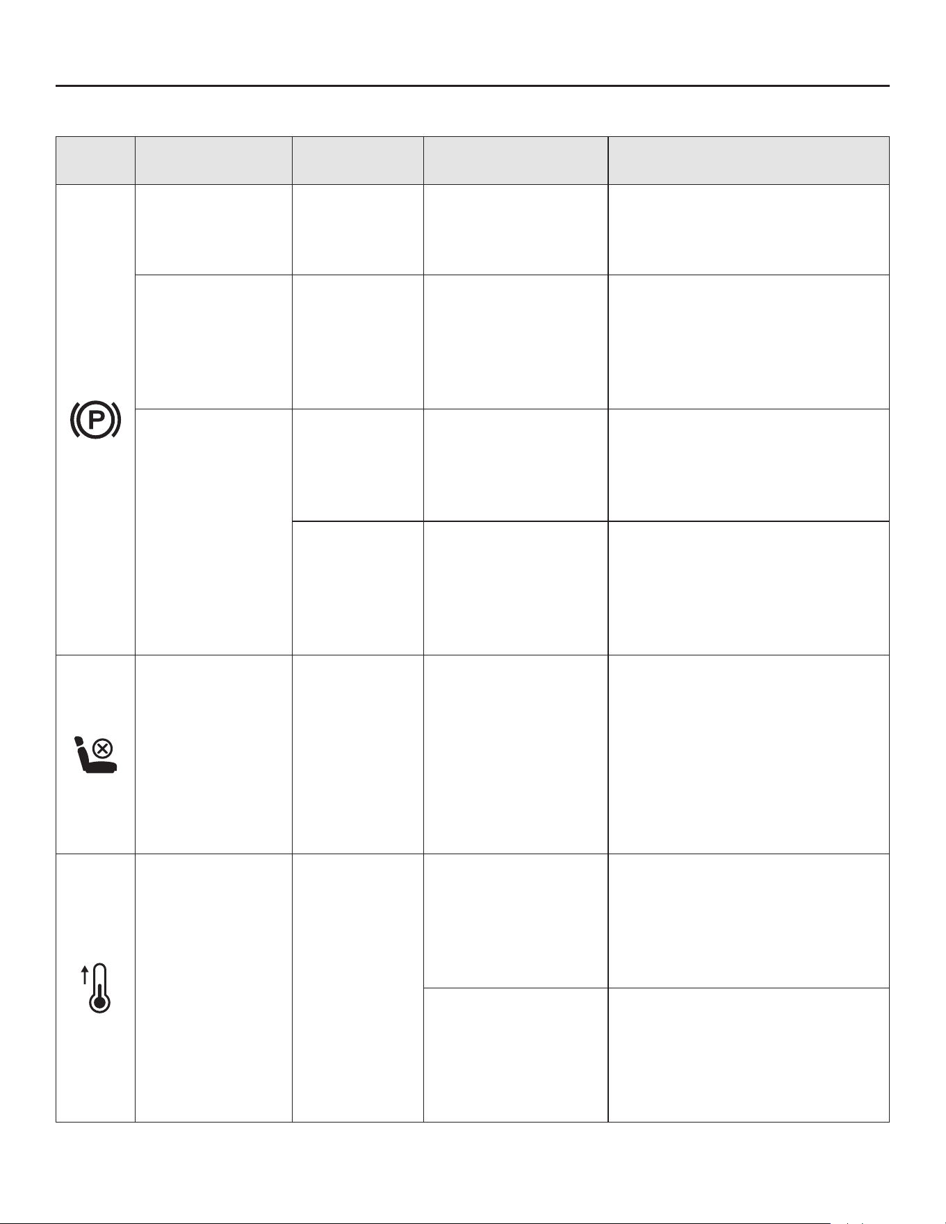
61
LCD
Display
Description
Audio
Indicator
Cause Solution
Parking-brake
icon (d) illumi-
nates on the LCD
screen.
No
The parking-brake
pedal (K) is set at
the parking-brake
position.
Release it before starting the
mower.
Parking-brake
icon (d) is ash-
ing when the
LCD screen
displays the “fuel
gauge”.
No
The parking-brake
pedal (K) is not de-
pressed.
With the safety key (EE) in-
serted, fully depress the parking-
brake pedal and press the start/
stop button (E1) simultaneously
for more than 3 seconds to turn
on the mower.
Parking-brake
icon is ash-
ing (d) when
the LCD screen
displays operator
interface.
No
The operator leaves
the seat, then sits
back to depress the
accelerator pedal to
drive the mower.
Fully depress the parking-brake
pedal (K) and then release it.
Then depress the accelerator
pedal (Q) to drive the mower.
Keeps beep-
ing
The parking-brake
pedal is not set at
the parking-brake
position.
The parking-brake icon (d) will
illuminate on the LCD screen
and the audio indicator will stop
beeping as soon as the parking-
brake pedal (K) is set in parking-
brake position.
Seat sensor icon
(c) illuminates on
the LCD screen.
No
The operator leaves
the seat or the seat
safety interlock sys-
tem is disconnected.
If with the operator is seated on
the seat and the icon is on, stop
operating the mower immediate-
ly and check the seat connec-
tion. If the seat connection with
the mower is conrmed, please
contact Kobalt customer service
and have repairs performed by a
qualied service technician.
The temperature
icon (j) is ash-
ing on the LCD
screen.
One beep
The mower motors/
battery are over-
heated.
Reduce the load of the mower
by raising the deck cutting
height or slowing down the
blade/driving speed. Take a
break and allow the mower mo-
tors/battery to cool.
The mower motors/
battery are too cold.
Please do not make repeated
attempts which may damage
the machine. Always store the
mower in warm environment.
Restart the mower when it is
warmed up.
ICONS AND FAULT CODES ON LCD SCREEN
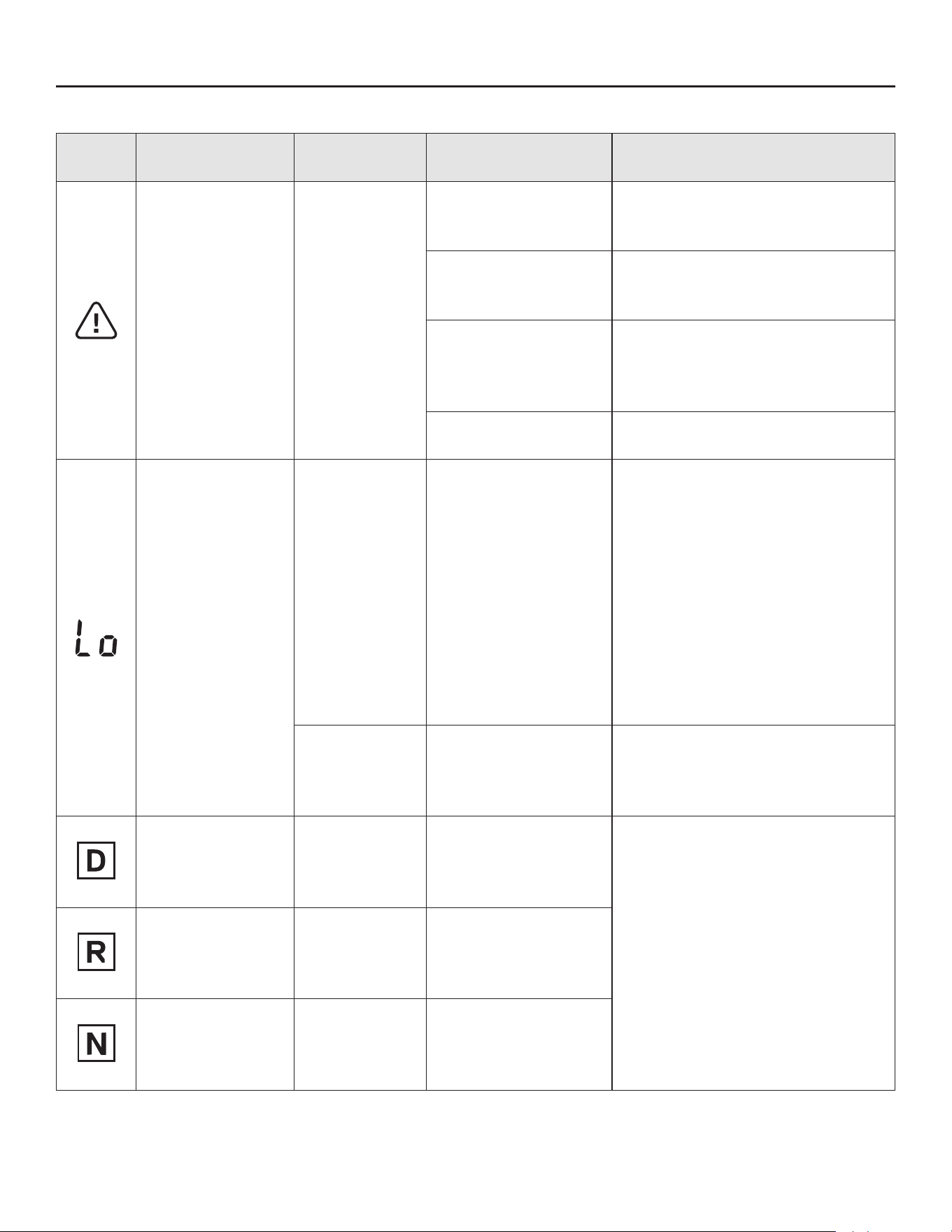
62
LCD
Display
Description
Audio
Indicator
Cause Solution
The alert icon (i)
is ashing on the
LCD screen.
One beep
The blade motor(s)
are overloaded.
Raise the deck cutting height or
slow the driving speed to reduce
the load of the mower.
The side discharge
chute is clogged with
grass and debris.
Clean the side discharge chute
after each use.
There is an inter-
ference between
the blade and the
mower deck.
Please contact Kobalt customer
service.
The driving motor is
overloaded.
Check and make sure the driv-
ing wheels turn freely.
Low battery mes-
sage is ash-
ing on the LCD
screen
Keeps beep-
ing until the
blades are
turned off by
pressing the
blade on/off
button (G1).
The battery is low
on charge and the
mower is in low
power mode.
Stop working and return to the
battery charging area.
NOTE: When the mower is in
low power mode, the blades are
automatically switched into low
rotation speed and meanwhile
the audio indicator will keep
beeping. The operator should
press the blade on/off button to
turn off the blade motors. The
audio indicator will stop beeping
after the blades stop.
Keeps beep-
ing
The battery is nearly
depleted.
The mower will stop working im-
mediately. The operator should
transport the mower to the bat-
tery charging area for charging.
Forward direc-
tion indicator (n)
illuminates on the
LCD screen.
No
It indicates the
mower can be driven
or is driving forward.
This is normal operation. Place
the direction control lever in “D”,
“N”, or “R” position as needed.
Reverse direc-
tion indicator (k)
illuminates on the
LCD screen.
No
It indicates the mow-
er can be driven or
is driving backward.
Neutral direction
indicator (m) il-
luminates on the
LCD screen.
No
It indicates the
mower could not be
driven.
ICONS AND FAULT CODES ON LCD SCREEN

63
LCD
Display
Description
Audio
Indicator
Cause Solution
Low battery mes-
sage and fault
code (r) "102"
are ashing on
the LCD screen.
Keeps beep-
ing
The battery is de-
pleted.
The mower stops working. The
operator should transport the
mower to the battery charging
area for charging.
"CHARGING"
icon (p) and cur-
rent fuel gauge
(q) illuminate on
the LCD screen.
One beep
It indicates the
mower battery is
charging.
This is normal operation. The
"CHARGING" icon will disap-
pear and the fuel gauge displays
100% when the mower is fully
charged.
“CHARGING”
icon (p) and
temperature icon
(j) are ashing on
the LCD screen.
No
The battery of the
mower is overheated
or too cold during
charging.
Wait until the battery returns to
the normal temperature, then
the charging will start automati-
cally.
“CHARGING”
icon (p) is
ashing on the
LCD screen.
No
The mower is not
being charged
properly.
Charge the mower only with the
specied charger.
Charger fault.
Check to see if the charger
self-inspection can be activated
when the charger is plugged in
again or plugged into a differ-
ent outlet. If it still fails, contact
Kobalt customer service
.
Fault code (r)
"509" is ash-
ing on the LCD
screen.
One beep
Left blade motor fails
in rotation
.
Inspect the blade rst. If it is
loosened, use a 9/16 in. (14
mm) torque wrench (not sup-
plied) to tighten the bolt clock-
wise. The recommended torque
for the blade bolt is 36-41 ft-lbs.
(50-55 Nm). Otherwise, please
contact customer service center
and have repairs performed by a
qualied service technician
.
Fault code (r)
"609" is ash-
ing on the LCD
scree
n.
One beep
Right blade motor
fails in rotation
NOTE: For any other fault codes (r) that appear on the LCD screen, which may indicate PCBA failure,
loose connection, motor failure of the driving motor, blade motors, etc., please remove the safety
key and re-insert it a few minutes later to restart the mower. If this doesn’t solve the problem, please
contact Kobalt customer service and have repairs performed by a qualied service technician.
ICONS AND FAULT CODES ON LCD SCREEN

64
ACCESSORY PARTS LIST
PART MODEL NUMBER ITEM NUMBER
Discharge Blade Kit (x2) KLMDB 1052-03
6505203
Bagging Blade Kit (x2) KLMB 1052-03
6505204
Mulch plug KLMMP 1052-03
6505202
Grass Bagger Kit with Rear
Accessory Mount
KLMGB 1052-03 6505201

65
Lowe’s Home Centers LLC.
MOORESVILLE, NC 28117
Printed in China
WARRANTY
Product manufacturer provides the following Limited Warranty for Kobalt Lawn Mower to the original
purchaser of the Kobalt Lawn Mower.
The detailed warranty period for each Kobalt Lawn Mower can be found online on Lowes.com. Please
contact Kobalt Customer Service Toll-Free at 1-888-3KOBALT (888-356-2258) any time you have
questions or warranty claims or would like a hard copy of the warranty.
LIMITED SERVICE WARRANTY
The Kobalt Lawn Mower is warranted against defects in material or workmanship from the date of
original retail purchase for the applicable warranty period. For any properly and timely submitted war-
ranty claim, if Lowe’s determines a product to be defective during the warranty period, the product will
receive free repair or replacement as determined by Lowe’s.
HOW TO OBTAIN SERVICE
For warranty service, within the applicable warranty period, please contact Kobalt Customer Service
toll-free at 888-356-2258 (1-888-3KOBALT). When requesting warranty service, you must present the
original dated sales receipt. An authorized service center will be selected to evaluate and repair the
product if defective according to the stated warranty terms. When bringing your product to the autho-
rized service center, there may be a small deposit that will be required when dropping off your tool.
This deposit is refundable when the repair service is deemed to be covered under warranty. The pur-
chaser is responsible for transportation of the Kobalt Lawn Mower or attachments at their expense.
ADDITIONAL LIMITATIONS & EXCLUSIONS
This limited warranty applies only to the original purchaser from Lowe’s and is not transferable. The
Kobalt Lawn Mower shall not be considered defective, and this warranty will not apply, where the
claimed defect is attributable to any cause other than the above-defined defects. This warranty shall
be void if the product has been used for rental purposes. This warranty shall not apply to damage
caused by accident, abuse, misuse, alteration, modification, unauthorized repair, liquid contact, fire,
earthquake or other external cause; operating the product outside The Kobalt Lawn Mower’s instruc-
tions, specifications or guidelines; or failure to properly service or maintain the product. This war-
ranty also does not apply to cosmetic damage, including but not limited to scratches or dents; defects
caused by normal wear and tear or otherwise due to the normal aging of the product.


Número de serie
Fecha de compra
ARTÍCULO #5974766
MODELO #KLMR 4252B-03
TRACTOR PODADORA
DE CÉSPED DE LITIO
MÁXIMO DE 42 PULG.
ADJUNTE SU RECIBO AQUÍ
¿Preguntas, problemas, piezas faltantes? Antes de volver a la tienda, llame a
nuestro Departamento de Servicio al Cliente al 888-3KOBALT (888-356-2258),
de lunes a domingo de 8 a.m. a 8 p.m., hora estándar del Este. También puede
ponerse en contacto con nosotros en [email protected].
KOBALT y el diseño del logotipo son marcas
comerciales o marcas registradas de LF, LLC.
Todos los derechos reservados.

68
ÍNDICE
Contenido del paquete ...........................................................69
Aditamentos ...................................................................73
Información de seguridad ......................................................... 74
Preparación ...................................................................81
Instrucciones de ensamblaje ......................................................84
Instrucciones de funcionamiento .................................................... 91
Cuidado y mantenimiento ........................................................109
Solución de problemas ..........................................................123
Garantía. . . . . . . . . . . . . . . . . . . . . . . . . . . . . . . . . . . . . . . . . . . . . . . . . . . . . . . . . . . . . . . . . . . . . . 139
ESPECIFICACIONES DEL PRODUCTO
COMPONENTE ESPECIFICACIONES
Voltaje 52 V
Tamaño de la plataforma 42 pulg.
Tamaño de las ruedas
Delanteras 15 x 6 - 6 pulg.
Traseras 20 x 10 - 8 pulg.
Presión de neumáticos “en
frío”
Delanteras 14 PSI (96.5 kPa)
Traseras 10 PSI (68.9 kPa)
Velocidad de la cuchilla hasta 3000 RPM
Velocidad máxima de con-
ducción
Avance Hasta 5.5 mph (8.8 km/h)
Reversa Hasta 2.7 mph (4.4 km/h)
Ajuste de la altura de corte (12 posiciones) 38.1 – 114.3 mm (1.5 – 4.5 pulg.)
Peso máximo de remolque (peso rodante
total)
272 kg (600 lb)
Grado de protección de ingreso (IP) IPX4 (protección contra las salpicaduras)
Temperatura de carga recomendada 5 °C a 40 °C (41 °F a 104 °F)
Temperatura de operación recomendada 0 °C a 40 °C (32 °F a 104 °F)
Temperatura de almacenaje recomendada -20 °C a 70 °C (-4 °F a 158 °F)
Peso 190 kg (419 lb)
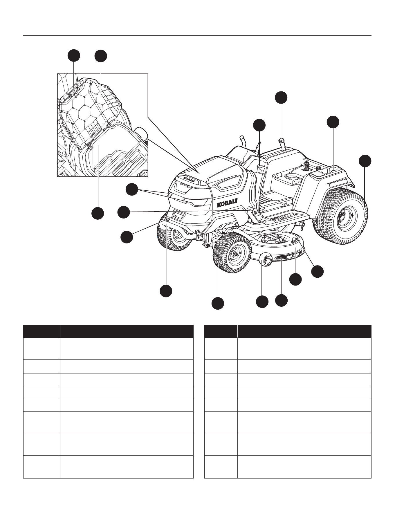
69
CONTENIDO DEL PAQUETE
L
O
P
N
M
A
B
C
E
F
G
H
I
D
J
K
PIEZA DESCRIPCIÓN PIEZA DESCRIPCIÓN
A
Palanca de ajuste de altura de la
plataforma
I Parachoques frontal
B Portavasos y espacio de almacenamiento J Puerto de carga
C Rueda trasera (rueda motriz) (x2) K Pedal del freno de mano
D Puerto de lavado L Faro LED (x2)
E Plataforma M Palanca de bloqueo del freno de mano
F Protector de cubierta N
Botón de liberación de la cubierta del
compartimiento de almacenamiento
G Rueda protectora (x2) O
Cubierta del compartimiento de
almacenamiento
H Rueda delantera (x2) P
Compartimento de almacenamiento:
capacidad máxima: 30 kg (66 lb)
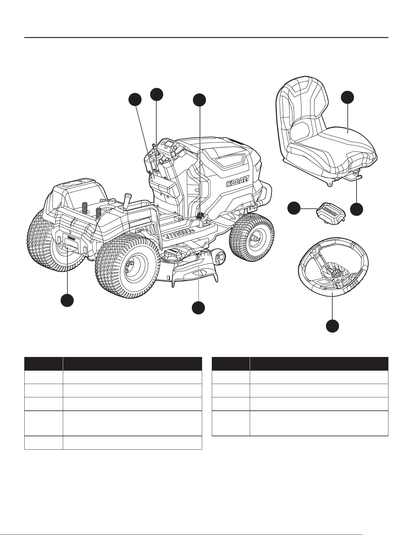
70
CONTENIDO DEL PAQUETE
U
T
S
Q
R
V
Y
W
X
PIEZA DESCRIPCIÓN PIEZA DESCRIPCIÓN
Q Pedal acelerador V Volante
R Conducto de descarga lateral W Cubierta contra polvo
S Enganche X Asiento
T Caja para almacenamiento Y
Palanca de ajuste de la posición del
asiento
U Puerto USB tipo A

71
CONTENIDO DEL PAQUETE
I1
J1
G1
F1 E1
D1
A1 B1
C1
H1
PIEZA DESCRIPCIÓN PIEZA DESCRIPCIÓN
A1 Pantalla LCD F1 Ranura para llave de seguridad
B1 Botón de corte en reversa G1
Botón on/off (encendido/apagado)
de las cuchillas
C1
Botón de ajuste de velocidad de las
cuchillas
H1 Botón de los faros LED
D1 Palanca de control de dirección I1
Botón de ajuste de velocidad de
conducción
E1 Botón de arranque/apagado J1 Botón de control de crucero (CCS)

72
CONTENIDO DEL PAQUETE
s
a b c d e f g
k
h
i
nmopqr
PIEZA DESCRIPCIÓN PIEZA DESCRIPCIÓN
a Ícono de control de crucero (CCS) j Ícono de temperatura
b Ícono de llave de seguridad k Indicador de dirección de reversa
c Ícono del sensor del asiento m Indicador de dirección neutral
d Ícono del freno de mano n Indicador de dirección hacia delante
e Ícono de los faros LED o Contador horario
f Ícono de “cuchillas encendidas” p Ícono de “CARGANDO”
g Ícono de “corte en reversa” q Indicador de combustible
h
Indicador de la velocidad de las
cuchillas
r Indicador de código de falla
i Ícono de alerta s
Indicador de velocidad de
conducción
NOTA: El texto “TRACTOR” en la pantalla LCD equivale al nombre del producto “MOWER”
(PODADORA).
NOTA: Consulte la sección “ÍCONOS Y CÓDIGOS DE FALLA EN LA PANTALLA LCD” para obtener
más información sobre los Íconos e indicadores en la pantalla LCD.
j
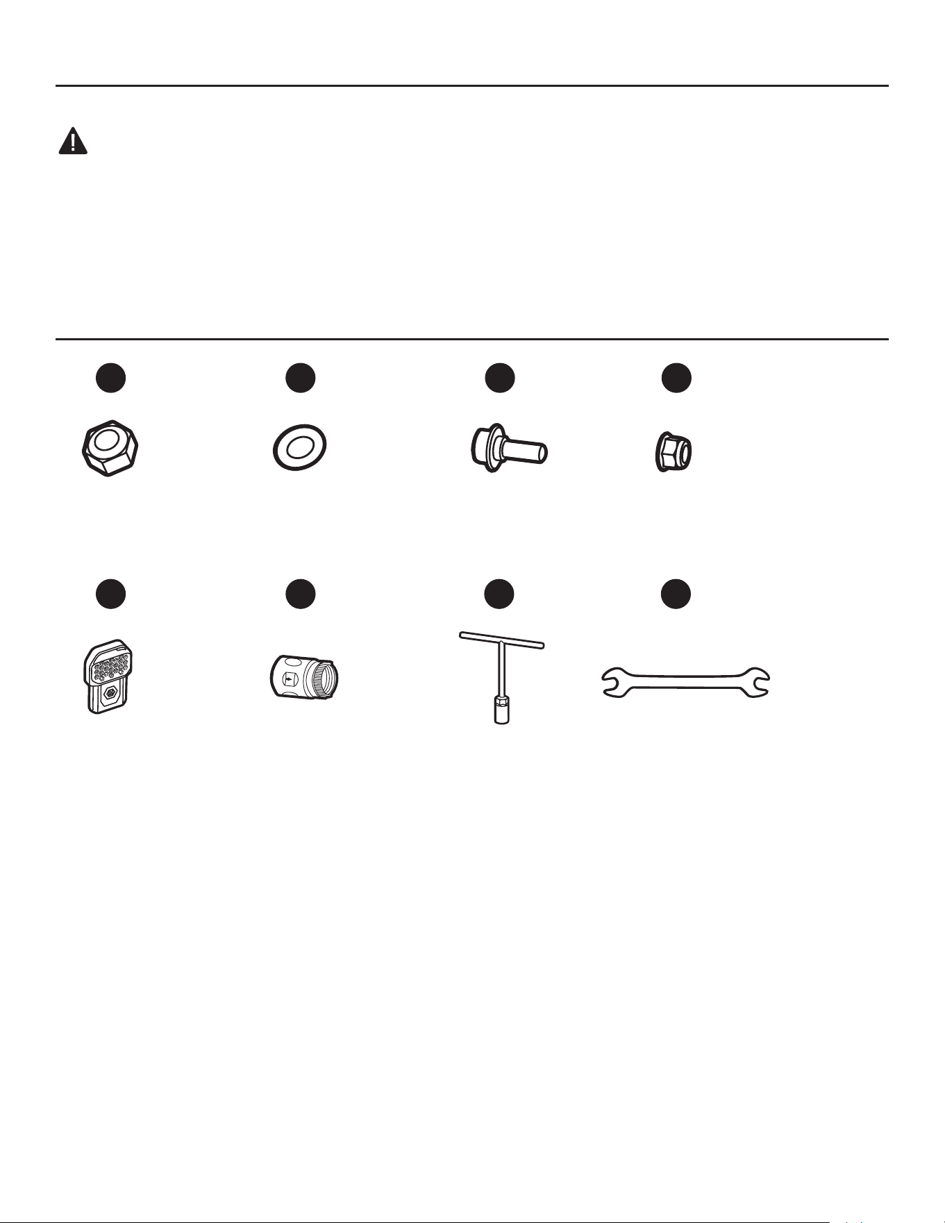
73
CONTENIDO DEL PAQUETE
ADVERTENCIA:
• Retire la máquina del paquete y examínela cuidadosamente. No deseche la caja ni ningún material
de embalaje hasta que haya examinado todas las piezas.
• Si falta alguna pieza de la máquina o si está dañada, no la use hasta reparar o reemplazar dicha
pieza. Si no tiene en cuenta la presente advertencia, podría resultar gravemente herido.
ADITAMENTOS (NO SE MUESTRAN A ESCALA)
Tuerca M12
Cant. 1
Arandela
Cant. 1
Perno de cuello
cuadrado
Cant. 2
Tuerca M8
Cant. 2
Llave de
seguridad
Cant. 2
Puerto de lavado con
acoplador rápido
Cant. 1
Llave de tuerca de
18 mm
Cant. 1
Llave de
combinación
Cant. 2
13 15
AA
EE FF GG HH
BB CC DD

74
INFORMACIÓN DE SEGURIDAD
Antes de intentar ensamblar o utilizar el producto, asegúrese de haber leído y comprendido este
manual por completo.
ADVERTENCIA:
• La operación de cualquier herramienta eléctrica puede arrojar objetos extraños a los ojos y, de esta
manera, causar graves daños oculares. Use siempre lentes o gafas de seguridad con protecciones
laterales y, cuando sea necesario, un protector facial que cubra todo el rostro antes de comenzar a
operar una herramienta eléctrica. Recomendamos usar una máscara de seguridad de visión amplia
sobre los lentes o gafas de seguridad con protecciones estándar. Siempre use lentes de protección
que cumplan con la norma ANSI Z87.1.
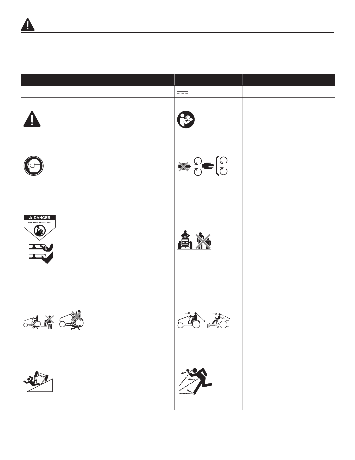
75
INFORMACIÓN DE SEGURIDAD
Algunos de los siguientes símbolos pueden aparecer en esta máquina. Obsérvelos y aprenda su
signicado. La interpretación correcta de estos símbolos le permitirá utilizar la máquina de manera
más ecaz y segura.
SÍMBOLO DEFINITION SÍMBOLO DEFINITION
V Voltios
o CC Corriente continua
Peligro, advertencia o
precaución. Signica
"¡Atención! Está poniendo
en riesgo su seguridad”.
Para reducir el riesgo
de lesiones, el usuario
debe leer el manual de
instrucciones.
Siempre use gafas o
lentes de seguridad con
protecciones laterales y un
protector facial que cubra
todo el rostro cuando
opere este producto.
No abra ni retire los
protectores de seguridad
mientras el producto está
en funcionamiento.
Mantenga las manos y los
pies alejados de las piezas
giratorias para reducir
el riesgo de lesiones.
No opere la unidad a
menos que la cubierta
de descarga o la bolsa
para césped estén en su
lugar adecuado. Si están
dañadas, reemplácelas de
inmediato.
No pode cuando haya niños
u otras personas alrededor.
Nunca transporte a
niños ni a nadie, incluso
cuando las cuchillas estén
apagadas.
Mire siempre hacia abajo
y hacia atrás antes y
durante las maniobras de
marcha atrás o los giros.
Asegúrese de que los niños,
transeúntes y mascotas
estén alejados del área.
Tenga especial precaución
en las pendientes. No
corte en pendientes de
más de 15 grados. No lo
utilice en pendientes cerca
de aguas abiertas.
Retire los objetos que
pueda lanzar la cuchilla en
cualquier dirección. Use
gafas de seguridad.
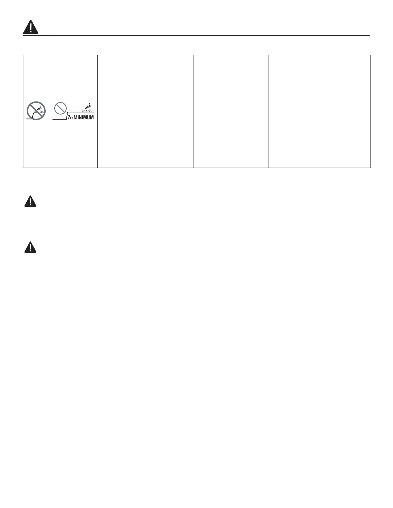
76
Manténgase al menos a
dos anchos de corte (7
pies/2.13 m) de distancia
de zanjas, desniveles
o agua para evitar
accidentes al caer por el
borde o al agua.
INSTRUCCIONES DE SEGURIDAD PARA PODADORAS DE CÉSPED
PELIGRO:
• Esta máquina puede amputar extremidades y arrojar objetos. El incumplimiento de las siguientes
instrucciones de seguridad podría provocar lesiones graves o la muerte.
ADVERTENCIA:
• No exponga la podadora al fuego o a una temperatura excesiva. La exposición al fuego o a
temperaturas por encima de los 130 °C (265 °F) podría causar una explosión.
Información general
• Lea, comprenda y siga las instrucciones y advertencias que se encuentran tanto en este manual
como en la máquina y en los accesorios.
• Solo permita que usen la máquina personas que sean responsables, estén capacitadas y
familiarizadas con las instrucciones y sean físicamente aptas para operarla.
• No transporte pasajeros y mantenga alejados a los transeúntes.
• No use la podadora bajo los efectos del alcohol o las drogas.
• Siga las recomendaciones del fabricante en cuanto a pesos o contrapesos de las ruedas.
Preparación antes de la operación
• Limpie el área de trabajo y retire cualquier objeto que pudiera salir despedido o que interera en el
funcionamiento de la máquina.
• Mantenga a los transeúntes, especialmente a los niños pequeños, alejados del área de operación.
Detenga la máquina y los accesorios si alguien se acerca al área.
• No use la podadora si el colector de césped completo, el conducto de descarga u otros dispositivos
de seguridad no se encuentran en su lugar y en perfecto funcionamiento. Verique con frecuencia
si hay signos de desgaste o deterioro, y reemplace las piezas según sea necesario.
INFORMACIÓN DE SEGURIDAD

77
INFORMACIÓN DE SEGURIDAD
• Utilice equipo de protección personal adecuado, como gafas de seguridad, auriculares de
seguridad y calzado.
Funcionamiento
• Use la máquina únicamente a la luz del día o con una buena luz articial.
• Evite los oricios, surcos, protuberancias, piedras u otros peligros ocultos. Los terrenos desparejos
pueden causar que la máquina se dé vuelta o que el operador pierda el equilibrio o la posición.
• No ponga las manos ni los pies cerca de las piezas giratorias o debajo de la máquina. Manténgase
alejado de la abertura de descarga en todo momento.
• No dirija el material de descarga hacia nadie. Evite descargar material contra una pared o una
obstrucción. El material puede rebotar hacia el operador. Detenga las cuchillas al cruzar supercies
de gravilla.
• No deje una máquina funcionando sin supervisión. Estacione la unidad siempre en un terreno
nivelado, desenganche el accesorio, ponga el freno de mano y detenga el motor.
• No corte en reversa, a menos que sea absolutamente necesario. Siempre mire hacia abajo y hacia
atrás antes de retroceder.
• Evite cortar el césped mojado. Cortar en supercies mojadas puede provocar la pérdida de control
y que las ruedas se hundan en el césped blando.
• Si se presenta alguna situación que no aparece en este manual, tenga cuidado y aplique su
criterio. Póngase en contacto con el Servicio al Cliente de Kobalt para obtener ayuda.
Especicaciones para niños
• Pueden ocurrir accidentes trágicos si el operador no está alerta de la presencia de los niños.
Generalmente, a los niños les atrae esta máquina y el proceso de podado. Nunca suponga que los
niños permanecerán donde los vio por última vez.
• Mantenga a los niños fuera del área de trabajo y bajo la estricta vigilancia de un adulto responsable
que no sea el operador.
• No transporte niños, incluso con las cuchillas retiradas. Los niños podrían caerse y sufrir lesiones
graves o interferir con el funcionamiento seguro de la máquina. Los niños a los que se les ha dado
paseos en el pasado podrían aparecer repentinamente en el área de corte para dar otro paseo y
ser víctimas de atropello por la máquina.
Especicaciones sobre la pendiente
ADVERTENCIA: Las pendientes son un factor importante relacionado con los accidentes. El
funcionamiento en pendientes requiere precauciones adicionales.
• Muévase en la dirección recomendada por el fabricante en las pendientes. Tenga cuidado al operar
cerca de desniveles.
• No use la máquina bajo ninguna circunstancia si duda del funcionamiento de la tracción, la dirección
o la estabilidad, ya que los neumáticos se pueden deslizar aun si las ruedas están detenidas.
• Siempre mantenga la máquina en marcha cuando descienda por las pendientes. No descienda por
inercia.

78
INFORMACIÓN DE SEGURIDAD
• Evite arrancar y detenerse en pendientes. Evite realizar cambios bruscos de velocidad o dirección.
Realice los cambios de manera suave y gradual.
• Tenga especial cuidado al operar la máquina con un colector de césped u otros accesorios. Pueden
afectar la estabilidad de la máquina.
Para transportar
• Utilice rampas de ancho adecuado para cargar y descargar una máquina para su transporte.
Transporte
• La máquina es pesada y puede provocar graves lesiones por aplastamiento. Tenga mucho cuidado
al cargarla o descargarla de un vehículo o remolque.
• Utilice rampas de ancho adecuado para cargar la máquina en un remolque o camión.
• Utilice un remolque aprobado para transportar la máquina. Conecte el freno de mano eléctrico
al soltar el pedal del acelerador y, con la palanca de bloqueo del freno de mano levantada, pise
a fondo el pedal del freno para conectarlo. Sujete la máquina con dispositivos aprobados, como
correas, cadenas o cintas.
• Se deben usar correas de amarre delanteras y traseras dirigidas hacia abajo y hacia afuera de la
máquina.
PELIGRO: Tenga mucha precaución al cargar la máquina en un camión o remolque con rampas.
Existe la posibilidad de sufrir lesiones graves o la muerte si la máquina se cae de las rampas.
ADVERTENCIA: El freno de mano no es suciente para bloquear la máquina en su lugar durante
el transporte. Asegúrese de que la máquina esté bien sujeta al vehículo de transporte. Coloque
siempre la máquina en reversa sobre el vehículo de transporte para evitar que se vuelque.
• No opere esta máquina en vías públicas.
• Compruebe y respete las normas de tráco locales antes de transportar la máquina por carretera.
• No remolque esta máquina; podría causar daños al sistema de accionamiento.
• Para reducir el riesgo de lesiones y daños materiales, NUNCA suba o baje la máquina por la
rampa. ¡No la levante! La máquina no está diseñada para levantarse manualmente.
• Al cargar o descargar esta máquina, no utilice más del ángulo de operación máximo recomendado
de 15 grados.
Remolque
• No remolque un carro que exceda los 272 kg (600 libras) de peso total rodante. El peso del
carrito y otras especicaciones se incluyen en el manual del propietario suministrado con su carrito.
• Conecte el carrito únicamente al enganche. Riesgo de lesiones personales o daños materiales.
• Nunca permita que niños u otras personas entren o suban al carrito. Riesgo de lesiones
personales.
• No remolque en pendientes. El peso del carrito remolcado puede causar pérdida de tracción,
pérdida de control y de la capacidad de detenerse al remolcar en una supercie inclinada.

79
INFORMACIÓN DE SEGURIDAD
• Tenga siempre especial cuidado al remolcar su podadora. Haga giros amplios para evitar
doblarse. Use con cuidado cuando se mueva en reversa.
• Conduzca a baja velocidad y deje una distancia adicional para detenerse.
• No remolque cerca de zanjas, canales y otros peligros. Existe riesgo de pérdida de tracción o
control.
• Siga todas las advertencias e instrucciones proporcionadas por el fabricante del carrito.
El incumplimiento de todas estas instrucciones puede causar lesiones personales o daños a la
propiedad.
• Siga las recomendaciones del fabricante sobre los límites de peso para equipos de remolque
y sobre el remolque de cargas en pendientes.
Reparación
ADVERTENCIA: Los componentes de la bolsa para césped, el conducto de descarga lateral
y el tapón para compuesto orgánico pueden desgastarse y dañarse, lo que puede dejar expuestas
las piezas móviles y permitir que se arrojen objetos y que aumente el riesgo de lesiones. Para una
protección de seguridad, verique frecuentemente todos los componentes y reemplace los dañados
de inmediato con piezas de repuesto idénticas, incluidas en este manual.
• Mantenga la máquina en buen estado de funcionamiento. Reemplace las piezas desgastadas o
dañadas. Compruebe de forma periódica el motor y los frenos.
• Tenga cuidado al dar mantenimiento a las cuchillas. Envuelva las cuchillas o use guantes.
Reemplace las cuchillas dañadas. No repare ni modique las cuchillas.
• Detenga siempre el motor y retire la llave de seguridad antes de realizar tareas de mantenimiento,
limpieza o extracción de material de la podadora de césped.
• Después de golpear un objeto extraño, detenga el motor, retire la llave de seguridad, espere a que
las cuchillas dejen de girar e inspeccione minuciosamente la podadora de césped en busca de
daños. Repare los daños antes de usar la podadora de césped.
• Permita que solo una persona capacitada repare la podadora de césped, mediante el uso solo de
piezas de repuesto idénticas. Esto mantendrá la seguridad de la podadora de césped.
• Siga las instrucciones para reemplazar accesorios.
• Mantenga la podadora de césped libre de acumulación de grasa, suciedad y otros materiales
posiblemente combustibles.
• Mantenga tuercas, pernos y tornillos ajustados para asegurarse de que la podadora se encuentra
en una condición de trabajo segura.
• Nunca retire o manipule los dispositivos de seguridad. Verique con regularidad que funcione
correctamente. Nunca haga algo para interferir con la función para la que fue diseñado el
dispositivo de seguridad o para disminuir la protección que proporciona el dispositivo de seguridad.
• Conserve o reemplace las etiquetas de seguridad o de instrucciones según sea necesario.
• Recargue el paquete de baterías solo con el cargador especicado por el fabricante. Un cargador
adecuado para un tipo de paquete de baterías puede suponer un riesgo de incendio cuando se usa
con otro paquete de baterías diferente.
• No cargue la podadora bajo la lluvia o en lugares mojados.
• No utilice la podadora a batería bajo la lluvia.

80
INFORMACIÓN DE SEGURIDAD
• No lave la podadora de césped con una manguera; evite que ingrese agua al motor y a las
conexiones eléctricas.
• Almacene la podadora en interiores. Cuando no esté en uso, se debe almacenar en un lugar seco,
en interiores y fuera del alcance de los niños.
Advertencias adicionales
• El paquete de baterías está integrado con el producto y no se debe retirar.
• Utilícelo solo con el cargador de baterías KOBALT KRC 752-03.
• El manual del cargador se suministra por separado e incluye normas de seguridad especícas e
instrucciones de funcionamiento. Consulte el manual del cargador para conocer las normas de
seguridad y las instrucciones de funcionamiento detalladas.
Declaración de la FCC
a Este dispositivo cumple con la sección 15 de las reglas de la FCC. El funcionamiento está sujeto a las
siguientes dos condiciones:
a) Este dispositivo no debe causar interferencia perjudicial.
b) Este dispositivo deberá aceptar cualquier interferencia recibida, inclusive la interferencia que
pudiese causar la operación no deseada.
b Los cambios o las modicaciones que no estén expresamente aprobados por la parte responsable
del cumplimiento podrían anular la autorización del usuario para utilizar el equipo.
AVISO: Este equipo se probó y se vericó su cumplimiento con los límites para un dispositivo digital
de clase B, conforme a la sección 15 de las reglas de la Comisión Federal de Comunicaciones (FCC,
por sus siglas en inglés). Estos límites están diseñados para proporcionar protección razonable
contra interferencias perjudiciales en una instalación residencial. Este equipo genera, utiliza y puede
irradiar energía de radiofrecuencia y, si no se instala y usa según las instrucciones, puede causar
interferencias perjudiciales para las comunicaciones de radio. Sin embargo, no se garantiza que
no se producirán interferencias en una instalación en especial. Si este equipo causa interferencia
perjudicial a la recepción de radio o televisión, lo que se puede determinar al encender y apagar el
equipo, se recomienda al usuario que intente corregir la interferencia con una o más de las siguientes
medidas: reorientar o reubicar la antena de recepción. Aumentar la separación entre el equipo y el
recibidor. Conectar el equipo a un tomacorriente de un circuito distinto al que usa el receptor. Solicitar
ayuda al distribuidor o a un técnico con experiencia en radio/TV.

81
PREPARACIÓN
Conozca su podadora de césped
Su podadora se diseñó para los nes que se enumeran a continuación:
• Cortar su césped
Antes de comenzar a ensamblar el producto, asegúrese de tener todas las piezas. Compare las
piezas con la lista del contenido del paquete y la lista de aditamentos. No intente ensamblar el
producto si falta alguna pieza o si alguna está dañada.
Herramientas necesarias para desembalar:
• Tijeras o tijeras de corte lateral (no incluidos)
• Dos llaves inglesas combinadas (incluidas)
Herramientas necesarias para el montaje y el ajuste:
• Dos llaves inglesas combinadas (incluidas)
• Una llave de tuerca de 18 mm (incluida)
ADVERTENCIA:
• Sea cuidadoso, incluso si está familiarizado con la herramienta. Recuerde que tan solo un
momento de descuido es suciente para causar lesiones graves.
• Antes de intentar utilizar cualquier máquina, asegúrese de familiarizarse con todas las
características de funcionamiento e instrucciones de seguridad.
• No intente modicar esta máquina ni crear accesorios que no sean recomendados para utilizar con
la misma. Toda alteración o modicación se considera un uso indebido y podría dar lugar a una
situación peligrosa que resulte en lesiones graves.
1. Desembalaje
ADVERTENCIA:
• Para reducir el riesgo de lesiones o daños a la podadora, no utilice un cuchillo para cortar las
correas de nailon. Use tijeras o tijeras de corte lateral.
ADVERTENCIA:
• Para reducir el riesgo de daños, quítese los relojes u otros objetos frágiles y valiosos de sus
muñecas. Existe riesgo de contacto accidental con elementos de estructura de acero.
a. Retire la cubierta de plástico de la estructura y la cubierta de papel de la parte superior de la
estructura.
b. Utilice los extremos de 13 mm de las llaves inglesas combinadas (HH) para quitar los 18 pernos que
sujetan la estructura (Fig. 1a) y, luego, retire el marco.
NOTA: Para simplicar y acelerar el proceso, utilice una llave de percusión con un casquillo de 13
mm (1/2 pulg.) (no incluida).
c. Abra la tapa del compartimiento de almacenamiento, saque el volante, los accesorios y el manual.
d. Corte las correas de nailon, retire la caja del cargador y el asiento.

82
PREPARACIÓN
13 15
13 15
13 15
x2
x2
x1
x2
x1
x1
x2
x1
1a
HH
Asiento
Cargador
e. Retire y deje a un lado todos los embalajes y materiales de embalaje accesibles. No se deshaga del
material de embalaje hasta que haya inspeccionado con cuidado y utilizado satisfactoriamente el
producto.
f. Si hay disponible una rampa adecuada de ancho completo, colóquela contra el marco inferior, cerca
de las ruedas delanteras. No exceda el ángulo de funcionamiento máximo recomendado de 15°. La
podadora se puede retirar del marco sin rampa. Dos piezas de madera de 2x4 ayudan a reducir la
“caída” desde el marco inferior hasta el suelo.
g. Presione el pedal del freno de mano (K) para liberarlo de la posición del freno de mano. Se requiere
un esfuerzo considerable para soltar el pedal del freno de mano con la mano. ¡Empuje con fuerza!
PRECAUCIÓN: Objeto pesado. Se requiere empuje en equipo. Se necesitan al menos dos
personas para empujar esta podadora fuera del marco de acero.
h. Sujete las esquinas traseras y las áreas alrededor del asiento de la podadora simultáneamente en
ambos lados y empuje despacio la podadora fuera del marco de acero en dirección hacia adelante
(Fig. 1b).
AVISO: EMPUJE LA PODADORA SOLO HACIA ADELANTE. Tirar de la podadora hacia atrás
desde el marco de acero puede causar daños a la plataforma de corte de la podadora. ¡Retire
siempre la podadora del marco en dirección hacia delante!
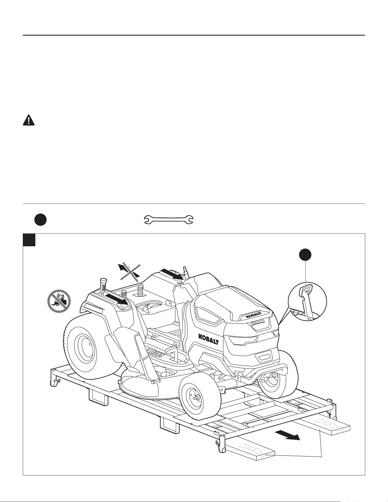
83
PREPARACIÓN
AVISO: ¡La podadora debe transportarse en todo momento sobre el marco inferior! ¡El
montacargas nunca debe entrar en contacto directo con la podadora! Hacerlo podría causar daños.
Recomendamos conservar el marco inferior para facilitar el transporte posterior de la podadora para
su mantenimiento.
i. Corte la correa de nailon que sujeta el conducto de descarga lateral una vez que la podadora esté
en el suelo.
PRECAUCIÓN: Si, luego de desembalar el producto, nota que ya tiene algunas piezas de la lista
de empaque ensambladas, no lo use. El fabricante no vende el producto con las piezas de la lista
de empaque ensambladas. El cliente debe hacerlo. Si se usa un producto con piezas ensambladas
incorrectamente, se pueden producir lesiones personales graves.
• Inspeccione el producto para asegurarse de que no se produjo ninguna ruptura o daño durante el
envío.
• Si alguna pieza está dañada o falta, póngase en contacto con el Servicio al Cliente de Kobalt.
Aditamentos utilizados
HH
Llave de combinación
13 15
x 2
1b
K
(en posición
liberada)
2x4
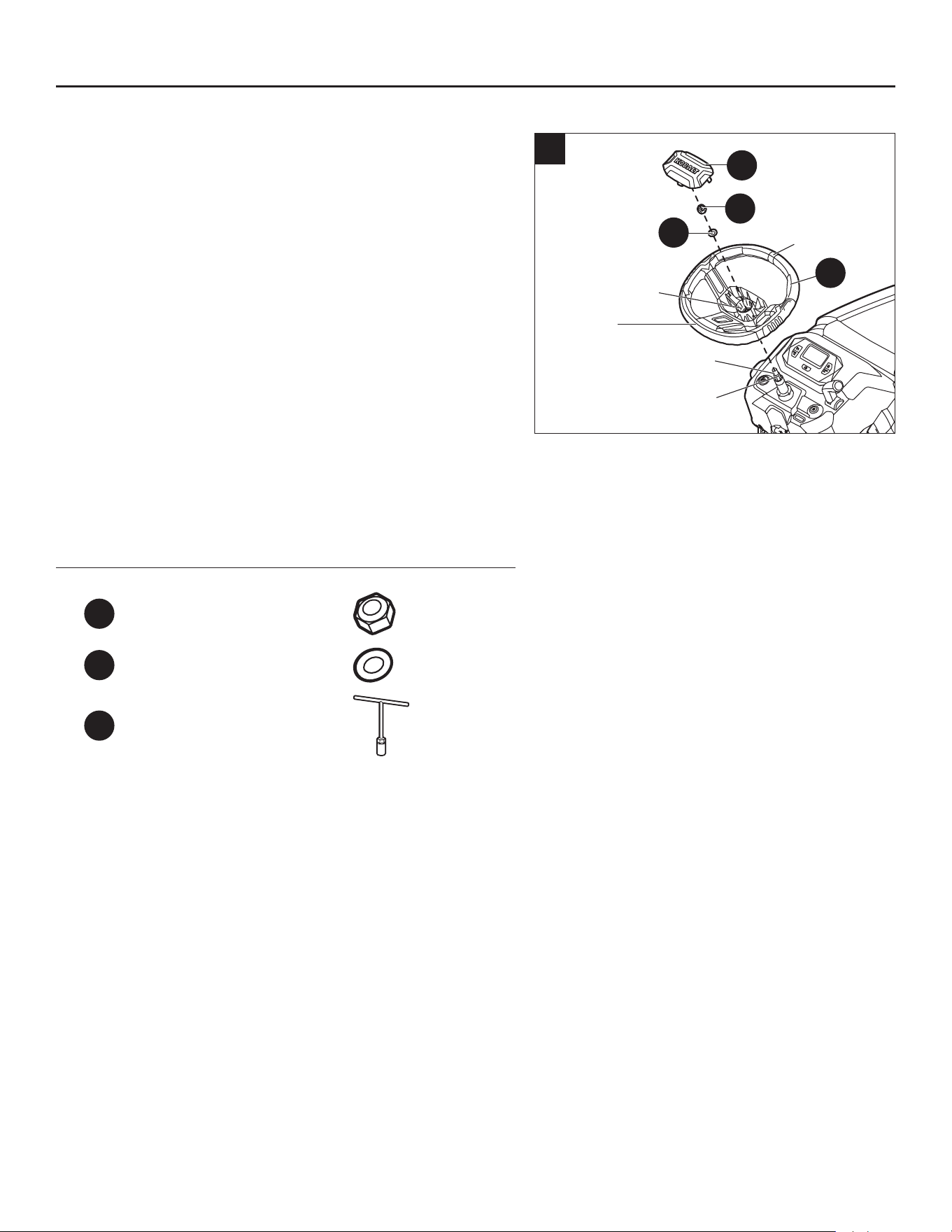
84
INSTRUCCIONES DE ENSAMBLAJE
2. Instalación del volante
a. Retire la arandela (BB) y la tuerca M12 (AA) de la
bolsa de accesorios y déjelas a un lado.
b. Con las ruedas delanteras de la podadora apuntando
hacia adelante, monte el volante (V) en la columna
de dirección manteniendo la línea central apuntando
hacia adelante y la sección plana mirando hacia el
asiento.
c. Gire un poco el volante (V) hasta que la ranura del
engranaje del oricio de montaje quede alineada con
el engranaje de la columna de dirección.
d. Monte la arandela (BB) y la tuerca (AA). Apriételas
rmemente con la llave de tuerca de 18 mm (GG). El
par recomendado es de 29.5 a 33.2 pies-libras. (40-
45 Nm).
e. Coloque correctamente la tapa antipolvo (W) en el
volante (V).
Aditamentos utilizados
AA
Tuerca M12 x 1
BB
Arandela x 1
GG
Llave de tuerca de 18
mm
x 1
2
Ranura para
engranajes
Columna de
dirección
Línea
central
Engranaje
Sección
plana
BB
AA
W
V
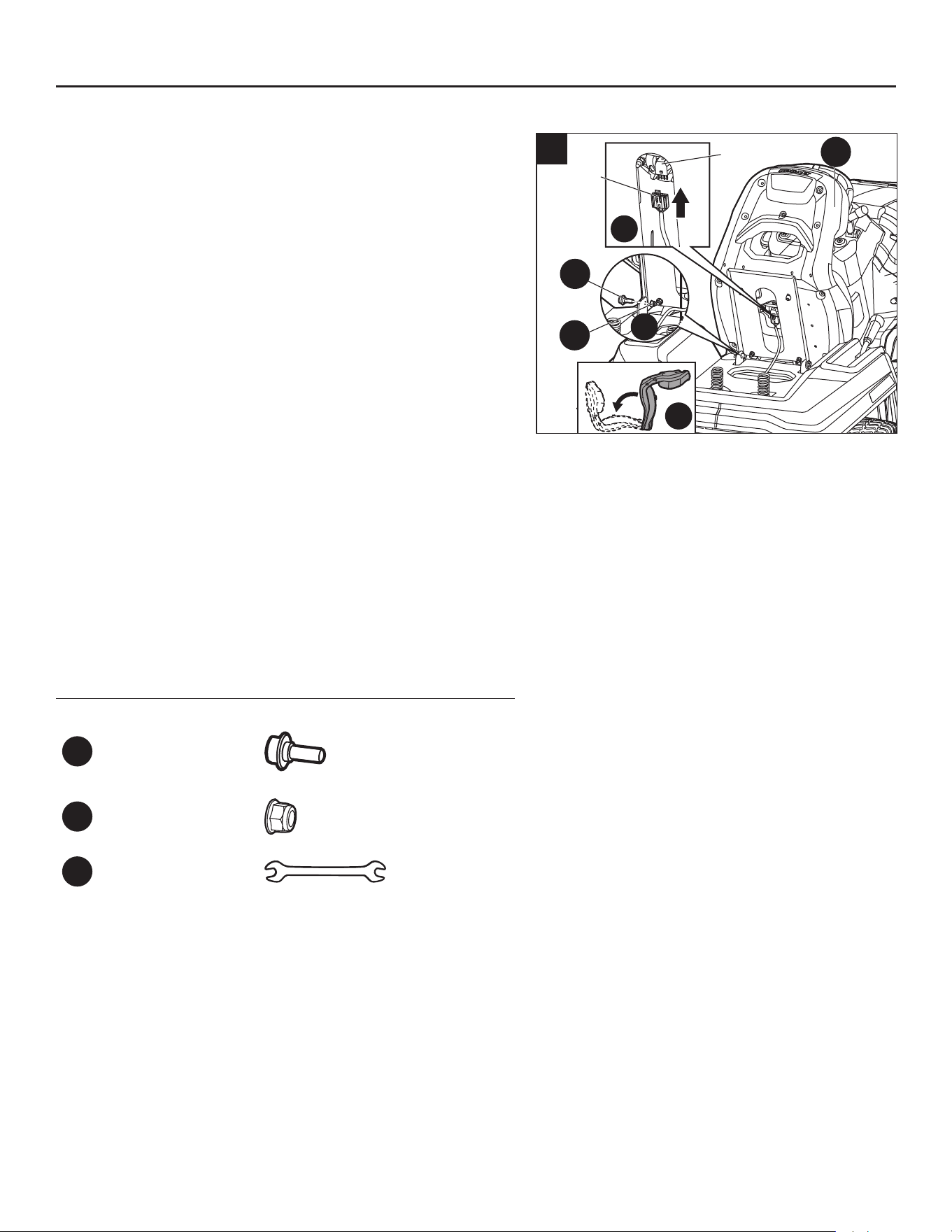
85
3. Instalación del asiento
La podadora incorpora un sistema de bloqueo de
seguridad que detendrá los motores de accionamiento
y los motores de las cuchillas cuando el operador
se levanta del asiento por cualquier motivo mientras
la podadora está en funcionamiento. Esta es una
característica de seguridad diseñada para evitar que se
salga de control o se enrede accidentalmente.
a. Retire los dos juegos de perno escalonado (CC) y
tuerca M8 (DD) de la bolsa de accesorios y déjelos a
un lado.
b. Coloque el asiento (X) sobre su frente y alinee los
dos oricios de montaje con los oricios de la base de
suspensión.
c. Inserte los dos juegos de pernos (CC) y tuercas
(DD) y apriételos rmemente con las llaves inglesas
combinadas (HH). El par recomendado es de 13.3 a
14.8 pies-libras. (18–20 Nm).
d. Inserte el enchufe del cable en el enchufe situado en
la parte inferior del asiento. Esto conecta el sistema
de bloqueo de seguridad.
e. Gire el asiento para colocarlo sobre la base de
suspensión.
Aditamentos utilizados
CC
Perno
de cuello
cuadrado
x 2
DD
Tuerca M8 x 2
HH
Llave de
combinación
13 15
x 2
INSTRUCCIONES DE ENSAMBLAJE
2
1
3
3
Enchufe
de cable
Dado
CC
X
DD
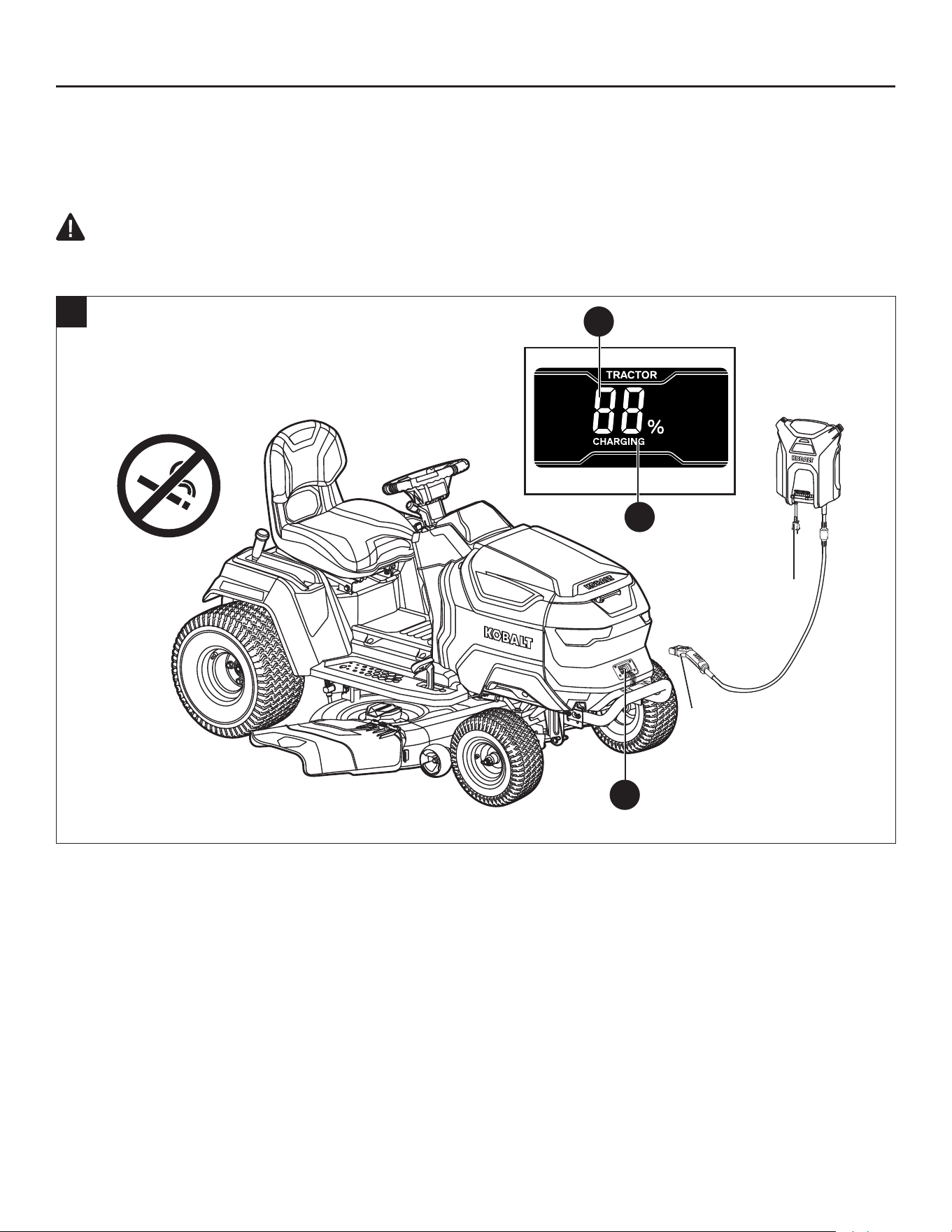
86
INSTRUCCIONES DE ENSAMBLAJE
4. Cargar la podadora
Cargue la podadora antes de usarla por primera vez.
AVISO: El paquete de baterías está integrado con el producto y no se debe retirar.
PRECAUCIÓN: NO intente cargar el cortacésped con un cargador que no esté diseñado
para usarse con este producto.
Utilice únicamente el cargador de baterías KOBALT KRC 752-03 para cargar la podadora.
4a
Enchufe y cable
de alimentación
Cable y enchufe
de carga
q
p
J
a. Asegúrese de que la podadora se detenga por completo, apáguela, ponga el freno de mano y retire
la llave de seguridad (EE).
b. Levante la tapa antipolvo del puerto de carga de la batería (J) de la podadora, retire la tapa de goma
y conecte el enchufe al puerto de carga.
NOTA: El enchufe solo encajará de una manera en el puerto. Asegúrese de que esté correctamente
alineado antes de insertarlo.
c. Enchufe el cable de alimentación del cargador a una toma doméstica estándar de 120 V.
d. El cargador comenzará a cargar la batería. El indicador de audio emitirá un pitido, el ícono
“CARGANDO” (p) se iluminará en la pantalla LCD (A1) y el indicador de combustible (q) mostrará el
nivel de carga.
e. Tan pronto como la batería esté completamente cargada, el indicador de combustible (q) mostrará “100
%” y el ícono “CARGANDO” (p) desaparecerá de la pantalla LCD (A1). Desconecte el enchufe del cable
de alimentación del tomacorriente de pared y retire el enchufe de carga del puerto de carga (J).
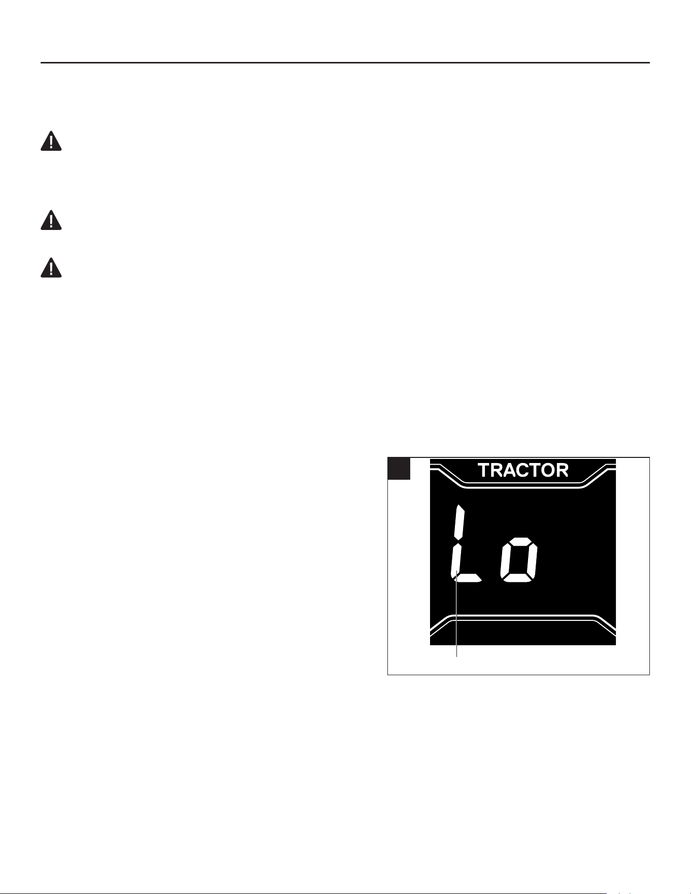
87
INSTRUCCIONES DE ENSAMBLAJE
f. Coloque la cubierta de goma y asegúrese de que el puerto de carga (J) esté cubierto adecuadamente
por la tapa antipolvo para proteger el puerto de carga del agua, la humedad o el polvo.
ADVERTENCIA:
• Consulte el manual incluido con el cargador para obtener instrucciones detalladas. Lea
y comprenda todas las advertencias de seguridad y las instrucciones. No seguirlas podría
provocar descargas eléctricas, incendio o lesiones personales graves.
ADVERTENCIA:
• No fume mientras carga la podadora.
ADVERTENCIA:
• La podadora de césped debe cargarse en un área cubierta, protegida de la lluvia o en el interior.
NOTA:
• La batería no desarrolla memoria y no es necesario descargarla completamente antes de
recargarla.
• Cada seis meses de almacenamiento a largo plazo, cargue completamente la batería para obtener
la mayor duración posible.
• Al cargar, asegúrese de que la entrada y salida del ventilador de refrigeración del cargador no
estén bloqueadas.
Modo de bajo consumo
Cuando la carga de la batería llega a un nivel muy bajo,
la podadora entrará en modo de bajo consumo para
conservar suciente energía para regresar al área de
carga:
• Las cuchillas cambiarán a una velocidad de rotación
baja, lo que solo podrá cortar una cantidad muy
pequeña de césped. Al encontrar césped alto y denso,
las cuchillas dejarán de girar. El indicador de audio
sonará (bip) de forma intermitente. La luz del botón de
encendido/apagado de la cuchilla (G1) parpadeará.
El ícono de “cuchilla encendida” (f) parpadeará en la
pantalla LCD (A1).
• El indicador de combustible (q) será reemplazado por un mensaje de batería baja parpadeante en
la pantalla LCD.
El operador debe hacer lo siguiente:
• Presione el botón de encendido/apagado de las cuchillas (G1) para apagar los motores de las
cuchillas. El indicador de audio dejará de sonar, la luz del botón de encendido/apagado de la
cuchilla se apagará y el ícono de “hoja encendida” (f) desaparecerá de la pantalla LCD cuando los
motores de las cuchillas se detengan.
4b
Mensaje de batería baja
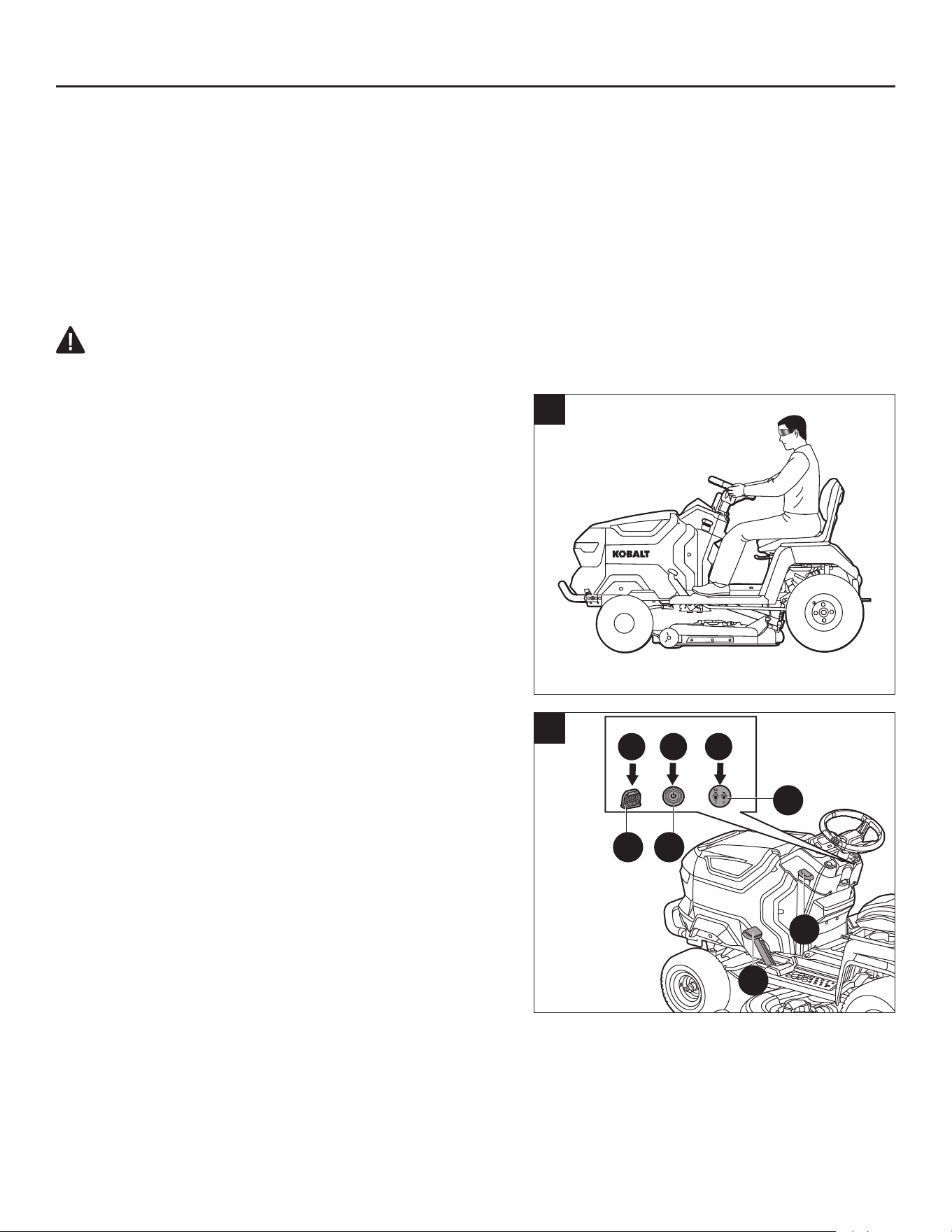
88
INSTRUCCIONES DE ENSAMBLAJE
• Deje de trabajar y diríjase a la zona de carga lo antes posible. La distancia máxima que puede
recorrer la podadora es de aprox. 0.96 kilómetros (0.6 millas).
Cuando la batería esté casi agotada, la podadora dejará de funcionar inmediatamente. El operador
deberá transportar la podadora a la zona de carga para cargarla.
AVISO: Si es necesario empujar de forma manual, asegúrese de que la podadora esté
completamente apagada, que se haya quitado la llave de seguridad (EE) y que el pedal del freno de
mano (K) esté liberado de la posición del freno de mano.
ADVERTENCIA:
• No intente cruzar carreteras o vías de ferrocarril cuando el nivel de carga de la batería sea bajo.
5. Prueba del sistema de bloqueo de seguridad
Inspeccione el producto para vericar que no haya
piezas dañadas, faltantes o ojas, como tornillos,
tuercas, pernos, tapas, etc. Apriete bien todos los
sujetadores y las tapas, y no use el producto hasta que
se hayan reemplazado las piezas faltantes o dañadas.
La podadora incorpora un sistema de bloqueo de
seguridad que detendrá el motor de accionamiento y los
motores de las cuchillas cuando el operador se levanta
del asiento por cualquier motivo mientras la podadora
está en funcionamiento. Esta es una característica de
seguridad diseñada para evitar que se salga de control
o se enrede accidentalmente. Pruebe el sistema para
asegurarse de que esté funcionando de forma correcta.
Para probar el funcionamiento de las cuchillas
a. Estacione la podadora en una supercie nivelada.
b. Siéntese en el asiento de la podadora (Fig. 5a).
c. Introduzca la llave de seguridad (EE) en la podadora.
Presione el botón de arranque/apagado (E1) durante
más de 3 segundos para iluminar la pantalla LCD. La
pantalla LCD se iluminará indicando que la podadora
está lista para funcionar.
NOTA: Si el pedal del freno de mano (K) está
desacoplado de la posición de freno de mano, debe
presionar completamente el pedal del freno de mano (K)
con el pie y presionar el botón de arranque/apagado (E1)
durante más de 3 segundos de forma simultánea.
d. Presione el botón de encendido/apagado de la cuchilla (G1) durante más de 3 segundos para
encender los motores de las cuchillas (Fig. 5b) y, luego, suelte el botón de encendido/apagado de la
cuchilla.
e. Levántese lentamente del asiento, pero no se baje de la podadora. Los motores de las cuchillas
deberían detenerse.
5a
>3s
>3s
1 2 3
5b
EE E1
G1
M
K
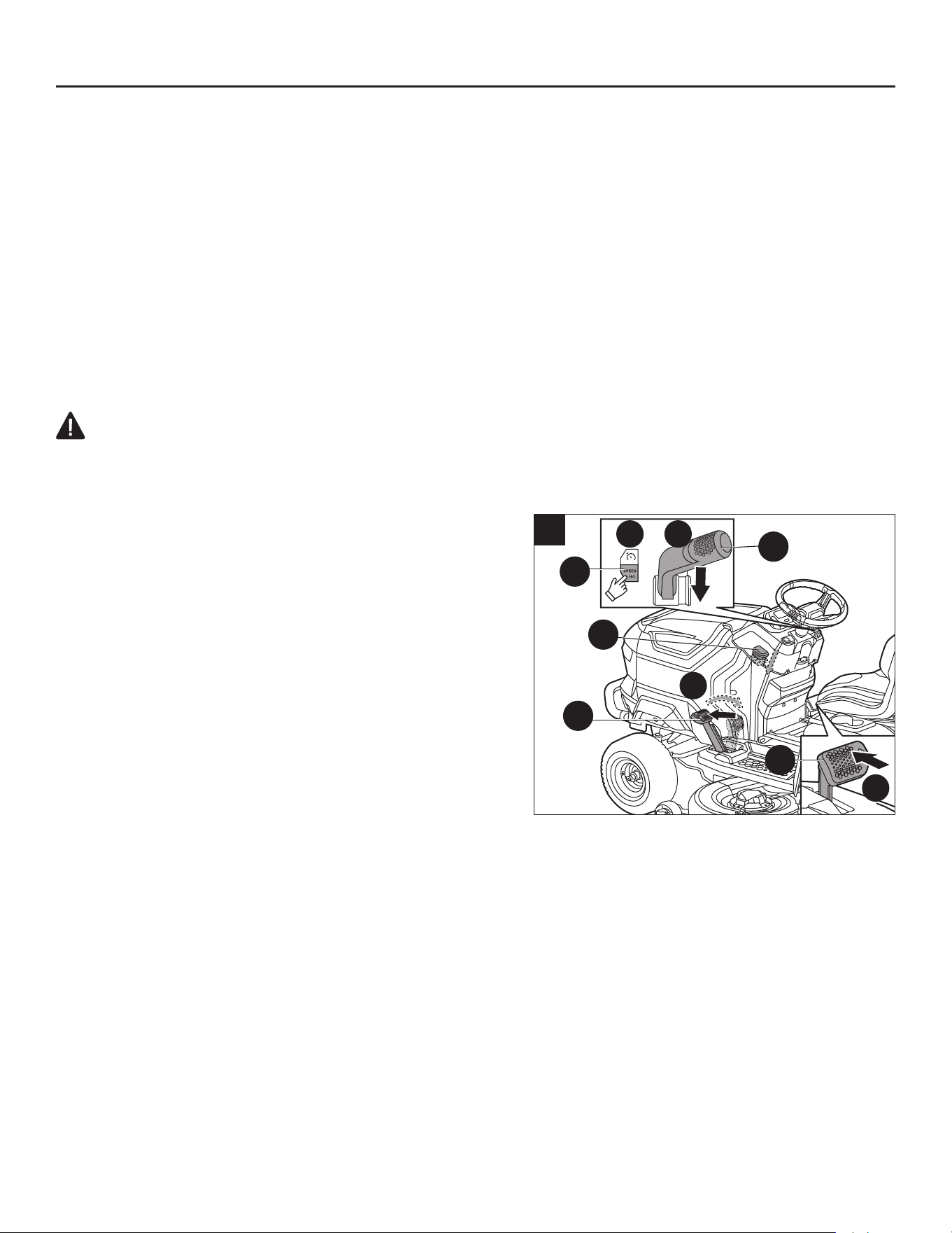
89
INSTRUCCIONES DE ENSAMBLAJE
AVISO:
Si el sistema de cuchillas de la plataforma no se detiene cuando el operador está fuera del
asiento:
a. Presione el botón de encendido/apagado de las cuchillas (G1) de nuevo para apagar los motores de
las cuchillas.
b. Con la palanca de bloqueo del freno de mano (M) abierta, presione completamente el pedal del
freno de mano (K) para activarlo.
c. Retire la llave de seguridad (EE).
d. Levante el respaldo del asiento y verique que la toma y el enchufe estén conectados correctamente.
Consulte el paso “d” en el capítulo “Instalación del asiento”.
Si no se puede determinar la causa después de conrmar que el enchufe y la toma están conectados
de forma correcta, comuníquese con el Servicio al Cliente de Kobalt de inmediato.
ADVERTENCIA:
• NO use la podadora hasta que un técnico de servicio calicado haya reparado el sistema de
bloqueo de seguridad.
Para probar la podadora
a. Mientras todavía está sentado en la podadora,
asegúrese de que esté encendida (la pantalla LCD
está iluminada) y (si está activado) desactive el
freno de mano presionando completamente el pedal
del freno de mano (K) hasta que baje la palanca de
bloqueo del freno (M).
b. Presione el botón de ajuste de la velocidad de
conducción (I1) para ajustar la velocidad de conducción
al nivel bajo.
c. Tire de la palanca de control de dirección (D1) hacia
atrás en la dirección “D” para avanzar.
d. Presione el pedal del acelerador (Q) para conducir la
podadora (Fig. 5c).
NOTA: Si la podadora no se mueve, el ícono del freno de mano (d) parpadeará en la pantalla LCD,
lo que indica que debe presionar completamente el pedal del freno (K), soltarlo y, luego, presionar el
pedal del acelerador (Q) para conducir la podadora.
e. Mientras la podadora está en movimiento, levántese lentamente del asiento. El sistema de conducción
debería detener la podadora.
AVISO: Si el sistema de conducción no se detiene cuando el operador está fuera del asiento:
a. Suelte el pedal del acelerador (Q) para detener la podadora.
b. Con la palanca de bloqueo del freno de mano (M) abierta, presione completamente el pedal del
freno de mano (K) para activarlo.
c. Retire la llave de seguridad (EE).
d. Levante el respaldo del asiento y verique que la toma y el enchufe estén conectados correctamente.
Consulte el paso “d” en el capítulo “Instalación del asiento”.
2 3
1
4
5c
I1
D1
M
K
Q

90
INSTRUCCIONES DE ENSAMBLAJE
Si no se puede determinar la causa después de conrmar que el enchufe y la toma están conectados
de forma correcta, comuníquese con el Servicio al Cliente de Kobalt de inmediato.
ADVERTENCIA:
• NO use la podadora hasta que un técnico de servicio calicado haya reparado el sistema de
bloqueo de seguridad.
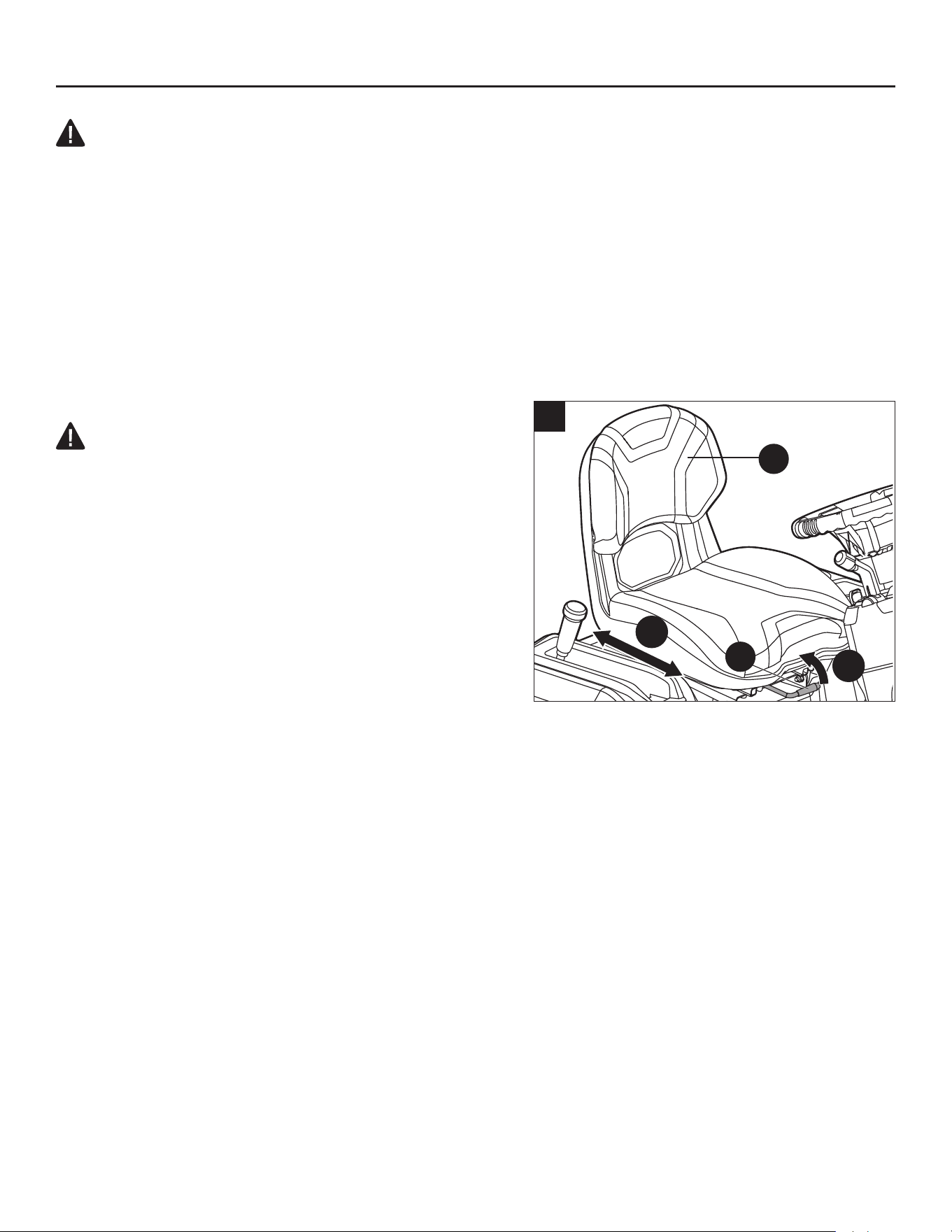
91
INSTRUCCIONES DE FUNCIONAMIENTO
ADVERTENCIA:
• No se descuide por el hecho de conocer el producto. Recuerde que un descuido de una
fracción de segundo es suciente para provocar lesiones graves.
• No utilice ningún acoplamiento o accesorio que el fabricante de este producto no
recomiende. El uso de acoplamientos o accesorios no recomendados puede producir lesiones
personales graves.
• Antes de realizar cualquier ajuste, detenga la podadora en una supercie nivelada y espere
a que las cuchillas se detengan por completo. Con la palanca de bloqueo del freno de mano
(M) abierta, presione completamente el pedal del freno de mano (K) para activarlo y, luego,
retire la llave de seguridad (EE) para evitar un arranque accidental y posibles lesiones
personales graves.
6. Ajuste del asiento
PELIGRO: Asegúrese de que el asiento
esté asegurado a la podadora con los pernos
escalonados antes de operar la podadora. Un asiento
que no esté seguro puede hacer que el operador pierda
el control de la podadora, lo que podría provocar la
muerte o lesiones personales graves.
Ajuste la posición del asiento para asegurarse de que
pueda hacer un contacto rme con el pedal del freno y
del acelerador antes de operar la podadora.
El asiento se puede ajustar hacia adelante y hacia atrás
al girar hacia arriba la palanca de ajuste de la posición
del asiento (Y) debajo del asiento.
a. Gire la palanca de ajuste de la posición del asiento (Y) hacia arriba y manténgala, y, luego, mueva
el asiento (X) hacia adelante o hacia atrás hasta la posición deseada.
b. Suelte la palanca de ajuste de la posición del asiento (Y) y asegúrese de que el asiento (X) esté
bloqueado en su posición.
2
1
6
X
Y
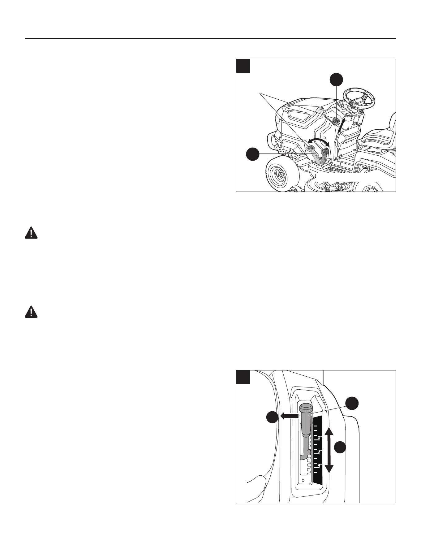
92
INSTRUCCIONES DE FUNCIONAMIENTO
7. Ajuste del freno de mano
El pedal del freno de mano (K) se puede utilizar para
colocar la podadora en la posición de freno de mano.
Para poner en marcha la podadora, debe soltarlo de la
posición del freno de mano.
Para poner el freno de mano:
a. Detenga la podadora en una supercie nivelada.
b. Con la palanca de bloqueo del freno de mano (M)
abierta, presione completamente el pedal del freno
de mano (K) hasta que el pedal deje de rebotar.
c. Suelte la palanca de bloqueo del freno de mano (M).
Retire el pie del pedal del freno de mano (K).
d. Para soltar el freno de mano, pise el pedal del
freno (K) una vez más; el pedal rebotará hasta la posición soltada y la palanca de bloqueo del
freno de mano (M) bajará a la posición soltada.
ADVERTENCIA:
• El pedal del freno de mano no puede reducir la velocidad de conducción. Nunca intente
pisar el pedal del freno para reducir la velocidad durante la conducción. Cuando se pisa el
pedal del freno de mano pero no se pone en la posición de freno de mano, el freno eléctrico
ya no es efectivo y la podadora dejará de moverse en una supercie plana. Pero si esto
sucede en una pendiente, la podadora puede deslizarse cuesta abajo una vez que se suelta
el pedal del freno de mano.
ADVERTENCIA:
• Nunca deje la podadora de césped desatendida durante las pausas de trabajo sin vericar
que el freno de mano esté puesto y que la llave de seguridad (EE) esté retirada. Si no se
aplica el freno de mano, la podadora podría moverse. Dejar la llave de seguridad en su lugar puede
permitir un uso no autorizado que podría provocar lesiones personales graves.
8. Ajuste de la altura de corte
Antes de cortar el césped, la plataforma (E) debe
ajustarse a una altura suciente para evitar tocones,
rocas u otros obstáculos que puedan dañar la
plataforma de la podadora.
a. Sujete la palanca de ajuste de altura de la plataforma
(A) y muévala hacia adentro para desengancharla del
retén.
b. Mueva la palanca (A) hacia adelante para disminuir
la altura de corte o hacia atrás para aumentarla.
Enganche la palanca (A) en el retén cuando llegue a
la altura de corte deseada.
7
Posición del
freno de mano
Posición liberada
M
K
1
2
8
A
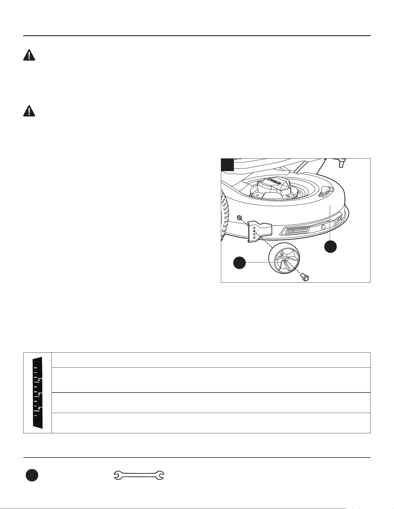
93
INSTRUCCIONES DE FUNCIONAMIENTO
PELIGRO:
• Nunca intente realizar ningún ajuste en la plataforma de corte mientras la podadora está en
marcha o los motores de las cuchillas están encendidos. Las cuchillas de la podadora no se
pueden ver y están ubicadas muy cerca de la carcasa de la plataforma. Los dedos de manos y pies
se pueden cortar instantáneamente.
ADVERTENCIA:
• Sujete con rmeza la palanca de ajuste de altura de la plataforma (A) al ajustar la altura y
suéltela solo cuando esté rmemente enganchada en el retén deseado. Soltar muy rápido la
palanca puede crear un peligro de pellizco o tirón en la mano del operador.
9. Ajuste de las ruedas protectoras
Las ruedas protectoras (G) están diseñadas para
minimizar la posibilidad de desbroce al cortar en terrenos
irregulares y disparejos. Después de congurar la altura
de corte, ajuste las ruedas protectoras para que se
extiendan por debajo de la plataforma pero de modo que
no entren en contacto con el suelo.
Las ruedas antideslizantes se mantienen en su lugar
mediante una tuerca y un perno cada una. Se pueden
colocar en una de cuatro posiciones:
a. Levante la plataforma (E) a la altura de corte deseada.
b. Utilice el extremo de 13 mm de la llave inglesa
combinada (HH) para estabilizar la tuerca primero
y, luego, aoje y retire el perno del otro lado con el extremo de 15 mm de la otra llave inglesa
combinada (HH).
c. Mueva la rueda antideslizante (G) a la posición deseada. Luego, apriete bien el perno y la tuerca. El
par recomendado para los pernos es de 22 a 26 pies-libras. (30-35 Nm).
d. Repita los pasos con la otra rueda antideslizante (G) y asegúrese de que ambas ruedas estén
instaladas en la misma posición.
Posición 1: altura de corte de césped inferior a 51 mm (2 pulg.)
Posición 2: altura de corte de césped de 51 a 76 mm (2 a 3 pulg.)
Posición 3: altura de corte de césped de 76 a 102 mm (3 a 4 pulg.)
Posición 4: altura de corte de césped superior a 102 mm (4 pulg.)
Aditamentos utilizados
HH
Llave de
combinación
13 15
x 2
9
G
E

94
INSTRUCCIONES DE FUNCIONAMIENTO
10. Arranque de la podadora (Fig. 10a)
Lista de vericación antes de arrancar la podadora
• Asegúrese de que el área de trabajo esté libre de niños, transeúntes y mascotas.
• Despeje el área de trabajo de objetos que puedan ser lanzados por las cuchillas del
cortacésped.
• Limpie los residuos de la podadora.
• Compruebe que no haya sujetadores sueltos.
• Asegúrese de que todos los protectores estén en su lugar y funcionando correctamente.
• Compruebe a simple vista si los neumáticos están inados.
• Verique el funcionamiento del freno.
• Ajuste la altura de la plataforma a la posición de corte deseada que mejor se adapte al
césped y ajuste las ruedas protectoras en consecuencia.
• Ajuste la posición del asiento y asegúrese de que se puedan alcanzar ambos pedales.
• Verique el nivel de carga de la batería.
• Pruebe el sistema de bloqueo de seguridad.
Antes de comenzar a cortar el césped, le recomendamos que busque un área grande, nivelada
y abierta para practicar el funcionamiento de la podadora siguiendo las instrucciones que
aparecen a continuación. Una vez que pueda realizar cada una de estas maniobras de manera
cómoda y conable, estará listo para comenzar a cortar el césped.
ADVERTENCIA:
• Despeje el área de transeúntes antes de operar la podadora. Si alguien ingresa al área de
corte, deténgase inmediatamente y no vuelva a cortar hasta que los transeúntes abandonen
el área.
PELIGRO:
• Evite arranques, paradas y giros repentinos, así como la velocidad excesiva, especialmente
cuando está aprendiendo a operar la podadora de césped por primera vez. La podadora
puede girar rápidamente, lo que puede causarle la pérdida de control y provocar la muerte,
lesiones personales graves o daños a la podadora. Presione el botón de ajuste de velocidad
de conducción (I1) para congurar el nivel de velocidad baja para limitar la cantidad de
velocidad disponible hasta que sea completamente capaz de operar la podadora de césped
en todas las situaciones.
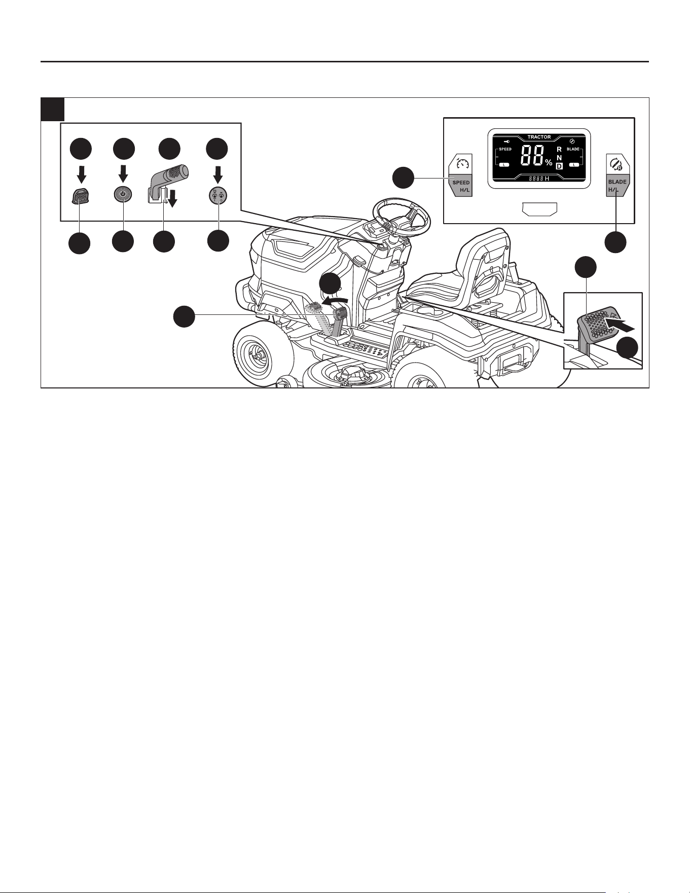
95
INSTRUCCIONES DE FUNCIONAMIENTO
4
>3s
>3s
1 2 3 5
2
4
>3s
10a
EE
E1
I1
C1
Q
D1
G1
K
a. Siéntese en el asiento de la podadora.
b. Inserte la llave de seguridad (EE).
c. Presione completamente el pedal del freno (K) con el pie y, al mismo tiempo, presione el botón de
arranque/apagado (E1) durante más de 3 segundos para iluminar la pantalla LCD.
NOTA: Si el pedal del freno de mano (K) está en la posición de freno de mano, solo puede
presionar el botón de arranque/apagado (E1) durante más de 3 segundos para iluminar la pantalla
LCD y, luego, soltar el pedal del freno de mano (K) antes de conducir la podadora.
d. Congure la velocidad de conducción y la velocidad de las cuchillas apropiadas al presionar el botón
de ajuste de la velocidad de conducción (I1) y el botón de ajuste de la velocidad de las cuchillas (C1)
respectivamente.
NOTA: Siempre se recomienda arrancar la podadora a baja velocidad.
e. Presione el pedal del acelerador (Q) para conducir la podadora:
Para avanzar: tire de la palanca de control de dirección (D1) hacia atrás en la dirección “D”.
Para retroceder: empuje la palanca de control de dirección (D1) hacia delante en la dirección “R”.
NOTA: Cuando abandone el asiento y, luego, se vuelva a sentar, la podadora no se moverá después
de presionar el pedal del acelerador (Q) y el ícono del freno de mano parpadeará en la pantalla LCD.
En este caso, debe presionar a fondo el pedal del freno de mano (K), luego soltarlo y presionar el
pedal del acelerador (Q) para conducir la podadora.
f. Presione el botón de encendido/apagado de la cuchilla (G1) durante más de 3 segundos para poner
en marcha las cuchillas de corte y, a continuación, suelte el botón de encendido/apagado de las
cuchillas. El botón mismo se iluminará.
NOTA: Por razones de seguridad, las cuchillas se apagarán al presionar el botón de encendido/
apagado de las cuchillas durante más de 8 segundos.
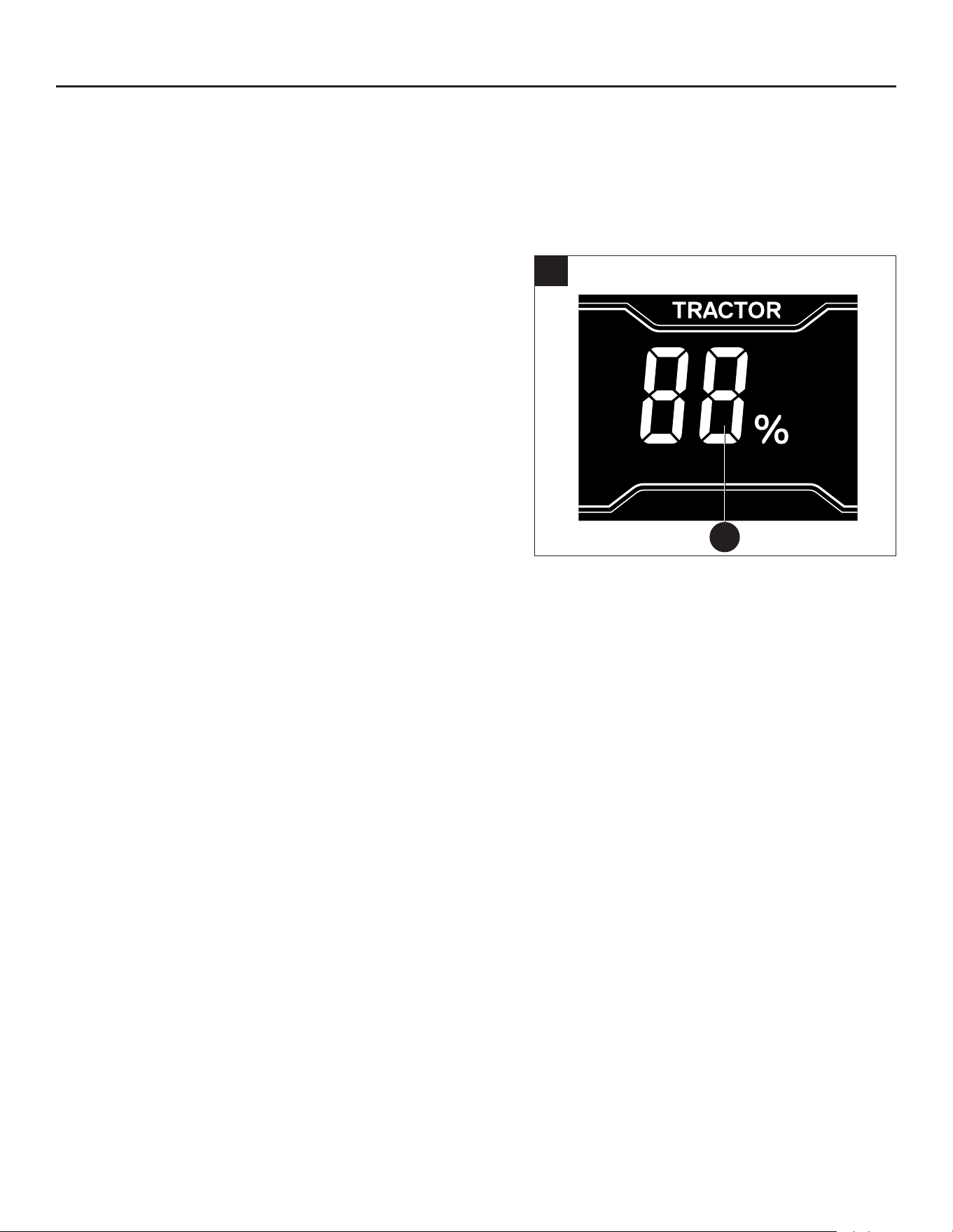
96
INSTRUCCIONES DE FUNCIONAMIENTO
NOTA: Las cuchillas de corte se pueden iniciar en cualquier momento una vez que la pantalla LCD
esté completamente iluminada y la palanca de control de dirección (D1) no esté empujada hacia
adelante en la dirección “R”. Para encender las cuchillas mientras conduce la podadora en reversa,
consulte la sección “Encendido de las cuchillas mientras conduce en reversa” en este manual.
Botón de arranque/apagado
• Presione brevemente el botón de arranque/apagado
(E1) y la pantalla LCD solo mostrará el “indicador
de combustible” (q) como se muestra en la Fig. 10b.
Presione brevemente el botón de arranque/apagado
de nuevo; la pantalla LCD se apagará.
• Con la llave de seguridad (EE) insertada, presione por
completo el pedal del freno de mano (K) y, al mismo
tiempo, presione el botón de arranque/apagado (E1)
durante más de 3 segundos; la pantalla LCD mostrará
la interfaz del operador completa. Presione de nuevo
el botón de arranque/apagado durante más de 3
segundos, y la pantalla LCD se apagará.
10b
q
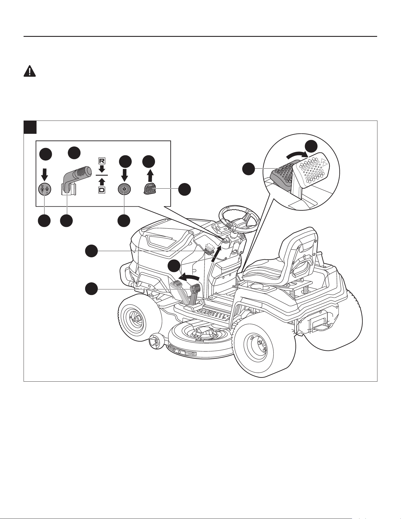
97
INSTRUCCIONES DE FUNCIONAMIENTO
11. Detener la podadora (Fig. 11)
PELIGRO:
• Nunca frene ni haga cambios de dirección bruscamente, en especial al maniobrar en una
pendiente. El volante y el pedal del acelerador están diseñados para una respuesta sensible.
Pisar con rapidez el acelerador o girar el volante en cualquier dirección podría provocar una
reacción de la podadora que puede causar lesiones graves.
>3s
1
3
5 6
4
2
11
G1 D1 E1
M
K
EE
Q
a. Presione el botón de encendido/apagado de las cuchillas (G1) para apagar los motores de las
cuchillas, y la luz del botón se apagará.
NOTA: Las cuchillas de corte pueden detenerse en cualquier momento.
b. Suelte el pedal del acelerador (Q).
c. Coloque la palanca de control de dirección (D1) en la posición “N”.
AVISO: Siempre coloque la palanca en la posición “N” cuando la podadora deje de funcionar, lo que
podría evitar un arranque inesperado si se presiona accidentalmente el pedal del acelerador.
d. Tire hacia arriba de la palanca de bloqueo del freno de mano (M) y pise a fondo el pedal del freno
de mano (K) para poner la podadora de césped en posición de freno de mano.

98
INSTRUCCIONES DE FUNCIONAMIENTO
e. Presione el botón de arranque/apagado (E1) durante más de 3 segundos hasta que la pantalla LCD
se apague. La luz del botón de arranque/apagado se apagará después de otros 3 segundos, lo que
signica que la podadora está apagada.
f. Retire la llave de seguridad (EE) de la podadora y guárdela en un lugar seguro.
ADVERTENCIA:
Se recomienda que el operador apague la podadora manualmente cuando no se utilice; de lo
contrario, se apagará de forma automática como se describe a continuación:
• En una situación en la que la pantalla LCD muestre el “indicador de combustible”, la podadora se
apagará de forma automática después de 5 minutos.
• En una situación en la que la pantalla LCD muestre la interfaz del operador, tanto los motores de
accionamiento como los motores de las cuchillas no están encendidos, la podadora se apagará
de forma automática después de 30 minutos.
ADVERTENCIA:
• No detenga la podadora en una pendiente. Detenga siempre la podadora en una supercie plana
y nivelada, y nunca la deje desatendida con la llave de seguridad puesta, ni siquiera por un breve
período. Dejar la llave de seguridad puesta puede permitir un uso no autorizado que podría
provocar lesiones personales graves.
ADVERTENCIA:
• Cuando la podadora deja de avanzar en una pendiente y el pedal del freno de mano no está puesto
en la posición de freno de mano, el indicador de audio seguirá emitiendo un pitido intermitente
para recordarle al operador que debe poner el freno de mano para que la podadora se detenga de
manera segura en la pendiente. Siempre ponga el freno de mano al levantarse del asiento. De lo
contrario, la podadora podría deslizarse cuesta abajo, lo que podría causar daños graves a
la podadora o lesiones personales.

99
INSTRUCCIONES DE FUNCIONAMIENTO
12. Conducir la podadora (Fig. 12)
Después de arrancar la podadora, siga estas instrucciones:
• Para conducir hacia adelante, tire la palanca de control de dirección (D1) hacia atrás en la
dirección “D” y mantenga el volante (V) recto sin girar. Controle la velocidad de conducción con el
pedal del acelerador (Q).
• Para conducir en reversa, empuje la palanca de control de dirección (D1) hacia adelante en la
dirección “R” y mantenga el volante (V) recto sin girar. Controle la velocidad de conducción con el
pedal del acelerador (Q).
NOTA: Al tirar de la palanca de control de dirección de la posición “D” a la posición “R” MIENTRAS
conduce hacia adelante, la podadora reducirá su velocidad a cero y, luego, cambiará en reversa.
NOTA: Al cambiar entre avance y reversa durante la conducción, mueva la palanca de control de
dirección directamente de un extremo al otro sin detenerse en la posición “N”; de lo contrario, la
podadora podría dejar de moverse.
• Para girar a la izquierda, gire el volante (V) hacia la izquierda.
• Para girar a la derecha, gire el volante (V) hacia la derecha.
AVISO: No se recomienda el movimiento rápido del volante ya que pueden producirse daños a los
componentes eléctricos de la podadora.
AVISO: Los giros agresivos pueden rayar o dañar el césped. Realice giros a baja velocidad de
conducción.
• Para detener o disminuir la velocidad, suelte el pedal del acelerador (Q) despacio.
• Para aumentar la velocidad, pise el pedal del acelerador (Q) hasta el fondo. Cuanto más fuerte se
pise el pedal del acelerador (Q), más rápido se desplazará la podadora.
PELIGRO: Manténgase al menos a dos anchos de corte (7 pies/2.13 metros) de distancia de
zanjas, desniveles o agua. Las ruedas delanteras pueden girar cuando la podadora está parada,
incluso con el freno aplicado, y hacer que la podadora se salga del borde o caiga al agua y provoque
la muerte o lesiones personales graves.
ADVERTENCIA: Esté atento a lo que hay detrás de la podadora antes de dar marcha atrás. NO
realice movimientos hacia atrás a menos que sea absolutamente necesario. Mire siempre hacia abajo
y hacia atrás antes y mientras retrocede para asegurarse de que no ingrese ningún niño, transeúnte
o mascota al área de corte. Recuerde que un descuido de una fracción de segundo es suciente para
provocar la muerte o lesiones graves.
ADVERTENCIA: Asegúrese de haber congurado correctamente la dirección de conducción
prevista con el volante antes de pisar el pedal del acelerador. De lo contrario, podría conducir la
podadora en una dirección no deseada, lo que podría provocar la pérdida de control o un accidente.
ADVERTENCIA: Tenga cuidado al cruzar caminos de gravilla o entradas de garaje. Antes de
cruzar, apague los motores de las cuchillas y levante la plataforma de corte a la posición más alta
para minimizar la posibilidad de rebotes. Conduzca lentamente para evitar la pérdida de tracción y de
control.
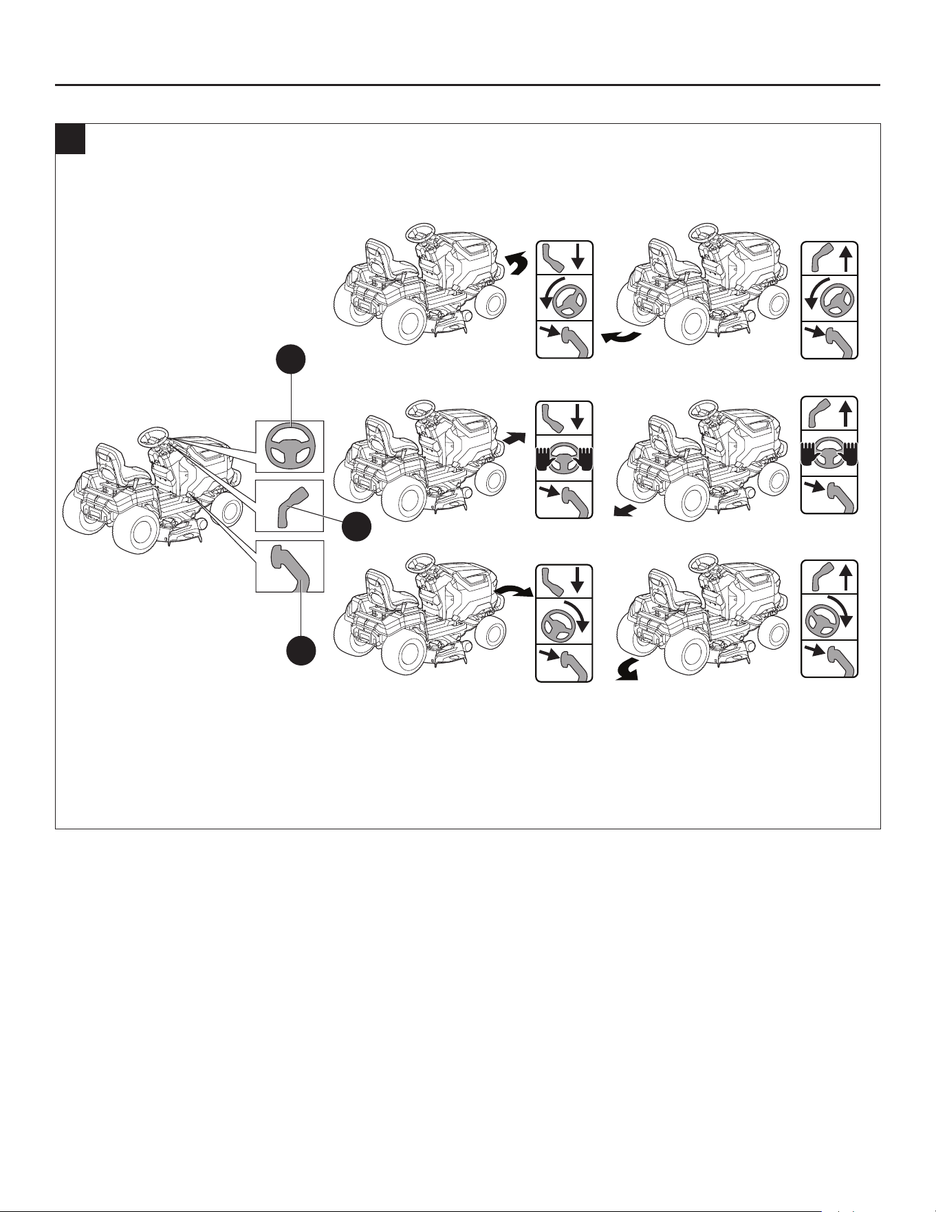
100
INSTRUCCIONES DE FUNCIONAMIENTO
D
D
D
R
R
R
12
V
D1
Q
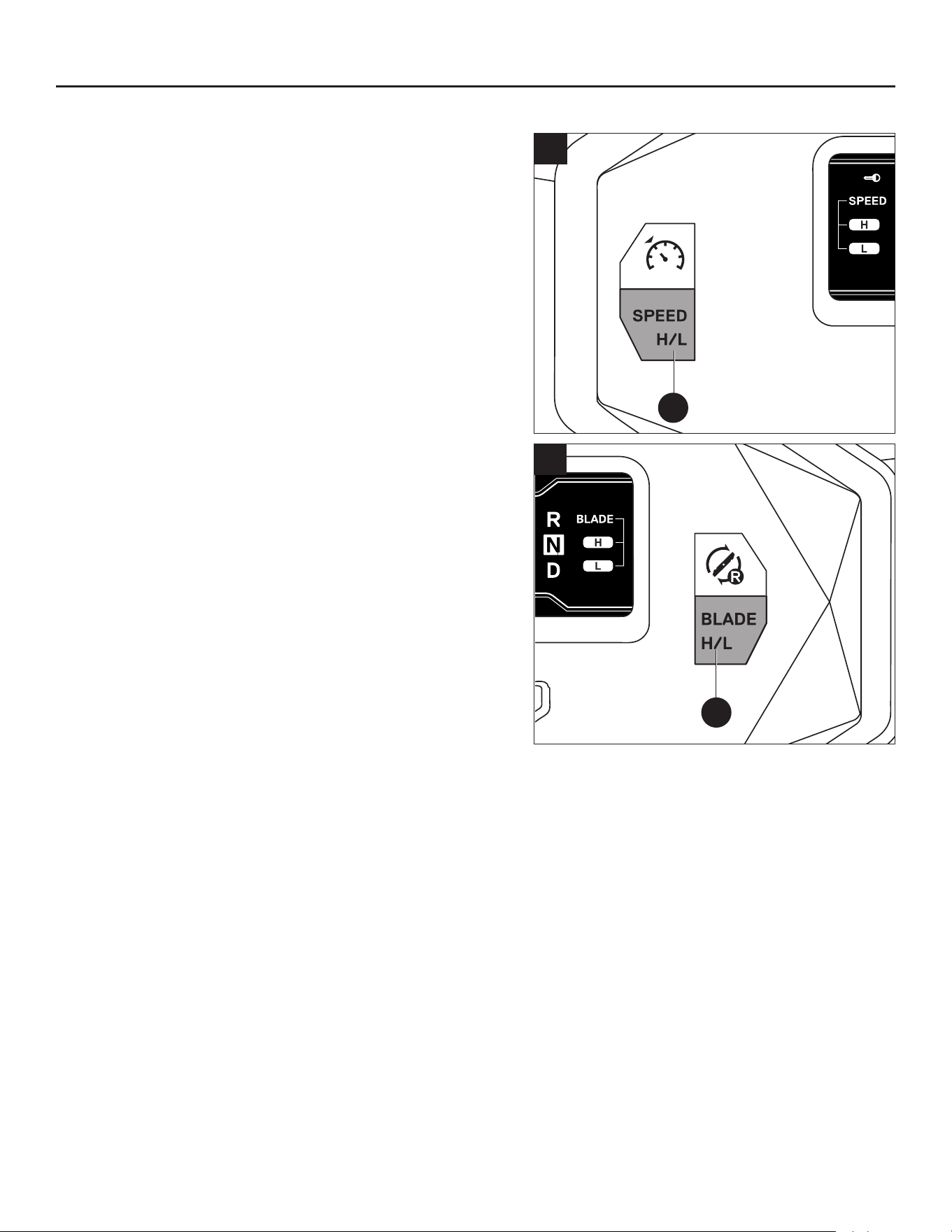
101
INSTRUCCIONES DE FUNCIONAMIENTO
13. Personalización de las conguraciones de corte
y conducción
Para obtener la mejor experiencia de corte, recomendamos
personalizar las siguientes conguraciones según su
situación.
Para seleccionar su nivel de velocidad de conducción
(Fig. 13a):
El nivel de velocidad de conducción establece la
velocidad máxima de conducción de la podadora.
Presione el botón de ajuste de velocidad de conducción
(I1) para alternar entre nivel bajo (“L”) y nivel alto (“H”).
Velocidad de conducción baja: para bordes y recortes
a baja velocidad, o al cortar el césped o conducir en
áreas estrechas.
Velocidad de conducción alta: maximice el área de
cobertura al cortar céspedes grandes y planos.
Para seleccionar su nivel de velocidad de cuchillas
(Fig. 13b):
El usuario puede personalizar la velocidad de las
cuchillas según las condiciones del césped. El tiempo
de funcionamiento aumentará cuando se corte a baja
velocidad de cuchillas.
Presione el botón de ajuste de velocidad de cuchillas
(C1) para alternar entre nivel bajo y nivel alto.
Velocidad de las cuchillas baja (“L”): proporciona el nivel de ruido más bajo y el tiempo de
funcionamiento más prolongado.
Velocidad de las cuchillas alta (“H”): para césped alto o en condiciones de césped
extremadamente húmedo.
13a
I1
C1
13b
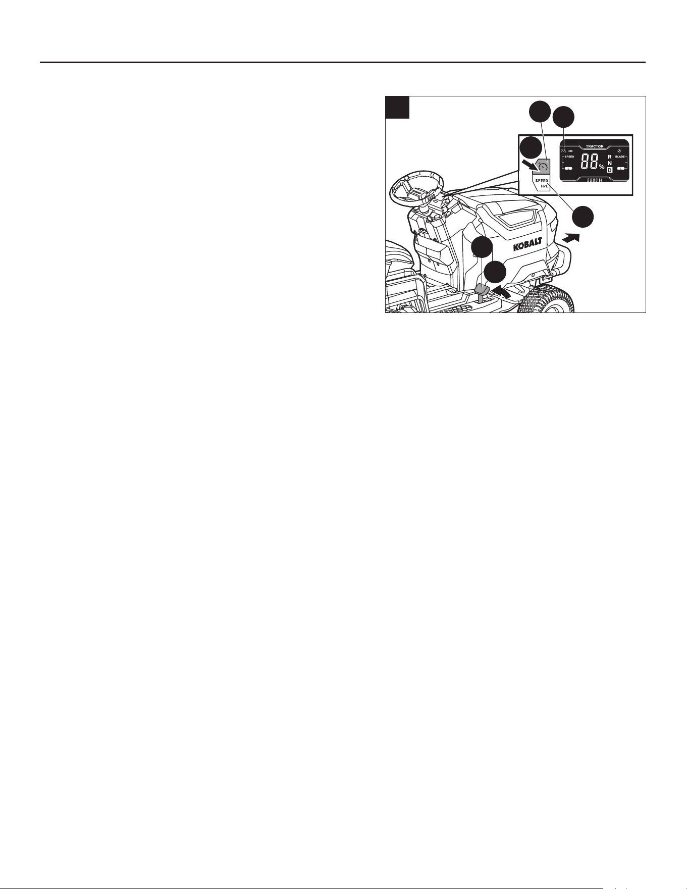
102
INSTRUCCIONES DE FUNCIONAMIENTO
14. Uso del control de crucero (CCS)
Durante la conducción hacia adelante, se puede
congurar la podadora para que continúe a la velocidad
deseada sin tener que pisar el pedal del acelerador.
Para activar (ingresar) el control de crucero (CCS)
(Fig. 14)
a. Mientras conduce hacia adelante a una velocidad
cómoda, presione el botón CCS (J1); el ícono CCS (a)
se iluminará en la pantalla LCD.
b. Luego, suelte el pedal del acelerador (Q), y la podadora
continuará avanzando a la velocidad actual.
NOTA: Es posible que el nivel de velocidad de
conducción que se muestra en la pantalla LCD no represente con precisión la velocidad de
conducción real de la podadora en el control de crucero. Presione el botón de ajuste de la velocidad
de conducción (I1) para “refrescar” el nivel de velocidad de conducción en la pantalla LCD.
c. Presione el botón de ajuste de velocidad de conducción (I1) para aumentar o disminuir la velocidad
del control de crucero hasta alcanzar la velocidad deseada.
Para detener (salir) del control de crucero (CCS), puede elegir una de las tres formas:
• Pise el pedal del acelerador (Q) hasta el fondo y siga haciéndolo. La función CCS se detendrá, y la
podadora seguirá funcionando.
• Pise ligeramente el pedal del acelerador (Q) y, luego, suéltelo. La podadora y la función CCS se
detendrán.
• Presione el botón CCS (J1). La podadora y la función CCS se detendrán.
NOTA: Cuando empuje la palanca de control de dirección (D1) hacia adelante en la posición “N” o “R”,
la función CCS también se detendrá.
NOTA: Cuando se detiene el CCS, el ícono CCS (a) desaparecerá de la pantalla LCD.
NOTA: Si se presiona el pedal del freno de mano, la podadora se detendrá, pero el ícono CCS (a)
parpadeará en la pantalla LCD para indicar que el CCS está en espera. En este caso, suelte el pedal
del freno de mano, presione el botón CCS (J1), y la podadora reanudará la marcha automáticamente
y el ícono CCS (a) dejará de parpadear.
2
1
14
a
I1
J1
Q
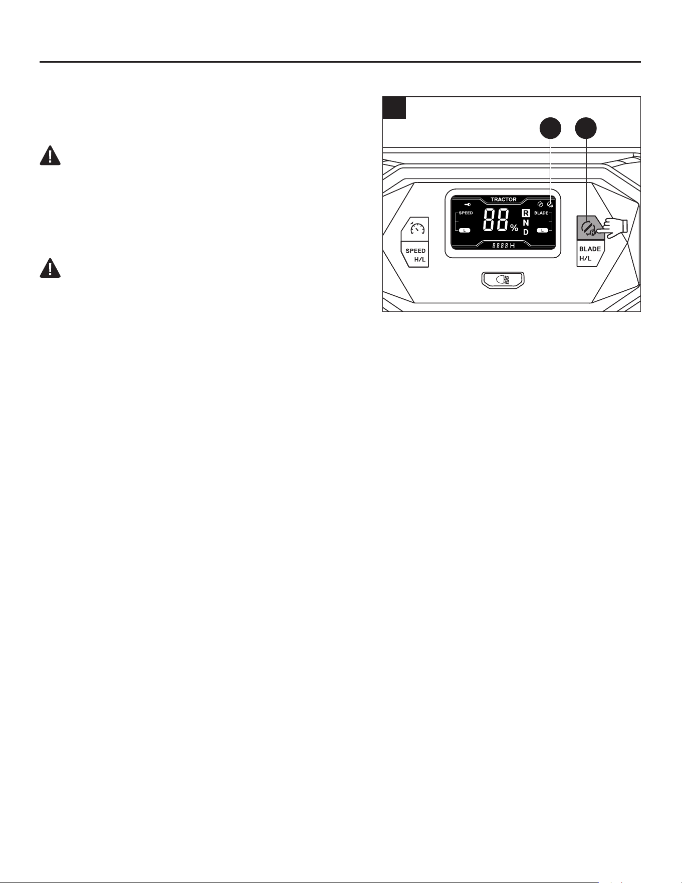
103
>3s
15
B1g
INSTRUCCIONES DE FUNCIONAMIENTO
15. Encender las cuchillas al conducir en reversa
AVISO: No se recomienda cortar en reversa.
ADVERTENCIA:
• Tenga extrema precaución al cortar el césped en
reversa. Asegúrese siempre de que ninguna persona
entre en el área de trabajo, especialmente niños
pequeños, antes y mientras corta el césped en
reversa.
ADVERTENCIA:
• El campo de visión del operador podría verse
limitado al operar la podadora de césped con el kit de
ensacadora opcional adjunto. Siempre se debe tener
extrema precaución y familiaridad con el entorno antes y mientras se corta en reversa.
Para activar (ingresar) el corte en reversa (Fig. 15)
Los motores de las cuchillas se pueden encender al conducir en reversa, si se desea.
Después de cada arranque, el ícono de cortar el césped en reversa (g) desaparecerá de la pantalla
LCD, lo que signica que los motores de las cuchillas no se podrán encender al conducir en reversa.
a. Siéntese en el asiento de la podadora.
b. Presione el botón de arranque/apagado (E1) durante más de 3 segundos, y la pantalla LCD mostrará
la interfaz del operador.
c. Presione el botón de cortar en reversa (B1) durante más de 3 segundos, y el ícono de cortar en
reversa (g) se iluminará en la pantalla LCD, lo que signica que los motores de las cuchillas se
pueden encender al conducir en reversa.
Para detener (salir) del corte en reversa, puede elegir una de las cuatro formas:
• Presione el botón de corte en reversa (B1) una vez.
• Levántese del asiento de la podadora.
• Presione el botón de arranque/apagado (E1) durante más de 3 segundos para apagar la pantalla
LCD.
• Retire la llave de seguridad (EE) para apagar la podadora.
NOTA: Cuando se detiene el corte en reversa, el ícono de corte en reversa (g) desaparecerá de la
pantalla LCD.

104
INSTRUCCIONES DE FUNCIONAMIENTO
16. Faros LED
Los faros LED (L) se pueden encender y apagar
mediante el botón de luz LED (H1). El ícono de los faros
LED (e) se iluminará en la pantalla LCD.
17. Puerto USB tipo A
El puerto USB-A (U) proporciona energía de carga de 5
voltios CC con un consumo combinado de 1.5 amperios
para su teléfono celular, reproductor MP3 u otros
dispositivos USB. Consulte el manual del propietario
de su dispositivo para conocer sus requisitos de carga
especícos.
AVISO:
• Intentar cargar dispositivos cuyo consumo combinado
exceda los 1.5 amperios podría dañar el puerto USB o
la podadora.
• No se puede alimentar el puerto USB cuando la
podadora está en modo de carga.
• Cuando no se utilice, asegúrese de que la cubierta del
puerto USB esté cerrada para proteger el puerto USB
del agua, la humedad o el polvo.
18. Funcionamiento en pendientes
Mira la sección “Especicaciones sobre la pendiente”
en este manual para obtener instrucciones de seguridad
antes de operar en pendientes.
PELIGRO:
• Las pendientes son un factor importante relacionado con los accidentes por vuelcos que pueden
provocar lesiones graves o la muerte. El funcionamiento en pendientes requiere precauciones
adicionales. Si se siente incómodo en una pendiente, no corte el césped en ese lugar. Por su
seguridad, no intente cortar en pendientes pronunciadas de más de 15 grados. Haga una copia
o recorte la imagen de la guía de pendientes (Fig. 18) y úsela para determinar si su pendiente es
demasiado pronunciada para una operación segura.
ADVERTENCIA: Abra la palanca de bloqueo del freno de mano (M) y presione el pedal del
freno de mano (K) inmediatamente para ponerlo en la posición de freno en caso de que ocurra
alguna emergencia. La podadora se detendrá inmediatamente y no se deslizará cuesta abajo.
• Corte hacia arriba y hacia abajo, no a lo largo de las pendientes.
• No pode sobre el césped húmedo. El césped mojado puede hacer que los neumáticos pierdan
tracción o patinen en las pendientes, aunque los frenos funcionen correctamente.
16
e
H1
L
17
U

105
INSTRUCCIONES DE FUNCIONAMIENTO
• Esté atento a los agujeros, surcos, rocas, objetos ocultos o bultos que puedan afectar su
funcionamiento. El césped alto puede ocultar los obstáculos. Retire todos los objetos como rocas,
ramas de árboles, etc., que puedan ser lanzados por las cuchillas.
• No corte cerca de desniveles, zanjas o terraplenes.
• Conduzca despacio y no haga cambios bruscos de velocidad o dirección.
• Evite detenerse en una pendiente si es posible. Si es inevitable detenerse en una pendiente,
asegúrese de poner el freno de mano. Al reiniciar, utilice la velocidad más baja posible. Si es
necesario girar, tenga extrema precaución al cambiar de dirección y gire siempre cuesta abajo.
• Si en algún momento los neumáticos pierden tracción mientras conduce en una pendiente, apague
las cuchillas y avance lenta y cuidadosamente cuesta abajo.
• Si utiliza la ensacadora opcional u otros accesorios, nunca opere la podadora en ángulos de
pendiente superiores a 10 grados. Tenga mucho cuidado y opere la podadora lentamente cuando
opere en pendientes, ya que estos accesorios pueden cambiar la estabilidad de la podadora.
Asistencia en pendiente
Cuando se reinicia la podadora en una pendiente, en el momento en que se presiona el pedal
del acelerador, la podadora se mantendrá quieta en la pendiente sin deslizarse a lo largo de la
pendiente. Una vez que se presiona con más fuerza el pedal del acelerador, la podadora comenzará
a avanzar normalmente. Esta es una función de asistencia en pendiente para un arranque seguro de
la podadora.
• Cuando la podadora deja de funcionar, se suelta el pedal del acelerador, pero el pedal del freno de
mano no está en la posición de freno de mano, el indicador de audio emitirá pitidos intermitentes.
El indicador de audio ya no sonará cuando el pedal del freno de mano se coloque en la posición de
freno de mano.
ADVERTENCIA: Coloque siempre el pedal del freno de mano en la posición de freno de
mano cuando la podadora deje de circular en una pendiente. De lo contrario, la podadora
podría deslizarse cuesta abajo, lo que podría causar daños graves a la podadora o lesiones
personales.
• Al volver a conducir en una pendiente, quite el pedal del freno de mano y pise el pedal del
acelerador inmediatamente. De lo contrario, cuando se suelta el pedal del freno de mano pero no
se presiona el pedal del acelerador, la podadora podría deslizarse cuesta abajo y el indicador de
audio no emitirá un pitido.
• Cuando conduzca la podadora en una pendiente, nunca intente pisar el pedal del freno de
mano para reducir la velocidad durante la conducción. De lo contrario, cuando se presiona el
pedal del freno de mano pero no está puesto en la posición de freno de mano, la podadora puede
deslizarse cuesta abajo una vez que se suelta el pedal del freno de mano.
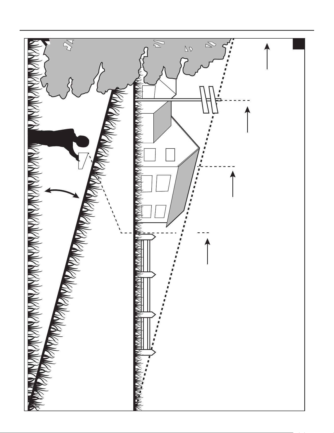
106
INSTRUCCIONES DE FUNCIONAMIENTO
15
o
Observe y sostenga el nivel de la línea con
un árbol vertical…
Observe y sostenga el nivel de la
línea con una varilla...
o la esquina de un edicio...
o el poste de una cerca.
18
Pliegue por la línea punteada (representa una pendiente de 15 grados)
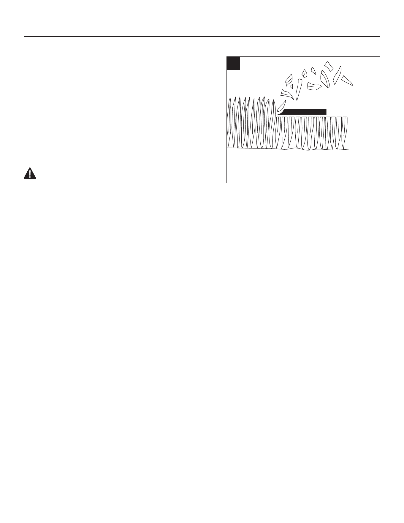
107
INSTRUCCIONES DE FUNCIONAMIENTO
19. Consejos de corte
AVISO: El rendimiento de la podadora será mucho
mayor si se usa una cuchilla alada, especialmente si
se corta césped alto. Asegúrese de vericar el lo de la
cuchilla antes de cortar.
• Verique que no haya piedras, palos, cables ni otros
objetos en el césped que puedan dañar las cuchillas
de corte o los motores de la podadora. Es posible que
la podadora lance estos objetos accidentalmente en
cualquier dirección y provoque lesiones personales
graves al operador y a otras personas.
ADVERTENCIA: Si golpea un objeto extraño,
apague la podadora. Inspeccione minuciosamente la
podadora y repare si hay algún daño antes de volver a encenderla y usarla. La vibración excesiva de
la podadora durante su funcionamiento advierte un daño. La unidad se debe inspeccionar y reparar
de inmediato.
• El resultado del corte será mejor con una velocidad de cuchilla alta y una velocidad de conducción
baja. Si el césped no es demasiado largo y denso, se puede aumentar la velocidad de conducción
sin que afecte negativamente al resultado del corte.
• Al cortar césped espeso, reduzca la velocidad de conducción para permitir un corte más ecaz y
una descarga adecuada de los recortes.
• Comience con una altura de corte alta y redúzcala hasta lograr el resultado de corte deseado.
El césped de más de 152 mm (6 pulg.) de largo se debe cortar dos veces, a alturas de corte
sucesivamente más bajas.
• Para mantener un césped sano, solo corte un tercio o menos de su altura total (Fig. 19). El césped
promedio debe tener aproximadamente de 38 a 51 mm (1-1/2 a 2 pulg.) de largo durante los meses
fríos y de 51 a 83 mm (2 a 3-1/4 pulg.) de largo durante los meses cálidos. Para obtener un césped más
saludable y con mejor apariencia, corte con más frecuencia después de un crecimiento moderado.
• No corte el césped mojado. Cortar en supercies mojadas puede provocar la pérdida de control y
que las ruedas se hundan en el césped blando. El césped mojado se adherirá a la parte inferior de
la plataforma e impedirá el embolsado o triturado correcto de los recortes de césped.
• El césped nuevo o grueso puede requerir un corte más angosto o una altura de corte más alta.
• Mantenga limpios la plataforma de corte y el conducto de descarga lateral. Retire los recortes de
césped, las hojas, la suciedad y cualquier otro residuo acumulado antes y después de cada uso.
Consulte la sección “Limpieza de la maquina” en este manual.
20. Consejos para aumentar el tiempo de funcionamiento
Para obtener un tiempo de funcionamiento más prolongado, siga estas pautas:
• No corte más de 38 mm (1.5 pulg.) de césped en una sola pasada.
• No corte el césped mojado.
• Asegúrese de que las cuchillas estén aladas.
• Asegúrese de que la parte inferior de la plataforma esté limpia.
• Reduzca la velocidad de las cuchillas: utilice el nivel de velocidad baja de las cuchillas.
• No utilice el tapón para compuesto orgánico.
• No cargue dispositivos externos mediante el puerto USB.
19
1/3
2/3

108
INSTRUCCIONES DE FUNCIONAMIENTO
21. Uso en clima frío
AVISO: En climas extremadamente fríos, es posible que el motor de las cuchillas y la función de
accionamiento no se inicien de forma correcta debido a la protección de baja temperatura. No realice
intentos repetidos que puedan dañar la máquina. Almacene siempre la podadora de césped en
un ambiente cálido. Reinicie la podadora cuando esté caliente. La temperatura de funcionamiento
recomendada es de 0 °C a 40 °C (32 °F a 104 °F).
22. Indicador de audio (pitidos)
La podadora está equipada con un indicador de audio que emitirá un pitido en determinadas
situaciones. Sonará en los siguientes momentos:
• La podadora arranca normalmente, y la pantalla LCD se ilumina con todos los íconos e indicadores.
El pitido sonará una vez.
• La podadora se apaga normalmente. El pitido sonará una vez.
• Al comenzar a conducir en reversa o cambiar la dirección de conducción de adelante a atrás
mientras conduce, el pitido sonará seis veces.
• Cuando la carga de la batería disponible es muy baja, la podadora pasará al modo de bajo
consumo y los pitidos seguirán sonando de forma intermitente hasta que se presione el botón de
encendido/apagado de las cuchillas para apagarlas.
• Cuando la podadora esté sobrecargada o sobrecalentada, sonará un pitido.
• Cuando se muestra algún código de falla en la pantalla LCD, el pitido sonará una vez.
• Cuando la podadora deja de circular en una supercie nivelada, se suelta el pedal del acelerador,
el operador se levanta del asiento sin poner el pedal del freno de mano en la posición de freno de
mano, los pitidos sonarán continuamente para recordarle al operador que ponga el freno de mano
por seguridad.
• Cuando la podadora se detiene en una pendiente, se suelta el pedal del acelerador, pero el pedal
del freno de mano no está puesto en la posición de freno de mano, sonarán continuamente unos
pitidos para recordar al operador que ponga el freno de mano por seguridad.
• Al entrar o salir del CCS (Sistema de control de crucero), el pitido sonará dos veces.
• Cuando la podadora comience a cargarse correctamente, sonará un pitido.

109
CUIDADO Y MANTENIMIENTO
ADVERTENCIA: Antes de realizar cualquier mantenimiento, detenga la podadora en una
supercie nivelada y espere a que las cuchillas se detengan por completo. Ponga el freno de mano,
retire la llave de seguridad y espere a que se apague la luz del botón de arranque/parada para evitar
un arranque accidental y posibles lesiones personales graves.
ADVERTENCIA: para garantizar la seguridad personal, no permita nunca que ninguna persona
se siente en la máquina o la maneje mientras se esté realizando cualquier tarea de mantenimiento.
ADVERTENCIA: Cuando realice reparaciones, utilice solo piezas de repuesto idénticas a las de
fabricación. El uso de cualquier otra pieza puede ser peligroso o causar daños en el producto. Para
garantizar la seguridad y conabilidad, toda reparación debe realizarse por un técnico de reparación
calicado.
ADVERTENCIA: Cumpla estrictamente con todas las especicaciones de apriete de la llave
dinamométrica. Si no lo hace, podría causar lesiones personales graves.
AVISO: Permanezca alerta ante ruidos inusuales, ya que podrían estar indicando un problema.
Inspeccione a simple vista el producto para detectar cualquier desgaste o daño anormal. Inspeccione
periódicamente todo el producto en busca de piezas dañadas, faltantes o sueltas, como tornillos, tuercas,
pernos, tapas, etc., además de enredos de cables y cuerdas. Apriete con rmeza todos los sujetadores y
tapas, y no opere este producto hasta que se reemplacen todas las piezas faltantes o dañadas.
Intervalo de servicio de
mantenimiento
Procedimiento de mantenimiento
Antes de cada uso o
diariamente
◾
Compruebe el sistema de bloqueo de seguridad.
◾
Compruebe a simple vista si los neumáticos están inados.
◾
Inspeccione las cuchillas.
◾
Inspeccione todo el producto en busca de piezas dañadas,
faltantes o sueltas, como el conducto de descarga lateral,
tornillos, tuercas, pernos, tapas, etc., y asegúrese de que todas
las protecciones estén en su lugar y funcionando correctamente.
◾
Verique y asegúrese de que el pedal del acelerador se pueda
presionar y soltar de forma correcta.
◾
Revise el amortiguador del volante. El volante debe girarse con
cierta resistencia.
Después de cada uso
◾
Limpie la podadora y lave la plataforma.
Cada 25 horas
◾
Revise la presión de los neumáticos.
Cada 100 horas
◾
Verique las ruedas delanteras y asegúrese de que la tuerca
esté ajustada al torque recomendado de 66 a 68 pies-libras
(90 – 92 Nm).
◾
Verique las ruedas traseras y asegúrese de que las 4 tuercas
estén apretadas al torque recomendado: 74 a 76 pies-libras
(101-103 Nm).
Cada 200 horas
◾
Compruebe las ruedas delanteras y asegúrese de que giren
libremente.

110
CUIDADO Y MANTENIMIENTO
Intervalo de servicio de
mantenimiento
Procedimiento de mantenimiento
Cada medio año
◾ Compruebe el pedal del freno de mano. Tire hacia arriba de la
palanca de bloqueo del freno de mano y pise el pedal del freno
para poner en posición de freno de mano. Empuje manualmente
la podadora hacia adelante para ver si se puede mover sin que
giren las ruedas traseras. Si la podadora se mueve y las ruedas
traseras giran, comuníquese con el Servicio al Cliente de Kobalt
y haga que un técnico de servicio calicado lo repare.
Antes de almacenar
◾
Retire la llave de seguridad de la podadora.
◾
Realice todos los procedimientos de mantenimiento enumerados
anteriormente y limpie a fondo la podadora.
◾
Inspeccione todo el producto en busca de piezas dañadas,
faltantes o sueltas. Reemplace o apriete las piezas
correspondientes antes del almacenamiento.
Cada año
◾
Lubrique los casquillos de los ejes de las ruedas delanteras.
Consulte el capítulo “Lubricación de los casquillos de los ejes
de las ruedas delanteras”.
MANTENIMIENTO GENERAL
• Evite utilizar solventes para limpiar las piezas de plástico. La mayoría de los plásticos tienden a
dañarse si se usan distintos tipos de solventes comerciales. Utilice un paño limpio para eliminar la
suciedad, el polvo, el aceite, la grasa, etc. El aerosol repelente de insectos puede dañar el plástico
y las supercies pintadas. No rocíe repelente de insectos cerca de la podadora.
• La exposición prolongada a la luz solar dañará algunas supercies.
• Si accidentalmente deja la podadora bajo la lluvia, use un paño limpio y seco para secar el asiento,
el panel de control, etc., antes de reiniciarla o guardarla.
ADVERTENCIA:
• Nunca deje que el líquido de frenos, la gasolina, los productos a base de petróleo, los aceites
penetrantes, entre otros, entren en contacto con las piezas de plástico. Los químicos pueden dañar,
debilitar o destruir el plástico, lo que puede causar lesiones personales graves.
Limpieza de la máquina
Elimine cualquier acumulación de césped y hojas sobre la carcasa de la podadora o alrededor
de ella. Use protección para los ojos. Y use aire comprimido después de cada uso para limpiar la
carcasa de la podadora o la parte superior de ella.
La parte inferior de la plataforma también debe limpiarse con el puerto de lavado después de cada
uso, ya que se acumularán recortes de césped, hojas, suciedad y otros desechos, especialmente
cuando el césped está mojado o tiene un alto contenido de humedad. Esta acumulación no es
deseable, ya que se endurecerá, lo que restringirá el movimiento de las cuchillas y del aire. Esto
probablemente dará como resultado una peor calidad de corte e incluso promoverá la oxidación y la
corrosión.
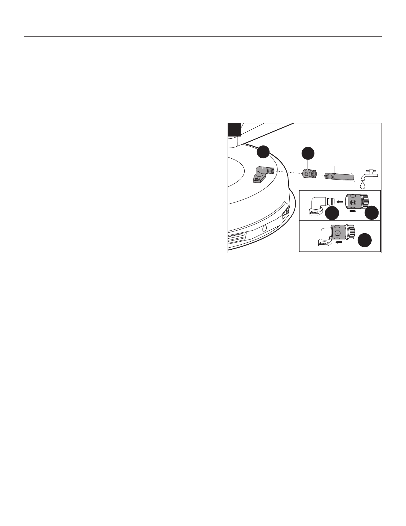
111
b
2
1
3
20
Manguera
para jardín
D
FF
CUIDADO Y MANTENIMIENTO
Uso del puerto de lavado para limpiar la plataforma
AVISO: Siga este procedimiento después de CADA USO para evitar la acumulación y eliminar los
productos químicos corrosivos para el césped.
IMPORTANTE: Puede lavar la máquina con un detergente suave y agua. No lave la máquina a
presión. Evite el uso excesivo de agua, especialmente cerca del panel de control, debajo del asiento,
alrededor de los motores y todos los componentes y rodamientos eléctricos.
a. Active el freno de mano. Consulte la sección “Ajuste
del freno de mano” en este manual.
b. Ajuste la altura de la plataforma al mínimo. Consulte la
sección “Ajuste de la altura de corte” de este manual.
c. Conecte el acoplador rápido del puerto de lavado (FF)
suministrado a una manguera para jardín (no incluida).
d. Conecte la manguera para jardín con el acoplador
rápido (FF) al puerto de lavado (D) en la plataforma
de corte como se muestra en la Fig. 21 hasta que
escuche un clic claro. El puerto de lavado está en el
lado izquierdo de la plataforma de corte.
e. Abra el agua.
f. Introduzca la llave de seguridad (EE), presione el pedal
del freno (K) y simultáneamente presione el botón de
arranque/apagado (E1) durante más de 3 segundos para iluminar la pantalla LCD.
g. Presione el botón de arranque/apagado de las cuchillas (G1) durante más de 3 segundos para
arrancar los motores de las cuchillas y ajustar la velocidad de las cuchillas al nivel alto. Consulte la
sección “Para seleccionar su nivel de velocidad de cuchillas” en este manual.
h. Deje correr agua debajo de la plataforma durante aproximadamente un minuto.
i. Presione el botón de arranque/apagado de las cuchillas (G1) de nuevo para apagar los motores de
las cuchillas.
j. Cierre el agua y retire la manguera para jardín y el acoplador rápido (FF) del puerto de lavado.
k. Retire el acoplador rápido (FF) de la manguera para jardín y guárdelo en un lugar seguro para uso
futuro.
l. Apague la podadora por completo. Consulte la sección “Detener la podadora”.
NOTA: Al limpiar la plataforma con el puerto de lavado, la podadora puede estar en modo de
trituración o de descarga lateral.
NOTA: Si la plataforma no está limpia después de un ciclo de lavado, repita el proceso hasta que
esté completamente limpia.

112
CUIDADO Y MANTENIMIENTO
NIVELACIÓN DE LA PLATAFORMA
ADVERTENCIA: Siempre use guantes para trabajo pesado y envuelva los bordes cortantes
con harapos u otros materiales para protegerse las manos cuando realice cualquier tarea de
mantenimiento a las cuchillas para podadora.
• Antes de decidir que es necesario nivelar la plataforma, asegúrese de que los neumáticos estén
correctamente inados a la presión recomendada (consulte la sección “COMPROBAR LA
PRESIÓN DE LOS NEUMÁTICOS” en este manual). Un inado excesivo o insuciente de los
neumáticos puede afectar al aspecto del césped cortado, y un inado adecuado de los neumáticos
puede ser todo lo que se necesita para resolver los problemas de corte desigual. Si los neumáticos
están poco o demasiado inados, la plataforma no puede ajustarse correctamente.
• Verique que no haya cuchillas dobladas antes de nivelar. Retire y reemplace las cuchillas
dobladas. Consulte la sección “REEMPLAZO DE LAS CUCHILLAS DE CORTE” en este manual
como referencia.
• Ajuste la plataforma mientras la podadora está sobre una supercie nivelada. Eleve la plataforma a
la posición más alta.
NOTA: Las ruedas protectoras de la plataforma de la podadora no deben hacer contacto con el suelo
al nivelar la plataforma.
NOTA: La plataforma debe ajustarse un poco más arriba en la parte trasera.
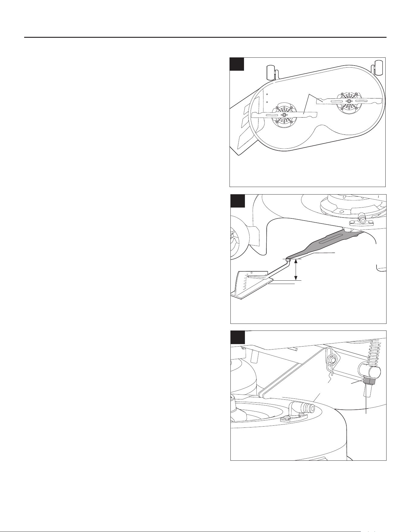
113
21c
Contratuerca
El hombro
mirando
hacia
afuera
21b
Indicador de nivelación
Borde inferior
de la cuchilla
Distancia
21a
Cuchillas de lado a lado
CUIDADO Y MANTENIMIENTO
Herramientas necesarias (no incluidas): una llave
española de 21 mm (13/16 pulg.), una llave española
de 18 mm (23/32 pulg.) o una llave inglesa ajustable, un
indicador de nivelación.
Para realizar un ajuste a los lados
a. Apague la podadora, ponga el freno de mano y retire
la llave de seguridad.
b. Coloque ambas cuchillas de modo que los extremos
apunten hacia los lados de la podadora (Fig. 21a).
c. En el borde exterior de cada cuchilla, mida la distancia
desde el borde inferior del costado de la cuchilla hasta
el suelo (Fig. 21b). Si la distancia entre los dos lados
es mayor que 5 mm (13/64 pulg.), es necesario realizar
un ajuste a los lados.
d. En el lado que desea ajustar, use una llave española
de 21 mm (13/16 pulg.) o una llave inglesa ajustable
(no incluida) para ajustar la contratuerca en la parte
trasera de la podadora de césped (Fig. 21c).
e. Mida nuevamente. Continúe ajustando y midiendo
hasta que la diferencia entre las distancias en cada
lado esté dentro de 5 mm (13/64 pulg.).
f. Proceda al ajuste de adelante hacia atrás o vuelva a
apretar las tuercas.
NOTA: En caso de que la contratuerca de la parte
trasera se retire accidentalmente de la máquina, vuelva
a montarla con el reborde de la contratuerca hacia
afuera. No son necesarias las dos tuercas en el varillaje
de suspensión.
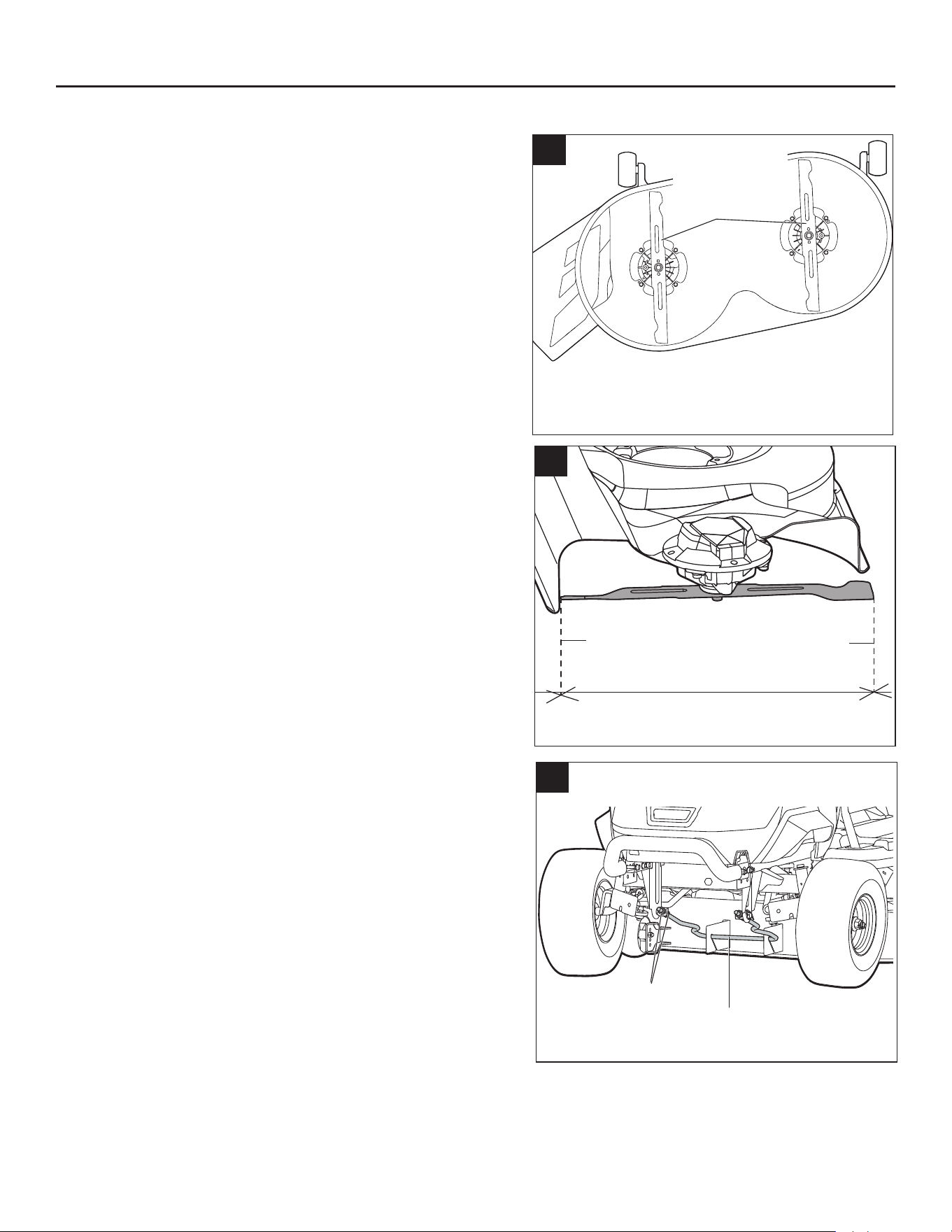
114
CUIDADO Y MANTENIMIENTO
Para realizar el ajuste de adelante hacia atrás
AVISO: Siempre nivele la plataforma de lado a lado
antes de realizar un ajuste de adelante hacia atrás.
a. Coloque ambas cuchillas de modo que los extremos
apunten hacia adelante y atrás de la podadora
(Fig. 22a).
b. Mida la distancia desde la punta de una cuchilla
hasta el suelo (ver Fig. 22b). Para obtener mejores
resultados, la punta delantera de la cuchilla debe
estar entre 2 mm a 10 mm (5/64 a 25/64 pulg.) más
baja que la punta trasera.
c. Si es necesario un ajuste de adelante hacia atrás, use
una llave española de 18 mm (23/32 pulg.) o una llave
inglesa ajustable (no incluida) para ajustar las cuatro
tuercas en el varillaje de suspensión (dos para cada
lado) (Fig. 22c).
AVISO: Asegúrese de girar las tuercas
correspondientes en ambos lados por igual para evitar
alterar la medida de lado a lado.
d. Mida nuevamente para vericar que la punta delantera
esté ahora 2 mm a 10 mm (5/64 a 25/64 pulg.) más
baja que la punta trasera. Si no es así, continúe
ajustando y midiendo hasta que lo estén.
e. Apriete las tuercas nuevamente. El torque
recomendado para las tuercas es de 38-42 pie-libras
(52-57 Nm).
22c
Varillaje de suspensión
Tuercas
22a
Cuchillas
de adelante
hacia atrás
22b
Distancia
desde la punta
delantera al
suelo
Distancia
desde la punta
trasera al
suelo
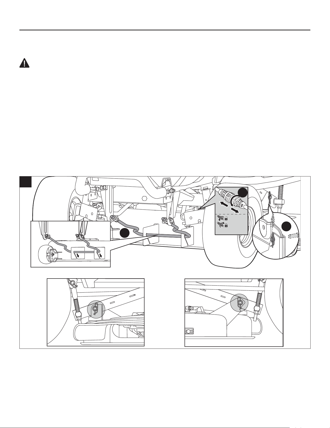
115
CUIDADO Y MANTENIMIENTO
QUITAR LA PLATAFORMA
ADVERTENCIA:
• Asegúrese de que la podadora esté correctamente asegurada y que el freno de mano esté puesto
antes de continuar.
Siga los pasos a continuación para retirar la plataforma del producto primero y, luego, realizar el
mantenimiento.
a. Apague la podadora, ponga el freno de mano y retire la llave de seguridad.
b. Ajuste la palanca de ajuste de altura de la plataforma a la posición de altura de corte más baja.
c. Desconecte ambos cables del motor de las cuchillas.
d. Coloque un tapete o una estera (de un tamaño similar al de la plataforma) debajo de la plataforma
para evitar daños a la misma.
e. Retire los pasadores de chaveta y empuje los pasadores del eje hacia afuera. Guarde ambos juegos
para volver a ensamblar la plataforma.
f. Empuje la plataforma hacia atrás (hacia las ruedas traseras) y gire el varillaje de suspensión en
dirección de las manecillas del reloj para liberarlo de los ganchos de la plataforma (Fig. 23a).
3
1
2
23a
1.8-1.9 pie-libras

116
CUIDADO Y MANTENIMIENTO
g. Tire del tapete o la esterilla (con la plataforma encima)
hacia un lado para retirarlos de debajo de la podadora
(Fig. 23b).
h. Limpie la plataforma o reemplace las cuchillas como
se indica en “REEMPLAZO DE LAS CUCHILLAS DE
CORTE” en este manual.
i. Cuando nalice la limpieza o el reemplazo de las
cuchillas, vuelva a ensamblar la plataforma en la
podadora en orden inverso.
AVISO: Vuelva a conectar los cables del motor y
asegúrese de que el cable del motor izquierdo esté
conectado al motor izquierdo y que el cable del motor
derecho esté conectado al motor derecho. Los cables
están marcados con “left” (izquierda) y “right” (derecha).
AVISO: Asegúrese de que ambos cables del motor estén
conectados al motor con el torque adecuado. El par
recomendado es de 1.8 a 1.9 pies-libras. (2.4-2.6 Nm).
REEMPLAZO DE LAS CUCHILLAS DE CORTE
ADVERTENCIA:
• Siempre use guantes para trabajo pesado y envuelva
los bordes cortantes con harapos u otros materiales
para protegerse las manos cuando realice cualquier
tarea de mantenimiento a las cuchillas. Siempre retire
la llave de seguridad antes de realizar tareas de
mantenimiento o transportar la podadora.
Herramientas necesarias:
• Llave de torque con dado de 14 mm (9/16 pulg.).
• Destornillador o varilla de metal de 8 mm (5/16 pulg.)
o un poco menos de diámetro.
• Destornillador o varilla de metal de 6.35 mm (1/4
pulg.) o un poco menos de diámetro.
Herramientas recomendadas (no incluidas): una
llave de percusión con casquillo de 14 mm (9/16 pulg.)
facilita mucho la extracción de los pernos de la cuchilla.
Para retirar la cuchilla de corte
a. Apague la podadora, ponga el freno de mano y retire
la llave de seguridad.
b. Retire la plataforma como se indica en la sección
“Quitar la plataforma” de este manual.
c. Voltee la plataforma en el suelo para que las cuchillas miren hacia arriba.
23b
Motor de las cuchillas
Gancho para plataforma
Perno
Arandela
Reborde
24b
Eje del motor
Aspa
24a
Estabilizador 1
Estabilizador 2
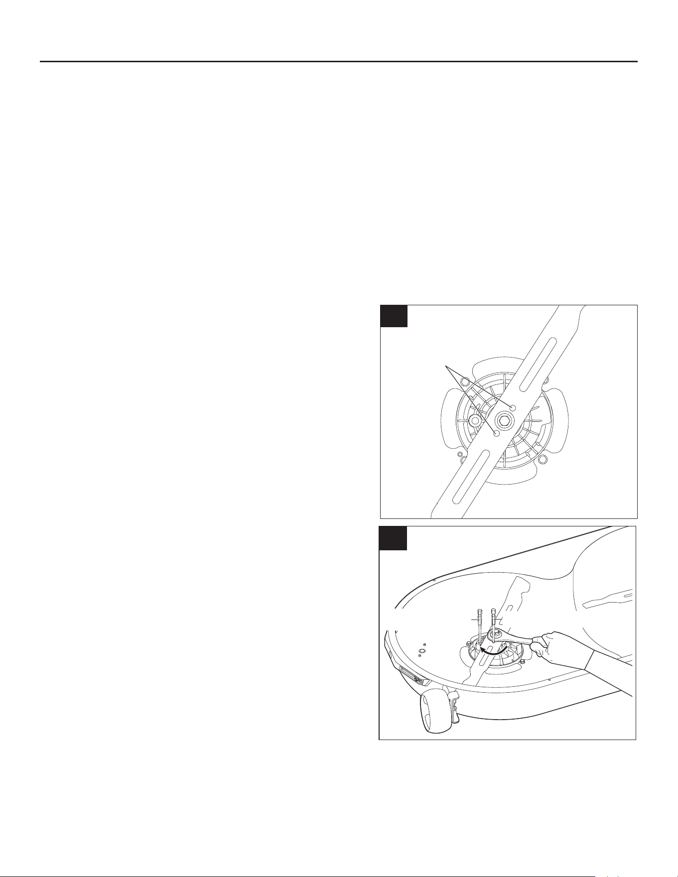
117
CUIDADO Y MANTENIMIENTO
d. Mientras usa guantes protectores, coloque un destornillador o una varilla de metal de 8 mm (5/16
pulg.) o un poco menos de diámetro en el oricio de jación del motor para que actúe como
estabilizador 1. Coloque otro destornillador o varilla de metal de 6.35 mm (1/4 pulg.) o un poco
menos de diámetro (por ejemplo, una broca) en el oricio alineado de la cuchilla y el reborde para
actuar como estabilizador 2 (Fig. 24a).
e. Use una llave inglesa de 14 mm (9/16 pulg.) (no incluida) para girar el perno de la cuchilla en
dirección contraria a las manecillas del reloj para aojarlo (Fig. 24a).
f. Mientras usa guantes protectores, retire el perno, la arandela y la cuchilla (Fig. 24b). El reborde
puede permanecer en el eje del motor.
Para instalar la cuchilla de corte
AVISO: Para reinstalar las cuchillas o reemplazarlas, asegúrese de volver a colocar todas las piezas
en el orden exacto en que se retiraron (Fig. 24b).
a. Si se retira el reborde durante la extracción de la
cuchilla, alinéelo primero con el eje del motor y,
luego, ensámblelo en su lugar.
b. Mientras usa guantes protectores, coloque la cuchilla
en el reborde con la supercie que indica “ESTE
LADO ORIENTADO AL CÉSPED” hacia el exterior
(Fig. 25a).
c. Alinee la arandela con el eje del motor y móntela en
el eje del motor.
d. Monte el perno en el eje del motor. Apriete el perno
con la mano en dirección de las manecillas del reloj.
e. Mueva la cuchilla con la mano y alinee los dos
oricios de la cuchilla con los dos oricios del
reborde (Fig. 25a).
f. Coloque un destornillador o varilla de metal de 6.35
mm (1/4 pulg.) o un poco menos de diámetro (p.
ej., una broca) en el oricio alineado de la cuchilla
y el reborde para que actúe como estabilizador 1.
Coloque otro destornillador o varilla de metal 8 mm
(5/16 pulg.) o un poco menos de diámetro en el
oricio de jación del motor para que actúe como
estabilizador 2 (Fig. 25b).
g. Utilice una llave de torque de 14 mm (9/16 pulg.)
para apretar el perno en dirección de las manecillas
del reloj. El torque recomendado para la tuerca de la
cuchilla es de 36 a 41 pies-libras (50-55 Nm).
h. Repita los pasos con la segunda cuchilla, si es
necesario.
i. Vuelva a ensamblar la plataforma en podadora como se indica en “QUITAR LA PLATAFORMA”
en este manual.
25b
Estabilizador 1
Estabilizador 2
THIS SIDE FACING GRASS
25a
Oricios
alineados
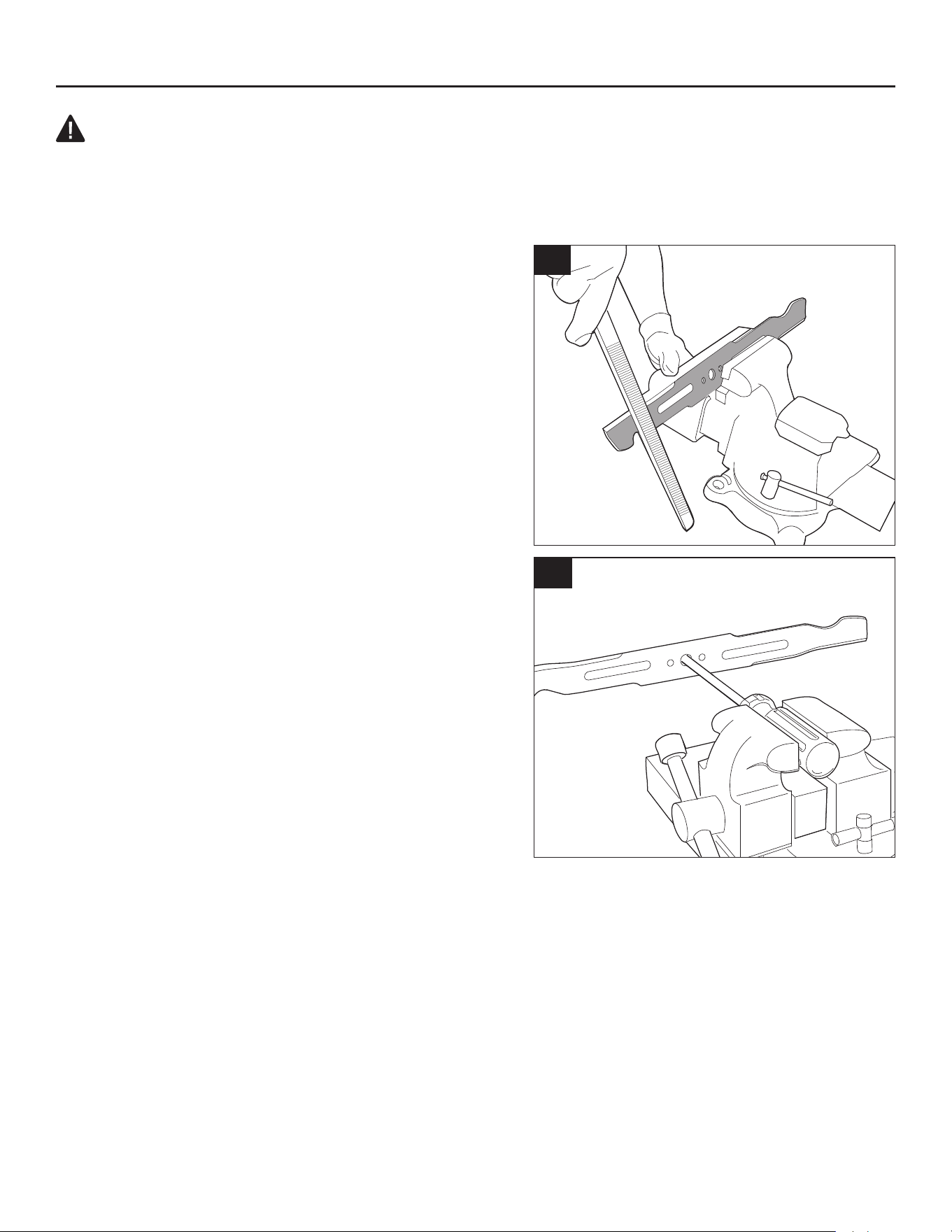
118
CUIDADO Y MANTENIMIENTO
ADVERTENCIA:
• Asegúrese de que la cuchilla esté correctamente colocada y que el perno de la cuchilla esté
apretado según las especicaciones de torsión anteriores. No jar correctamente la cuchilla podría
hacer que se suelte y provocar posibles lesiones personales graves.
AFILADO DE LAS CUCHILLAS DE CORTE
AVISO: Mantenga la cuchilla alada para obtener el
mejor rendimiento. Una cuchilla desalada no corta
el césped con precisión ni lo tritura adecuadamente.
Se puede alar una cuchilla desalada, pero se debe
reemplazar la cuchilla que esté muy desgastada,
doblada, agrietada o dañada. Una cuchilla desgastada
o dañada puede romperse y provocar que se
lancen pedazos de las cuchillas desde la podadora.
Si descubre que las cuchillas están dobladas,
comuníquese con el Servicio al Cliente de Kobalt
de inmediato. Nunca intente enderezar una cuchilla
doblada con calor ni soldar una cuchilla agrietada o
rota.
Frecuencia de alado
Alar la cuchilla de corte dos veces durante
una temporada de corte suele ser suciente en
circunstancias normales. La arena hace que la cuchilla
se desale rápidamente. Si el césped tiene suelo
arenoso, es posible que se requiera un alado más
frecuente.
Cuando se ala la cuchilla de corte:
a. Asegúrese de que la cuchilla permanezca equilibrada.
b. Ale la cuchilla de corte en el ángulo de corte original.
c. Ale los bordes de corte en ambos extremos de la
cuchilla y elimine una cantidad igual de material de cada extremo.
Alar la cuchilla en un tornillo de banco
a. Retire la cuchilla de la podadora (consulte la sección “Reemplazo de las cuchillas de corte” en
este manual).
b. Asegure la cuchilla en un tornillo de banco (Fig. 26a).
c. Use guantes y lentes de protección adecuados y tenga cuidado de no cortarse.
d. Lime cuidadosamente los bordes de corte de la cuchilla con una lima de dientes nos o una piedra
de alar. Mantenga el ángulo del borde de corte original.
26b
26a
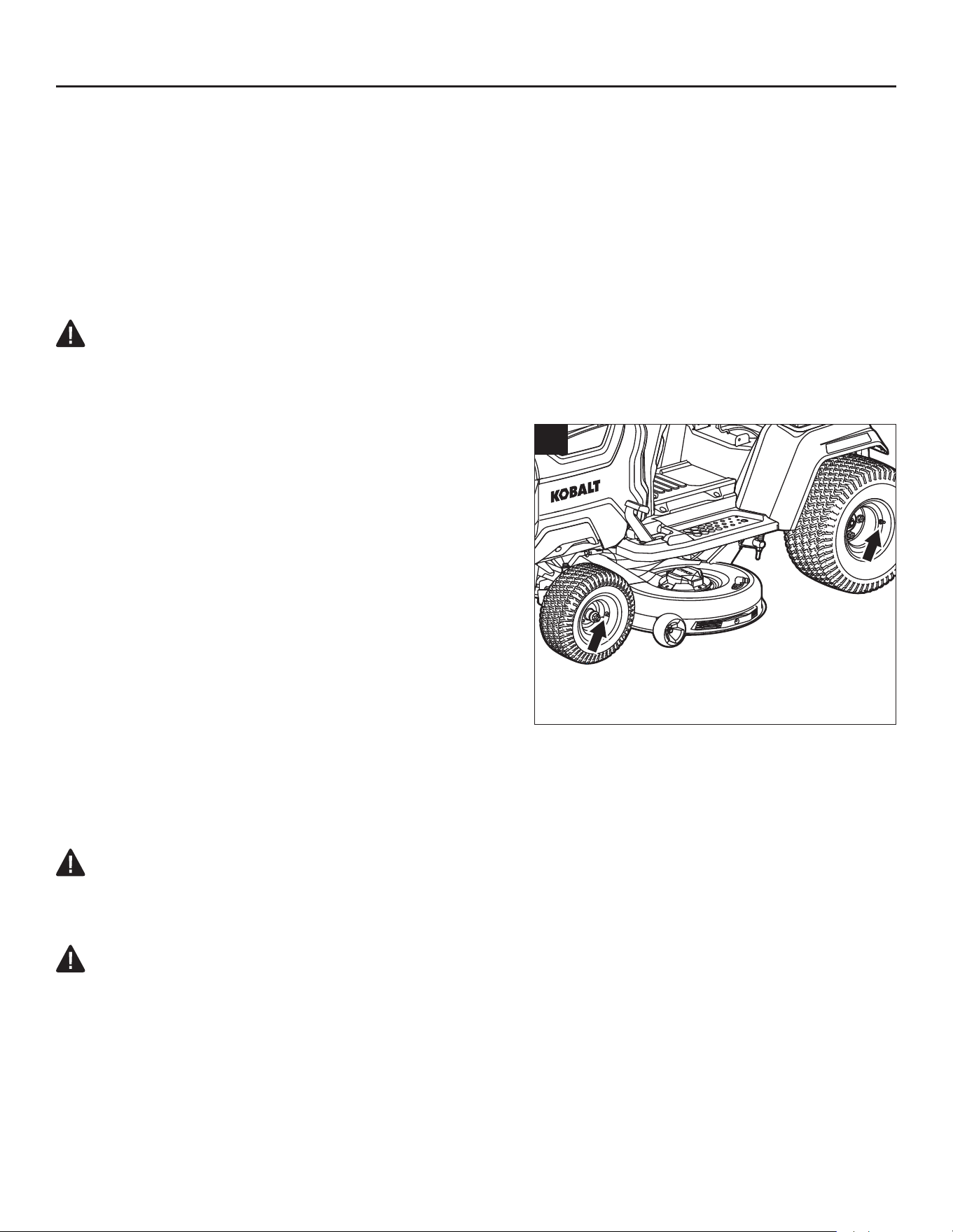
119
CUIDADO Y MANTENIMIENTO
e. Para comprobar el equilibrio de la cuchilla: sujete un clavo o un destornillador con un vástago
redondo en posición horizontal. Coloque la cuchilla de manera que el clavo o el vástago redondo del
destornillador soporte la cuchilla a través de su oricio central. Equilibre la cuchilla horizontalmente.
Si cualquiera de los extremos de la cuchilla gira hacia abajo, retire algo de metal del extremo pesado
(o inferior) hasta que la cuchilla esté equilibrada. La cuchilla está equilibrada cuando ninguno de los
extremos se va hacia abajo (Fig. 26b).
f. Vuelva a colocar la cuchilla y móntela rmemente en la podadora (consulte la sección “Reemplazo
de las cuchillas de corte” en este manual).
ADVERTENCIA:
• Una cuchilla desequilibrada provocará una vibración excesiva al girar a gran velocidad. Puede
causar daños a la podadora y podría romperse, lo que provocaría lesiones personales.
COMPROBAR LA PRESIÓN DE LOS NEUMÁTICOS
(Fig. 27)
Herramientas necesarias (no incluidas): medidor de
presión de los neumáticos; compresor de aire/inador o
bomba de aire para bicicleta de alta resistencia.
Verique la presión de aire en todos los neumáticos
antes de usarlos. Una presión de aire inadecuada
afectará el manejo, la respuesta de la dirección, la
tracción, la vida útil de los neumáticos, el nivel de corte
y la comodidad del operador. Asegúrese de que los
neumáticos estén inados a la presión que se muestra
en la Fig. 27.
Es importante para cortar el césped nivelado que
todos los neumáticos tengan la cantidad correcta de presión de aire. Si la podadora no avanza
en línea recta, verique primero la presión de aire de las ruedas.
AVISO: La presión de los neumáticos solo debe medirse o ajustarse cuando los neumáticos estén
“fríos” (la podadora aún no se ha conducido).
ADVERTENCIA:
• Compruebe la presión de los neumáticos cuidadosamente mientras los ina. Demasiado aire en el
neumático podría hacer que explote y provocar lesiones personales graves.
ADVERTENCIA:
• Mantener la presión de aire correcta en los neumáticos es muy importante. Muy poca presión
podría hacer que el neumático se salga de la llanta. Demasiada presión podría provocar que
el neumático explote. No mantener la presión de aire correcta en los neumáticos podría causar
problemas con el funcionamiento y la estabilidad de la podadora, y provocar lesiones personales
graves.
同A1机器图
27
14 PSI (96.5 kPa)
10 PSI
(68.9 kPa)
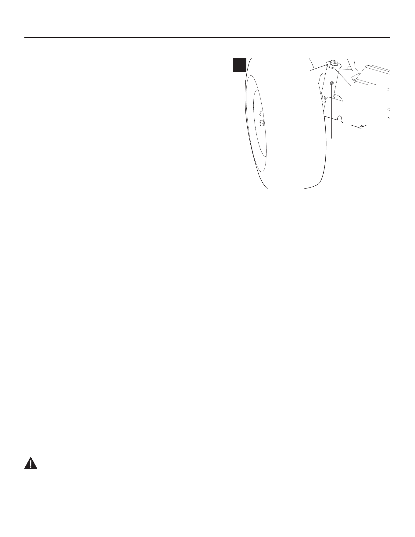
120
CUIDADO Y MANTENIMIENTO
LUBRICACIÓN DE LOS CASQUILLOS DE LOS EJES
DE LAS RUEDAS DELANTERAS (Fig. 28)
Herramientas necesarias (no incluidas): jeringa de
grasa.
Los engranajes de las ruedas delanteras deben
lubricarse de forma periódica con grasa para
engranajes. Si las ruedas delanteras de la podadora
cuando giran hacen un ruido anormal, retire la llave de
seguridad y, luego, llene los puertos de inyección con
grasa hasta que esta rebose el borde superior o inferior
de los casquillos de los ejes de las ruedas delanteras.
TRANSPORTE DE LA MÁQUINA (Fig. 29)
AVISO: no se recomienda remolcar la máquina directamente. Si es necesario, asegúrese siempre
de que las ruedas posteriores de la máquina estén levantadas del piso durante el remolcado. De lo
contrario, se podría dañar la máquina.
AVISO: Cuando se utiliza un montacargas, la máquina debe transportarse en el marco inferior en
todo momento. ¡El montacargas nunca debe entrar en contacto directo con la máquina!
Recomendamos conservar el marco inferior para facilitar el transporte posterior de la máquina para
su mantenimiento.
Consulte el capítulo “TRANSPORTE” más arriba en este manual para obtener instrucciones de
seguridad antes de transportar la máquina.
Equipamiento necesario (no incluido):
• Camioneta o remolque de tamaño completo con plataforma lo sucientemente grande como para
que quepa la máquina.
• 3 correas de amarre con trinquete.
• Cinta métrica.
• Cuerdas elásticas o soga.
• 2 personas.
• 2 rampas plegables para ATV de doble corredor con al menos 300 kg (661 libras) de capacidad
y 30.5 cm (12 pulgadas) de ancho. La longitud de la rampa está determinada por la altura de la
plataforma del camión/remolque sobre el suelo.
Por su seguridad, asegúrese de que la inclinación de las rampas sea inferior a 15° siempre que sea
posible.
ADVERTENCIA:
• Para reducir el riesgo de lesiones y daños materiales, NUNCA conduzca la máquina por la
rampa, hacia arriba o hacia abajo.
28
Borde
superior del
casquillo del
eje
Borde
inferior del
casquillo del
eje
Puerto de
inyección
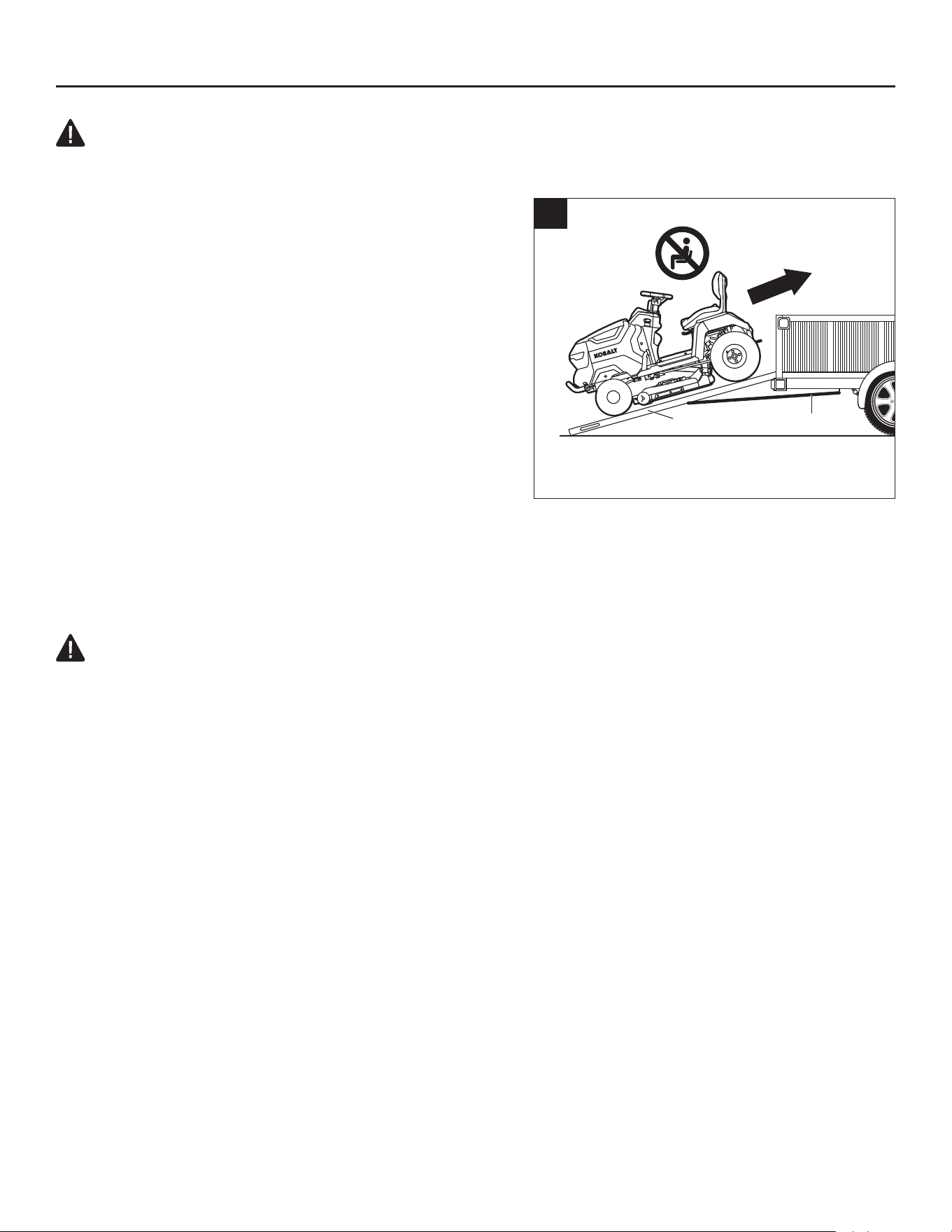
121
CUIDADO Y MANTENIMIENTO
ADVERTENCIA:
• Objeto pesado. Se necesitan dos personas para cargar/descargar la máquina.
Para cargar la máquina en un camión o remolque
a. Asegúrese de que su camión o remolque esté
estacionado en una supercie nivelada. La parte
trasera de la máquina debe mirar hacia la parte trasera
del camión/remolque.
b. Retire la llave de seguridad de la máquina.
c. Levante el conducto de descarga lateral y asegúrelo
en posición vertical con cuerdas elásticas o una soga.
d. Despliegue las rampas y alinee a simple vista la parte
inferior de cada rampa con el centro de la rueda
trasera correspondiente.
e. Utilice la cinta métrica para asegurarse de que los
extremos superiores de las rampas estén paralelos a
los extremos inferiores.
f. Conecte un extremo de la correa del trinquete al gancho de la cadena de seguridad del camión/
remolque. Conecte el otro extremo a la bisagra (o centro) de la rampa. Repita este paso con la otra
rampa.
g. Apriete las correas y asegúrese de que las rampas estén seguras y que no haya movimiento cuando
tire de las rampas o las correas.
ADVERTENCIA:
• Asegúrese siempre de que las rampas estén bien sujetas. Las rampas mal sujetas pueden
hacer que la máquina se caiga, lo que provocaría lesiones personales y daños graves.
h. Utilice la cinta métrica para vericar una vez más que las rampas estén paralelas.
i. Asegúrese de que el pedal del freno de mano de la máquina esté desactivado.
j. Cada persona debe colocar una mano en la carcasa de plástico cerca del panel de control y la
otra en el guardabarros trasero, y empujar la máquina hacia arriba por la rampa. NUNCA utilice el
volante, la palanca de ajuste de altura de la plataforma ni ninguna parte del asiento para empujar la
máquina.
k. Una vez que la máquina esté en la plataforma del camión/remolque, asegúrela en su lugar con las
correas de amarre. Una correa para asegurar la parte delantera de la máquina y las dos correas
restantes para asegurar el enganche.
l. Utilice el volante para girar las ruedas delanteras hacia la izquierda o hacia la derecha tanto como
sea posible.
m. Ponga el freno de mano.
Para descargar la máquina de un camión o remolque
a. Suelte las correas de amarre y quite el freno de mano.
b. Utilice el volante para girar las ruedas delanteras de modo que queden paralelas a la dirección de la
máquina.
c. Despliegue las rampas y alinee la parte superior de cada rampa con el centro de la rueda delantera
correspondiente.
29
Correas
Rampas

122
CUIDADO Y MANTENIMIENTO
d. Utilice la cinta métrica para asegurarse de que los extremos inferiores de las rampas estén paralelos
a los extremos superiores.
e. Conecte un extremo de la correa del trinquete al gancho de la cadena de seguridad del camión/
remolque. Conecte el otro extremo a la bisagra (o centro) de la rampa. Repita este paso con la otra
rampa.
f. Apriete las correas y asegúrese de que las rampas estén seguras y que no haya movimiento cuando
tire de las correas.
ADVERTENCIA:
• Asegúrese siempre de que las rampas estén bien sujetas. Las rampas mal sujetas pueden
hacer que la máquina se caiga, lo que provocaría lesiones personales y daños graves.
g. Utilice la cinta métrica para vericar una vez más que las rampas estén paralelas.
h. Cada persona debe colocar una mano en la carcasa de plástico cerca del panel de control y la otra
en el guardabarros trasero, y dirigir con cuidado la máquina por la rampa. NUNCA utilice el volante,
la palanca de ajuste de altura de la plataforma ni ninguna parte del asiento para empujar/apoyar la
máquina.
ALMACENAMIENTO
Debe seguir en orden los pasos a continuación antes de guardar la podadora.
• Cada seis meses de almacenamiento a largo plazo, cargue completamente la batería para obtener
la mayor duración posible.
• Retire la llave de seguridad de la podadora.
• Limpie completamente la podadora. Consulte la sección “MANTENIMIENTO GENERAL” de este
manual como referencia.
• Inspeccione la podadora en busca de piezas desgastadas o dañadas y apriete las tuercas o
tornillos que puedan haberse aojado.
• Almacene la podadora en un lugar limpio y seco. No la deje cerca de materiales corrosivos, como
fertilizantes o sal de roca.
• Almacene la podadora en un lugar cubierto, cerrado y fuera del alcance de los niños.
AVISO: Las cubiertas plásticas atrapan la humedad alrededor de la podadora, lo que produce óxido
y corrosión.

123
SOLUCIÓN DE PROBLEMAS
AVISO: Retire la llave de seguridad y, luego, vuelva a insertarla unos minutos más tarde para
reiniciar la podadora antes de realizar los procedimientos de solución de problemas.
PROBLEMA CAUSA SOLUCIÓN
La podadora no
avanza cuando se
pisa el pedal del
acelerador.
◾
El nivel de batería de la podadora
está bajo.
◾
Cargue la batería de la podadora.
◾
El pedal del freno de mano (K)
está puesto en la posición de freno
de mano.
◾
Pise a fondo el pedal del freno de
mano (K) para liberarlo de la posición
del freno de mano.
◾
El ícono del freno de mano (d)
parpadea en la pantalla LCD.
◾
Pise a fondo el pedal del freno de
mano (K), luego, suelte y presione
el pedal del acelerador (Q) para
conducir la podadora.
◾
El operador no está sentado en el
asiento.
◾
La podadora solo se puede
utilizar cuando el operador está
completamente sentado en el asiento.
◾ El sistema de bloqueo de
seguridad del asiento no está
conectado correctamente.
◾ Retire la llave de seguridad (EE) de
la podadora y levante el respaldo del
asiento para asegurarse de que el
enchufe del cable esté correctamente
conectado al enchufe situado en la
parte inferior del asiento (consulte el
capítulo “Instalación del asiento”).
Siga las instrucciones en “Arranque
de la podadora” para reiniciar la
podadora y ver si se puede arrancar.
De lo contrario, comuníquese con el
Servicio al Cliente de Kobalt y haga
que un técnico de servicio calicado
realice las reparaciones.
◾ En climas extremadamente
fríos, es posible que la función
de accionamiento no se inicie
de forma correcta debido a la
protección de baja temperatura.
◾ Almacene siempre la podadora de
césped en un ambiente cálido. Reinicie
la podadora cuando esté caliente. No
realice intentos repetidos en condiciones
de frío extremo, ya que podría dañar
la máquina. La temperatura de
funcionamiento recomendada es de 0 °C
a 40 °C (32 °F a 104 °F).
◾ La trayectoria de desplazamiento
del pedal del acelerador (Q) está
obstruida con residuos.
◾ Revise y retire la suciedad.
◾ Fallo de componentes mecánicos
o electrónicos del pedal del
acelerador (Q).
◾ Comuníquese con el Servicio al
Cliente de Kobalt y haga que un
técnico de servicio calicado realice
las reparaciones.
◾ La palanca de control de dirección
(D1) está en la posición “N”.
◾ Tire/empuje la palanca de control de
dirección (D1) en la dirección “D” o “R”.

124
PROBLEMA CAUSA SOLUCIÓN
La podadora deja
de moverse.
◾
Al cambiar entre avance y reversa
durante la conducción, la palanca
de control de dirección (D1)
permanece en la posición neutral
“N” durante mucho tiempo.
◾
Suelte el pedal del acelerador (Q) y,
luego, presiónelo de nuevo.
◾
Fallo de componentes electrónicos
del pedal del acelerador.
◾
Comuníquese con el Servicio al
Cliente de Kobalt y haga que un
técnico de servicio calicado realice
las reparaciones.
◾ El sistema de bloqueo de
seguridad del asiento se
desconectó durante la conducción
en terreno accidentado.
◾ Retire la llave de seguridad (EE) de
la podadora y levante el respaldo del
asiento para asegurarse de que el
enchufe del cable esté correctamente
conectado al enchufe situado en la
parte inferior del asiento (consulte el
capítulo “Instalación del asiento”).
Siga las instrucciones en “Arranque
de la podadora” para reiniciar la
podadora y ver si se puede arrancar.
De lo contrario, comuníquese con el
Servicio al Cliente de Kobalt y haga
que un técnico de servicio calicado
realice las reparaciones.
◾ El peso del operador no está
distribuido de forma uniforme
sobre el asiento. El peso del
operador en el asiento debe ser
de al menos 20 kg (44 libras)
para que el sistema de bloqueo
de seguridad del asiento funcione
correctamente.
◾ Siéntese correctamente en el asiento,
pise a fondo el pedal del freno de
mano (K) y suéltelo; la podadora
estará lista para circular.
SOLUCIÓN DE PROBLEMAS

125
PROBLEMA CAUSA SOLUCIÓN
Las cuchillas de la
podadora no arran-
can cuando se ac-
tiva el botón de ar-
ranque/apagado de
las cuchillas (G1).
El ícono de “cuchil-
las encendidas” (f)
en la pantalla LCD
y la luz del botón
de arranque/apaga-
do de las cuchillas
parpadean.
◾
El nivel de batería de la podadora
está bajo.
◾
Cargue la podadora.
◾
La podadora se sobrecarga en
el momento en que las cuchillas
empiezan a girar, lo que activa la
autoprotección de los motores de
las cuchillas.
◾
Primero, comience a cortar el césped
a una velocidad más baja de las
cuchillas y no acelere la velocidad de
las cuchillas hasta que estas giren
correctamente.
◾
En climas extremadamente fríos,
es posible que los motores de las
cuchillas no se inicien de forma
correcta debido a la protección de
baja temperatura.
◾
Almacene siempre la podadora
de césped en un ambiente cálido.
Reinicie la podadora cuando esté
caliente. No realice intentos repetidos
en condiciones de frío extremo,
ya que podría dañar la máquina.
La temperatura de funcionamiento
recomendada es de 0 °C a 40 °C
(32 °F a 104 °F).
◾
La cuchilla interere con la
plataforma de corte deformada.
◾
Llame al Servicio al Cliente de
Kobalt.
Las cuchillas de la
podadora no ar-
rancan cuando se
pulsa el botón de ar-
ranque/apagado de
las cuchillas (G1).
◾
Por razones de seguridad, las
cuchillas se apagarán al presionar
el botón de encendido/apagado
de las cuchillas durante más de 8
segundos.
◾
Presione el botón de encendido/
apagado de las cuchillas durante
más de 3 segundos, pero no más
de 8 segundos, para encender las
cuchillas.
SOLUCIÓN DE PROBLEMAS

126
PROBLEMA CAUSA SOLUCIÓN
Las cuchillas dejan
de girar durante el
corte de césped.
◾
La podadora está sobrecargada.
◾
Eleve la altura de corte de la
plataforma o reduzca la velocidad de
conducción para reducir la carga de
la podadora.
◾ La plataforma está obstruida con
césped y escombros.
◾ Limpie la plataforma y asegúrese de
que las cuchillas tengan libertad de
movimiento.
◾ Se sobrecalentaron los motores o
la batería de la podadora.
◾ Reduzca la carga de la podadora
al elevar la altura de corte de la
plataforma o disminuir la velocidad
de las cuchillas o de conducción, y
deje que los motores y la batería de
la podadora se enfríen.
◾ La podadora está en modo de bajo
consumo.
◾ Cuando la podadora está en modo de
bajo consumo, las cuchillas cambian
automáticamente a velocidad de
rotación baja. El operador debe dejar
de trabajar y conducir hasta la zona
de carga de baterías lo antes posible.
◾
Un objeto extraño golpea la
podadora, lo que provoca la
autoprotección del motor.
◾
Pulse el botón de encendido/
apagado de las cuchillas (G1) para
apagar los motores de las cuchillas
y, a continuación, pulse el botón de
encendido/apagado de las cuchillas
durante más de 3 segundos para
volver a ponerlos en marcha.
◾ La podadora se mueve en reversa,
y el ícono de corte en reversa (g)
no está iluminado en la pantalla
LCD.
◾ Apague los motores de las cuchillas y
reinícielos siguiendo las instrucciones
del apartado “Para activar (ingresar)
el corte en reversa”.
El indicador de
audio continúa
pitando.
◾
La podadora está en modo de bajo
consumo, y las cuchillas no están
apagadas.
◾
Presione el botón de encendido/
apagado de las cuchillas (G1) para
apagar los motores de las cuchillas.
El indicador de audio dejará de sonar
cuando se apaguen los motores de
las cuchillas.
◾
La podadora deja de avanzar
en una pendiente sin poner el
pedal del freno de mano en la
posición del freno de mano, o
deja de avanzar en una supercie
nivelada, el operador está fuera
del asiento sin poner el pedal del
freno de mano en la posición del
freno de mano.
◾
Ponga el pedal del freno de mano
(K) en la posición de freno de
mano cuando la podadora deje de
funcionar.
SOLUCIÓN DE PROBLEMAS

127
PROBLEMA CAUSA SOLUCIÓN
La luz del botón de
arranque/apagado
sigue iluminada
cuando la pan-
talla LCD se apaga
durante más de 10
segundos.
◾
La podadora no se apaga.
◾
Cargue la podadora y llame al
Servicio al Cliente de Kobalt para su
reparación inmediatamente.
La pantalla LCD
no se ilumina con
todos los íconos
encendidos.
◾
El botón de arranque/apagado
(E1) se ha presionado durante
menos de 3 segundos.
◾
La pantalla LCD solo mostrará el
“indicador de combustible” cuando
se presione brevemente el botón de
arranque/apagado.
◾
La pantalla LCD se encenderá
después de pisar a fondo el pedal
del freno de mano (K) y presionar
simultáneamente el botón de
arranque/apagado (E1) durante más
de 3 segundos.
◾
Cuando el ícono de la llave
de seguridad (b) parpadea en
la pantalla LCD, la llave de
seguridad (EE) no está puesta.
◾
Cuando el ícono del freno de
mano (d) parpadea en la pantalla
LCD, el pedal del freno de mano
(K) no está completamente
presionado.
◾
Introduzca la llave de seguridad (EE),
presione a fondo el pedal del freno
(K) y simultáneamente presione el
botón de arranque/apagado (E1)
durante más de 3 segundos para
prender la pantalla LCD.
La podadora
corta de manera
desigual, con una
diferencia de altura
signicativa de ade-
lante hacia atrás.
◾
Las aspas están desaladas.
◾
Ale o reemplace las cuchillas de
corte como se indica en este manual.
◾
Las cuchillas están dobladas.
◾
Reemplace las cuchillas de corte
dobladas siguiendo las instrucciones
del apartado “REEMPLAZO DE LAS
CUCHILLAS DE CORTE”.
◾
La plataforma no está nivelada, lo
que da como resultado diferentes
alturas de las cuchillas de corte.
◾
Nivele la plataforma siguiendo
las instrucciones del apartado
“NIVELACIÓN DE LA
PLATAFORMA”.
SOLUCIÓN DE PROBLEMAS

128
PROBLEMA CAUSA SOLUCIÓN
La altura de corte
de césped real no
coincide con la
altura declarada.
◾
Las tuercas de la plataforma del
varillaje de suspensión están
ojas.
◾
Siga las instrucciones del
apartado “NIVELACIÓN DE LA
PLATAFORMA” para realizar el
ajuste correcto de adelante hacia
atrás de la plataforma de corte y
apriete las cuatro tuercas en el
varillaje de suspensión (dos para
cada lado).
◾
La plataforma está dañada o
seriamente desgastada.
◾
Siga las instrucciones del apartado
“QUITAR LA PLATAFORMA” para
reemplazar la plataforma de corte.
La podadora no
tritura adecuada-
mente.
◾
Los recortes de césped húmedo
se pegan en el lado inferior de la
plataforma.
◾
Espere a que el césped se seque
antes de podar.
◾
La podadora está congurada
para cortar una gran cantidad de
césped de una sola vez.
◾
Aumente la altura de corte de la
plataforma.
Vibración excesiva.
◾
Las cuchillas de corte están
sueltas.
◾
Apriete el perno de la cuchilla al par
recomendado de 36 a 41 pies-libras
(50-55 Nm).
◾
Las cuchillas están dobladas.
◾
Reemplace las cuchillas de corte
dobladas siguiendo las instrucciones
del apartado “REEMPLAZO DE LAS
CUCHILLAS DE CORTE”.
◾
La plataforma no está nivelada.
◾
Nivele la plataforma de la podadora
siguiendo las instrucciones del
apartado “NIVELACIÓN DE LA
PLATAFORMA”.
◾
Las tuercas de la plataforma del
varillaje de suspensión están
ojas.
◾
Utilice una llave española de 18
mm (23/32 pulg.) (no incluida) para
apretar las cuatro tuercas del varillaje
de suspensión (dos para cada lado).
◾
La plataforma está congurada
para cortar una gran cantidad de
césped de una sola vez.
◾
Aumente la altura de corte de la
plataforma.
SOLUCIÓN DE PROBLEMAS

129
SOLUCIÓN DE PROBLEMAS
PROBLEMA CAUSA SOLUCIÓN
Queda césped o
escombros en el
suelo después de
cortar el césped.
◾
La plataforma está congurada
para cortar demasiado césped a la
vez cuando el césped está alto.
◾
Comience con una altura de corte
alta y redúzcala hasta lograr el
resultado de corte deseado. El
césped de más de 152 mm (6 pulg.)
de alto se debe cortar dos veces, a
alturas de corte sucesivamente más
bajas.
◾
El césped está mojado.
◾
No corte cuando el césped esté
mojado. Espere hasta que el césped
se seque.
◾
La velocidad de conducción es
alta.
◾
Reduzca la velocidad de conducción.
◾
La velocidad de las cuchillas es
baja.
◾
Aumente gradualmente la velocidad
de las cuchillas.
Corto tiempo de
funcionamiento de
la podadora.
◾
El terreno del césped, las
condiciones del césped, el ajuste
de la altura de corte, la velocidad
de conducción, la velocidad
de las cuchillas, etc. afectarán
en gran medida el tiempo de
funcionamiento.
◾
Consulte el capítulo “Consejos
para aumentar el tiempo de
funcionamiento” para obtener
instrucciones.
La podadora no
avanza en línea
recta.
◾
La presión de los neumáticos de
las ruedas de la izquierda y la
derecha son diferentes.
◾
Verique y ajuste la presión de aire
en los neumáticos de las ruedas
delanteras y traseras, de acuerdo
con la sección “COMPROBAR LA
PRESIÓN DE LOS NEUMÁTICOS”
de este manual.
◾
El volante no está instalado
correctamente.
◾
Verique y asegúrese de que el
volante esté instalado correctamente
de acuerdo con la sección
“Instalación del asiento” de este
manual.
El pedal del freno
de mano no puede
soltarse de la
posición de frenado
o tarda en retro-
ceder.
◾
La trayectoria de desplazamiento
del pedal del freno de mano (K)
está obstruida con residuos.
◾
Revise y retire la suciedad.

130
PROBLEMA CAUSA SOLUCIÓN
La podadora no
se puede cargar a
través del puerto
de carga.
◾
El enchufe del cargador no
está insertado correctamente
en el puerto de carga (J) de la
podadora.
◾
Vuelva a conectar el enchufe del
cargador para ver si la podadora se
puede cargar normalmente.
◾
No hay electricidad en los
enchufes de la pared.
◾
No es necesaria ninguna acción.
Espera a que se recupere la
corriente.
◾
Mal funcionamiento del cargador.
◾
Comuníquese con el Servicio
al Cliente de Kobalt y haga que
un técnico de servicio calicado
inspeccione o repare el cargador, si
es necesario.
◾
El puerto de carga (J) de la
podadora está defectuoso.
◾
Comuníquese con el Servicio al
Cliente de Kobalt y haga que un
técnico de servicio calicado realice
las reparaciones.
La podadora no
se puede arrancar
después de la lim-
pieza.
◾
Limpieza inadecuada, como que
entre agua en los componentes
eléctricos, en la pantalla LCD, etc.
◾
Siga las instrucciones del apartado
“MANTENIMIENTO GENERAL” para
limpiar correctamente la podadora.
◾
La podadora quedó atrapada
accidentalmente bajo la lluvia.
◾
Deje secar la podadora durante más
de 12 horas o utilice aire comprimido
para secarla.
La plataforma se
obstruye rápida-
mente.
◾
La plataforma no se limpió
adecuadamente después de un
uso anterior.
◾
Limpie la plataforma de corte
después de cada uso, siguiendo la
sección “Uso del puerto de lavado
para limpiar la plataforma”.
La podadora pierde
tracción fácilmente
al subir una pen-
diente.
◾
Los neumáticos de las ruedas
traseras están desgastados.
◾
Comuníquese con el Servicio
al Cliente de Kobalt y haga que
un técnico de servicio calicado
sustituya las ruedas/neumáticos.
◾
Cortar en una pendiente
pronunciada.
◾
La podadora no debe utilizarse para
cortar en pendientes de más de 15
grados.
Cuando la podadora
se detiene en una
pendiente con el
pedal del freno de
mano (K) puesto, la
podadora puede ro-
dar pendiente abajo.
◾
Los componentes del freno están
muy desgastados debido a un
funcionamiento inadecuado de la
podadora.
◾
Comuníquese con el Servicio al
Cliente de Kobalt y haga que un
técnico de servicio calicado realice
las reparaciones.
SOLUCIÓN DE PROBLEMAS

131
PROBLEMA CAUSA SOLUCIÓN
No sale agua del
puerto de lavado
cuando se intenta
lavar la plataforma.
◾
El acoplador rápido del puerto
de lavado (FF) no está montado
correctamente en el puerto de
lavado.
◾
Vuelva a conectar el acoplador rápido
del puerto de lavado (FF) hasta que
escuche un “clic” claro después
de empujar rmemente. Si eso no
resuelve el problema, comuníquese
con el Servicio al Cliente de Kobalt.
Se escucha un
sonido anormal al
empujar manual-
mente la podadora
sin arrancarla.
◾
El sonido proviene de los imanes
dentro del motor impulsor.
◾
Es normal y no es necesario realizar
ninguna acción.
El volante (V) no se
puede girar.
◾
El conjunto del volante está
obstruido con escombros.
◾
Revise y retire la suciedad.
La podadora no gira
hacia la izquierda
o hacia la derecha
cuando se gira el
volante (V).
◾
Fallo de componentes electrónicos
o mecánicos.
◾
Comuníquese con el Servicio al
Cliente de Kobalt y haga que un
técnico de servicio calicado realice
las reparaciones.
La podadora no se
detiene al soltar el
pedal del acelerador
(Q).
◾
La trayectoria de retorno del pedal
del acelerador (Q) está obstruida
con residuos.
◾
Revise y retire la suciedad.
◾
El botón CCS (J1) se presiona
de forma involuntaria mientras se
conduce. La podadora está en
modo de control de crucero.
◾
Verique si el ícono CCS (a) está
iluminado en la pantalla LCD y
salga del CCS según sea necesario.
Consulte el capítulo “Uso del control
de crucero (CCS)”.
La función CCS no
se puede activar ni
desactivar.
◾
El botón CCS (J1) no está
presionado correctamente.
◾
Presione el botón CCS (J1) hasta
que el ícono CCS (a) se ilumine en la
pantalla LCD o desaparezca de ella.
◾
La velocidad de conducción es
demasiado baja para activar la
función CCS.
◾
Aumente la velocidad de conducción
y active nuevamente la función CCS.
SOLUCIÓN DE PROBLEMAS
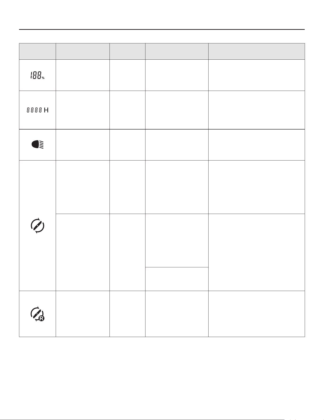
132
ÍCONOS Y CÓDIGOS DE FALLA EN LA PANTALLA LCD
Pantalla
LCD
Descripción
Indicador
de audio
Causa Solución
El indicador de
combustible (q)
se ilumina en la
pantalla LCD.
No
Indica la carga de la
batería de la poda-
dora.
Esto es normal. No es necesaria
ninguna acción.
El contador de
horas (o) se
ilumina en la
pantalla LCD.
No
Muestra el tiempo
total de conducción
de la podadora en
horas y no se puede
restablecer.
Esto es normal. No es necesaria
ninguna acción.
El ícono de los
faros LED (e)
se ilumina en la
pantalla LCD.
No
Los faros se encien-
den mediante el
interruptor de faros
LED.
Esto es normal. No es necesaria
ninguna acción.
El ícono "Cuchil-
las encendidas”
(f) se ilumina en
la pantalla LCD.
No
Las cuchillas se
encienden tras
pulsar el botón de
encendido/apagado
de cuchillas (G1)
durante más de 3
segundos.
Esto es normal. No es necesaria
ninguna acción.
El ícono “Cuchil-
las encendidas”
(f) parpadea en
la pantalla LCD.
No
Las cuchillas no se
encendieron tras
pulsar el botón de
encendido/apagado
de cuchillas (G1)
durante más de 3
segundos.
Compruebe si la podadora está
sobrecargada o si la carga de la
batería es baja.
O reinicie la podadora y vuelva
a encender las cuchillas. Si aún
falla, comuníquese con el Servi-
cio al Cliente de Kobalt.
Se interrumpe el
funcionamiento de
las cuchillas.
El ícono de cor-
tar en reversa (g)
se ilumina en la
pantalla LCD.
No
Indica que las
cuchillas se pueden
encender cuando la
podadora se mueve
en reversa.
Esto es normal. Si es necesario,
apague las cuchillas mientras
conduce en reversa siguiendo
la sección “Para detener (salir)
del corte en reversa” en el
manual.
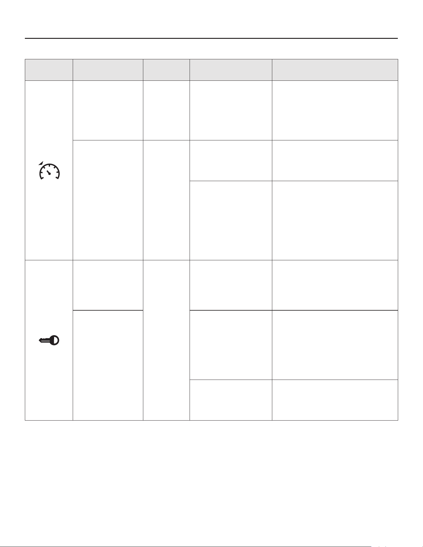
133
Pantalla
LCD
Descripción
Indicador
de audio
Causa Solución
El ícono CCS (a)
se ilumina en la
pantalla LCD
No
La podadora avanza
a una velocidad
determinada sin
necesidad de pisar
el pedal del acelera-
dor.
Esto es normal. Si es necesario,
apague la función CCS siguien-
do la sección “Para detener
(salir) del control de crucero
(CCS)” en el manual.
El ícono CCS (a)
parpadea en la
pantalla LCD.
No
La función CCS
(sistema de control
de crucero) ha fa-
llado.
La función CCS no se puede
congurar cuando la podadora
circula a muy baja velocidad o
en reversa.
Se pisa el pedal
del freno de mano
(K) para detener la
podadora.
Después de soltar el pedal del
freno de mano, presione el
botón CCS y el ícono CCS se
iluminará en la pantalla LCD, o
salga de la función CCS siguien-
do las instrucciones de la sec-
ción “Para detener (salir) del
control de crucero (CCS)”.
El ícono de la
llave de se-
guridad (b) se
ilumina en la
pantalla LCD.
No
La llave de se-
guridad (EE) está
insertada correcta-
mente.
Esto es normal. No es necesaria
ninguna acción.
El ícono de la
llave de seguri-
dad (b) parpadea
cuando la pan-
talla LCD mues-
tra el “indicador
de combustible”.
La llave de seguri-
dad (EE) no está
insertada.
Introduzca la llave de seguridad
(EE), pise a fondo el pedal del
freno de mano y pulse simul-
táneamente el botón de arran-
que/apagado (E1) durante más
de 3 segundos para encender la
podadora.
El panel de control
de la llave de seguri-
dad está dañado.
Comuníquese con el Servicio
al Cliente de Kobalt y haga que
un técnico de servicio calicado
realice las reparaciones.
ÍCONOS Y CÓDIGOS DE FALLA EN LA PANTALLA LCD

134
Pantalla
LCD
Descripción
Indicador
de audio
Causa Solución
El ícono del freno
de mano (d) se
ilumina en la
pantalla LCD.
No
El pedal del freno de
mano (K) está pues-
to en la posición de
freno de mano.
Suéltelo antes de arrancar la
podadora.
El ícono del freno
de mano (d)
parpadea cuan-
do la pantalla
LCD muestra
el “indicador de
combustible”.
No
El pedal del freno
de mano (K) no está
pisado.
Con la llave de seguridad (EE)
puesta, pise a fondo el pedal
del freno de mano y pulse
simultáneamente el botón de
arranque/apagado (E1) durante
más de 3 segundos para en-
cender la podadora.
El ícono del freno
de mano (d)
parpadea cuando
la pantalla LCD
muestra la inter-
faz del operador.
No
El operador aban-
dona el asiento y,
luego, vuelve a sen-
tarse para presionar
el pedal del acelera-
dor para conducir
la podadora de
césped.
Pise a fondo el pedal del freno
de mano (K) y, luego, suéltelo.
Luego, presione el pedal del
acelerador (Q) para conducir la
podadora.
Sigue
pitando
El pedal del freno de
mano no está pues-
to en la posición de
freno de mano.
El ícono del freno de mano (d)
se iluminará en la pantalla LCD,
y el indicador de audio dejará de
emitir un pitido tan pronto como
el pedal del freno (K) se coloque
en la posición de freno de mano.
El ícono del sen-
sor del asiento
(c) se ilumina en
la pantalla LCD.
No
El operador aban-
dona el asiento o
se desconecta el
sistema de bloqueo
de seguridad del
asiento.
Si el operador está sentado en
el asiento y el ícono está encen-
dido, deje de operar la podadora
de césped inmediatamente y
verique la conexión del asien-
to. Si se conrma la conexión
del asiento con la podadora,
comuníquese con el Servicio al
Cliente de Kobalt y haga que
un técnico de servicio calicado
realice las reparaciones.
ÍCONOS Y CÓDIGOS DE FALLA EN LA PANTALLA LCD
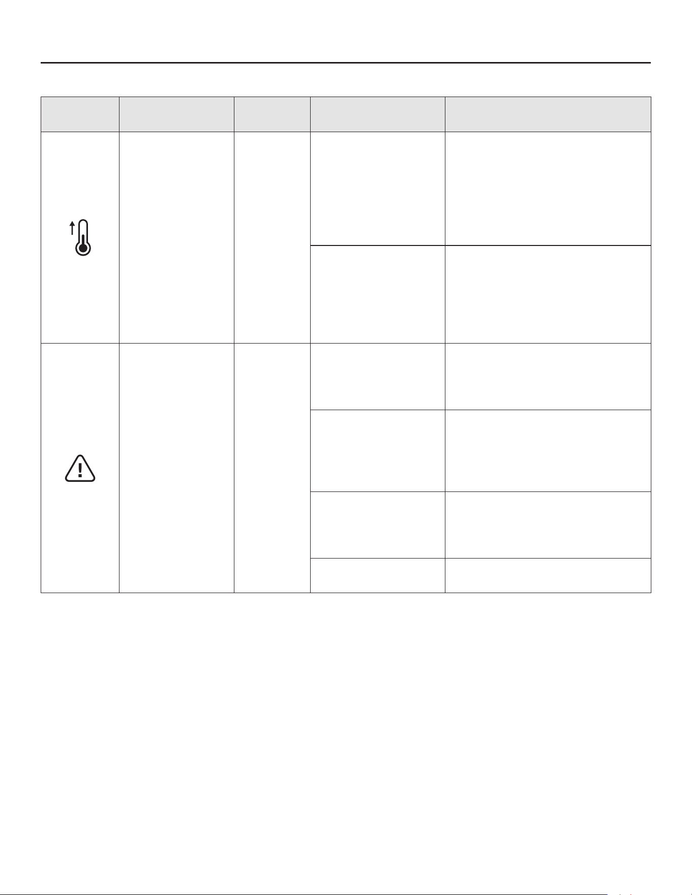
135
ÍCONOS Y CÓDIGOS DE FALLA EN LA PANTALLA LCD
Pantalla
LCD
Descripción
Indicador
de audio
Causa Solución
El ícono de
temperatura (j)
parpadea en la
pantalla LCD.
Un pitido
Se sobrecalentaron
los motores o la
bate ría de la poda-
dora.
Reduzca la carga de la poda-
dora al elevar la altura de corte
de la plataforma o disminuir la
velocidad de las cuchillas/con-
ducción. Tómese un descanso y
deje que se enfríen los motores
y la batería de la podadora.
Los motores o la
batería de la po-
dadora están muy
fríos.
No realice intentos repetidos
que puedan dañar la máquina.
Almacene siempre la podadora
de césped en un ambiente cáli-
do. Reinicie la podadora cuando
esté caliente.
El ícono de alerta
(i) parpadea en
la pantalla LCD.
Un pitido
Los motores de las
cuchillas están so-
brecargados.
Eleve la altura de corte de la
plataforma o reduzca la veloci-
dad de conducción para reducir
la carga de la podadora.
El conducto de
descarga lateral
está obstruido con
césped y escom-
bros.
Limpie el conducto de descarga
lateral después de cada uso.
Hay una interferen-
cia entre la cuchilla
y la plataforma de
corte.
Póngase en contacto con el Ser-
vicio al Cliente de Kobalt.
El motor está sobre-
cargado.
Verique y asegúrese de que las
ruedas giren libremente.

136
Pantalla
LCD
Descripción
Indicador
de audio
Causa Solución
El mensaje de
batería baja
parpadea en la
pantalla LCD.
Sigue
pitando
hasta que
se apagan
las cuchil-
las pre-
sionando
el botón de
encendido/
apagado
de las
cuchillas
(G1).
La batería tiene
poca carga, y la
podadora está en
modo de bajo con-
sumo.
Deje de trabajar y regrese a la
zona de carga de batería.
NOTA: Cuando la podadora está
en modo de bajo consumo, las
cuchillas cambian automática-
mente a velocidad de rotación
baja y, mientras tanto, el indica-
dor de audio seguirá emitiendo
un pitido. El operador debe
presionar el botón de encendido/
apagado de las cuchillas de
nuevo para apagar los motores
de las cuchillas. El indicador de
audio dejará de pitar después de
que las cuchillas se detengan.
Sigue
pitando
La batería está casi
agotada.
La podadora dejará de funcionar
inmediatamente. El operador
debe transportar la podadora a
la zona de carga de batería para
cargarla.
El indicador de
dirección de
avance (n) se
ilumina en la
pantalla LCD.
No
Indica que se puede
conducir la poda-
dora o que está
avanzando.
Esto es normal. Coloque la
palanca de control de dirección
en la posición “D”, “N” o “R”
según sea necesario.
El indicador de
dirección en
reversa (k) se
ilumina en la
pantalla LCD.
No
Indica que se puede
conducir la poda-
dora o que está en
reversa.
El indicador de
dirección neutral
(m) se ilumina en
la pantalla LCD.
No
Indica que no se
pudo conducir la
podadora.
El mensaje de
batería baja y el
código de falla (r)
“102” parpadean
en la pantalla
LCD.
Sigue
pitando
La batería está
agotada.
La podadora deja de funcionar.
El operador debe transportar la
podadora a la zona de carga de
batería para cargarla.
ÍCONOS Y CÓDIGOS DE FALLA EN LA PANTALLA LCD

137
Pantalla
LCD
Descripción
Indicador
de audio
Causa Solución
El ícono
”CHARGING”
(CARGANDO)
(p) y el indicador
de combustible
actual (q) se
iluminan en la
pantalla LCD.
Un pitido
Indica que la batería
de la podadora está
cargando.
Esto es normal. El icono
“CHARGING” (CARGANDO)
desaparecerá, y el indica-
dor de combustible mostrará
100 % cuan do la podadora esté
completamente cargada.
El ícono
”CHARGING”
(CARGANDO)
(p) y el ícono de
temperatura (j)
parpadean en la
pantalla LCD.
No
La batería de la
podadora se sobre-
calienta o está de-
masiado fría durante
la carga.
Espere hasta que la batería
vuelva a la temperatura normal.
Luego, la carga comenzará au-
tomáticamente.
El ícono
”CHARGING”
(CARGANDO)
(p) parpadea en
la pantalla LCD.
No
No se está cargando
correctamente la
podadora.
Cargue la podadora de césped
solo con el cargador especica-
do.
Falla en el cargador.
Compruebe si la autoinspección
del cargador puede activarse al
volver a enchufar el cargador o
al conectarlo a otro tomacorrien-
te. Si aún falla, comuníquese
con Servicio al Cliente de Ko-
balt.
El código de falla
(r) “509” parpa-
dea en la pan-
talla LCD.
Un pitido
El motor de la
cuchilla izquierda
falla al girar.
Inspeccione la cuchilla primero.
Si está oja, utilice una llave
dinamométrica de 14 mm (9/16
pulg.) (no incluida) para apretar
el perno en el sentido de las
manecillas del reloj. El torque
recomendado para la tuerca
de la cuchilla es de 36 a 41
pies-libras (50-55 Nm). De lo
contrario, comuníquese con el
centro de Servicio al Cliente y
haga que un técnico de servicio
calicado realice las reparacio-
nes.
El código de falla
(r) “609” parpa-
dea en la pan-
talla LCD.
Un pitido
El motor de la
cuchilla derecha
falla al girar.
NOTA: Para cualquier otro código de falla (r) que aparezca en la pantalla LCD, que pueda indicar
falla de PCBA, conexión suelta, falla del motor impulsor, motores de cuchillas, etc., retire la llave de
seguridad y vuelva a insertarla unos minutos más tarde para reiniciar la podadora. Si no se soluciona
el problema, comuníquese con el Servicio al Cliente de Kobalt y haga que un técnico de servicio
calicado realice las reparaciones.
ÍCONOS Y CÓDIGOS DE FALLA EN LA PANTALLA LCD

138
LISTA DE ACCESORIOS
PIEZA NÚMERO DEL MODELO NÚMERO DE ARTÍCULO
Kit de cuchillas de descarga (x2) KLMDB 1052-03 6505203
Kit de cuchillas de embolsado (x2) KLMB 1052-03 6505204
Clavija para compuesto orgánico KLMMP 1052-03 6505202
Kit de embolsadora para césped con mon-
taje de accesorios posterior
KLMGB 1052-03
6505201

139
GARANTÍA
El fabricante del producto proporciona la siguiente garantía limitada para la podadora Kobalt al com-
prador original de la podadora Kobalt.
El período de garantía detallado de cada podadora Kobalt se puede encontrar en línea en Lowes.
com. Póngase en contacto con Servicio al Cliente de Kobalt al número gratuito 1-888-3KOBALT
(888-356-2258) en cualquier momento que tenga preguntas o reclamos de garantía o desee una
copia impresa de la garantía.
GARANTÍA LIMITADA DE SERVICIO
La podadora Kobalt está garantizada contra defectos de material o mano de obra a partir de la fecha
de compra minorista original durante el período de garantía aplicable. Para cualquier reclamo de
garantía presentado de manera correcta y oportuna, si Lowe’s determina que un producto es defec-
tuoso durante el período de garantía, el producto recibirá reparación o reemplazo gratuito según lo
determine Lowe’s.
CÓMO OBTENER EL SERVICIO
Para obtener servicio de garantía, dentro del período de garantía aplicable, póngase en contacto con
el Servicio al Cliente de Kobalt al número gratuito 888-356-2258 (1-888-3KOBALT). Cuando pida un
servicio cubierto por la garantía, debe presentar el recibo con la fecha original de venta. Un centro de
servicio autorizado será seleccionado para evaluar y reparar el producto si está defectuoso de acu-
erdo con los términos establecidos en la garantía. Al llevar su producto al centro de servicio autor-
izado, es posible que se le solicite un pequeño depósito al entregar su herramienta. Este depósito es
reembolsable cuando se considera que el servicio de reparación cuenta con cobertura de la garantía.
El transporte de la podadora Kobalt es responsabilidad del comprador.
LIMITACIONES Y EXCLUSIONES ADICIONALES
Esta garantía limitada aplica solo al comprador original de Lowe’s y no es transferible. La podadora
Kobalt no se considerará defectuosa y esta garantía no se aplicará cuando el defecto reclamado sea
atribuible a cualquier causa distinta a los defectos denidos con anterioridad. Esta garantía se anu-
lará si el producto ha sido utilizado para propósitos de alquiler. Esta garantía no se aplicará a daños
causados por accidente, abuso, mal uso, alteración, modicación, reparación no autorizada, contacto
con líquidos, incendio, terremoto u otra causa externa; operación del producto fuera de las instruccio-
nes, especicaciones o pautas de la podadora Kobalt; o falta de servicio o mantenimiento adecuado
del producto. Esta garantía tampoco se aplica a daños cosméticos, incluidos, entre otros, rayones o
abolladuras; defectos causados por el uso y desgaste normal o debidos al envejecimiento normal del
producto.
Lowe’s Home Centers LLC.
MOORESVILLE, NC 28117
Impreso en China

