1.5 cu. ft. OTR Convection Microwave Oven
Installation Manual
Model: FMCM15-BL / FMCM15-SS
FMSMA15-BL / FMSMA15-SS
FMCM15-BL-A / FMCM15-SS-A
*
Picture shown here is for reference only.
https://furrion.com/
collections/cooking
* To view the multi-language user manual, please access the link or scan the QR code.
* Pour obtenir le manuel d’utilisateur multilingue, accédez au lien ou scannez le QR code.
* Para ver el manual de usuario en otros idiomas, acceda al siguiente enlace o escanee el código QR.

1
Table of Contents
Table of Contents ....................................................................................................................................... 1
Explanation of Symbols ............................................................................................................................ 2
Important Safety Instructions .................................................................................................................. 2
Before You Begin ...................................................................................................................................................................................................................2
Important Safety Instructions ...........................................................................................................................................................................................2
Electrical Requirements ......................................................................................................................................................................................................2
Shipment/Installation ...........................................................................................................................................................................................................3
Before Using ............................................................................................................................................... 3
Parts Included ..........................................................................................................................................................................................................................3
Tools You Will Need................................................................................................................................................................................................................3
Installation ..................................................................................................................................................4
Mounting Space ......................................................................................................................................................................................................................4
Placement of the Mounting Plate ....................................................................................................................................................................................4
Hood Exhaust ...........................................................................................................................................................................................................................6
Installation Types (Choose A, B or C) ............................................................................................................................................................................7
A. Recirculating (Non-Vented Ductless) Default (Fig. 10) ..................................................................................................................................... 7
B. Outside Top Exhaust (Vertical Duct) (Fig. 19) .......................................................................................................................................................9
C. Outside Back Exhaust (Horizontal Duct) (Fig. 36) .............................................................................................................................................12
2
Explanation of Symbols
This manual has safety information and instructions to help
you eliminate or reduce the risk of accidents and injuries.
Always respect all safety warnings identified with these
symbols. A signal word will identify safety messages and
property damage messages, and will indicate the degree or
level of hazard seriousness.
WARNING
Indicates a potentially hazardous situation which, if not
avoided, could result in death or serious injury.
CAUTION
Indicates a potentially hazardous situation which, if not
avoided, may result in minor or moderate personal injury, or
property damage.
DANGER
Indicates an imminently hazardous situation which, if not
avoided, will result in death or serious injury.
Important Safety Instructions
Before You Begin
Read these instructions completely and carefully.
● IMPORTANT – Save these instructions for local
inspector’s use.
● IMPORTANT – Observe all governing codes and
ordinances.
● Note to Installer – Be sure to leave these instructions with
the Consumer.
● Note to Consumer – Keep these instructions for future
reference.
● Skill level – Installation of this appliance requires basic
mechanical and electrical skills.
● Proper installation is the responsibility of the installer.
● Product failure due to improper installation is not covered
under the Warranty.
Important Safety Instructions
IMPORTANT – Please read carefully. For personal safety,
this appliance must be properly grounded to avoid severe or
fatal shock.
This product requires a three-prong, properly grounded outlet
for safe operation. If not properly grounded, or if the outlet box
does not meet electrical requirements noted (under Electrical
Requirements), a qualified electrician should be employed to
correct any deficiencies.
The power cord of this appliance is equipped
Ensure proper
ground exists
before use
with a three-prong (grounding) plug which
mates with a standard three-prong (grounding)
wall receptacle to minimize the possibility of
electric shock hazard from this appliance.
You should have the wall receptacle and
circuit checked by a qualified electrician
to make sure the receptacle is properly
grounded.
Where a standard two-prong wall receptacle is encountered,
it is very important to have it replaced with a properly
grounded three-prong wall receptacle, installed by a qualified
electrician.
Do not, under any circumstances, cut, deform or remove any
of the prongs from the power cord.
If a long cord or extension cord is used:
a) The marked electrical rating of the cord set or extension
cord should be at least as great as the electrical rating of
the appliance.
b) The extension cord must be a grounding-type 3-wire cord,
and the longer cord should be arranged so that it will not
drape over the counter top or table top where it can be
pulled on by children or tripped over unintentionally.
NOTE: For easier installation and personal safety, it is
recommended that two people install this product.
WARNING
For personal safety, remove the house fuse or turn off the
circuit breaker before beginning installation to avoid severe
or fatal shock injury.
For personal safety, the mounting surface
must be capable of supporting the
cabinet load, in addition to the added
weight of this 50-70 pounds (22.6-31.7
kilograms) product, plus additional oven
loads of up to 50 pounds (22.6 kilograms)
for a total weight of 100-120 pounds
(45.2-54.3 kilograms).
For personal safety, this product cannot
be installed in cabinet arrangements such as an island or a
peninsula. It must be mounted to BOTH a top cabinet AND a
wall.
Electrical Requirements
The product rating of your microwave is 120VAC / 60Hz
/ 15A max / 1500W. This product must be connected to a
supply circuit of the proper voltage and frequency. Wire size
must conform to the requirements of the National Electrical
Code or the prevailing local code for this kilowatt rating. The
power supply cord and plug should be brought to a separate
15 ampere branch circuit single grounded outlet. The outlet
box should be located in the cabinet above the microwave
oven. The outlet box and supply circuit should be installed by
a qualified electrician and conform to the National Electrical
Code or the prevailing local code.
Shipment/Installation
DAMAGE
● If the unit is damaged in shipment, return the unit to the store in which it was bought for repair or replacement.
● If the unit is damaged by the customer, repair or replacement is the responsibility of the customer.
● If the unit is damaged by the installer (if other than the customer), repair or replacement must be made by
arrangement between customer and installer.
Save these instructions for future reference
Before Using
1. Make sure the microwave oven has been installed
according to instructions.
2. Remove all packing material from the microwave oven.
3. Install turntable and ring in cavity.
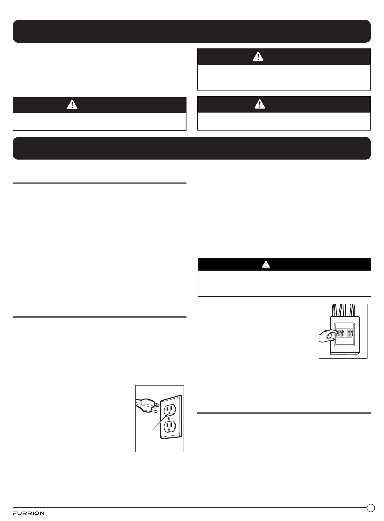
4. Replace house fuse or turn breaker back on. (Fig. A)
5. Plug power cord into a dedicated 15 amp electrical outlet.
(Fig. B)
6. Read the User Manual.
7. Keep installation manual for the local inspector’s use.
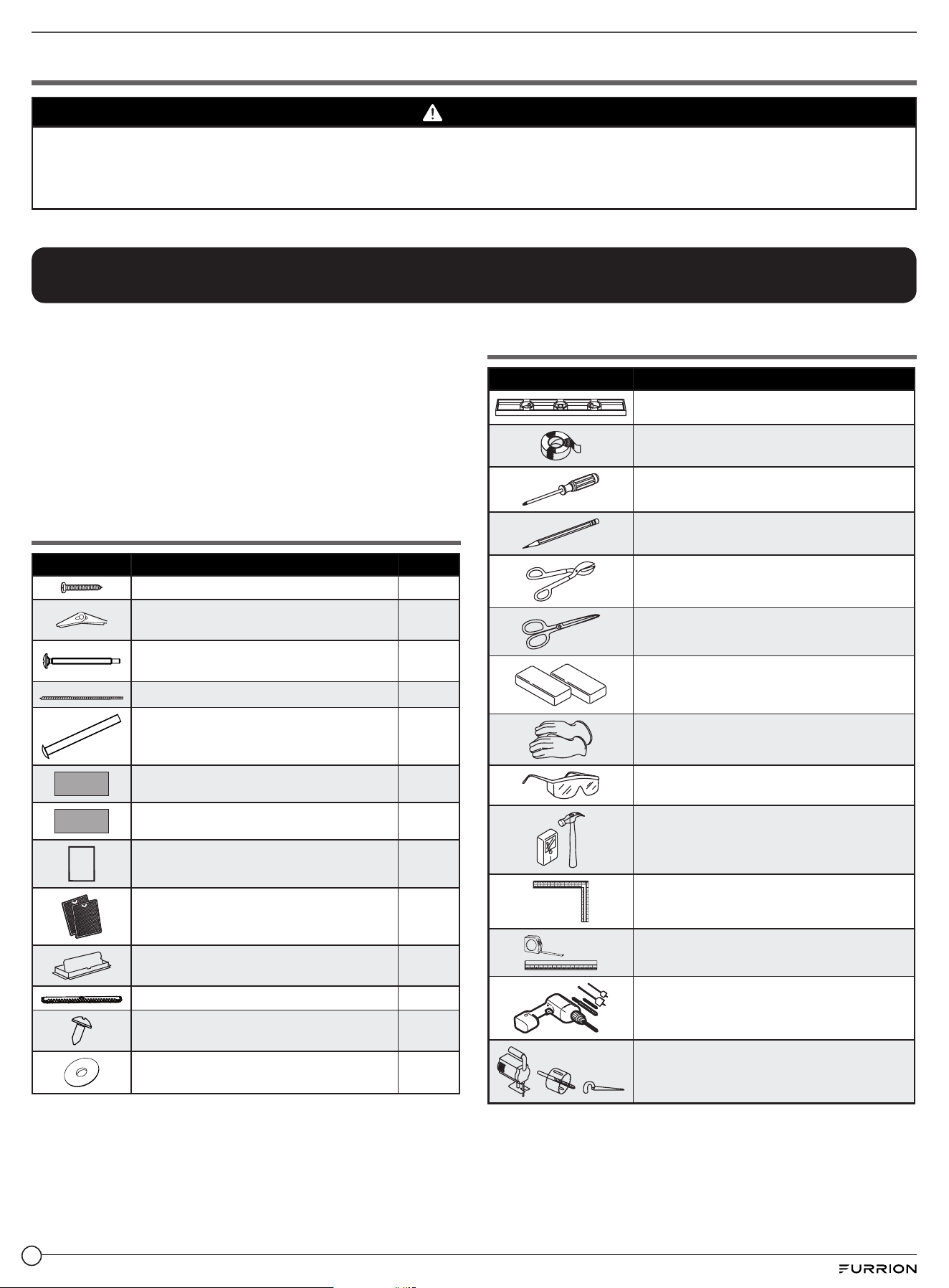
Parts Included
Part Description Quantity
Wood Screws (¼“ x 2“) 2
Wing Nut (match with 3/16" machine
screws)
2
Self-Aligning Machine Screws
(¼"-20 x 3“)
2
Nylon Grommet (for metal cabinets) 1
Machine Screws (3/16" x 3“) 2
Top Cabinet Template 1
Rear Wall Template 1
INS
TALL
ATION
INST
RUCTIONS
Installation Manual 1
Separately Packed Grease Filters 2
Exhaust adapter 1
Mounting-Plate 1
Sheet Metal Screw (3/16" x 5/16") 2
Washer (match with ¼" self-aligning
machine screws)
2
You will find the installation accessories contained in a packet
with the unit. Check to make sure you have all these parts.
NOTE: Some extra parts are included.
Tools You Will Need
Part Description
Level
Duct and masking tape
# 1 and #2 Phillips screwdriver
Pencil
Tin snips (for cutting damper, if required)
Scissors (to cut template, if necessary)
Filler blocks or scrap wood pieces, if
needed for top cabinet spacing (used on
recessed bottom cabinet installations only
Gloves
Safety goggles
Stud finder or Hammer (optional)
Carpenter square (optional)
Ruler or tape measure and straight edge
Electric drill with 3/16”, ½” and ⅝” drill bits
Saw (saber, hole or keyhole)
3
Installation
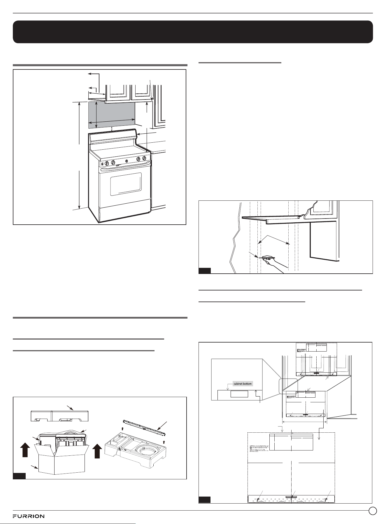
Mounting Space
Bottom edge of cabinet needs to
be 30” (76.2 cm) or more from the
cooking surface
Backsplash
66”(167.6 cm)
or more from
the floor to the
top of the
microwave
30” (76.2 cm)
2” (5.1 cm)
30”
(76.2 cm)
min.
16½" (41.9 cm)
In Exhaust Mode
(See Installation Types B & C on page 7):
Cabinet depth 15½" Maximum (39 cm)
In Recirculating Mode
(See Installation Types A on page 7):
Cabinet depth 13” Maximum (33 cm)
NOTE:
● The space between the cabinets must be 30” (76.2 cm)
wide and free of obstructions.
● If you are going to vent your microwave oven to the
outside, see Hood Exhaust Section for exhaust duct
preparation.
● When installing the microwave oven beneath smooth, flat
cabinets, be careful to follow the instructions on the top
cabinet template for power cord clearance.
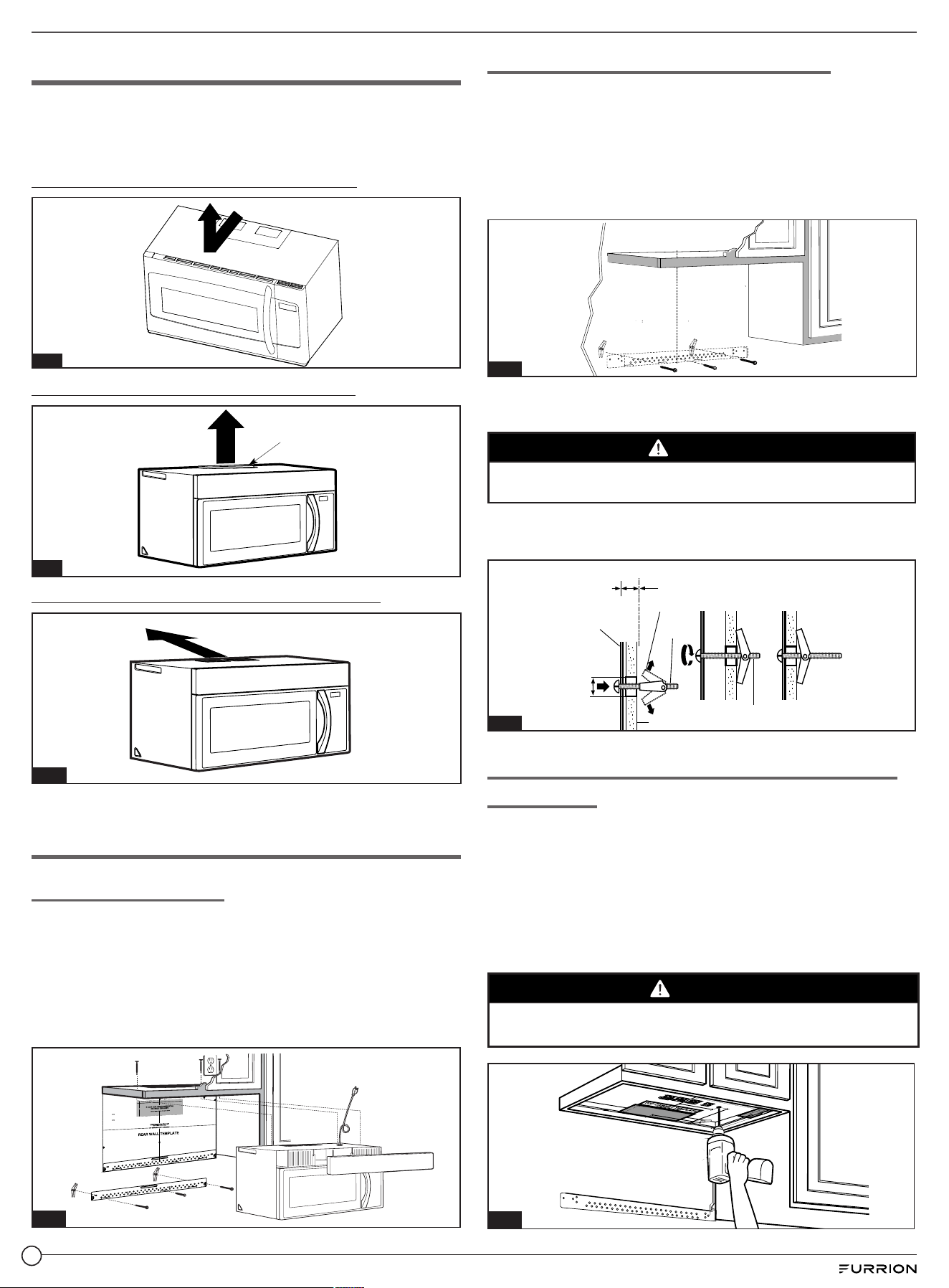
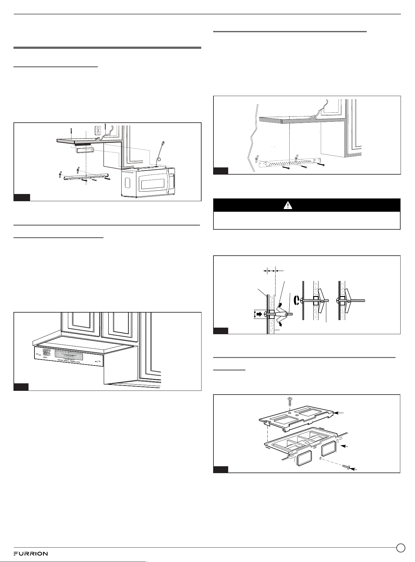
Placement of the Mounting Plate
Removing the Microwave Oven From the
Carton / Removing the Mounting Plate
1. Open the carton and remove the upper foam from the box,
but remember to keep the accessories.
2. Pull the oven out of the carton and remove the plastic bag
carefully.
3. Take the mounting plate out from the upper foam. (Fig. 1)
Upper Foam
Carton
Oven
Plastic Bag
Mounting Plate
Fig. 1
Finding the Wall Studs
1. Find the studs, using one of the following methods:
A. Wall stud finder – identifies the location of the vertical
wall studs.
NOTE: It can find nails but the primary function is to locate
the stud.
(OR)
B. Use a hammer to tap lightly across the mounting
surface to find a solid sound. This will indicate a wall stud
location.
2. After locating the stud(s), find the center by probing the
wall with a small nail to find the edges of the stud. Then
place a mark halfway between the edges. The center of
any adjacent studs should be 16” (40.6 cm) or 24” (61 cm)
from this mark.
3. Draw a line down the center of the studs. (Fig. 2)
NOTE: The microwave must be connected to at least one
wall stud.
Wall
Studs
Center
Fig. 2
Determining Top Line of Rear Wall Template
Location Under Your Cabinet
The bottom of the cabinet have three types:
1. Beneath flat bottom cabinet. (Fig. 3)
TOP LINE OF REAR WALL TEMPLATE must align with
cabinet bottom.
Front
Rear
F.CUT OUT FOR HORIZONTAL
OUTSI DE EXHAUST
CAUTION -IF EXHAUST ADAPTOR IS POSITIONED OUTSIDE
RECOMMENDED DIMENSION, GREASE-LADEN AIR WILL
DISCHARGE INTO HOUSE STRUCTURE
CUT HOLE THROUGH REAR WALL FOR EXHAUST ADAPTOR
NOTE: IT IS VERY IMPORTANT TO
READ AND FOLLLOW THE DIRECTIONS
IN THE INSTALLIONS INSTRUCTIONS
BEFORE PROCEEDING WITH THIS
REAR WALL TEMPLATE.
This template is for locating the horizontal exhaust
cutout .Do not use this temlate for vertical or
recirculation exhaust.
1.Tape the template to the rear wall.
2. Use a saber or keyhole saw to cut out the
shaded area F.through the rear wall.
3. Remove the template from the rear wall.
4. Return to and proceed with the installation
instructions.
12"
4"
K.CUT OUT FOR HORIZONTAL
OUTSIDE EXHAUST
⅜" TO EDGE
30" MINIMUM WIDTH REQUIRED
REAR WALL TEMPLATE
CAUTION -IF EXHAUST ADAPTOR IS POSITIONED OUTSIDE
RECOMMENDED DIMENSION,GREASE-LADEN AIR WILL
DISCHARGE INTO HOUSE STRUCTURE.
CUT HOLE THROUGH REAR WALL FOR EXHAUST ADAPTOR
NOTE:IT IS VERY IMPORTANT TO
READ AND FOLLOW THE DIRECTIONS
IN THE INSTALLATION INSTRUCTIONS
BEFORE PROCEEDING WITH THIS
REAR WALL TEMPLATE.
This Rear Wall Template serves to position the bottom
mounting plate and to locate the horizontal exhaust outlet.
1.Use a level to check that the template is positioned
accurately.
2.Locate and mark at least one stud on the left or right side
of the centerline.
Locate and mark holes to align with holes in the
mounting plate.
IMPROTANT:
LOCATE AT LEAST ONE STUD ON EITHER SIDE OF
THE CENTERLINE.
MARK THE LOCATION FOR 2 ADDITIONAL, EVENLY
SPACED TOGGLE BOLTS IN THE MOUNTING PLATE
AREA.
Trim the rear wall template along the dotted line.
A
C
B
6"
Min. 30” (76.2 cm)
12"
4"
K.CUT OUT FOR HORIZONTAL
OUTSIDE EXHAUST
3/8" TO EDGE
30" MINIMUM WIDTH REQUIRED
REAR WALL TEMPLATE
CAUTION -IF EXHAUST ADAPTOR IS POSITIONED OUTSIDE
RECOMMENDED DIMENSION,GREASE-LADEN AIR WILL
DISCHARGE INTO HOUSE STRUCTURE.
CUT HOLE THROUGH REAR WALL FOR EXHAUST ADAPTOR
NOTE:IT IS VERY IMPORTANT TO
READ AND FOLLOW THE DIRECTIONS
IN THE INSTALLATION INSTRUCTIONS
BEFORE PROCEEDING WITH THIS
REAR WALL TEMPLATE.
This Rear Wall Template serves to position the bottom
mounting plate and to locate the horizontal exhaust outlet.
1.Use a level to check that the template is positioned
accurately.
2.Locate and mark at least one stud on the left or right side
of the centerline.
Locate and mark holes to align with holes in the
mounting plate.
IMPROTANT:
LOCATE AT LEAST ONE STUD ON EITHER SIDE OF
THE CENTERLINE.
MARK THE LOCATION FOR 2 ADDITIONAL, EVENLY
SPACED TOGGLE BOLTS IN THE MOUNTING PLATE
AREA.
Trim the rear wall template along the dotted line.
A
C
B
6"
TOP LINE OF REAR WALL TEMPATE
TOP LINE OF REAR WALL TEMPATE
Fig. 3
4
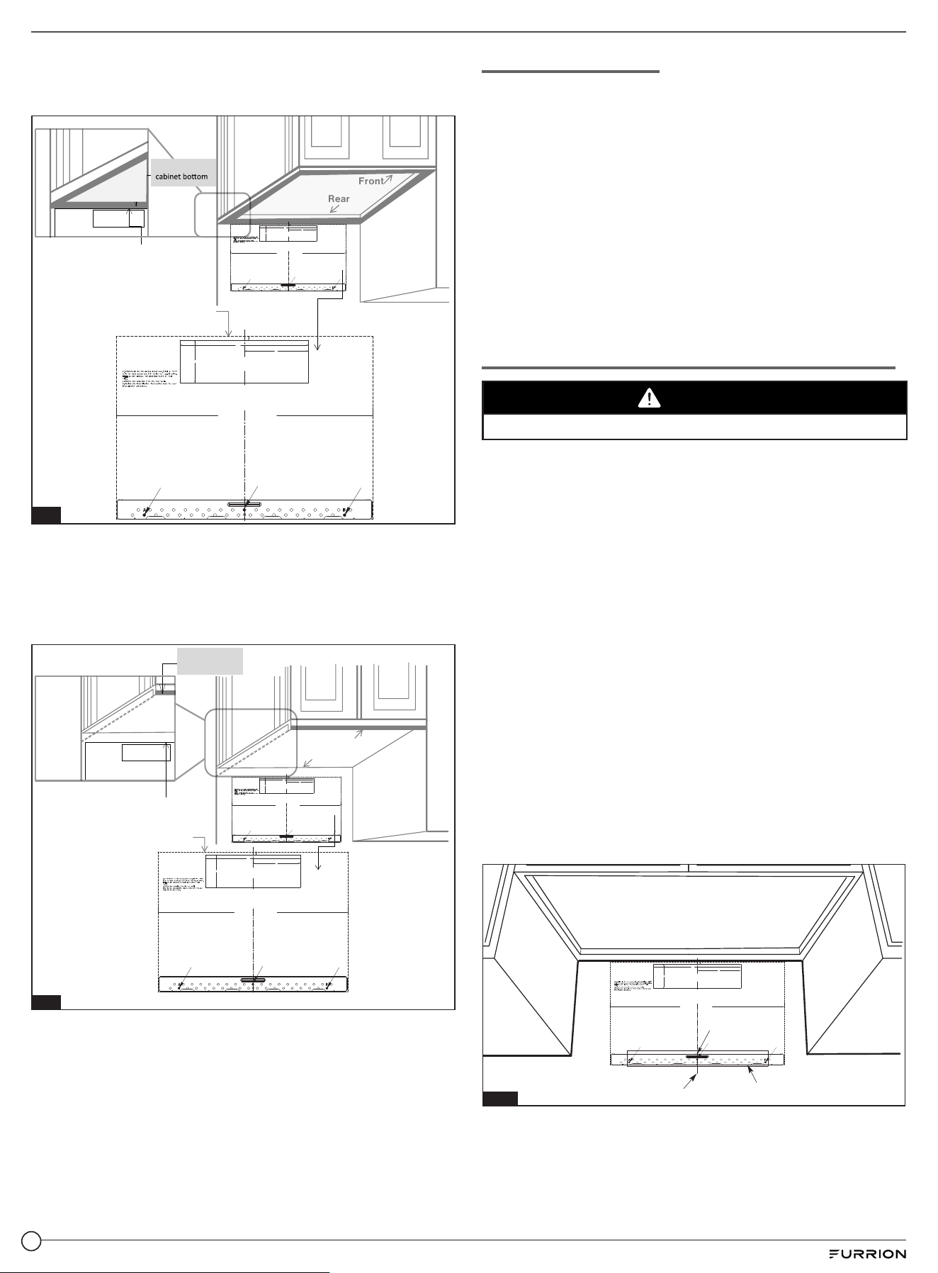
2. Beneath framed recessed cabinet (Fig. 4)
TOP LINE OF REAR WALL TEMPLATE must align with
the back frame of cabinet bottom.
F.CUT OUT FOR HORIZONTAL
OUTSI DE EXHAUST
CAUTION -IF EXHAUST ADAPTOR IS POSITIONED OUTSIDE
RECOMMENDED DIMENSION, GREASE-LADEN AIR WILL
DISCHARGE INTO HOUSE STRUCTURE
CUT HOLE THROUGH REAR WALL FOR EXHAUST ADAPTOR
TOP LINE OF REAR WALL TEMPATE
TOP LINE OF REAR WALL TEMPATE
Back frame of
Front
Rear
NOTE: IT IS VERY IMPORTANT TO
READ AND FOLLLOW THE DIRECTIONS
IN THE INSTALLIONS INSTRUCTIONS
BEFORE PROCEEDING WITH THIS
REAR WALL TEMPLATE.
This template is for locating the horizontal exhaust
cutout .Do not use this temlate for vertical or
recirculation exhaust.
1.Tape the template to the rear wall.
2. Use a saber or keyhole saw to cut out the
shaded area F.through the rear wall.
3. Remove the template from the rear wall.
4. Return to and proceed with the installation
instructions.
12"
4"
K.CUT OUT FOR HORIZONTAL
OUTSIDE EXHAUST
3/8" TO EDGE
30" MINIMUM WIDTH REQUIRED
REAR WALL TEMPLATE
CAUTION -IF EXHAUST ADAPTOR IS POSITIONED OUTSIDE
RECOMMENDED DIMENSION,GREASE-LADEN AIR WILL
DISCHARGE INTO HOUSE STRUCTURE.
CUT HOLE THROUGH REAR WALL FOR EXHAUST ADAPTOR
NOTE:IT IS VERY IMPORTANT TO
READ AND FOLLOW THE DIRECTIONS
IN THE INSTALLATION INSTRUCTIONS
BEFORE PROCEEDING WITH THIS
REAR WALL TEMPLATE.
This Rear Wall Template serves to position the bottom
mounting plate and to locate the horizontal exhaust outlet.
1.Use a level to check that the template is positioned
accurately.
2.Locate and mark at least one stud on the left or right side
of the centerline.
Locate and mark holes to align with holes in the
mounting plate.
IMPROTANT:
LOCATE AT LEAST ONE STUD ON EITHER SIDE OF
THE CENTERLINE.
MARK THE LOCATION FOR 2 ADDITIONAL, EVENLY
SPACED TOGGLE BOLTS IN THE MOUNTING PLATE
AREA.
Trim the rear wall template along the dotted line.
A
C
B
6"
12"
4"
K.CUT OUT FOR HORIZONTAL
OUTSIDE EXHAUST
3/8" TO EDGE
24" MINIMUM WIDTH REQUIRED
REAR WALL TEMPLATE
CAUTION -IF EXHAUST ADAPTOR IS POSITIONED OUTSIDE
RECOMMENDED DIMENSION,GREASE-LADEN AIR WILL
DISCHARGE INTO HOUSE STRUCTURE.
CUT HOLE THROUGH REAR WALL FOR EXHAUST ADAPTOR
NOTE:IT IS VERY IMPORTANT TO
READ AND FOLLOW THE DIRECTIONS
IN THE INSTALLATION INSTRUCTIONS
BEFORE PROCEEDING WITH THIS
REAR WALL TEMPLATE.
This Rear Wall Template serves to position the bottom
mounting plate and to locate the horizontal exhaust outlet.
1.Use a level to check that the template is positioned
accurately.
2.Locate and mark at least one stud on the left or right side
of the centerline.
Locate and mark holes to align with holes in the
mounting plate.
IMPROTANT:
LOCATE AT LEAST ONE STUD ON EITHER SIDE OF
THE CENTERLINE.
MARK THE LOCATION FOR 2 ADDITIONAL, EVENLY
SPACED TOGGLE BOLTS IN THE MOUNTING PLATE
AREA.
Trim the rear wall template along the dotted line.
A
C
B
6"
Fig. 4
3. Beneath framed recessed bottom cabinet with front
overhang (Fig. 5)
TOP LINE OF REAR WALL TEMPLATE must align with
below cabinet bottom the same distance as the front
overhang of cabinet bottom.
F.CUT OUT FOR HORIZONTAL
OUTSI DE EXHAUST
CAUTION -IF EXHAUST ADAPTOR IS POSITIONED OUTSIDE
RECOMMENDED DIMENSION, GREASE-LADEN AIR WILL
DISCHARGE INTO HOUSE STRUCTURE
Front overhang of
cabinet bottom
Front
Rear
CUT HOLE THROUGH REAR WALL FOR EXHAUST ADAPTOR
NOTE: IT IS VERY IMPORTANT TO
READ AND FOLLLOW THE DIRECTIONS
IN THE INSTALLIONS INSTRUCTIONS
BEFORE PROCEEDING WITH THIS
REAR WALL TEMPLATE.
This template is for locating the horizontal exhaust
cutout .Do not use this temlate for vertical or
recirculation exhaust.
1.Tape the template to the rear wall.
2. Use a saber or keyhole saw to cut out the
shaded area F.through the rear wall.
3. Remove the template from the rear wall.
4. Return to and proceed with the installation
instructions.
12"
4"
K.CUT OUT FOR HORIZONTAL
OUTSIDE EXHAUST
3/8" TO EDGE
30" MINIMUM WIDTH REQUIRED
REAR WALL TEMPLATE
CAUTION -IF EXHAUST ADAPTOR IS POSITIONED OUTSIDE
RECOMMENDED DIMENSION,GREASE-LADEN AIR WILL
DISCHARGE INTO HOUSE STRUCTURE.
CUT HOLE THROUGH REAR WALL FOR EXHAUST ADAPTOR
NOTE:IT IS VERY IMPORTANT TO
READ AND FOLLOW THE DIRECTIONS
IN THE INSTALLATION INSTRUCTIONS
BEFORE PROCEEDING WITH THIS
REAR WALL TEMPLATE.
This Rear Wall Template serves to position the bottom
mounting plate and to locate the horizontal exhaust outlet.
1.Use a level to check that the template is positioned
accurately.
2.Locate and mark at least one stud on the left or right side
of the centerline.
Locate and mark holes to align with holes in the
mounting plate.
IMPROTANT:
LOCATE AT LEAST ONE STUD ON EITHER SIDE OF
THE CENTERLINE.
MARK THE LOCATION FOR 2 ADDITIONAL, EVENLY
SPACED TOGGLE BOLTS IN THE MOUNTING PLATE
AREA.
Trim the rear wall template along the dotted line.
A
C B
6"
12"
4"
K.CUT OUT FOR HORIZONTAL
OUTSIDE EXHAUST
⅜" TO EDGE
30" MINIMUM WIDTH REQUIRED
REAR WALL TEMPLATE
CAUTION -IF EXHAUST ADAPTOR IS POSITIONED OUTSIDE
RECOMMENDED DIMENSION,GREASE-LADEN AIR WILL
DISCHARGE INTO HOUSE STRUCTURE.
CUT HOLE THROUGH REAR WALL FOR EXHAUST ADAPTOR
NOTE:IT IS VERY IMPORTANT TO
READ AND FOLLOW THE DIRECTIONS
IN THE INSTALLATION INSTRUCTIONS
BEFORE PROCEEDING WITH THIS
REAR WALL TEMPLATE.
This Rear Wall Template serves to position the bottom
mounting plate and to locate the horizontal exhaust outlet.
1.Use a level to check that the template is positioned
accurately.
2.Locate and mark at least one stud on the left or right side
of the centerline.
Locate and mark holes to align with holes in the
mounting plate.
IMPROTANT:
LOCATE AT LEAST ONE STUD ON EITHER SIDE OF
THE CENTERLINE.
MARK THE LOCATION FOR 2 ADDITIONAL, EVENLY
SPACED TOGGLE BOLTS IN THE MOUNTING PLATE
AREA.
Trim the rear wall template along the dotted line.
A
C
B
6"
TOP LINE OF REAR WALL TEMPATE
TOP LINE OF REAR WALL TEMPATE
Template must be at the same
distance below the cabinet bottom as
the FRONT EDGE OVERHANG.
Fig. 5
Your cabinets may have decorative trim that interferes with
the microwave installation. Remove the decorative trim to
install the microwave properly and to make it level.
Microwave Leveling
Use a level to make sure the cabinet bottom is level. If the
cabinets have a front overhang only, with no back or side
frame, top line of rear wall template must align with below
cabinet bottom, the same distance as the front overhang
depth. This will keep the microwave level.
1. Measure the inside depth of the front overhang.
2. Draw a horizontal line on the back wall an equal distance
below the cabinet bottom as the inside depth of the front
overhang.
3. For this type of installation with front overhang only, align
top line of rear wall template with this horizontal line, not
touching the cabinet bottom as described in “Aligning Top
Line of Rear Wall Template follows”.
Aligning Top Line of Rear Wall Template (Fig. 6)
CAUTION
Wear gloves to avoid cutting fingers on sharp edges.
1. Using a tape measure, draw a vertical line on the wall at
the center of the 30” (76.2cm) wide space.
2. Tape the rear wall template on the cabinet wall, align the
center markers on the rear wall template to the centerline
on wall, making sure it is level and that the top line of the
rear wall template is butted up against the bottom edge of
the upper cabinet.
3. According to the shape of cabinet, the location of the
wall template is compliant with the content part of
“Determining top line of rear wall template location under
your cabinet”.
4. While taping the rear wall template on the wall draw
circles on the wall at hole A,B,C (See Fig. 6 / actual plate
marked with arrows). THREE HOLES MUST BE USED
FOR MOUNTING. (If there are 2-wall studs in right and
left side based on center line Four hole must be used for
mounting)
5. Remove the rear wall template and check the marking
based on the actual mount plate (centerline, hole A,B,C).
6. Drill holes on the circle marks (A, B, C). Drill a 3/16” hole at C
for wood screw and two ⅝” holes at A, B for toggle bolts .
NOTE: DO NOT MOUNT THE PLATE AT THIS TIME.
Are a E
Center line
Cent r l ine notches
e
12"
4"
K.CUT OUT FOR HORIZONTAL
OUTSIDE EXHAUST
3/8" TO EDGE
30" MINIMUM WIDTH REQUIRED
REAR WALL TEMPLATE
CAUTION -IF EXHAUST ADAPTOR IS POSITIONED OUTSIDE
RECOMMENDED DIMENSION,GREASE-LADEN AIR WILL
DISCHARGE INTO HOUSE STRUCTURE.
CUT HOLE THROUGH REAR WALL FOR EXHAUST ADAPTOR
NOTE:IT IS VERY IMPORTANT TO
READ AND FOLLOW THE DIRECTIONS
IN THE INSTALLATION INSTRUCTIONS
BEFORE PROCEEDING WITH THIS
REAR WALL TEMPLATE.
This Rear Wall Template serves to position the bottom
mounting plate and to locate the horizontal exhaust outlet.
1.Use a level to check that the template is positioned
accurately.
2.Locate and mark at least one stud on the left or right side
of the centerline.
Locate and mark holes to align with holes in the
mounting plate.
IMPROTANT:
LOCATE AT LEAST ONE STUD ON EITHER SIDE OF
THE CENTERLINE.
MARK THE LOCATION FOR 2 ADDITIONAL, EVENLY
SPACED TOGGLE BOLTS IN THE MOUNTING PLATE
AREA.
Trim the rear wall template along the dotted line.
A
C
B
6"
Fig. 6
5
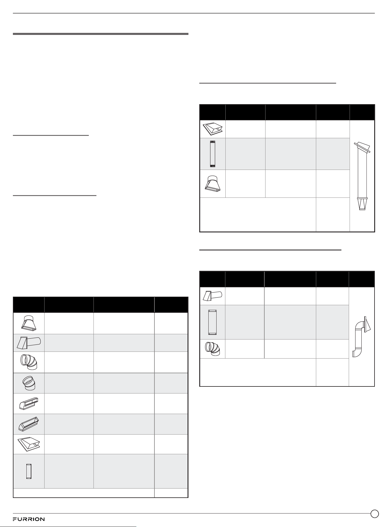
Hood Exhaust
NOTE: If you need to install ducting, note that the total duct
length of 3¼” x 10” (8.2 x 25.4cm) rectangular or 6”(15.2cm)
diameter round duct should not exceed 120 equivalent
feet (36.5m). Outside ventilation requires a HOOD
EXHAUST DUCT. Read the following carefully.
NOTE: It is important that venting be installed using the most
direct route and with as few elbows as possible. This ensures
clear venting of exhaust and helps prevent blockages. Also,
make sure dampers swing freely and nothing is blocking the
outlet or dampers.
Exhaust Connection
The exhaust adapter has been designed to mate with a
standard 3¼” x 10” (8.2 x 25.4cm) rectangular duct.
If a round duct is required, a rectangular-to-round transiting
adapter must be used. Do not use less than a 6” diameter
duct.
Maximum Duct Length
For satisfactory air movement, the total duct length of
3¼” x 10” (8.2 x 25.4 cm) rectangular or 6” (15.2 cm) diameter
round duct should not exceed 120 equivalent feet (36.5m).
Elbows, transitions, wall and roof caps, etc., present
additional resistance to airflow and are equivalent to a
section of straight duct which is longer than their actual
physical size. When calculating the total duct length, add the
equivalent lengths of all transitions and adapters plus the
length of all straight duct sections. The chart below shows
you how to calculate total equivalent ductwork length using
the approximate feet of equivalent length of some typical
ducts.
Part Description
Equivalent Length x
Number Used =
Equivalent
Duct Pieces
Rectangular-to-
Round
Transition Adapter*
5 Ft. (1.5 m) x =
Ft.
or m
Wall Cap 40 Ft. (12.2 m) x =
Ft.
or m
90° Elbow 10 Ft. (3 m) x =
Ft.
or m
45° Elbow 5 Ft. (1.5 m) x =
Ft.
or m
90° Elbow 25 Ft. (7.6 m) x = Ft. or m
45° Elbow 5 Ft. (1.5 m) x =
Ft.
or m
Roof Cap 24 Ft. (7.3 m) x =
Ft.
or m
Straight Duct 6“
(15.2 cm)
Round or 31/4“ x 10“
(8.2 x 25.4 cm)
Rectangular
1 Ft. (0.3 m) x =
Ft.
or m
Total Ductwork =
Ft. or m
IMPORTANT: If a rectangular-to-round transition adapter
is used, the bottom corners of the damper will have to be
cut to fit using tin snips, in order to allow free movement of
the damper. Equivalent lengths of duct pieces are based
on actual tests and reflect requirements for good venting
performance.
Outside Top Exhaust (Example Only)
The following chart describes an example of one
possible ductwork installation.
Duct
Pieces
Description
Equivalent Length
x Number Used =
Equivalent
Duct Pieces
Remarks
Roof Cap
24 Ft. (7.3m) x
(1) =
24 Ft.
(7.3m)
12 Ft. (3.6m)
Straight Duct
(6”/15.2cm
Round)
12 Ft. (3.7m) x
(1) =
12 Ft.
(3.7m)
Rectangular-
to-Round
Transition
Adapter*
5 Ft. (1.5m) x
(1) =
5 Ft.
(1.5m)
Equivalent lengths of duct pieces are based on
actual tests and reflect requirements for good
venting performance.
Total Length =
41 Ft.
(12.5 m)
Outside Back Exhaust (Example Only)
The following chart describes an example of one possible
ductwork installation.
Duct
Pieces
Description
Equivalent Length
x Number Used =
Equivalent
Duct Pieces
Remarks
Wall Cap
40 Ft. (12.2m) x
(1) =
40 Ft.
(12.2m)
3 Ft. Straight
Duct
(31/4” x 10”/8.2
x 25.4cm
Rectangular)
3 Ft. (0.9m) x
(1) =
3 Ft.
(0.9m)
90° Elbow
10 Ft. (3m) x
(2) =
20 Ft.
(6.1m)
Equivalent lengths of duct pieces are based on
actual tests and reflect requirements for good
venting performance.
Total Length =
63 Ft.
(19.2m)
NOTE: For back exhaust, care should be taken to align exhaust
with space between studs, or wall should be prepared at the time it
is constructed by leaving enough space between the wall studs to
accommodate exhaust.
6
7
Installation Types (Choose A, B or C)
This microwave oven is designed for adaptation to the
following three types of ventilation:
NOTE: This microwave is shipped assembled for
recirculating.
A. Recirculating (Non-Vented Ductless) (Fig. 7)
Fig. 7
B. Outside Top Exhaust (Vertical Duct) (Fig. 8)
Adapter in Place for
Outside Top Exhaust
Fig. 8
C. Outside Back Exhaust (Horizontal Duct) (Fig. 9)
Adaptor must be
moved to the back for
outside back exhaust
Fig. 9
A. Recirculating
(Non-Vented Ductless) Default (Fig. 10)
Installation Overview
NOTE: Cabinet depth maximum in recirculation mode
is 13” (33 cm).
1. Attach the mounting plate to the wall.
2. Use top cabinet template for preparation of top cabinet.
3. Adapting blower for recirculation.
4. Mount the microwave oven.
5. Change the charcoal filter.
3
/8
"T
O
E
D
GE
N
O
T
E:
I
T
IS
V
ER
Y
IMP
OR
TA
N
T
T
O
R
EAD
AN
D F
OLL
OW
T
HE
D
IRE
CT
IO
NS
IN
T
H
E
INST
A
LL
AT
I
O
N
I
NS
TR
UC
TI
O
N
S
B
E
F
O
R
E
PROCE
EDI
NGW
IT
H
T
HIS
RE
AR
W
A
L
L
TE
M
PLA
T
E
.
Th
i
s
R
e
a
rWal
lT
e
m
pla
te
s
e
rve
s
t
o
p
o
s
it
io
n
t
he b
o
t
tom
mo
u
n
t
ing
p
l
ate
a
n
d
t
o
l
o
c
atet
h
eh
o
r
iz
o
n
ta
l
e
x
h
a
u
s
t
o
u
t
l
e
t
.
1
.
U
s
ea
le
v
e
lt
oc
h
e
c
k
t
h
a
t
t
h
e
t
e
m
p
la
t
e
i
sp
o
s
it
io
n
e
d
a
c
c
u
r
a
te
l
y
.
2
.
Lo
c
a
t
e
an
d
ma
r
k
a
t
l
e
a
s
t o
n
es
t
u
d
o
nth
e
l
e
ft
or
r
ig
h
t
si
de
o
f
th
ec
e
n
te
rli
n
e
.
It
isi
m
p
o
rt
a
ntt
o
us
e
a
t
l
e
a
s
t
o
n
e
w
o
o
d
screw
m
o
un
te
d
f
ir
mly
in
as
tu
d
t
o
s
u
p
p
o
rt
t
h
e
w
e
i
g
h
t
o
f
t
h
emicro
w
ave
.Ma
r
k
t
w
o
add
i
tio
na
l,
e
v
e
n
ly
s
pa
c
e
d
l
o
c
ation
s
for th
e s
u
p
p
l
ie
dt
o
gg
le
bo
l
ts
.
3.
Dri
ll
h
o
l
e
s
in
th
e
ma
r
ke
d l
oca
t
i
on
s
.
W
h
e
re
the
r
e
i
s
a
s
t
u
d
,
d
r
il
l
a
3/1
6
"
ho
l
ef
o
r
wo
o
d
s
c
r
e
ws
.
Fo
r
h
o
l
es
that
d
o
n
o
t
lin
e
up
wit
h
a
stu
d
, d
r
ill
5
/8
"
h
o
l
e
s
f
o
r
t
og
g
l
e
b
o
l
t
s.
DO N
OTINS
TA
LL
THE
MOUN
T
I
N
G
P
L
A
TE
A
T
T
H
IS
T
I
ME
.
4
. Re
m
o
v
e
th
e
t
e
m
plat
e
f
r
o
m t
h
e
r
e
a
r wa
l
l.
5
.
Re
v
ie
w
th
e
I
n
s
t
a
l
l
a
t
i
o
n
Inst
r
u
ct
ion
b
oo
k f
o
ryo
u
r
i
n
s
t
all
a
t
io
n
s
i
tu
a
t
io
n
.
Loc
a
t
e
a
n
d
m
a
r
k
h
ol
es
to
al
i
gn wit
h holes
in
t
h
e
m
ount
i
ng
p
l
ate.
I
MPORT
A
NT
:
L
OCA
T
E
A
T LE
AST
ONES
T
U
D
O
N
E
IT
HE
R
SI
DE
O
F
T
HECENTER
LINE.
MAR
K
T
H
EL
O
CA
TI
O
N F
O
R2
AD
DI
TI
O
N
A
L
,
EVEN
L
Y
SPACE
D
T
O
G
GL
E
B
O
L
TS
IN
TH
E
M
O
UN
T
I
N
G
P
LAT
E
AREA.
L
o
c
a
te
a
n
d
ma
rk hol
es
t
o
al
ign
wi
t
h
ho
l
es in
the
m
o
un
ting
p
la
te
.
I
M
P
ORT
A
NT
:
LO
C
A
T
E
AT
L
EAS
T
O
N
ES
T
UD
ON
E
IT
H
ER
SIDE O
F
T
HE
CE
NT
E
RL
IN
E.
M
ARK
T
H
E
L
OC
A
T
ION F
OR2
A
DDIT
I
ONA
L
,
EV
ENL
Y
SPA
CED TOGGL
E
BOL
T
S
IN TH
E
M
O
U
NT
IN
GPLAT
E
A
RE
A.
T
ri
m the rear w
a
l
l
t
e
m
p
l
a
te
al
o
ng
t
he
d
o
t
t
ed
li
ne.
Tri
m
th
e
rea
r
wa
ll
te
m
p
la
te
al
o
ng
t
h
e
do
t
ted
l
i
ne
.
1
2"
4
"
D
a
r
l
ev
ue
l
t
a
a
la
h
o
j
a
para
co
n
su
l
t
a
rl
a
v
e
r
s
i
ó
n
e
n
Es
p
a
�o
l
.
Fig. 10
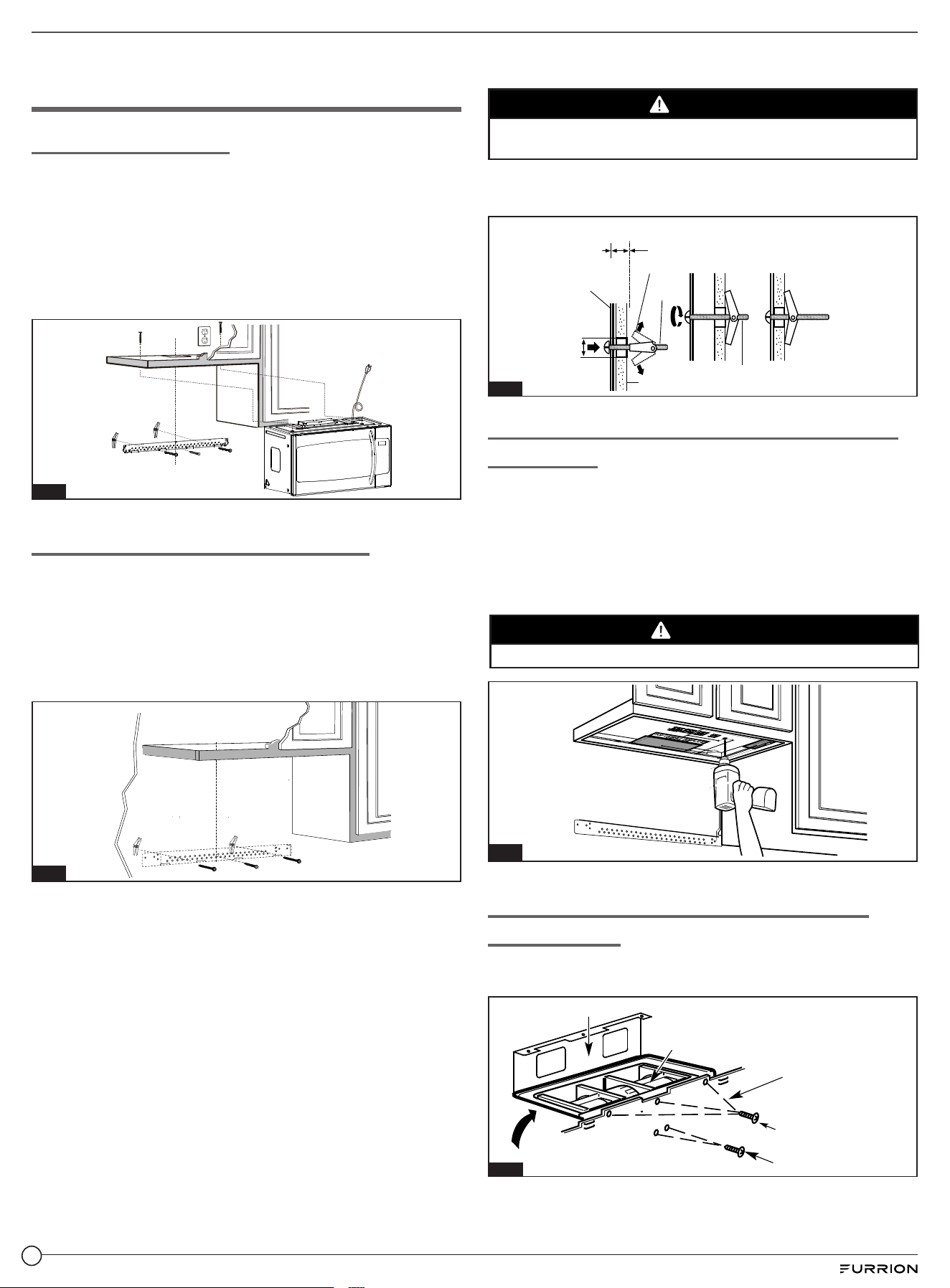
Attach The Mounting Plate to the Wall
Attach the mounting plate to the wall using the wing nuts and
machine screws (3/16” x 3”). At least one wood screw must be
used to attach the mounting plate to a wall stud.
1. Insert the machine screws (3/16” x 3”) into the mounting
plate through the holes designed to go into drywall and
attach the toggle wings to ¾” onto each machine screw
(3/16” x 3”). (Fig. 11)
Fig. 11
2. Place the mounting plate against the wall and insert the
toggle wings into the holes in the wall to mount the plate.
CAUTION
Be careful to avoid pinching fingers between the back of the
mounting plate and the wall.
3. Tighten all bolts. Pull the plate away from the wall to help
tighten the bolts. (Fig. 12)
Mounting
Plate
Wall
Wing Nut
Machine
Screw
Spacing for Toggles more
than Wall Thickness
Bolt End
⅝"
Fig. 12
Use Top Cabinet Template for Preparation of
Top Cabinet
NOTE: Cabinet depth maximum in recirculation mode
is 13” (33 cm).
You need to drill holes for the top support screws and a hole
large enough for the power cord to fit through. (Fig 13)
1. Read the instructions on the TOP CABINET TEMPLATE.
2. Tape it underneath the top cabinet bottom.
3. Drill the mounting screw holes, the power plug clearance
hole, and the exhaust ducting cutout.
CAUTION
Wear safety goggles when drilling holes in the cabinet
bottom.
Fig. 13
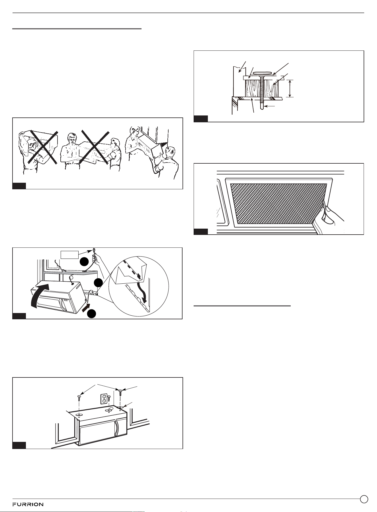
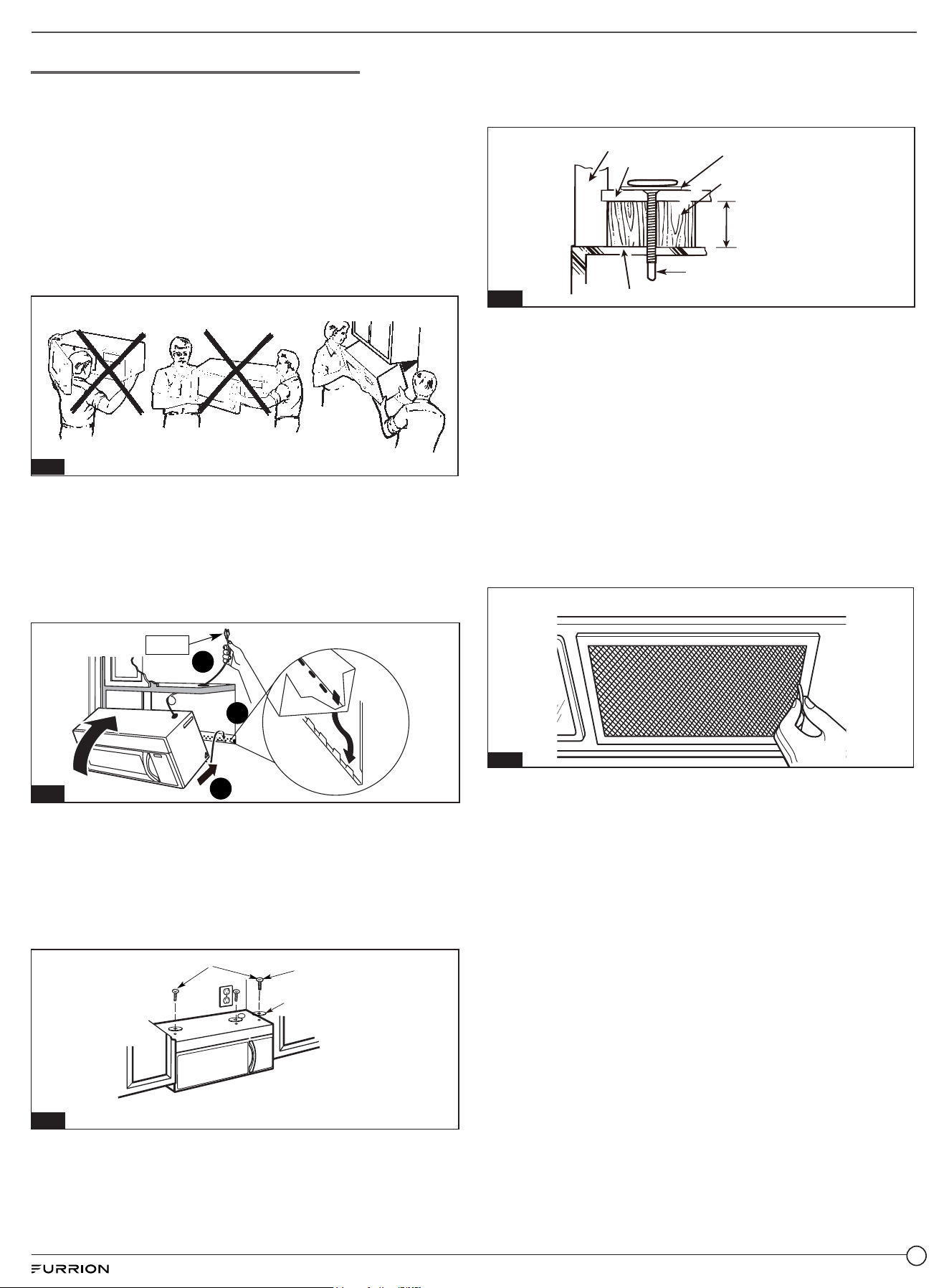
Mount the Microwave Oven (Fig. 14)
For easier installation and personal safety, we recommend
that two people install this microwave oven.
IMPORTANT:
Do not grip or use door handle during installation.
If filler blocks are not used, case damage may occur from
over tightening screws.
NOTE:
If your cabinet is metal, use the nylon grommet around the
power cord hole to prevent cutting of the cord.
We recommend using filler blocks if the cabinet front hangs
below the cabinet bottom shelf.
Fig. 14
1. Lift microwave, tilt it forward, and hook slots at back
bottom edge onto four lower tabs of mounting plate.
Rotate front of oven up against cabinet bottom. (Fig. 34)
NOTE: When mounting the microwave oven, thread the
power cord through the hole in bottom of top cabinet. Keep it
tight throughout Steps 1–3. Do not pinch cord or lift oven by
pulling cord. (Fig. 15)
3
1
NOTE
2
Fig. 15
2. Insert 2 self-aligning machine screws (¼”-20 x 3”) through
outer top cabinet holes. Temporarily secure the oven by
turning the screw at least two full turns after the threads
have engaged. (It will be completely tightened later.) Be
sure to keep power cord tight. Be careful not to pinch the
cord, especially when mounting flush to the bottom of
cabinet. (Fig. 16)
Turn two full turns on each screw
Self-aligning
Machine screw
Washer
Fig. 16
3. The Filler Block is only used for recessed cabinet and
front overhang cabinet (see the type of the cabinet on
page 4 and page 5), you should place the Filler Block to
the cabinet bottom before installing the oven. (Fig. 17)
Cabinet Front
Self-Aligning machine Screw
Equivalent to
Depth of Cabinet
Recess
Microwave Oven top
Cabinet Bottom
Filler Block
Washer
Fig. 17
4. Tighten the outer two screws to the top of the microwave
oven. (During tightening screws, hold the microwave oven
in place against the wall and the top cabinet.)
5. Install the grease filters. See the User Manual packed with
the microwave. (Fig. 18)
Fig. 18
6. Filters should be cleaned at least once a month. Soak
the filter in a sink or dish pan filled with hot water and
detergent. DO NOT use ammonia or other alkali; they will
react with the filter material and darken it.
Agitate and scrub with a brush to remove embedded dirt.
Rinse thoroughly and shake dry.
Replace by fitting the filter back into the opening.
Change the Charcoal Filter
See the User Manual packed with the microwave.
8
B. Outside Top Exhaust
(Vertical Duct) (Fig. 19)
Installation Overview
NOTE: Cabinet depth maximum in exhaust mode is 15½” (39 cm).
1. Attach the mounting plate to the wall.
2. Use top cabinet template for preparation of top cabinet.
3. Adapting Blower for Outside Top Exhaust (Vertical Duct).
4. Check for proper damper operation.
5. Mount the microwave oven.
6. Adjust the exhaust adapter.
7. Connecting ductwork.
Fig. 19
Attach the Mounting Plate to the Wall
Attach the mounting plate to the wall using the wing nuts and
machine screws (3/16” x 3”). At least one wood screw must be
used to attach the mounting plate to a wall stud.
1. Insert the machine screws (3/16” x 3”) into the mounting
plate through the holes designed to go into drywall and
attach the toggle wings to ¾” onto each machine screw
(3/16” x 3”). (Fig. 20)
Fig. 20
2. Place the mounting plate against the wall and insert the
toggle wings into the holes in the wall to mount the plate.
CAUTION
Be careful to avoid pinching fingers between the back of the
mounting plate and the wall.
3. Tighten all bolts. Pull the plate away from the wall to help
tighten the bolts. (Fig. 21)
Mounting
Plate
Wall
Wing Nut
Machine
Screw
Spacing for Toggles more
than Wall Thickness
Bolt End
⅝"
Fig. 21
Use Top Cabinet Template for Preparation of
Top Cabinet
NOTE: Cabinet depth maximum in exhaust mode is 15½” (39 cm).
You need to drill holes for the top support screws and a hole
large enough for the power cord to fit through. (Fig 22)
1. Read the instructions on the TOP CABINET TEMPLATE.
2. Tape it underneath the top cabinet bottom.
3. Drill the mounting screw holes, the power plug clearance
hole, and the exhaust ducting cutout.
CAUTION
Wear safety goggles when drilling holes in the cabinet bottom.
Fig. 22
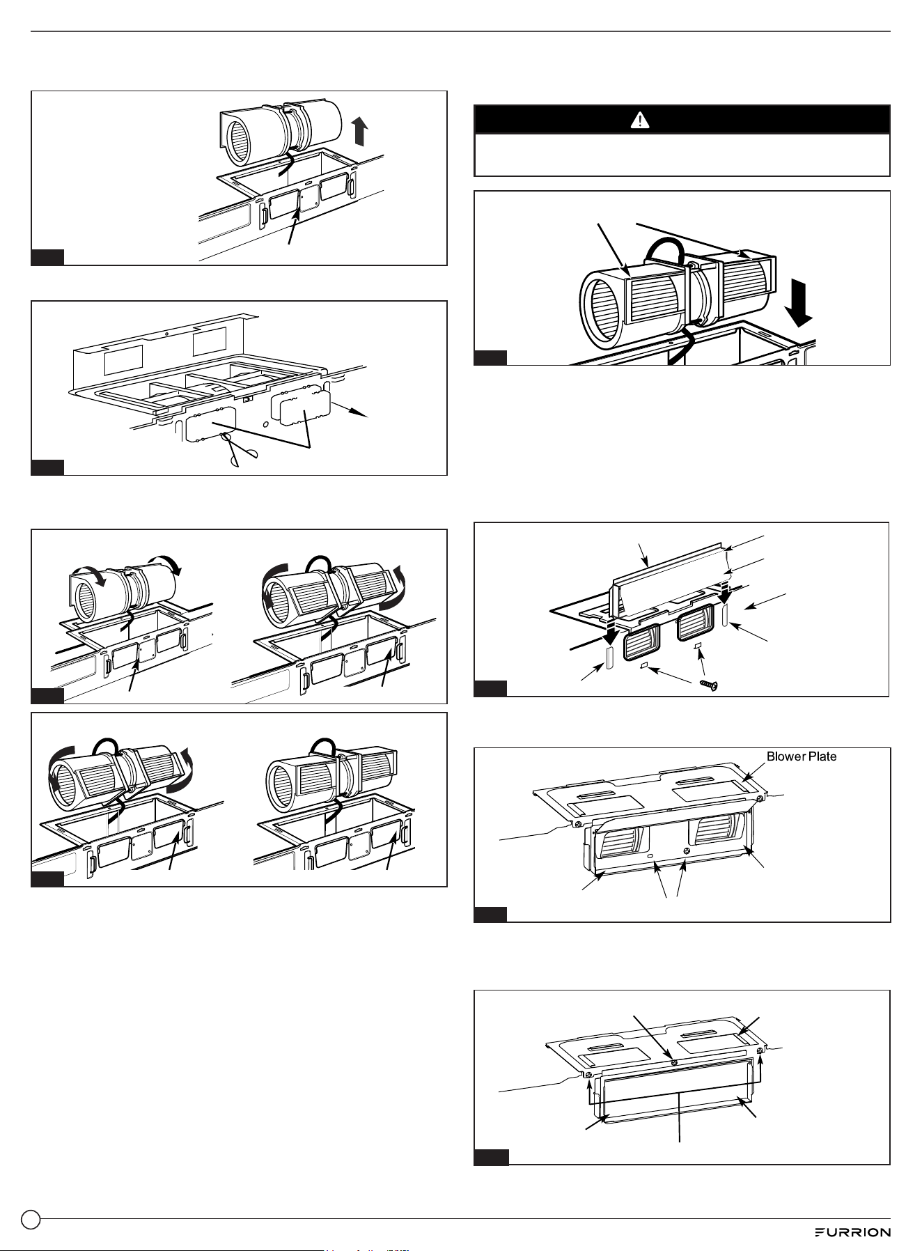
Adapting Blower for Outside Top Exhaust
(Vertical Duct)
1. Remove and save screws that holds blower motor to
microwave and lift up on the blower plate. (Fig. 23)
Bac
Blower Plate
k of
Microwave
Blower Motor
Screw
Blower Motor
Blower Plate screw
Blower Plate
Blower Motor
Screw
Back of
Microwave
Fig. 23
9
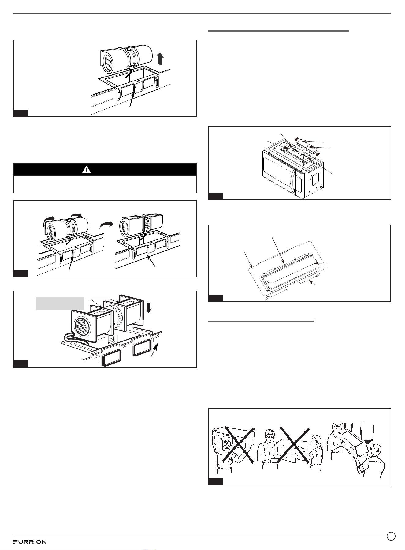
2. Carefully pull out the blower unit. The wires will extend far
enough to allow you to adjust the blower unit. (Fig. 24)
Default: Fan Blade
Openings Facing Forward
Back of Microwave
Fig. 24
3. Rotate the blower unit counterclockwise 90° into the
opening as shown in Fig 25 with the blower openings
facing upward.
NOTE: The blower unit exhaust openings should match
exhaust openings on upper of microwave oven.
CAUTION
Do not pull or stretch the blower unit wiring. Make sure the wires
are not pinched, and that they are properly secured.
Before Rotation
After
Back of Microwave
Back of Microwave
Before Rotation
After rolating 180°
Back of Microwave
Back of Microwave
After rolating counterclockwise 180°
Back of Microwave
Fig. 25
4. Replace the blower plate in the same position. (Fig 26)
AFTER: Fan Blade
Openings Facing Top
Back of
Microwave
Fig.26
Check for Proper Damper Operation
1. Place the microwave in its upright position, with the top of
the unit facing up.
2. The exhaust adapter is only used for top exhaust and
outside rear exhaust. It is not required on models installed
in recirculation exhaust mode.
3. Make sure the tape securing the damper flap is removed
and the damper flap pivots easily before mounting the
microwave.
4. Attach the exhaust adapter to the blower plate by sliding
it into the guides on top of the microwave. Secure the
adapter with one Sheet Metal Screw provided. (Fig. 27)
Blower Plate
Screw
Exhaust Adapter
Guide
Guide
Fig. 27
5. You need to fix your house exhaust onto the damper,
sealing it after the microwave is installed. (Fig. 28)
Exhaust Adaptor (not required on models
installed for recirculation exhaust)
Back of microwave
Damper
Blower Plate
Fig. 28
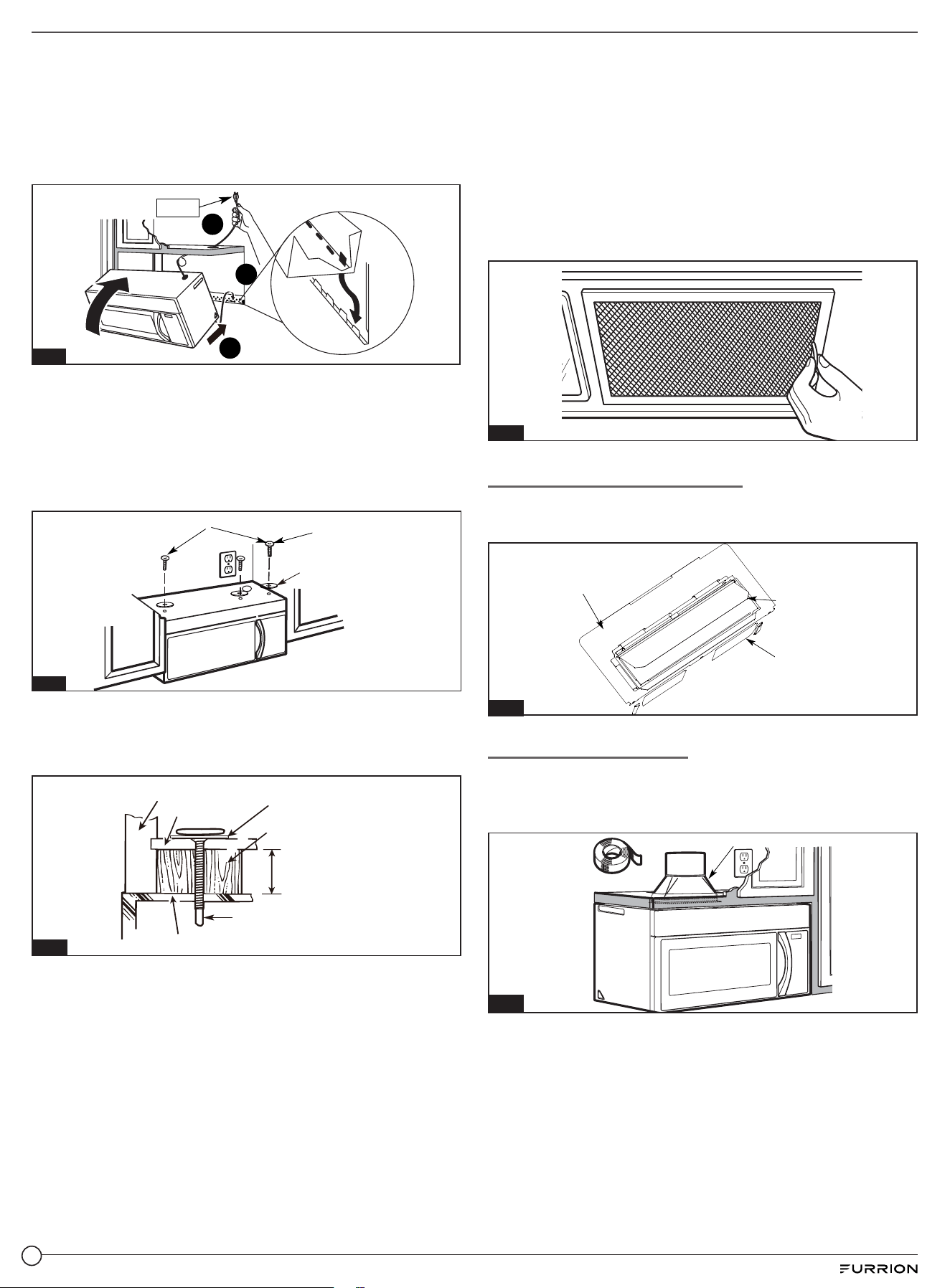
Mount the Microwave Oven
For easier installation and personal safety, we recommend
that two people install this microwave oven. (Fig. 29)
IMPORTANT: Do not grip or use door handle during
installation. If the filler blocks are not used, case damage may
occur from over tightening screws.
NOTE:
If your cabinet is metal, use the nylon grommet around the
power cord hole to prevent cutting of the cord.
We recommend using filler blocks if the cabinet front hangs
below the cabinet bottom shelf.
Fig. 29
10
1. Lift microwave, tilt it forward, and hook slots at back
bottom edge onto four lower tabs of mounting plate.
Rotate front of oven up against cabinet bottom. (Fig. 30)
NOTE: When mounting the microwave oven, thread the
power cord through the hole in bottom of top cabinet. Keep it
tight throughout Steps 1–3. Do not pinch cord or lift oven by
pulling cord. (Fig. 30)
3
1
NOTE
2
Fig. 30
2. Insert 2 self-aligning machine screws (¼”-20 x 3”) through
outer top cabinet holes. Temporarily secure the oven by
turning the screw at least two full turns after the threads
have engaged. (It will be completely tightened later.) Be
sure to keep power cord tight. Be careful not to pinch the
cord, especially when mounting flush to the bottom of
cabinet. (Fig. 31)
Turn two full turns on each screw
Self-aligning
Machine screw
Washer
Fig. 31
3. The Filler Block is only used for recessed cabinet and
front overhang cabinet (see the type of the cabinet on
page 4 & 5), you should place the Filler Block to the
cabinet bottom before installing the oven. (Fig. 32)
Cabinet Front
Self-Aligning machine Screw
Equivalent to
Depth of Cabinet
Recess
Microwave Oven top
Cabinet Bottom
Filler Block
Washer
Fig. 32
4. Tighten the outer two screws to the top of the microwave
oven. (During tightening screws, hold the microwave oven
in place against the wall and the top cabinet.)
5. Install the grease filters. (Fig. 33)
Filters should be cleaned at least once a month. Never
operate the vent fan or oven without the filters in place.
Pull down slightly on the tab toward the front of the oven
and remove the filter. Repeat for the other filter.
Soak the filter in a sink or dish pan filled with hot water and
detergent. DO NOT use ammonia or other alkali; they will
react with the filter material and darken it.
Agitate and scrub with a brush to remove embedded dirt.
Rinse thoroughly and shake dry.
Replace by fitting the filter back into the opening.
Fig. 33
Adjust The Exhaust Adapter
Open the top cabinet and adjust the exhaust adapter to
connect to the house duct. (Fig. 34)
Back of
Microwave
Damper
Blower Plate
Fig. 34
Connecting Ductwork
1. Extend the house duct down to connect to the exhaust
adapter.
2. Seal exhaust duct joints using duct tape. (Fig. 35)
House Duct
Fig. 35
11
C. Outside Back Exhaust
(Horizontal Duct) (Fig. 36)
Installation Overview
NOTE: Cabinet depth maximum in exhaust mode is 15½” (39 cm).
1. Preparing the rear wall template for outside back exhaust.
2. Attach the mounting plate to the wall.
3. Use top cabinet template for preparation of top cabinet.
4. Adapting microwave blower for outside back exhaust.
5. Mount the microwave oven.
Fig. 36
Preparing The Rear Wall Template For Outside
Back Exhaust (Fig. 37)
NOTE: Cabinet depth maximum in exhaust mode is 15½” (39 cm).
You need to cut an opening (4” x 12” square hole) in the rear
wall template for outside exhaust.
1. Read the instructions on the REAR WALL TEMPLATE.
2. Tape it to the rear wall, lining up with the holes previously
drilled for holes A and B in the wall plate.
3. Cut the opening, following the instructions of the REAR
WALL TEMPLATE.
Fig. 37
Attach The Mounting Plate To The Wall
Attach the mounting plate to the wall using the wing nuts and
machine screws (3/16” x 3”). At least one wood screw must be
used to attach the mounting plate to a wall stud.
1. Insert the machine screws (3/16”x 3”) into the mounting
plate through the holes designed to go into drywall and
attach the toggle wings to ¾” onto each machine screw
(3/16”x 3”). (Fig. 38)
Fig. 38
2. Place the mounting plate against the wall and insert the
toggle wings into the holes in the wall to mount the plate.
CAUTION
Be careful to avoid pinching fingers between the back of the
mounting plate and the wall.
3. Tighten all bolts. Pull the plate away from the wall to help
tighten the bolts. (Fig. 39)
Mounting
Plate
Wall
Wing Nut
Machine
Screw
Spacing for Toggles more
than Wall Thickness
Bolt End
⅝"
Fig. 39
Adapting Microwave Blower for Outside Back
Exhaust
1. Remove and save screws that holds blower motor to
microwave and lift up on the blower plate. (Fig. 40)
Bac
Blower Plate
k of
Microwave
Blower Motor
Screw
Blower Motor
Blower Plate screw
Blower Plate
Blower Motor
Screw
Back of
Microwave
Fig. 40
12
2. Carefully pull out the blower unit. The wires will extend far
enough to allow you to adjust the blower unit. (Fig. 41)
Default: Fan Blade
Openings Facing Forward
Back of Microwave
Fig. 41
3. Remove “Parts A” with Tin snips. (Fig. 42)
Part“A”
Fig. 42
4. Rotate blower unit counterclockwise 180°.
(Fig. 43 & Fig. 44)
Before Rotation
After
Back of Microwave
Back of Microwave
Before Rotation
After rolating 180°
Back of Microwave
Back of Microwave
After rolating counterclockwise 180°
Back of Microwave
Fig. 43
Before Rotation
After
Back of Microwave
Back of Microwave
Before Rotation
After rolating 180°
Back of Microwave
Back of Microwave
After rolating counterclockwise 180°
Back of Microwave
Fig. 44
5. Place the blower unit back into the opening. (Fig. 45)
NOTE: The blower unit exhaust openings should match
exhaust openings on rear of microwave oven.
CAUTION
Do not pull or stretch the blower unit wiring. Make sure the
wires are not pinched.
After Fan Blade
Openings Facing Back
Fig. 45
6. Replace the blower plate in the same position.
7. Attach the exhaust adapter to the rear of the oven by
sliding it into the guides at the top center of the back of
the oven. (Fig. 46)
NOTE: Push in securely until it is in the lower Blower
Motor screw. Take care to assure that the damper hinge is
installed so that it is at the top and that the damper swings
freely.
Guide
Back of
Microwave
Damper Hinge
Damper Flap
Blower Motor screw
Damper
Guide
Fig. 46
8. Secure the blower motor unit to the microwave with
screws as before. (Fig. 47)
Blower Motor screws
Back of
Microwave
Adaptor
Fig. 47
9. Secure the blower plate to the microwave with 3 screws
previously removed. Replace the blower plate in the same
position. (Fig. 48)
Blower plate screw
Blower Plate & Adaptor screw
Back of
Microwave
eBlow r Plate
aAd ptor
Fig. 48
13
Mount the Microwave Oven (Fig. 49)
For easier installation and personal safety, we recommend
that two people install this microwave oven.
IMPORTANT:
Do not grip or use door handle during installation.
If filler blocks are not used, case damage may occur from
over tightening screws.
NOTE:
If your cabinet is metal, use the nylon grommet around the
power cord hole to prevent cutting of the cord.
We recommend using filler blocks if the cabinet front hangs
below the cabinet bottom shelf.
Fig. 49
1. Lift microwave, tilt it forward, and hook slots at back
bottom edge onto four lower tabs of mounting plate.
Rotate front of oven up against cabinet bottom. (Fig. 52)
NOTE: When mounting the microwave oven, thread the
power cord through the hole in bottom of top cabinet. Keep it
tight throughout Steps 1–3. Do not pinch cord or lift oven by
pulling cord. (Fig. 50)
3
1
NOTE
2
Fig. 50
2. Insert 2 self-aligning machine screws (¼”-20 X 3”) through
outer top cabinet holes. Temporarily secure the oven by
turning the screw at least two full turns after the threads
have engaged. (It will be completely tightened later.) Be
sure to keep power cord tight. Be careful not to pinch the
cord, especially when mounting flush to the bottom of
cabinet. (Fig. 51)
Turn two full turns on each screw
Self-aligning
Machine screw
Washer
Fig. 51
3. The Filler Block is only used for recessed cabinet and
front overhang cabinet (see the type of the cabinet on
page 4 & 5), you should place the Filler Block to the
cabinet bottom before installing the oven. (Fig. 52)
Cabinet Front
Self-Aligning machine Screw
Equivalent to
Depth of Cabinet
Recess
Microwave Oven top
Cabinet Bottom
Filler Block
Washer
Fig. 52
4. Tighten the outer two screws to the top of the microwave
oven. (During tightening screws, hold the microwave oven
in place against the wall and the top cabinet.)
5. Install the grease filters. (Fig. 53)
Filters should be cleaned at least once a month. Never
operate the vent fan or oven without the filters in place.
Pull down slightly on the tab toward the front of the oven
and remove the filter. Repeat for the other filter.
Soak the filter in a sink or dish pan filled with hot water and
detergent. DO NOT use ammonia or other alkali; they will
react with the filter material and darken it.
Agitate and scrub with a brush to remove embedded dirt.
Rinse thoroughly and shake dry.
Replace by fitting the filter back into the opening.
Fig. 53
14

IG-FHA00028 V1.0
The con
tents of this manual are proprietary and copyright protected by Lippert. Lippert prohibits the copying or
dissemination of portions of this manual unless prior written consent for an authorized Lippert representation
has been provided. Any unauthorized use shall void any applicable warranty. The information contained in this
manual is subject to change without notice and at the sole discretion of Lippert. Revised editions are available
for free download from lippert.com.
Please recycle all obsolete materials.
For all concerns or questions, please contact Lippert
CCD-0006079
| REV DATE: 10.20.22