
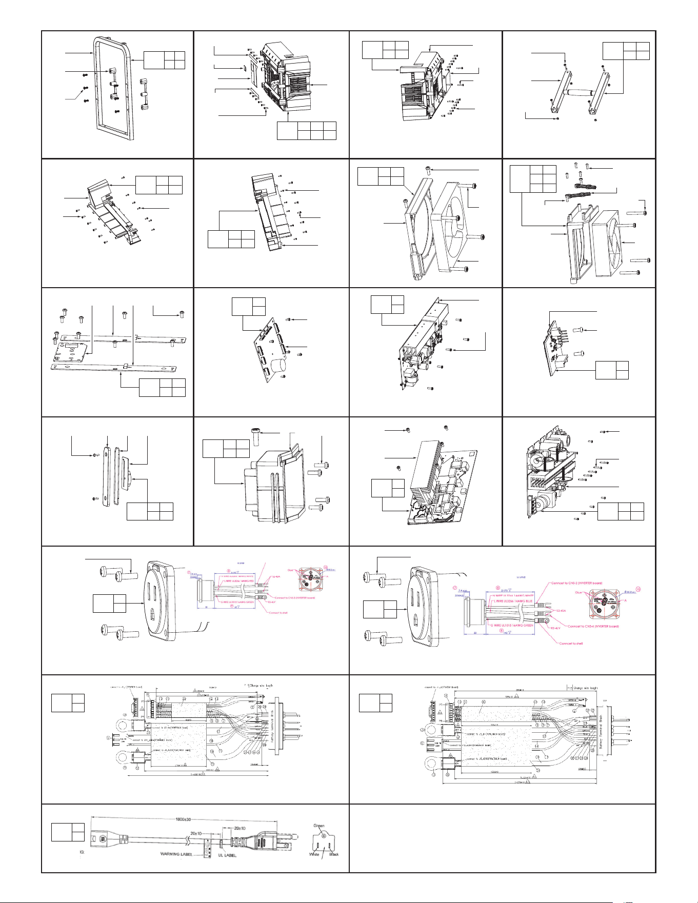
SERVICE PARTS LIST
BULLETIN NO.
Feb. 2022
STARTING
SERIAL NO.
EXAMPLE:
Component Parts (Small #) Are Included
When Ordering The Assembly (Large #).
See page two for assembly details.
00
0
WIRING INSTRUCTION
Pages 3 thru 6
DATEREVISED BULLETIN
54-00-F002
MX FUEL Portable Power Supply
SPECIFY CATALOG NO. AND SERIAL NO. WHEN ORDERING PARTS
MXF002
CATALOG NO.
FIG. PART NO. DESCRIPTION OF PART NO. REQ.
1 05-81-0171 M6 x 19mm Screw (12)
2 --------------- Roll Cage (2)
3 --------------- Roll Cage Joint (4)
4 44-04-0010 Foot Service Kit (Set of 4) (1)
5 05-81-0177 M3 x 12mm Screw (30)
6 05-81-0172 M4 x 12mm Screw (24)
7 --------------- Upper Charge Gauge Label (1)
8 --------------- Interface Label (1)
9 --------------- Outlet Socket (2)
10 --------------- MX FUEL Arming Label (1)
11 --------------- Lower Charge Gauge Label (1)
12 --------------- Front Housing (1)
13 --------------- One-Key Indicator Lens (1)
14 --------------- Warning Indicator Lens (1)
15 --------------- High Temp Indicator Lens (1)
16 05-81-0173 M1.7 x 6.5mm Screw (6)
17 --------------- Power Indicator Lens (1)
18 --------------- Power Button (1)
19 05-81-0174 M2.5 x 7mm Flat Washer Screw (5)
20 --------------- LED Lens-Fuel Gauge Upper (1)
21 --------------- LED Lens-Charge Gauge Upper (1)
22 05-81-0176 M3 x 7.5mm Screw (17)
23 --------------- HMI Main PCBA (1)
24 --------------- HMI PCBA (2)
25 --------------- Invertor PCBA (1)
27 --------------- Cable Fixing Bracket (2)
28 --------------- Left Fan Bracket (1)
29 14-20-0228 Strator PCBA (1)
30 05-81-0183 M3 x 12mm Screw (7)
31 --------------- Battery Slide-Left (1)
32 31-10-0022 Latch Plate (2)
33 --------------- Battery Release Lever (1)
34 --------------- Lever Biasing Spring (2)
35 --------------- Plunger Spring Mount (2)
36 --------------- Latch Lock Spring (4)
37 --------------- Latch Lock Plunger (2)
38 --------------- DC Switch (1)
39 --------------- AC Switch Bracket (2)
40 --------------- AC Switch (1)
41 --------------- Ejector Button (2)
42 --------------- Ejector Spring (4)
43 --------------- Ejection spring Mount (2)
44 43-62-0101 M5 Hex Nut (4)
45 --------------- 'H' Roll Cage (1)
46 05-81-0191 M4 x 16mm Screw (4)
47 --------------- Battery Slide-Right (1)
48 22-84-0016 Fan (1)
49 05-81-0179 M4 x 22mm Screw (8)
50 14-20-0224 Charger PCBA (1)
51 14-20-0231 BL PCBA (1)
52 --------------- Rear Housing (1)
53 14-20-0233 Coin Cell PCBA (1)
54 --------------- Coin Cell Battery Door Gasket (1)
55 --------------- Coin Cell Battery Door (1)
K23A
MILWAUKEE TOOL
l
www.milwaukeetool.com
13135 W. LISBON RD., BROOKFIELD, WI 53005
Drwg. 1
2
(2x)
3
(4x)
1
(12x)
4
(4x)
5
(8x)
9
(2x)
10
17
7
12
18
19
(5x)
14
15
8
16
(6x)
20
24
22
(17x)
23
29
65
21
64
67
36
(4x)
32
(2x)
71
(4x)
63
70
(2x)
41
(2x)
42
(4x)
47
72
(4x)
37
(2x)
43
(2x)
38
31
50
39
40
30
(?x)
28
47
48
52
53
54
55
46
(4x)
44
(4x)
45
58
(2x)
6
(?x)
60
(?x)
51
68
(4x)
56
57
27
(2x)
66
85
(6x)
35
(2x)
25
69
(2x)
70
(2x)
33
34
(2x)
33
49
(4x)
75
6
(12x)
79
(6x)
31
FIG. PART NO. DESCRIPTION OF PART NO. REQ.
56 --------------- AC Input Housing (1)
57 23-66-0163 AC Inlet (1)
58 05-81-0181 M2.6 x 4mm Screw (2)
59 43-76-0066 MX Fuel Badge (Not Shown) (1)
60 05-81-0171 M6 Washer (12)
61 05-81-0188 M4 x 6mm Washer Screw (Not Shown) (5)
63 14-20-0236 Power Mux PCBA (1)
64 --------------- LED Lens-Charge Gauge Lower (1)
65 --------------- LED Lens-Fuel Gauge Lower (1)
66 --------------- Right Fan Bracket (1)
67 22-84-0016 Fan (1)
68 05-81-0184 M4 x 32mm Screw (4)
69 --------------- Tool Terminal Block (2)
70 23-66-0163 AC Switch Button (2)
71 --------------- PM Pivot Bushing (4)
72 05-81-0186 M5 x 16mm Screw (4)
73 --------------- Torsion Spring (2)
74 --------------- Pillar (4)
75 43-76-0064 MX Fuel Badge (1)
76 --------------- Wire Lock (Not Shown) (3)
77 23-74-0022 Ground Terminal (Not Shown) (1)
78 05-81-0187 Ground Screw (Not Shown) (1)
79 05-81-0172 M4 x 12mm Screw (6)
80 --------------- Flat Washer (5)
81 --------------- M3 x 34mm Screw (5)
82 --------------- Rubber Pad (Not Shown) (2)
83 --------------- Rubber Pad (Not Shown) (1)
84 --------------- Rubber Pad (Not Shown) (1)
85 --------------- 2.5 x 7mm Screw (6)
100 42-46-0026 Roll Cage Service Kit (2)
101 23-33-0017 Top Outlet Socket Service Kit (2)
102 --------------- HMI PCBA Service Kit (1)
103 43-76-0064 Front Housing Service Kit (1)
104 22-84-0018 Left Fan Bracket Service Kit (1)
105 --------------- Strator PCBA Service Kit (1)
106 44-81-0013 Battery Slide-Left Service Kit (1)
107 43-62-0101 'H' Roll Cage Service Kit (1)
108 44-81-0017 Battery Slide-Right Service Kit (1)
109 --------------- Charger PCBA Service Kit (1)
110 --------------- BL PCBA Service Kit (1)
111 43-76-0066 Rear Housing Service Kit (1)
112 14-20-0233 Coin Cell PCBA Service Kit (1)
113 23-33-0012 AC Input Housing Service Kit (1)
114 --------------- Power Mux PCBA Service Kit (1)
115 22-84-0016 Right Fan Bracket Service Kit (1)
116 --------------- Invertor PCBA Service Kit (1)
117 23-33-0013 Bottom Outlet Socket Service Kit (1)
118 22-56-0027
Top Terminal Block, DC Switch & Wiring Harness
(1)
119 22-56-0029
Bottom Terminal Block, DC Switch & Wiring Harness
(1)
120 22-64-0045 Cord Service Kit (1)
SEE PAGE TWO FOR SERVICE KIT
LISTING AND DETAILS
2
3
(2x)
1
(6x)
100
1 2
3
42-46-0026
Roll Cage Service Kit
46
(4x)
45
44
(4x)
107
44 45
46
43-62-0101
‘H’ Roll Cage Service Kit
7
10
8
11
6
(12x)
12
103
6 7 8
10 11 12
43-76-0064
Front Housing Service Kit
43-76-0066
Rear Housing Service Kit
52
label
49
(4x)
6
(14x)
111
6 49
52
44-81-0013
Battery Slide-Left Service Kit
30
(7x)
31
6
(6x)
106
6 30
31
44-81-0017
Battery Slide-Right Service Kit
30
(6x)
6
(6x)
47
108
6 30
47
22-84-0018
Left Fan
Bracket
Service Kit
30
(2x)
49
(4x)
48
28
104
28 30
48 49
22-84-0016
Right Fan
Bracket
Service Kit
19(4x)
27(2x)
68(4x)
67
30
(2x)
66
115
19 27
30 66
67 68
24 23 25 22(10x)
102
22 23
24 25
HMI PCBA Service Kit
Strator PCBA Service Kit
22
(5x)
29
105
22
29
50
6
(6x)
109
6
50
Charger PCBA Service Kit
51
19
(2x)
110
19
51
BL PCBA Service Kit
58(2x) 55 54 53
112
53 54
55 58
14-20-0233
Coin Cell PCBA Service Kit
6 56 30(4x)
113
6 30
56
23-33-0012
AC Input Housing Service Kit
22
(5x)
63
114
22
63
Power Mux PCBA Service Kit
30
(7x)
61
(5x)
25
Invertor PCBA Service Kit
116
25 30
61
23-33-0017
Top Outlet Socket Service Kit
101
30
30(4x)
23-33-0013
Bottom Outlet Socket Service
30(4x)
117
30
118 119
22-56-0027
Top Terminal Block, DC Switch and Wiring Harness
22-56-0029
Bottom Terminal Block, DC Switch and Wiring Harness
120
22-64-0045
Power Cord
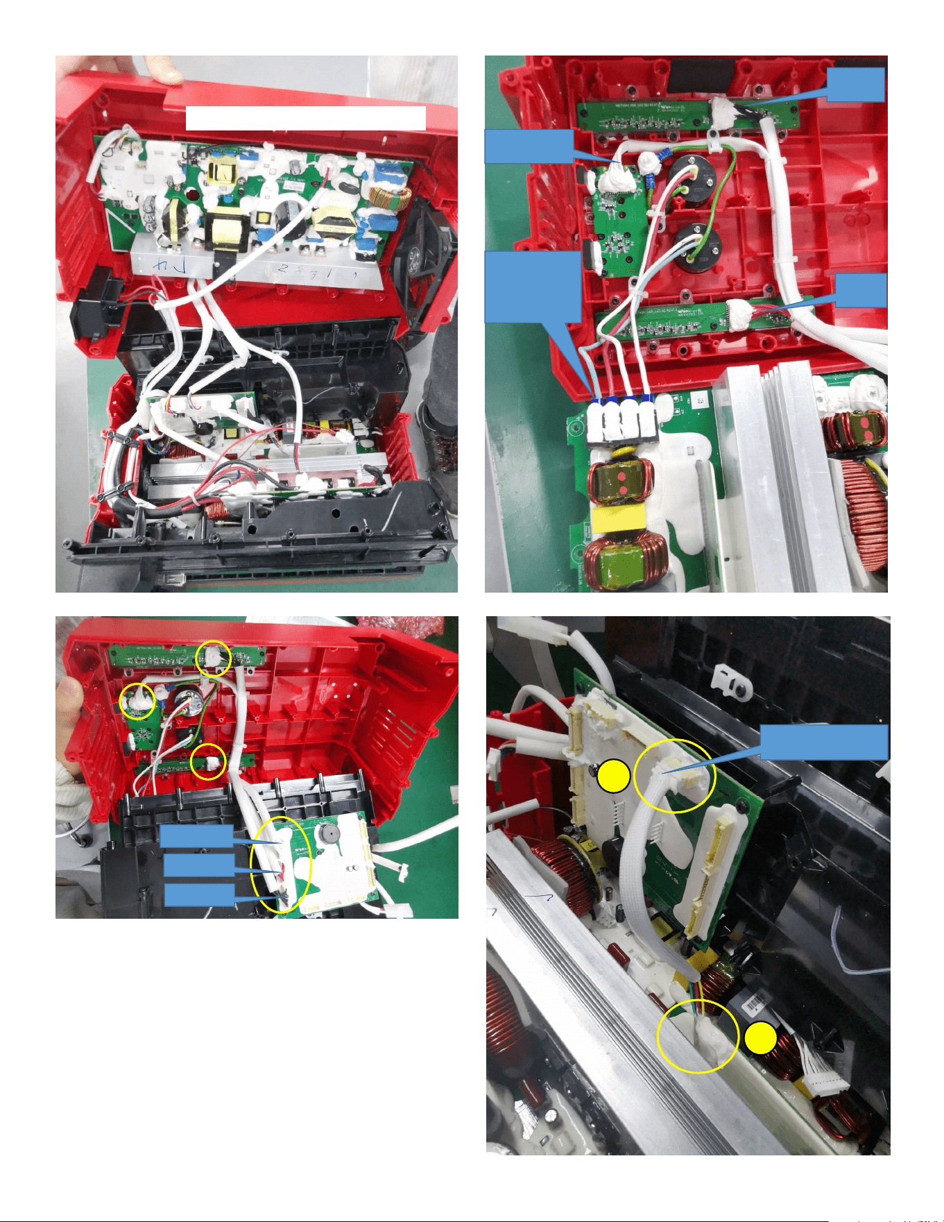
WIRE ROUTING OVERVIEW
White wire
Red wire
Black wire
Strator to inverter wire
105
116
105 116
Please pay
attention to the
order of wire
colors.
Black Wire
White Wire
Red Wire
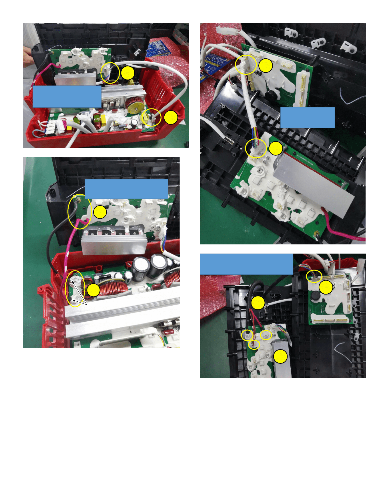
INVERTER TO POWERMUX-LVPS1
114
116
116 114
STRATOR TO POWERMUX
105
114
105 114
1. INVERTER TO POWERMUX_INVEB
2. INVERTER TO POWERMUX_INVER
The red wire is close to the
HEAT SINK
.
NOTE:
Black and red wires should be
switched at this location.
114
116
116 114
BATTERY B cable to Powermux and Strator
105
108
108 114
114
105
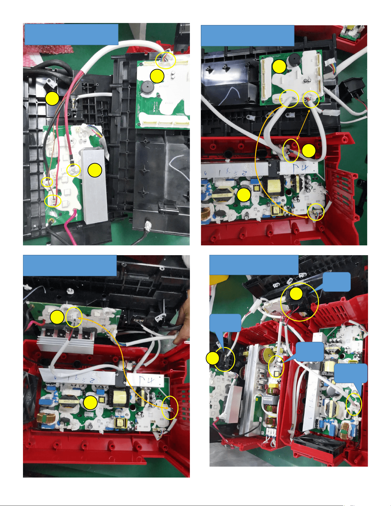
BATTERY A cable to Powermux and Strator
105
106
106 114
114
105
1. BLE TO STRATOR
2. CHARGE TO STRATOR
105
110
110
109
109
105
105
CHARGER TO POWERMUX-CHAR1
114
114109
109
ET51-411B-4 Inlet Module
AC input
AC input to
inverter
AC input to
charge board
AC switch
113
113
40
40
113
116
113
109
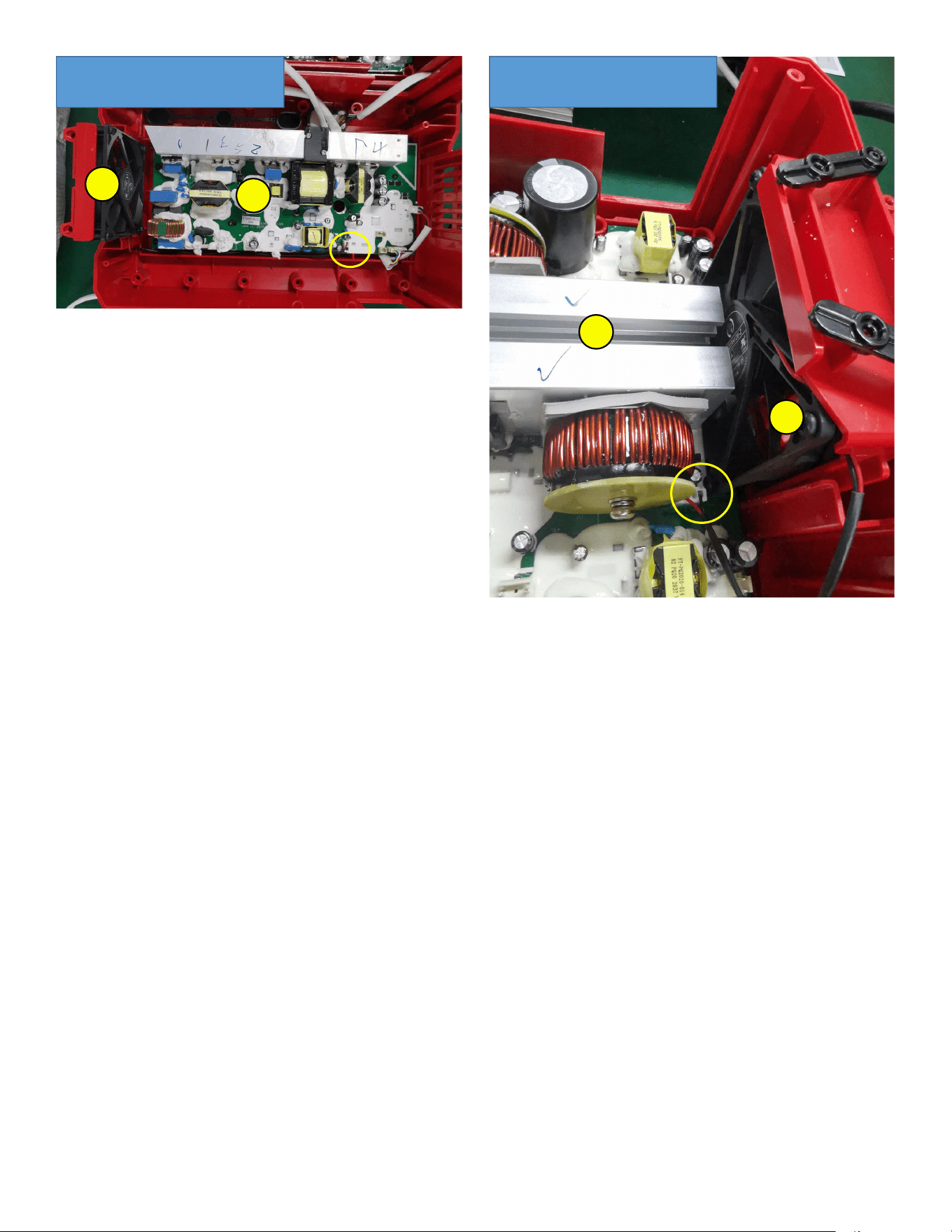
Charge FAN connector
115
109
109 115
inverter FAN connectior
115
116
116 115