Owner’s Manual
HPC-3000 / WPC-4000 / HPC-5000 / WPC-7000 / WPC-9000 / WPC-15000
Owner’s Manual
MODEL : HPC-3000 / WPC-4000 / HPC-5000 /
WPC-7000 / WPC-9000 / WPC-15000
Please read and save these instructions. Read carefully before attempting to assemble,
install, operate or maintain the product described.
Protect yourself and others by observing all safety information. Failure to comply with
instructions could result in personal injury andlor property damage! Retain instructions
for future reference.
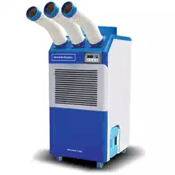
AmeriCool by Weltem Portable Air Condioners feature spot cooling for large
areas where cooling of the enre area is not praccal. A dedicated spot cooling
thermostat controls the unit in this applicaon. These air condioners can also
be used in smaller areas for room cooling.
A control panel provides ease of use and contains a self-diagnosc funcon and
display, showing operang modes, room and set temperatures, and faults. If an
abnormal operaon occurs, a visual display of the fault is shown. Caster wheels
are included for easy portability. Suitable applicaons include: a factory or work
place, industrial kitchen, computer room, emergency cooling, outdoor event, etc.
Aer unpacking the unit, carefully inspect unit for any damage that may
have occurred during transit. Check for any loose, missing, or damaged parts.
Descripon
Unpacking
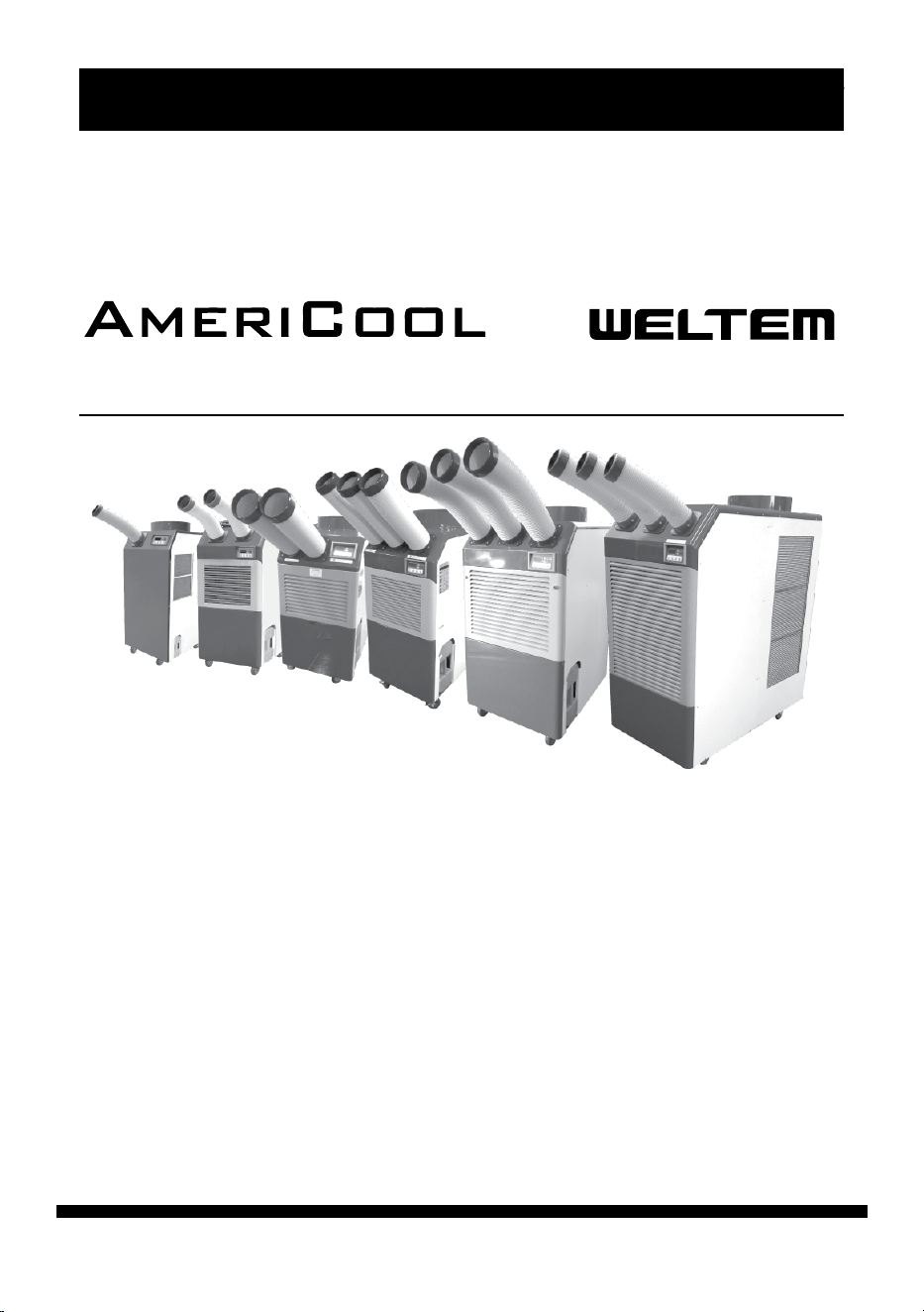
Portable Air Conditioners
by
HPC-3000
HPC-5000
WPC-4000
WPC-7000
WPC-9000
WPC-15000

page 2
Owner’s Manual
HPC-3000 / WPC-4000 /HPC-5000 / WPC-7000 / WPC-9000 / WPC-15000
Table of Contents
IMPORTANT SAFETY INSTRUCTIONS...........................................................4
INTRODUCTION..........................................................................................6
PRODUCT DESCRIPTION.............................................................................6
ASSEMBLY(HPC-3000).................................................................................7
Component Parts
Power Cord Holder
Discharge Ducts / Supply Air Duct
Exhaust Flange(Oponal)
Ambient Air Adapters(Oponal)
ASSEMBLY(HPC-4000).................................................................................8
Component Parts
Power Cord Holder
Discharge Ducts / Supply Air Duct
Exhaust Flange(Oponal)
Ambient Air Adapters(Oponal)
ASSEMBLY(HPC-5000).................................................................................9
Component Parts
Power Cord Holder
Rubber Stoppers
Discharge Ducts / Supply Air Duct
Exhaust Flange(Oponal)
Ambient Air Adapters(Oponal)
ASSEMBLY(WPC-7000,9000).....................................................................10
Component Parts
Power Cord Holder
Top Fan Exhaust Flange
Discharge Ducts / Supply Air Duct
Ambient Air Adapters(Oponal)
ASSEMBLY(WPC-15000)............................................................................11
Component Parts
Power Cord Holder
Discharge Ducts / Supply Air Duct
Exhaust Flange
Ambient Air Adapters(Oponal)

page 3
Owner’s Manual
HPC-3000 / WPC-4000 / HPC-5000 / WPC-7000 / WPC-9000 / WPC-15000
Thank you for selecng this AmeriCool by Weltem Portable Air Condion-
er. It provides you with spot cooling for large areas where cooling of an
enre area is not praccal or possible. Please read this manual before
installing the HPC-3000, WPC-4000, HPC-5000, WPC-7000, WPC-9000 or
WPC-15000 as it provides important informaon that should be followed
during installaon and maintenance of the Portable Air Condioner, al
-
lowing you to correctly set up your system for the maximum safety and
performance. Included is informaon on customer support and service,
if it is required. If you experience a problem with the unit, please refer to
the Troubleshoong secon in this manual to correct the problem. If the
problem is not corrected, please collect informaon so that the Technical
Support personnel can more eecvely assist you.
INSTALLATION GUIDE....................................................................................12
Moving the Unit
Plugging in the Unit
OPERATION..................................................................................................14
Control Panel
MAINTENANCE.............................................................................................15
Filter Cleaning
Spring Replacement
TROUBLESHOOTING.....................................................................................18
Alarm Codes
Troubleshoong Chart
SPECIFICATIONS............................................................................................21
WIRING DIAGRAM........................................................................................23
SHIPPING LIST...............................................................................................26
OBTAINING SERVICE.....................................................................................26
LIMITED WARRANTY.....................................................................................28
page 4
Owner’s Manual
HPC-3000 / WPC-4000 /HPC-5000 / WPC-7000 / WPC-9000 / WPC-15000
IMPORTANT SAFETY INSTRUCTIONS:
(SAVE THESE INSTRUCTIONS)
Please read this manual carefully for instrucons on correct installaon and
usage. Please read all safety instrucons.
1. Transport and store the unit in an upright posion only. Leave the unit in an
upright posion for at least 3 hours before use.
2. Always place the unit on an even, level surface.
3. Ensure the unit is connected to a grounded ulity of the correct rang / capacity.
4. The unit will cool when the room temperature is between 64.4°F - 113°F (18°C
- 45°C) depending on the thermostat seng.
5. DO NOT use this unit for funcons other than those described in this User’s
Manual.
6. DO NOT lt the unit.
7. DO NOT cover or obstruct the unit’s inlet and/or outlet grilles.
8. DO NOT use the unit in areas where it will be exposed to rain or water.
9. NEVER unplug the unit while it is operang
10. DO NOT place any foreign objects on the unit.
11. DO NOT operate the unit with wet or damp hands.
12. DO NOT allow chemical substances to come in contact with the unit.
13. DO NOT operate the unit in the presence of ammable substances or vapors
such as alcohols, pescides, gasoline, etc.
14. DO NOT use the plug to start or to stop the unit. Always use the control panel
to start and to stop the unit.
15. Always turn o the unit when it is not in use, and unplug the power plug from
the electrical outlet.
DO NOT use the unit in wet environments, such as a
laundry room, to avoid risk of electrical shock
DO NOT operate the unit in explosive or ammable
environments
WARNING
WARNING
page 5
Owner’s Manual
HPC-3000 / WPC-4000 / HPC-5000 / WPC-7000 / WPC-9000 / WPC-15000
16. Always turn the unit o and unplug the main power plug from the electrical
outlet before cleaning, moving, or performing maintenance.
17. AVOID the use of adapter plugs or extension cords. If it is necessary to use an
extension cord or an adapter plug to operate the unit, ensure that they are
correctly rated for the applicaon. Consult local qualied electrician and all
local electrical codes to ensure proper setup. Any extension cord used with
the device must be rated for a minimum of 15A.
18. DO NOT unplug the unit by pulling on the electrical cord. Keep the electrical
cord away from heat sources and always completely unroll the cord to avoid
overheang. If the power cord becomes damaged, a qualied service agent,
qualied electrician, or similarly qualied person must replace it, in order to
avoid a hazard or shock.
19. The lters must be used with the product at all mes. When the lters are
removed for cleaning, always ensure that the unit has been turned o and
unplugged from the electrical outlet.
20. Regularly clean the lters to maintain eciency. If the lters are not cleaned
regularly, the units output performance and eciency will decline and en
-
ergy consumpon will increase.
21. DO NOT operate the unit with a damaged power cord or plug, aer it mal
-
funcons, or if the unit has been dropped or damaged.
22. Only use the unit in the upright posion on a even, at surface. Unit must be
posioned at least 24 inches (60 cm) from the nearest object in any direc
-
on.
23. Stop operaon immediately if abnormal noise or odor is noced. Contact
local service center.
DO NOT operate a unit with a damaged power cord
WARNING

page 6
Owner’s Manual
HPC-3000 / WPC-4000 /HPC-5000 / WPC-7000 / WPC-9000 / WPC-15000
INTRODUCTION
PRODUCT DESCRIPTION
The informaon provided in this manual covers 13,200 – 60,000 BTU/
HR
AmeriCool by Weltem Portable Air Condioners, their basic funcons,
operang procedures, opons available and emergency situaons. It also
includes informaon on how to ship, store, handle, and install the equip
-
ment. Only detailed requirements of the Weltem Americool Portable Air
Condioners are described herein, and installaon must be carried out
in accordance with this manual. Electrical installaon must also carefully
follow local legislaon and regulaons. Only qualied personnel should
conduct these installaons as failure to acknowledge electrical hazards
could prove to be fatal.
AmeriCool by Weltem Portable Air Condioners feature spot cooling for
large areas where cooling of the enre area is not praccal or pos
-
sible. A dedicated spot cooling thermostat controls the unit in this
applicaon. These air condioners can also be used in smaller areas
for room cooling.
A control panel provides ease of use and contains self-diagnosc
funcons and displays, showing operang modes, room and set tem
-
peratures, and faults. If an abnormal operaon occurs, a visual display
of the fault is shown.
Caster wheels are included for ease of portability.
Suitable applicaons include: factory or work place, industrial kitchen,
computer room, emergency cooling, outdoor event, etc.
page 7
Owner’s Manual
HPC-3000 / WPC-4000 / HPC-5000 / WPC-7000 / WPC-9000 / WPC-15000
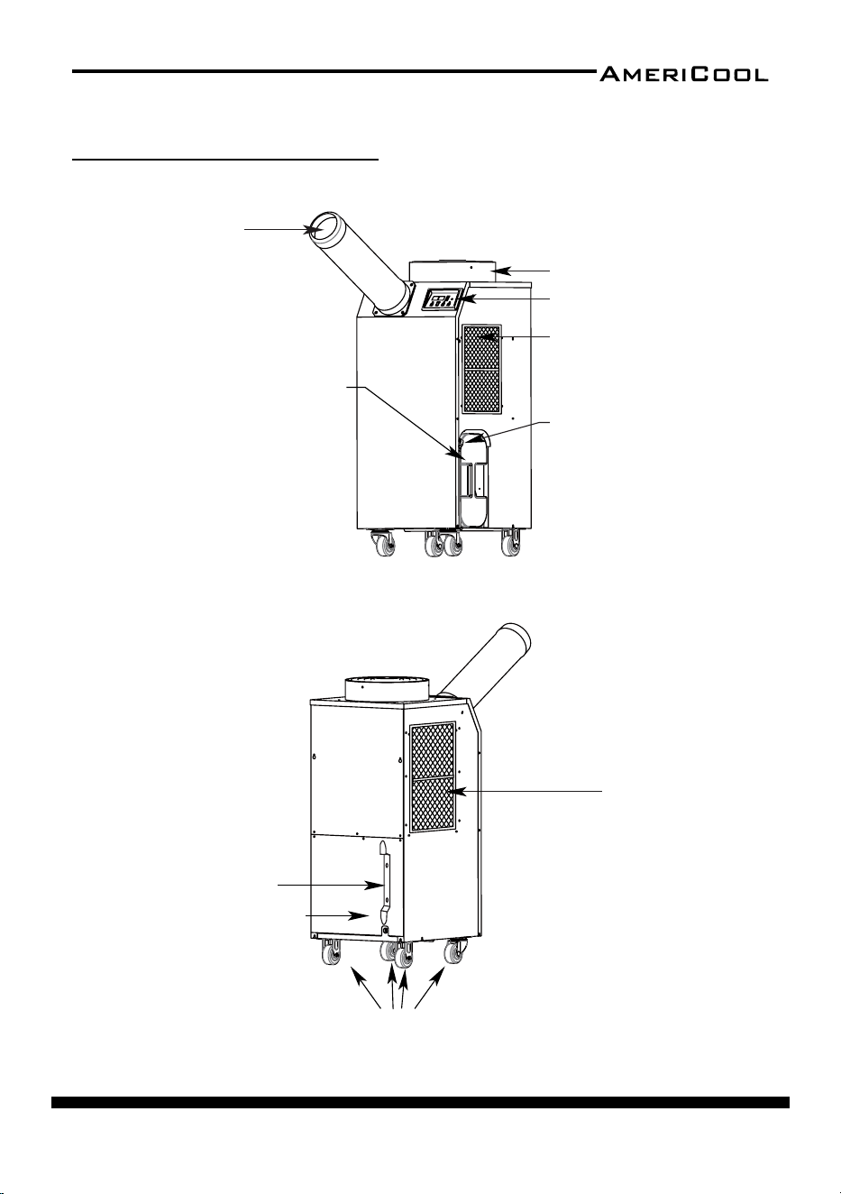
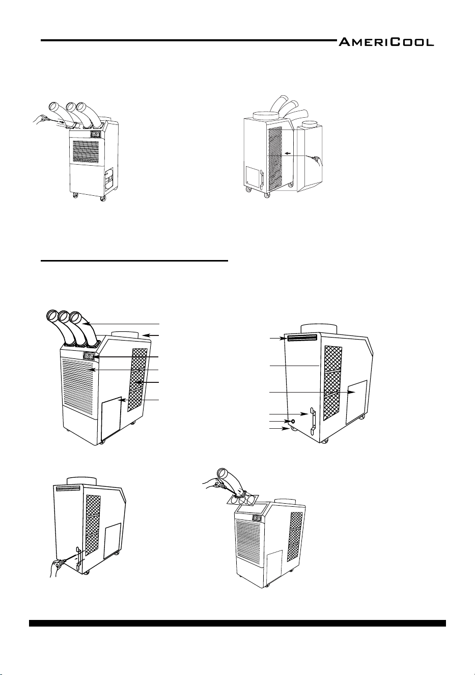
ASSEMBLY(HPC-3000)
Condenser / filter
Figure 2 – Rear and Le Side View
Cool air outlet hose
Display / Control board
Top fan wire grille
Evaporator / filter
Guide bar for
condensate
water tank
Condensate water tan
k
(Water level is sensed, and th
e
unit operaon is stopped when
tank is full. An alarm will be
displayed. Empty the tank an
d
replace to resume operaon)
Figure 1 – Front and Right Side View
Power cord holder
Electrical access panel
Casters
page 8
Owner’s Manual
HPC-3000 / WPC-4000 /HPC-5000 / WPC-7000 / WPC-9000 / WPC-15000
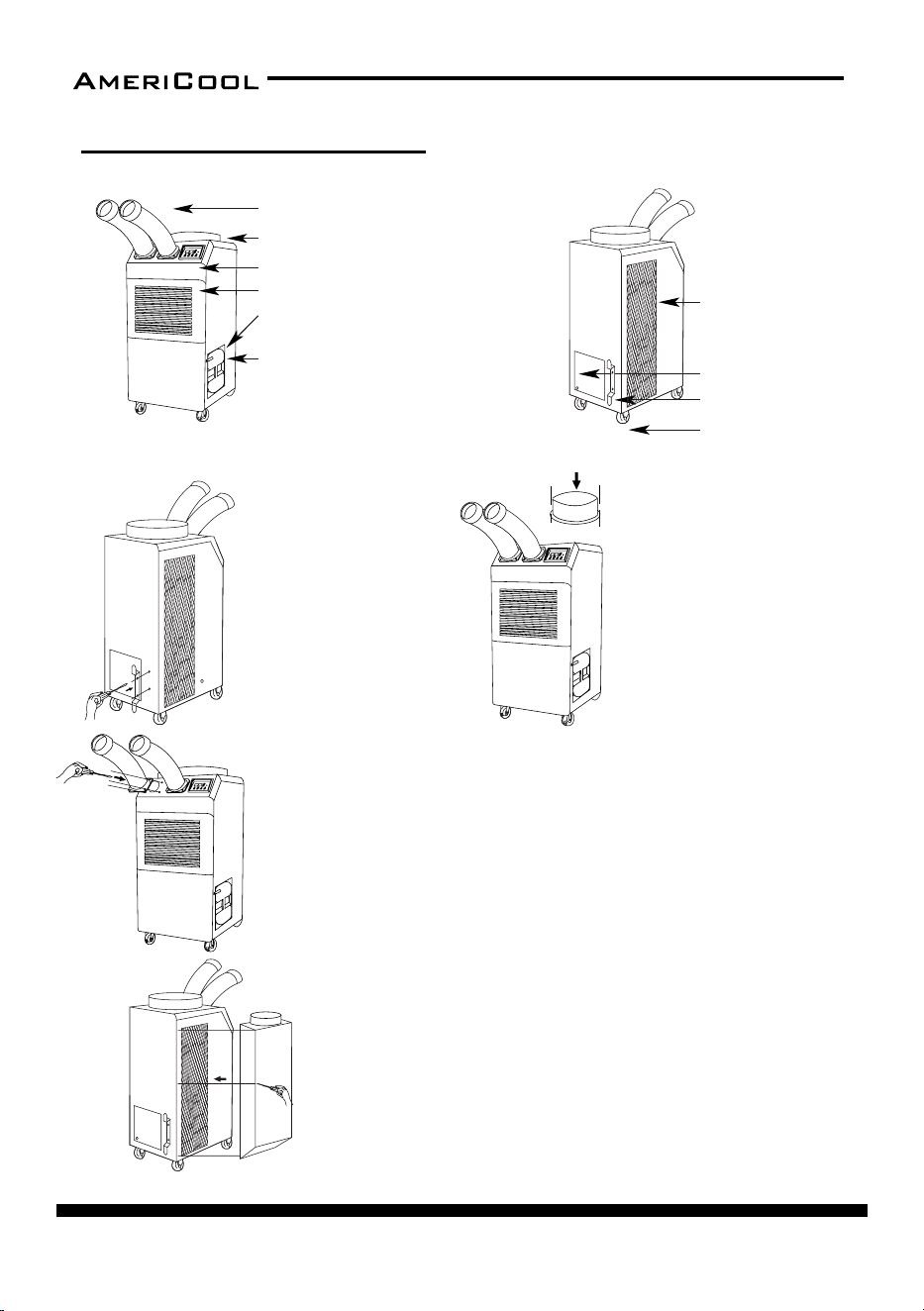
ASSEMBLY(WPC-4000)
COMPONENT PARTS
Cool air outlet hose
Display / Control board
Top fan exhaust flange
Evaporator / filter
Guide bar for condensate water tank
Condensate water tank (Water level is
sensed, and the unit operaon is stopped
when tank is full. An alarm will be
displayed. Empty the tank and replace to
resume operaon)
1. Take out the cord holder from
the accessory box.
2. Place the cord holder on the
back side of air condioner.
3. Use screws (enclosed inside
of accessory box with cord holder)
to install the cord holder on the
air condioner as shown in Figure 9.
1. Remove cool air outlet hose(s) from carton.
2. Place the cool air outlet hose(s) on the front top of air condioner.
3. Use screws (enclosed inside of box with cool air outlet hose(s) to install
the cool air outlet hose(s) on the air condioner as shown in Figure 11.
An ambient air adapter can be purchased separately. Air adapter
fits over the condenser to duct
condenser air to the unit to improve
cooling efficiency.
1. Remove air adapter from carton.
2. Place air adapter on the rear of air condioner.
3. Use screws (enclosed inside of box with air adapter) to install the
adapter on the air condioner as shown in Figure 12.
POWER CORD HOLDER
DISCHARGE DUCTS/SUPPLY AIR DUCT
Figure 8
Back and Le Side View
Figure 7
Front and Right Side View
Figure 9
Figure 11
Figure 12
Condenser / filter
Power cord holder
Caster
Electrical access panel
1. Remove the top fan exhaust
flange from carton.
2. Place the top fan exhaust flange
on the top of air condioner.
3. Use screws (enclosed inside
of box with the top fan exhaust
flange) to install the top fan
exhaust flange on air condioner
as shown in Figure 10.
TOP FAN EXHAUST FLANGE
Figure 10
AMBIENT AIR ADAPTER (Oponal)
page 9
Owner’s Manual
HPC-3000 / WPC-4000 / HPC-5000 / WPC-7000 / WPC-9000 / WPC-15000
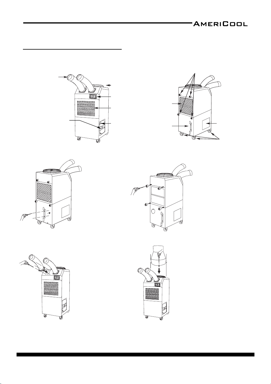
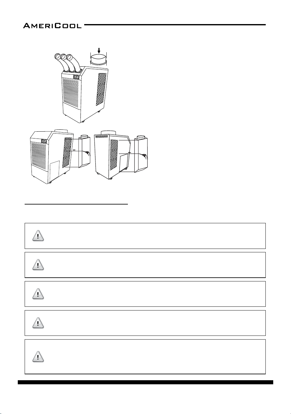
ASSEMBLY(HPC-5000)
Figure 18
Figure 19
Figure 14 – Rear and Le Side View
Rubber stoppers
Condenser / filter
Power cord holder
Casters
Electrical
access panel
Cool air outlet hose
Display / Control board
Top fan wire grille
Guide bar for
condensate
water tank
Figure 13 – Front and Right Side View
Evaporator / filter
Condensate water tank
(Water level is sensed, and
the unit operaon is
stopped when tank is full.
An alarm will be displayed.
Empty the tank and
replace to resume
operaon)
Figure 15 – Power Cord Holder aachment
1. Remove the power cord
holder from the accessory
pack.
2. Place the power cord
holder on the rear of the
unit as shown in Figure 15.
3. Use screws to install the
power cord holder to the
rear of the unit (screws
inside the accessory pack).
1. Remove the rubber stoppers
from the accessory pack.
2. Place the rubber stoppers on
the rear of the unit as shown in
Figure 16.
3. Use screws to install the
rubber stoppers to the rear of
the unit (screws inside the
accessory pack).
Figure 16 – Rubber Stopper aachment
An exhaust flange can be purchased
separately. Exhaust flange fits over the top
exhaust fan duct improving cooling
efficiency, allowing hot air to be exhausted
to another locaon.
1. Remove exhaust flange from carton.
2. Place exhaust flange on the top of air
condioner.
3. Use screws (enclosed inside of box with
exhaust flange) to install exhaust flange
on air condioner as shown in Figure 18.
AMBIENT AIR ADAPTER (Oponal)
An ambient air adapter can be purchased separately. Air adapter fits over the
condenser to duct condenser air to the unit to improve cooling efficiency.
1. Remove air adapter from carton.
2. Place air adapter on the rear of air condioner.
3. Use screws (enclosed inside of box with air adapter) to install the adapter
on the air condioner as shown in Figure 19.
Figure 17 – Cool Air Outlet aachment
1. Remove the cool air outlet
hose(s) from the box.
2. Place the cool air outlet hose(s)
on the front top of the unit as
shown in Figure 17.
3. Use screws to install the cool air
outlet hose(s) to the front of the
unit (screws aached to the cool
air outlet hose).
Component Parts
Power Cord Holder
Rubber Stoppers
Discharge Ducts /
Supply Air Duct
EXHAUST FLANGE
(Oponal)
page 10
Owner’s Manual
HPC-3000 / WPC-4000 /HPC-5000 / WPC-7000 / WPC-9000 / WPC-15000
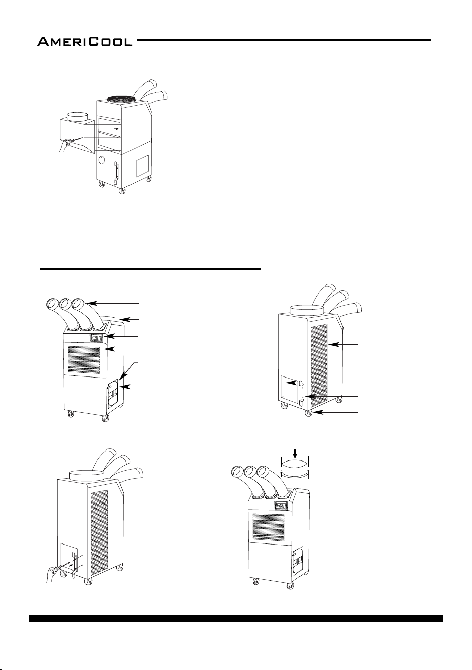
ASSEMBLY(WPC-7000,9000)
Cool air outlet hose
Front and Right Side View
Display / Control board
Top fan exhaust flange
Evaporator / filter
Guide bar for condensate water tank
Condensate water tank (Water level is
sensed, and the unit operaon is stopped
when tank is full. An alarm will be
displayed. Empty the tank and replace to
resume operaon)
Figure 21
Figure 20
Figure 22
Figure 24
Back and Le Side View
Condenser / filter
Power cord holder
Caster
Electrical access
panel
Figure 23
Figure 25
1. Remove cool air outlet hose(s) from
carton.
2. Place the cool air outlet hose(s) on
the front top of air condioner.
3. Use screws (enclosed inside of box
with cool air outlet hose(s) to install
the cool air outlet hose(s) on the air
condioner as shown in Figure 24.
An ambient air adapter can be
purchased separately. Air adapter fits
over the condenser to duct
condenser air to the unit to improve
cooling efficiency.
1. Remove air adapter from carton.
2. Place air adapter on the side of air
condioner.
3. Use screws (enclosed inside of box
with air adapter) to install the
adapter on the air condioner as
shown in Figure 25.
1. Take out the cord holder from
the accessory box.
2. Place the cord holder on the
back side of air condioner.
3. Use screws (enclosed inside of
accessory box with cord holder)
to install the cord holder on the
air condioner as shown in
Figure 22.
1. Remove the top fan exhaust
flange from carton.
2. Place the top fan exhaust flange
on the top of air condioner.
3. Use screws (enclosed inside of
box with the top fan exhaust
flange) to install the top fan
exhaust flange on air condioner
as shown in Figure 23.
Component Parts
POWER CORD HOLDER
TOP FAN EXHAUST FLANGE
DISCHARGE DUCTS
/SUPPLY AIR DUCT
AMBIENT AIR ADAPTER
(Oponal)
Figure 18
Figure 19
Figure 14 – Rear and Le Side View
Rubber stoppers
Condenser / filter
Power cord holder
Casters
Electrical
access panel
Cool air outlet hose
Display / Control board
Top fan wire grille
Guide bar for
condensate
water tank
Figure 13 – Front and Right Side View
Evaporator / filter
Condensate water tank
(Water level is sensed, and
the unit operaon is
stopped when tank is full.
An alarm will be displayed.
Empty the tank and
replace to resume
operaon)
Figure 15 – Power Cord Holder aachment
1. Remove the power cord
holder from the accessory
pack.
2. Place the power cord
holder on the rear of the
unit as shown in Figure 15.
3. Use screws to install the
power cord holder to the
rear of the unit (screws
inside the accessory pack).
1. Remove the rubber stoppers
from the accessory pack.
2. Place the rubber stoppers on
the rear of the unit as shown in
Figure 16.
3. Use screws to install the
rubber stoppers to the rear of
the unit (screws inside the
accessory pack).
Figure 16 – Rubber Stopper aachment
An exhaust flange can be purchased
separately. Exhaust flange fits over the top
exhaust fan duct improving cooling
efficiency, allowing hot air to be exhausted
to another locaon.
1. Remove exhaust flange from carton.
2. Place exhaust flange on the top of air
condioner.
3. Use screws (enclosed inside of box with
exhaust flange) to install exhaust flange
on air condioner as shown in Figure 18.
AMBIENT AIR ADAPTER (Oponal)
An ambient air adapter can be purchased separately. Air adapter fits over the
condenser to duct condenser air to the unit to improve cooling efficiency.
1. Remove air adapter from carton.
2. Place air adapter on the rear of air condioner.
3. Use screws (enclosed inside of box with air adapter) to install the adapter
on the air condioner as shown in Figure 19.
Figure 17 – Cool Air Outlet aachment
1. Remove the cool air outlet
hose(s) from the box.
2. Place the cool air outlet hose(s)
on the front top of the unit as
shown in Figure 17.
3. Use screws to install the cool air
outlet hose(s) to the front of the
unit (screws aached to the cool
air outlet hose).
Component Parts
Power Cord Holder
Rubber Stoppers
Discharge Ducts /
Supply Air Duct
EXHAUST FLANGE
(Oponal)
page 11
Owner’s Manual
HPC-3000 / WPC-4000 / HPC-5000 / WPC-7000 / WPC-9000 / WPC-15000
Cool air outlet hose
Front and Right Side View
Display / Control board
Top fan exhaust flange
Evaporator / filter
Guide bar for condensate water tank
Condensate water tank (Water level is
sensed, and the unit operaon is stopped
when tank is full. An alarm will be
displayed. Empty the tank and replace to
resume operaon)
Figure 21
Figure 20
Figure 22
Figure 24
Back and Le Side View
Condenser / filter
Power cord holder
Caster
Electrical access
panel
Figure 23
Figure 25
1. Remove cool air outlet hose(s) from
carton.
2. Place the cool air outlet hose(s) on
the front top of air condioner.
3. Use screws (enclosed inside of box
with cool air outlet hose(s) to install
the cool air outlet hose(s) on the air
condioner as shown in Figure 24.
An ambient air adapter can be
purchased separately. Air adapte
r fits
over the condenser to duct
condenser air to the unit to improve
cooling efficiency.
1. Remove air adapter from carton.
2. Place air adapter on the side of air
condioner.
3. Use screws (enclosed inside of bo
x
with air adapter) to install the
adapter on the air condioner as
shown in Figure 25.
1. Take out the cord holder from
the accessory box.
2. Place the cord holder on the
back side of air condioner.
3. Use screws (enclosed inside of
accessory box with cord holder)
to install the cord holder on the
air condioner as shown in
Figure 22.
1. Remove the top fan exhaust
flange from carton.
2. Place the top fan exhaust flange
on the top of air condioner.
3. Use screws (enclosed inside of
box with the top fan exhaust
flange) to install the top fan
exhaust flange on air condioner
as shown in Figure 23.
Component Parts
POWER CORD HOLDER
TOP FAN EXHAUST FLANGE
DISCHARGE DUCTS
/SUPPLY AIR DUCT
AMBIENT AIR ADAPTER
(Oponal)
Cool air outlet
Front and Right Side View
Display / Control board
Top fan exhaust flange
Evaporator / filter
Condenser / filter
Figure 27
Figure 26
Figure 28
Figure 29
Back and Le Side View
Condenser / filter
Power cord holder
Caster
Electrical access panel
Drain pump hose connector
Handle
Drain pump included
Figure 30
Figure 31
1. Remove cool air outlet hose(s) from
carton.
2. Place the cool air outlet hose(s) on
the front top of air condioner.
3. Use screws (enclosed inside of box
with cool air outlet hose(s) to install
the cool air outlet hose(s)
on the air condioner as shown in
Figure 29.
1. Take out the cord holder
from the accessory box.
2. Place the cord holder on
the back side of air condioner.
3. Use screws (enclosed inside of
accessory box ith cord
holder)to install the cord
holder on the air condioner
as shown in Figure 28.
EXHAUST FLANGE
1. Remove the top fan exhaust flange from carton.
2. Place the top fan exhaust flange on the top of air condioner.
3. Use screws (enclosed inside of box with the top fan exhaust flange)
to install the top fan exhaust flange on air condioner as shown in Figure 30.
AMBIENT AIR ADAPTERS
(Oponal)
Ambient air adapters can be purchased separately. Air
adapter fits over the condenser to duct condenser air to
the unit to improve cooling efficiency.
1. Remove air adapters from cartons.
2. Place air adapters on the both side of air condioner.
3. Use screws (enclosed inside of box with air adapter) to
install the adapter on the air condioner as shown in
Figure 31.
POWER CORD HOLDER
DISCHARGE DUCTS
/SUPPLY AIR DUCT
Component Part
s
ASSEMBLY(WPC-15000)
page 12
Owner’s Manual
HPC-3000 / WPC-4000 /HPC-5000 / WPC-7000 / WPC-9000 / WPC-15000
Cool air outlet
Front and Right Side View
Display / Control board
Top fan exhaust flange
Evaporator / filter
Condenser / filter
Figure 27
Figure 26
Figure 28
Figure 29
Back and Le Side View
Condenser / filter
Power cord holder
Caster
Electrical access panel
Drain pump hose connector
Handle
Drain pump included
Figure 30
Figure 31
1. Remove cool air outlet hose(s) from
carton.
2. Place the cool air outlet hose(s) on
the front top of air condioner.
3. Use screws (enclosed inside of box
with cool air outlet hose(s) to install
the cool air outlet hose(s)
on the air condioner as shown in
Figure 29.
1. Take out the cord holder
from the accessory box.
2. Place the cord holder on
the back side of air condioner.
3. Use screws (enclosed inside of
accessory box ith cord
holder)to install the cord
holder on the air condioner
as shown in Figure 28.
EXHAUST FLANGE
1. Remove the top fan exhaust flange from carton.
2. Place the top fan exhaust flange on the top of air condioner.
3. Use screws (enclosed inside of box with the top fan exhaust flange)
to install the top fan exhaust flange on air condioner as shown in Figure 30.
AMBIENT AIR ADAPTERS
(Oponal)
Ambient air adapters can be purchased separately. Air
adapter fits over the condenser to duct condenser air to
the unit to improve cooling efficiency.
1. Remove air adapters from cartons.
2. Place air adapters on the both side of air condioner.
3. Use screws (enclosed inside of box with air adapter) to
install the adapter on the air condioner as shown in
Figure 31.
POWER CORD HOLDER
DISCHARGE DUCTS
/SUPPLY AIR DUCT
Component Parts
WARNINGS REGARDING PROPER LOCATION FOR INSTALLATION
INSTALLATION GUIDE
DO NOT use the unit in explosive environments or
in areas where ammable gas leakage may occur
DO NOT use the unit in areas where it will be
exposed to rain or water
DO NOT use the unit in a corrosive atmosphere
DO NOT use the unit above 113˚ F (45˚ C)
DO NOT install the unit on uneven or sloping sur
-
face. The unit may roll or topple over even if casters
are set in the locked posion
WARNING
WARNING
WARNING
WARNING
WARNING
page 13
Owner’s Manual
HPC-3000 / WPC-4000 / HPC-5000 / WPC-7000 / WPC-9000 / WPC-15000
Moving the Unit
Unlock the casters and push the unit using the side handles to a at, level surface
and set the cater brakes to the locked posion.
Plugging in the Unit
Check the prongs and surface of the power cord plug for dust/dirt. If dust and/or
dirt are present, wipe o with a clean, dry cloth.
Check the power cord, plug, and prongs for damage or excess play.
If any damage or excess play is found, contact a qualied repair technician or a
qualied electrician to perform replacement of repair of the power cord, plug,
or prongs.
NOTE: Make sure the AC outlet is free of dirt, dust, oil, water, or any other for
-
eign material.
The unit is equipped with an approved NEMA plug conguraon (HPC-3000 =
5-15P; WPC-4000 = 5-20P; HPC-5000 = 6-15P; WPC-7000 = 6-20P; WPC-9000 =
6-30P ; WPC-15000 = 6-50P). The appropriate outlet must be used for each plug
type.
If the power cord or plug are damaged, repair
should only be performed by qualied electrician.
DO NOT connect / disconnect the power cord or
aempt to operate buons with wet hands. This
could result in electrical shock.
WARNING
WARNING
page 14
Owner’s Manual
HPC-3000 / WPC-4000 /HPC-5000 / WPC-7000 / WPC-9000 / WPC-15000
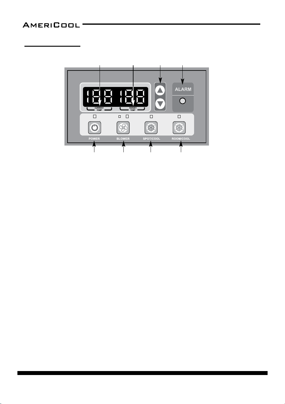
1. POWER BUTTON
• Acvates unit when POWER BUTTON is pressed.
• Fan starts on low speed.
• If POWER BUTTON is pressed during operaon, unit stops.
2. BLOWER BUTTON
• Changes fan speed from LOW to HIGH when pressed.
3. SPOT / COOL BUTTON
• Acvates compressor and begins producing cool air 5 seconds aer buon
is pressed.
• Regulates temperature based on outlet cool air temperature.
4. ROOM / COOL BUTTON
• Acvates compressor and produces cool air 5 seconds aer buon is
pressed.
• Regulates temperature based on inlet ambient air temperature.
5. SET TEMP BUTTON
• Change target temperature / data value by ± 1.
• Change data value by ± 10 by pressing connually.
• Press the SET TEMP BUTTONS to set temperature.
• Upper buon is to heighten temperature and lower buon is to lower tem
-
perature.
OPERATION
Control Panel
Figure 32 – Control Panel
1 2
5
3 4
6
87

page 15
Owner’s Manual
HPC-3000 / WPC-4000 / HPC-5000 / WPC-7000 / WPC-9000 / WPC-15000
6. ALARM
• Alarm indicator light blinks and indicates abnormal system operaon.
• If Alarm occurs, compressor stops.
• System operaon stops when ALARM light is acvated /blinking longer than
3 minutes.
7. CURRENT TEMP
• Room cool mode displays current room temperature in display in Fahren-
heit
• SPOT / COOL Mode displays outlet (cool air) temperature during normal
operaons.
• In order to change °F to °C, press SPOT / COOL and ROOM / COOL buons
together for 2 seconds.
• C will blink 2 mes and the gure will change to °C
• ALARM codes blink and are displayed when abnormal operaon occurs.
8. TARGET TEMP
• Displays the unit set temperature for ROOM COOL mode only
OFF-TIMER: Enter to Timer Seng Mode if you press BLOWER Buon and SPOT/
COOL Buon together for 1 seconds. Press UP/DOWN Buon to set the mer un
-
l it shows the gure you want to set. Aer 5 seconds, the gure will be memo-
rized and the compressor will stop aer the me set.
AUTO RESTART: If the unit goes o due to an electrical interrupon, the unit will
automacally restart when the power resumes.
MAINTENANCE
Filter Cleaning
1. To clean the evaporator lter, pull the front lter guard forward from the top
unl the guard is open (in an angled posion) and resng on the supporng
cables.
2. Slide the lter up and use a vacuum cleaner to remove the dust from the
lter.
page 16
Owner’s Manual
HPC-3000 / WPC-4000 /HPC-5000 / WPC-7000 / WPC-9000 / WPC-15000
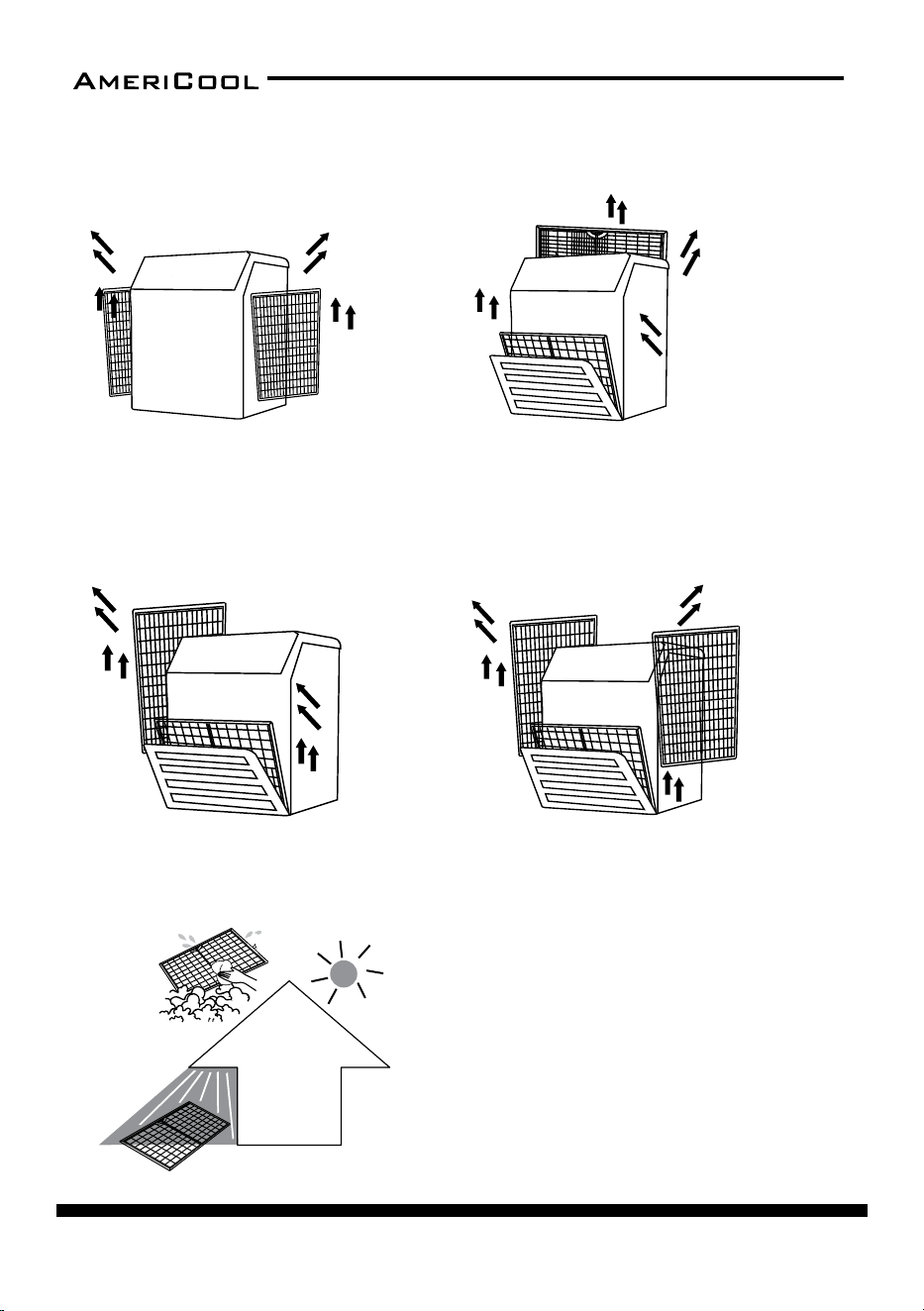
Figure 33 – Removing Filters
HPC-3000 HPC-5000
WPC-4000,7000,900
0W
PC-15000
– Remove dust from the filter
using a vacuum cleaner
hose aachment.
– If required wash the filter in
lukewarm water with a mild
detergent. Leave to dry in
a shaded area before
reinstalling.
Figure 34 – Removal of Dust
– Li up on the side filters from the middle bar
slightly and then angle the filter outwards from the
boom and remove.
– Pull the filter frame forward to remove the front filter.
– Slide filter up and use a vacuum cleaner to remove the
dust from the filter.
– Li up on the rear filter from the middle bar slightly and then
angle the filter outwards from the boom and remove.
– Loosen up 2 bolts on the front filter guard.
– Slide filter up and use a vacuum cleaner to remove the dust from the filter.
– Li up on the side filter from the middle bar slightly and then angle the filter outwards from the
boom and remove.
page 17
Owner’s Manual
HPC-3000 / WPC-4000 / HPC-5000 / WPC-7000 / WPC-9000 / WPC-15000
3. If the lter is heavily covered with dust and dirt, warm water and mild soap or
neutral detergent may be used to wash the lter. Do not use any other chemi
-
cals to clean the lter, as they will likely damage the lter.
4. Dry the lter in a shaded area before replacing it. Do not operate the unit
without the lter installed and the lter guard in the closed posion.
5. Replace the clean lter and close the lter guard.
6. To clean the condenser lter, li up on the rear or side lter from the middle
bar slightly and then angle the lter outwards from the boom and remove.
7. Use the same cleaning procedure as in steps 3-5 above.
8. To replace the condenser lter, place the top of the lter in the guide and slide
the lter up unl the boom of the lter clears the frame. Then push the bot
-
tom of the lter into the guide and let the lter gently fall inside the guide.
NOTE: For eecve cooling, clean the lter at least every 2 weeks.
DO NOT operate without the lter installed
DO NOT operate the unit with a damaged cord or
plug, aer the unit malfuncons, or if the unit has
been dropped or damaged.
WARNING
WARNING
page 18
Owner’s Manual
HPC-3000 / WPC-4000 /HPC-5000 / WPC-7000 / WPC-9000 / WPC-15000
The alarm light is acvated if abnormal operaon occurs, and a code is
displayed on the control panel. The compressor and condenser fan motor
will stop operang. The evaporator fan will connue to run for 3 minutes.
If the fault is reced within 3 minutes, the unit will resume operaon. If
the fault persists for more than 3 minutes, the evaporator fan also stops.
The fault must be reced before the unit can resume normal operaon.
TROUBLESHOOTING
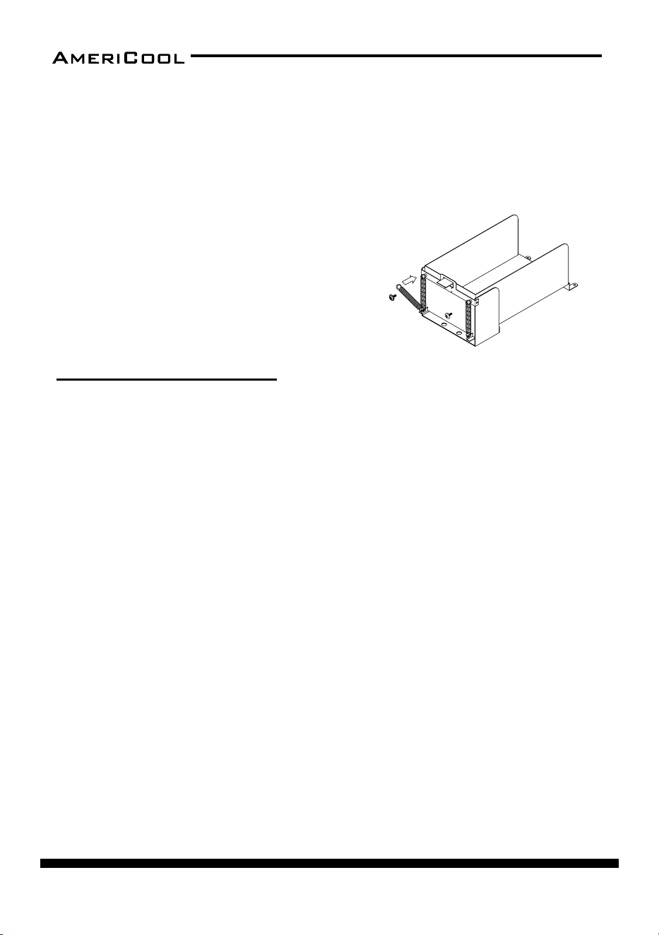
Spring Replacement
There are two springs on the rear of the condenser water tank guide.
1. Release the screw on the spring hook.
2. Take o the spring hook, and then pull out the opposite spring hook from
the hole in the condenser water tank guide.
3. Replace with a new spring in reverse order.
4. Repeat these steps for the other spring.
Figure 35 – Spring Replacement
page 19
Owner’s Manual
HPC-3000 / WPC-4000 / HPC-5000 / WPC-7000 / WPC-9000 / WPC-15000
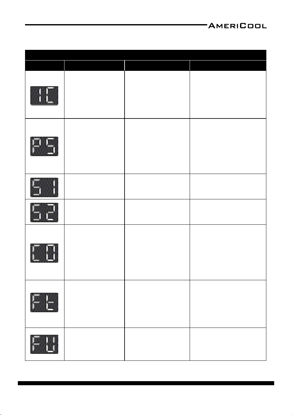
Alarm Codes
SELF-DIAGNOSTIC ALARM CODES
Alarm Display Problem Cause Correcve Acon
Frost prevenon
sensor and Abnormal
temperature sensor
value
• Indoor heat ex
-
changer temperature
too low
• TH3 temperature
sensor has a loose or
broken connecon
• Do not use the air
condioner if ambient
temperature is lower than
18°C (64°F)
• Contact a qualied service
agent
Refrigerant high
pressure switch
• Blocked air lter
• Blocked /kinked
exhaust duct
• Ambient temperature
is too high
• Clean air lter
• Ensure exhaust duct is not
blocked / kinked
• Do not use the air condi
-
oner if ambient tempera-
ture is higher than 45°C
(113°F)
Abnormal tempera
-
ture sensor value
TH1(Outlet) tempera
-
ture sensor has a loose
or broken connecon
Contact a qualied service
agent
Abnormal tempera
-
ture sensor value
TH2(Inlet) temperature
sensor has a loose or
broken connecon
Contact a qualied service
agent
Compressor over
-
loaded
• Ambient temperature
is too high
• Unstable voltage
supply
• Defecve compressor
• Do not use the air condi
-
oner if ambient tempera-
ture is higher than 45°C
(113°F)
• Contact a qualied service
agent
• Replace compressor
Condensate water
level alarm
Condensate tank is full
• Empty the water tank
• Aer installaon of the
water tank, press the
SPOT/COOL or ROOM/
COOL buon to resume
operaon
Drain pump alarm
Drain pump defecve
or improper hose con
-
necon (including kink
or blockage)
• Check the hose connec
-
on and hose
• Replace drain pump

page 20
Owner’s Manual
HPC-3000 / WPC-4000 /HPC-5000 / WPC-7000 / WPC-9000 / WPC-15000
Troubleshoong Chart
Symptom Possible Causes Correcve Acon
Water leakage
High water level in conden
-
sate tank
• Remove blockage from drain
hose
• Remove any object stuck un
-
derneath of the black panel
under the water tank
The unit doesn’t work
• Check the ulity to verify
that power is available to
the unit
• Verify that the power cord
is connected
• Reset the circuit breaker and
restart the unit
• Connect the power cord
No cold air ows from the
cold air outlet
• Ambient air cannot be
properly cooled if the lter
is dirty and not regularly
cleaned
• Compressor restart in 2
minutes aer turning o to
protect the compressor
• The ambient air tempera
-
ture may be too high
• Clean air lter
• Verify that 2 minutes have-
passed since the compressor
o
• The temperature of the com
-
pressor can be higher when
the ambient temperature is
too high. The compressor will
not work unless the ambient
air temperature is within the
acceptable operang range
of the unit
Water ow can be heard
aer compressor shuts o
No cause
Common to hear coolant ow
-
ing aer unit shuts o
Alarm displays “FT” with less
than half of the condensate
water in the tank
Spring is possibly broken
Replace the spring
(see Maintenance secon)
page 21
Owner’s Manual
HPC-3000 / WPC-4000 / HPC-5000 / WPC-7000 / WPC-9000 / WPC-15000
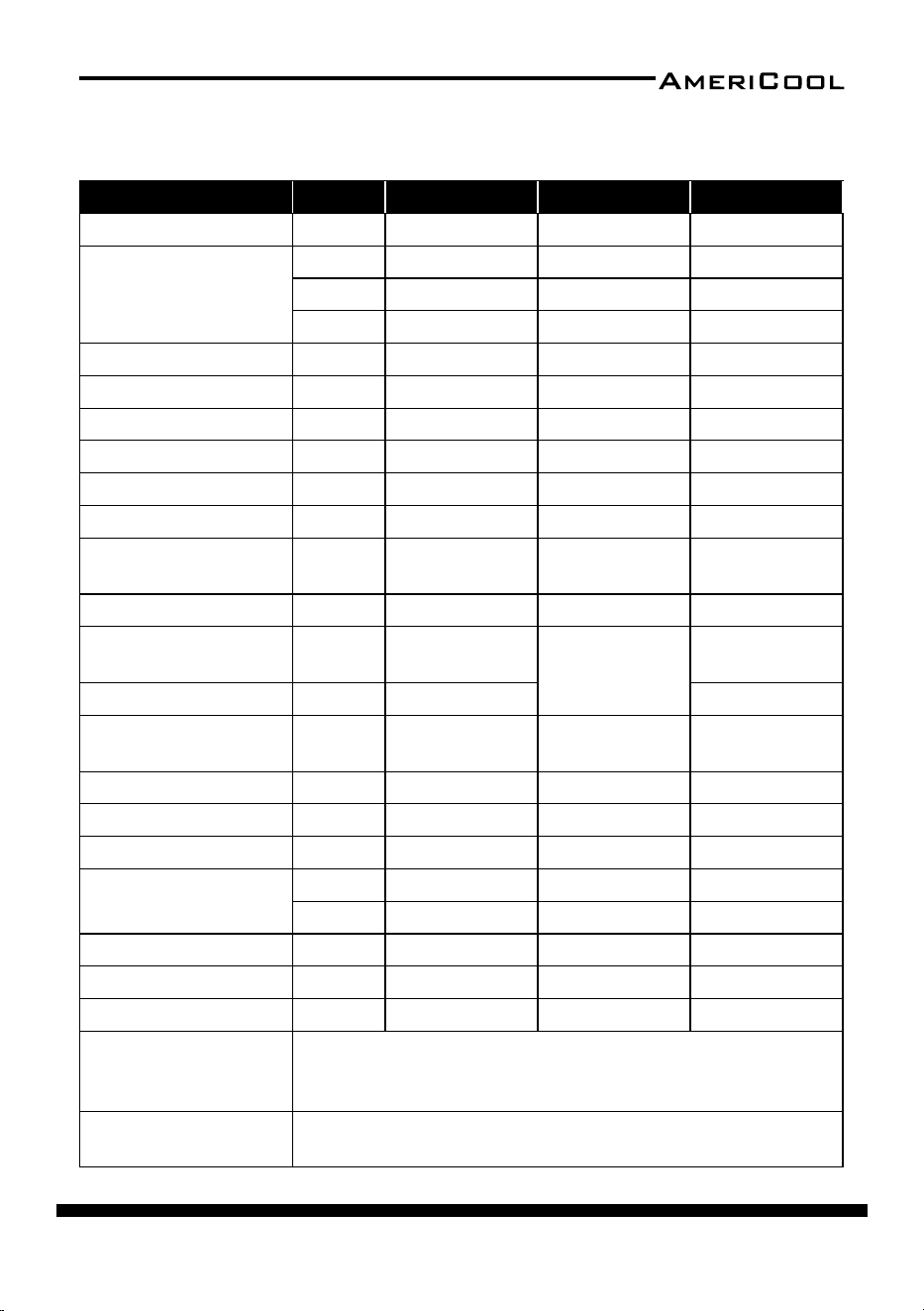
Specicaons
Specicaons Unit HPC-3000 WPC-4000 HPC-5000
Cooling Capacity BTU/HR 13,200 16,800 21,000
Power Supply
PHASE Single Single Single
VOLTS 115 115 208 / 230
HERTZ 60 60 60
Size (W x D x H) INCHES 17.5 x 19.9 x 43.3 20.5 x 26.1 x 40.9 22.0 x 24.4 x 50.4
Weight LBS 132 181 198
Current Consumpon AMPS 10.9 15.5 11.0 / 10.0
Circuit Breaker Size AMPS 15 20 15
Power Consumpon KW 1.3 1.7 2.3
Compressor Input KW 1.2 1.3 2.0
Air Flow (High/Low)
Evaporator
CFM 357 / 285 470 / 400 464 / 393
Air Flow Condenser CFM 610 1250 /1120 857
Motor Input (High/
Low) Evaporator
KW 0.091 / 0.089
0.36 / 0.26
0.24 / 0.20
Motor Input Condenser KW 0.08 0.26
Air Filter Aluminum
Aluminum /
Vinyl chloride
Aluminum /
Vinyl chloride
NEMA Plug TYPE 5-15P 5-20P 6-15P
Power Cord Gauge AWG 14 12 14
Power Cord Length FT 10 6 10
Refrigerant
TYPE R410A R410A R410A
OZ 15.5 35.2 42.3
Operang Condions °F 64-113 64-104 64-113
Hot Air Duct Diameter INCHES 12 12 16
Maximum Duct Length FT 30 50 30
Safety Devices
Compressor overload protector, An-freezing thermister, Full drain
tank switch, Automac restart (Power interrupon), Compressor
me delay program, High pressure switch
Features
Temperature control, Self-diagnosc funcon, Two speed fan, Op
-
onal drain pump kit, Washable lters,˚F(˚C)display
page 22
Owner’s Manual
HPC-3000 / WPC-4000 /HPC-5000 / WPC-7000 / WPC-9000 / WPC-15000
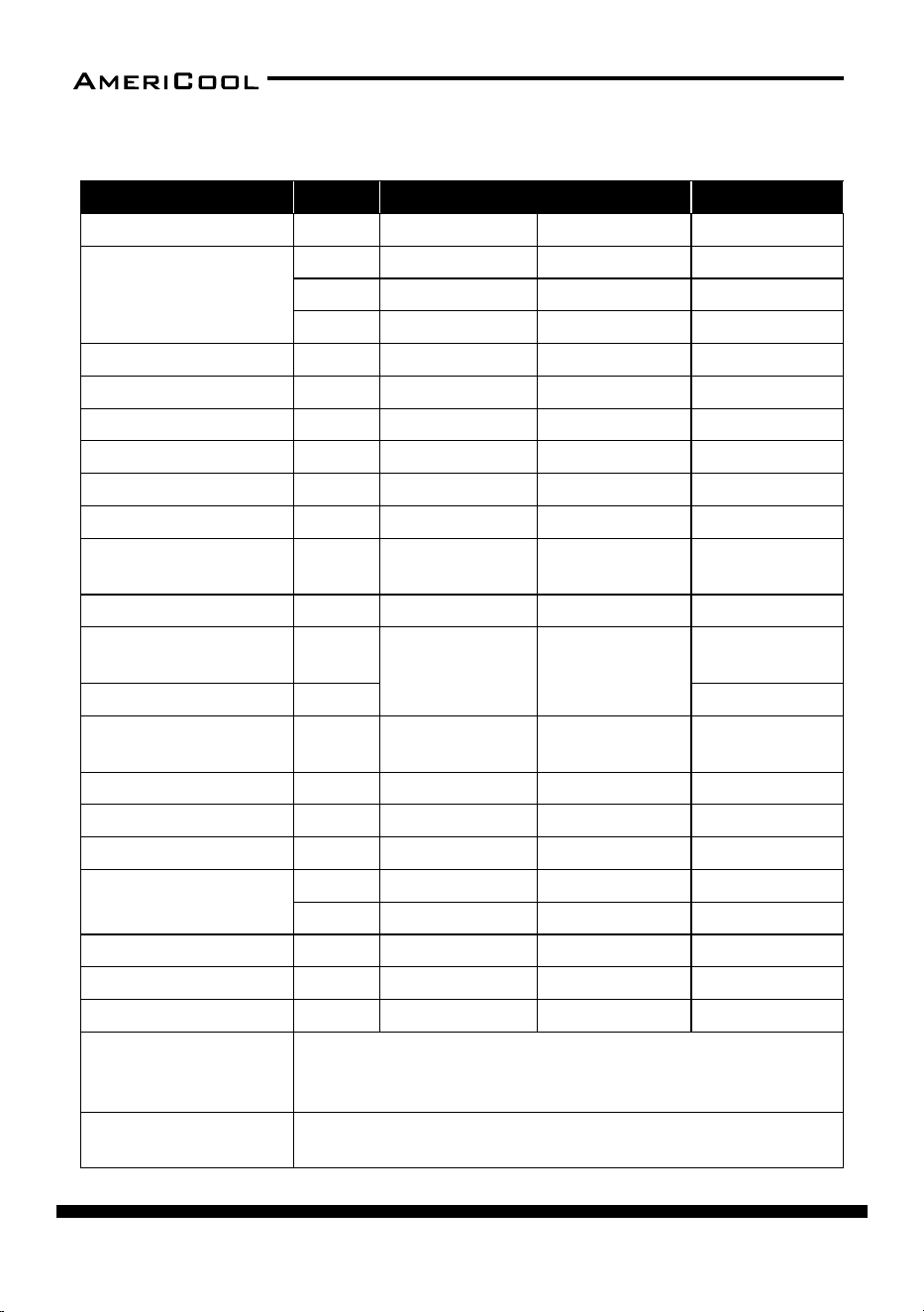
Specicaons Unit WPC-7000 WPC-9000 WPC-15000
Cooling Capacity BTU/HR 29,000 37,000 60,000
Power Supply
PHASE Single Single Single
VOLTS 208 / 230 208 / 230 208 / 230
HERTZ 60 60 60
Size (W x D x H) INCHES 22.0 x 29.4 x 47.3 26.0 x 33.3 x 52.4 28.9 x 51.5 x 59.8
Weight LBS 216 254 661
Current Consumpon AMPS 15.1 / 14.8 20.0 / 19.0 32.0/30.0
Circuit Breaker Size AMPS 20 30 50
Power Consumpon KW 3.3 4.4 7
Compressor Input KW 2.4 3.5 4.8
Air Flow (High/Low)
Evaporator
CFM 741 / 635 882 / 776 2000 / 1870
Air Flow Condenser CFM 1560 1660 3600
Motor Input (High/
Low) Evaporator
KW
0.9/0.8 0.6/0.5
0.4/0.35
Motor Input Condenser KW 1
Air Filter
Aluminium /
Vinyl chloride
Aluminium /
Vinyl chloride
Aluminium /
Vinyl chloride
NEMA Plug TYPE 6-20P 6-30P 6-50P
Power Cord Gauge AWG 12AWG 10AWG 8AWG
Power Cord Length FT 10 10 6
Refrigerant
TYPE R-410a R-410a R-410a
OZ 44.4 61 91
Operang Condions °F 64~113 64~113 64~113
Hot Air Duct Diameter INCHES 16 16 20
Maximum Duct Length FT 60 60 100
Safety Devices
Compressor overload protector, An-freezing thermister, Full drain
tank switch, Automac restart (Power interrupon), Compressor
me delay program, High pressure switch
Features
Temperature control, Self-diagnosc funcon, Two speed fan, Op
-
onal drain pump kit, Washable lters,˚F(˚C)display
page 23
Owner’s Manual
HPC-3000 / WPC-4000 / HPC-5000 / WPC-7000 / WPC-9000 / WPC-15000
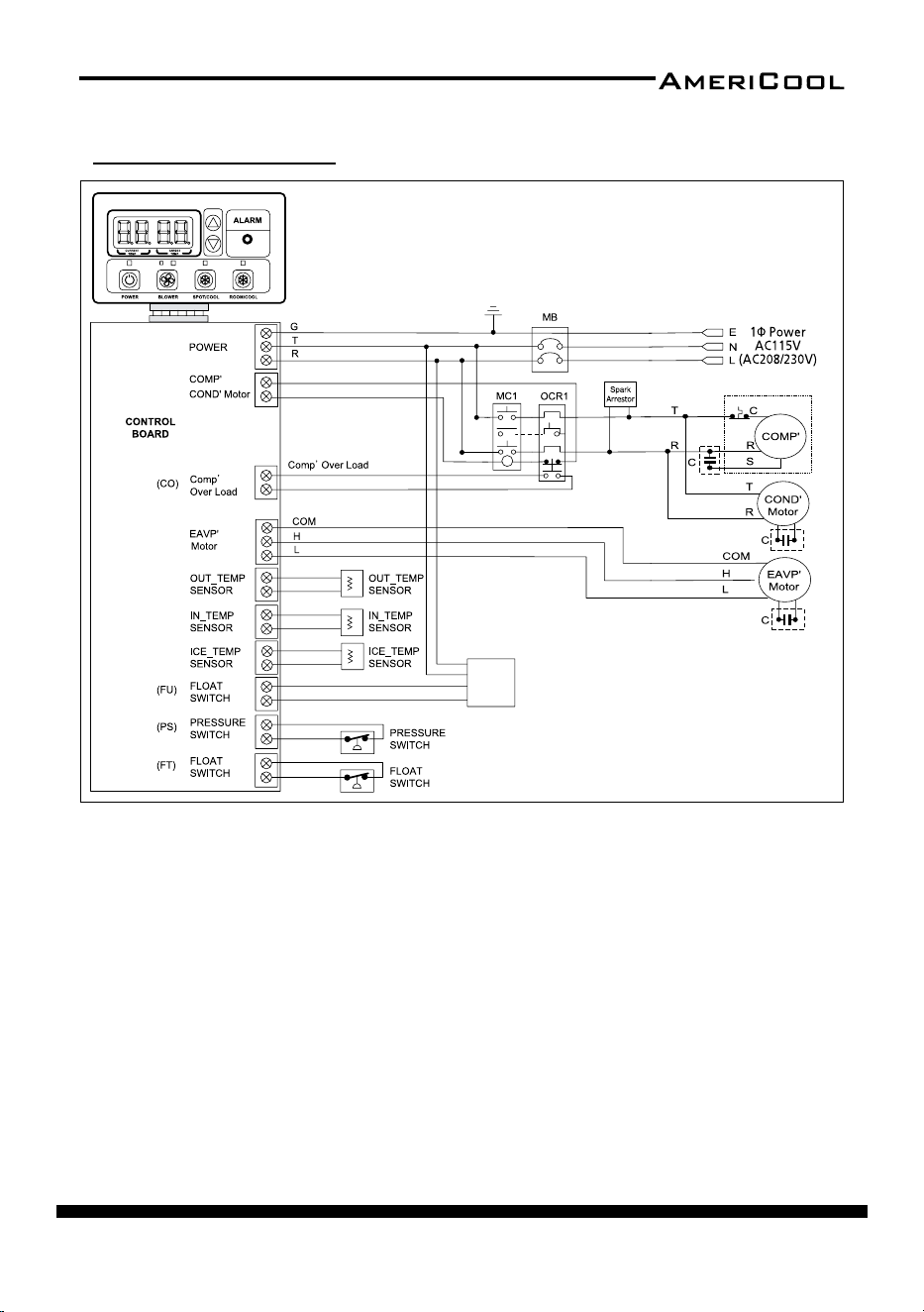
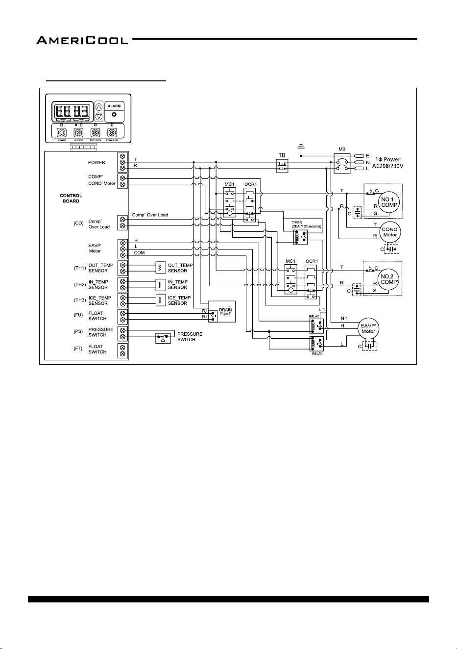
Wiring Diagram
(TH1)
(TH2)
(TH3)
DRAIN
PUMP
Figure 36 - Circuit Wiring Diagram (Models HPC-3000 / HPC-5000 / HPC-7000)
page 24
Owner’s Manual
HPC-3000 / WPC-4000 /HPC-5000 / WPC-7000 / WPC-9000 / WPC-15000
DRAIN
PUMP
(option)
POWER
1P AC115
POWER
1P AC115
Figure 37 - Circuit Wiring Diagram (Models WPC-4000 )

page 25
Owner’s Manual
HPC-3000 / WPC-4000 / HPC-5000 / WPC-7000 / WPC-9000 / WPC-15000
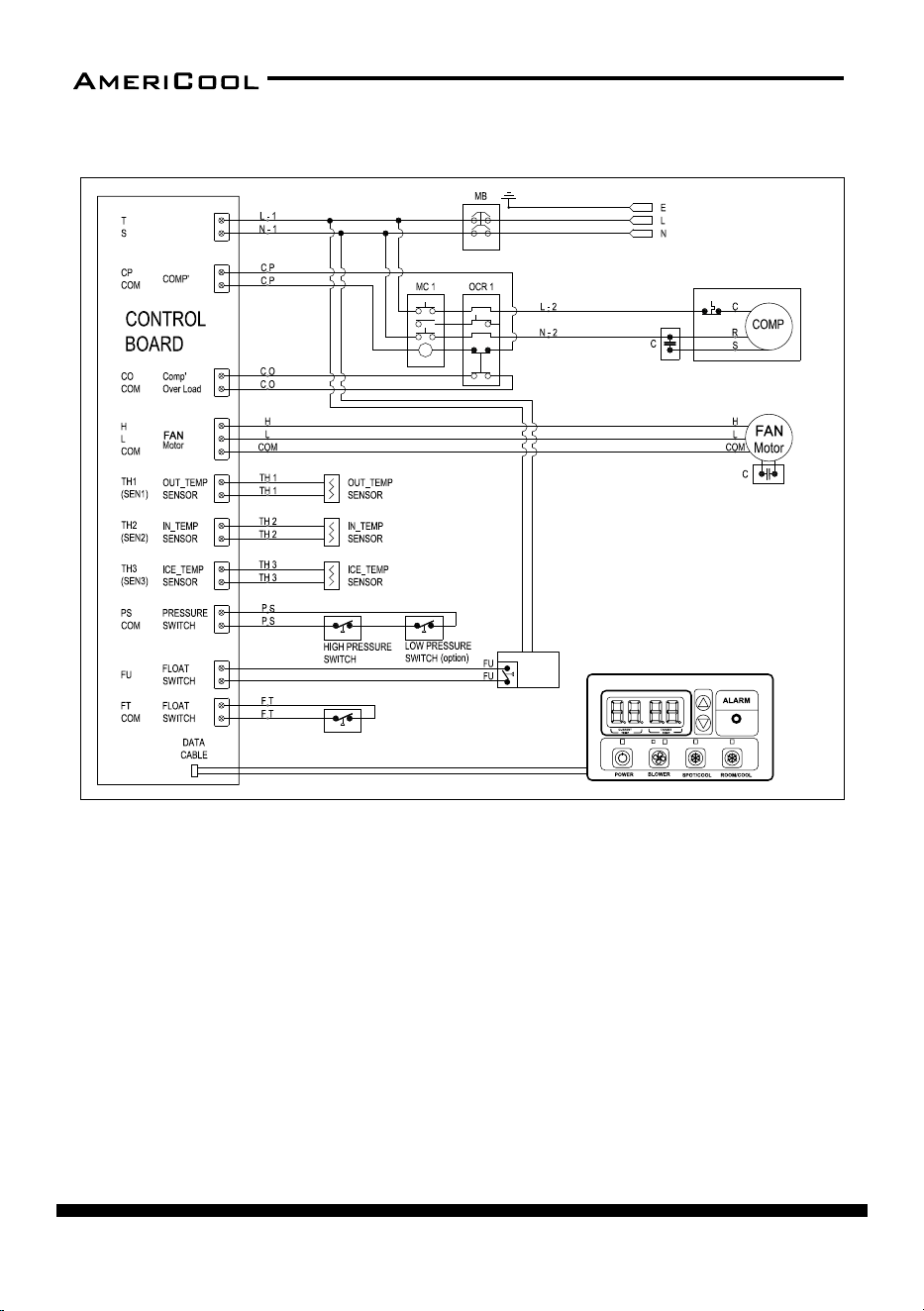
Figure 38 - Circuit Wiring Diagram (Models WPC-7000 / WPC-9000 )
DRAIN
PUMP
(option)
RELAY
RELAY
page 26
Owner’s Manual
HPC-3000 / WPC-4000 /HPC-5000 / WPC-7000 / WPC-9000 / WPC-15000
Figure 39 - Circuit Wiring Diagram (Models WPC-15000
)
Wiring Diagram

page 27
Owner’s Manual
HPC-3000 / WPC-4000 / HPC-5000 / WPC-7000 / WPC-9000 / WPC-15000
OBTAINING SERVICE
If the AmeriCool by Weltem Portable Air Condioner requires Service:
1. Use the TROUBLESHOOTING secon in this manual to eliminate obvious
causes.
2. Verify there are no circuit breakers tripped.
3. Call your dealer for assistance. If you cannot reach your dealer, or if they can
-
not resolve the problem, call AmeriCool by Weltem Portable Air Condi-
oner Technical Support at 562.231.7175. Please have the following informa-
on available BEFORE calling the Technical Support Department:
a. Your name and address.
b. The serial number of the unit.
c. Where and when the unit was purchased.
d. All of the model informaon about your
AmeriCool by Weltem Por-
table Air Condioner.
e. Any informaon on the failure, including LED’s that may or may not be
illuminated.
f. A descripon of the protected equipment, including model numbers if
possible.
SHIPPING LIST
• (1) PORTABLE AIR CONDIRIONER
• (1) Owner’s Manual
• (1) POWER CORD HOLDER
• (4) RUBBER STOPPERS (for HPC-5000)
• DISCHARGE / SUPPLY AIR DUCTS
(1) HPC-3000
(2) WPC-4000
(2) HPC-5000
(3) WPC-7000
(3) WPC-9000
(3) WPC-15000
• (1) EXHAUST FLANGE (for WPC-4000,7000,9000,15000)

page 28
Owner’s Manual
HPC-3000 / WPC-4000 /HPC-5000 / WPC-7000 / WPC-9000 / WPC-15000

page 29
Owner’s Manual
HPC-3000 / WPC-4000 / HPC-5000 / WPC-7000 / WPC-9000 / WPC-15000

page 30
Owner’s Manual
HPC-3000 / WPC-4000 /HPC-5000 / WPC-7000 / WPC-9000 / WPC-15000

page 31
Owner’s Manual
HPC-3000 / WPC-4000 / HPC-5000 / WPC-7000 / WPC-9000 / WPC-15000
LIMITED WARRANTY
AMERICOOL ONE-YEAR LIMITED WARRANTY. AMERICOOL BY WELTEM PORTABLE AIR
CONDITIONERS, MODELS COVERED IN THIS MANUAL, ARE WARRANTED BY AMERI
-
COOL TO THE ORIGINAL USER AGAINST DEFECTS IN WORKMANSHIP OR MATERIALS
UNDER NORMAL USE FOR ONE YEAR AFTER DATE OF PURCHASE. ANY PART WHICH IS
DETERMINED TO BE DEFECTIVE IN MATERIAL OR WORKMANSHIP AND RETURNED TO
AN AUTHORIZED SERVICE LOCATION, AMERICOOL DESIGNATES, SHIPPING COSTS PRE
-
PAID, WILL BE, AS THE EXCLUSIVE REMEDY, REPAIRED OR REPLACED BY AMERICOOL
OPTION. FOR LIMITED WARRANTY CLAIM PROCEDURES, SEE “PROMPT DISPOSITION”
BELOW. THIS LIMITED WARRANTY GIVE PURCHASERS SPECIFIC LEGAL RIGHTS WHICH
VARY FROM JURISDICT-
ION TO JURISDICTION.
LIMITATION OF LIABILITY. TO THE EXTENT ALLOWABLE UNDER APPLICABLE LAW, AMER
-
ICOOL LIABILITY FOR CONSEQUENTIAL AND INCIDENTAL DAMAGES IS EXPRESSLY DIS-
CLAIMED. AMERICOOL LIABILITY IN ALL EVENTS IS LIMITED TO AND SHALL NOT EXCEED
THE PURCHASE PRICE PAID.
WARRANTY DISCLAIMER. A DILIGENT EFFORT HAS BEEN MADE TO PROVIDE PROD
-
UCT INFORMATION AND ILLUSTRATE THE PRODUCTS IN THIS LITERATURE ACCURATELY;
HOWEVER, SUCH INFORMATION AND ILLUSTRATIONS ARE FOR THE SOLE PURPOSE OF
IDENTIFICATION, AND DO NOT EXPRESS OR IMPLY A WARRANTY THAT THE PRODUCTS
ARE MERCHANTABLE, OR FIT FOR PARTICULAR PURPOSE, OR THAT THE PRODUCTS WILL
NECESSARILY CONFORM TO THE ILLUSTRATIONS OR DESCRIPTIONS. EXCEPT AS PROVID
-
ED BELOW, NO WARRANTY OF AFFIRMATION OF FACT, EXPRESSED OR IMPLIED, OTHER
THAT AS STATED IN THE “LIMITED WARRANTY” ABOVE IS MADE OR AUTHORIZED BY
AMERICOOL.
Technical Advice and Recommendaons, Disclaimer. Notwithstanding any past pracce
or dealings or trade custom, sales shall not include the furnishing of technical advice or
assistance or system design. Americool assumes no obligaons or liability on account of
any unauthorized recommendaons, opinions or advice as to the choice, installaon or
use of products.
Product Suitability. Many jurisdicons have codes and regulaons governing sales, con
-
strucon, installaon, and/or use of products for certain purposes, which may vary from
those in neighboring areas. While aempts are made to assure that Americool products
comply with such codes, Americool cannot guarantee compliance, and cannot be re
-

32
PB
HPC-3000 / WPC-4000 /HPC-5000 / WPC-7000 / WPC-9000 / WPC-15000
Owner’s Manual
LIMITED WARRANTY
AmeriCool warrants all AmeriCool products to be free from defects in materials or workmanship,
under normal use and service, for a period of 12 months from the date of purchase to the end user
(original invoice must be provided). AmeriCool warrants that the compressor will be free from
defects in materials and workmanship for 12 months from the date of purchase to the end user.
AmeriCool’s obligaon under this warranty is limited to the repair or replacement at its opon,
of any part or parts, which, upon Ameriool’s examinaon are shown to be defecve, or at Ameri
-
Cool’s opon, the return of the purchase price to the purchaser.
Corr
econ of such defects by repair or replacement, or at AmeriCool’s opon, the return of the
purchase price shall constute fulllment of warranty obligaons to the purchaser. This warranty
does not cover defects or malfuncons which result from causes beyond AmeriCool’s control,
including, without limitaon,(i) unusal physical or electrical stress:(ii) accident, neglect, abuse,
misuse or other abnormal use; (iii) failure to perform roune maintenance in accordance with
AmeriCool’s recommended procedures; (iv)normal wear and tear; (v) repairs or aempted repairs
by an unauthorized person; (vi) modicaons or alteraons to the Products; (vii) use with parts or
devices not supplied or approved by AmeriCool (viii) improper installaon or service; (ix) shipping
damage to any units or spare parts during shipping. This includes and is not limited to compres
-
sors, evaporators and condenser coils. This warranty shall extend only to the original end-user and
shall
be void if any labels or other idenfying marks permanently axed to Products when shipped
by AmeriCool are removed, altered, defaced or obliterated.
TO THE EXTENT PERMITTED BY LAW, THIS WARRANTY, AS LIMITED HEREIN, SHALL BE IN LIEU OF
AND EXCLUSIVE OF ALL OTHER WARRANTIES, EITHER EXPRESSED OR IMPLIED, ON THE PART OF
AMERICOOL INC., OR WELTEM CO.,LTD. WHETHER ARISING FROM LAW, COURSE OF DEALING, US
-
AGE OF TRADE, OR OTHERWISE, INCLUDING WITHOUT LIMITATION ANY IMPLIED WARRANTY OF
MER
CHANT-ABILITY OR FITNESS OF A PARTICULAR PURP OSE OR ANY LIABILITY FOR COMMERCIAL
LOSSES BASED UPON NEGLIGENCE OR MANUFACTURER’S STRICT LIABILITY. EXCEPT AS EXPRESSLY
PROVIDED HEREIN,NEITHER AMERICOOL, INC., NOR WELTEM CO., LTD. WILL, IN ANY EVENT, BE
LIABLE FOR LOST PROFITS, COSTS OF PROCESSING,INJURY, GOODWILL, OR ANY OTHER CONSE
-
QUENTIAL DAMAGES OF ANY KIND ARISING FROM BREACH OF THIS WARRANTY.
Printed in January, 2021
Manufactured in Weltem Co., Ltd.,
154, Jayumuyeok 3-gil, Masanhoewon-gu, Changwon-City, Gyeongsangnam-do,
Republic of KOREA 51340 www.weltem.com
Distributed by Americool,Inc. In the USA (Tel.888-726-6158)
WWW.AMERICOOLLLC.COM