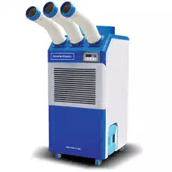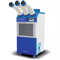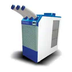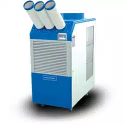

WPC-3000P, WPC-4000P, WPC-5000P
SERVICE MANUAL
Portable Air Condioners

2 page
Service Manual
WPC-3000P / WPC-4000P / WPC-5000P
Table of Contents
GENERAL DESCRIPTION................................................................................4
General air condioning system
Portable air condioning system
SPECIFICATIONS............................................................................................5
Exterior Dimension Diagram
Technical Specicaons
CONSTRUCTION............................................................................................7
Internal Structure
REFRIGERANT SYSTEM CONSTRUCTION.......................................................10
Compressor
Compressor lubricaon
Condenser
Capillary Tube
Evaporator
Accumulator
ELECTRICAL SYSTEM.....................................................................................15
Circuit Diagram
Control panel
Program Seng
Relay Board
Control Panel Input
Sensor Input
External Input signal Specicaon
Control Specicaons
Self-Diagnosc Codes
Compressor
Fan Motor
Temperature Sensor
Drain Tank Switch

page 3
Service Manual
WPC-3000P / WPC-4000P / WPC-5000P
ASSEMBLY.....................................................................................................31
Component parts
General Safety Informaon
Troubleshoong chart
DISASSEMBLY................................................................................................35
Disassembly
Control panel removal
Electrical parts and relay board removal
Fan motor removal
REFRGERANT SYSTEM REPAIR.......................................................................44
Brazing
Charging the System with R-410A Refrigerant
Connecon of gauge manifold
Evacuaon
Refrigerant Charging Work
4 page
Service Manual
WPC-3000P / WPC-4000P / WPC-5000P
GENERAL DESCRIPTION
General air condioning system
1) convenonal air condioners cool the enre enclosed environment.
2) They act as “heat exchangers”, and interior unit (evaporator) is used to blow cool
air into the interior and an exterior unit (condenser) is used to exhaust exchanged
heat to the outdoors.
Portable air condioning system
1) The WPC-3000P,WPC-4000P,WPC-5000P are a
spot cooler which directs cool air to parcular
areas or objects.
2) The WPC-3000P,WPC-4000P,WPC-5000P have
the following features.
3) The innovave design of the WPC-3000P,
WPC-4000P,WPC-5000P has resulted in one
compact unit, replacing the need for two
separate units.
4) With the whole cooling system built into
one compact unit, the WPC-3000P,WPC-
4000P,WPC-5000P require no piping and
can be easily transported and installed.
5) The WPC-3000P,WPC-4000P,WPC-5000P is
economical because it cools only the area or
objects which need to be cooled.
Condenser
Outdoor Unit
Evaporator
Indoor Unit
Exhaust Hot Air
Cooling Air
Filter
Filter
Intake air
(to Condenser)
Intake air
(to Evaporator)
page 5
Service Manual
WPC-3000P / WPC-4000P / WPC-5000P
SPECIFICATIONS
Exterior Dimension Diagram
WPC-3000P, 4000P, 5000P mm(Inch)
672.309 ( 26.468 )
158.2
( 6.228 )
88.5
( 3.48 )
343 ( 13.5039 )
520 ( 20.4724 )
113.559
( 4.4708 )
1006.5 ( 39.625 )
940 ( 37.007 )
767.393 ( 30.2123 )
103.709
( 4.083 )
Ø137.305
( 5.405 )
528.997 ( 20.8266 )
6 page
Service Manual
WPC-3000P / WPC-4000P / WPC-5000P
Specicaons Unit WPC-3000P WPC-4000P WPC-5000P
Cooling Capacity Btu/h 13,200 16,800 21,200
Power Supply
Phase Single Single Single
Volts 115 115 220V
Hertz 60 60 60
Power Consumpon Was 1,058 1,740 2,200
Rated Current Amps 9.2 15.8 10.9
EER Btu/Wh 11.0 9.8 8.8
Nema Plug Type 5-15P 5-20P 6-15P
Power Cord Gauge Awg 14 12 14
Power Cord Length 10 6 10
Dimensions (W x H x D) In.(mm) 20.5 x 27 x 41.1 ( 520 x 685 x 1044 )
Weight (Net / Gross) Lbs(kg)
178.6 / 194 lbs.
( 81 / 88 kg )
174.1 / 187.4 lbs.
( 79 / 86 kg )
187.6 / 211 lbs.
( 84 / 91 kg )
Condensate tank Gallons(Liters) 3.17 (12) 3.17 (12) 3.17 (12)
No. of Cool Air Outlets Pcs 2 2 2
Ambient temperature range ˚F(˚C) 64~113(18~45) 64~113(18~45) 64~113(18~45)
Seng temperature
(Room cool mode)
˚F(˚C) 64~86(18~30)
Seng temperature
(Spot cool mode)
˚F(˚C) 32~86(0~30)
Applicaon Area
(Room cool mode)
²(m²) 355 (33) 430 (40) 538 (50)
Refrigerant
Type R-410a R-410a R-410a
oz(g) 21.1 (570) 19.4 (550) 25 (710)
Design Pressure - Hi/Low Psig 465 / 160 465 / 250 484 / 148
Indoor Air Flow (High/Low) CFM(CMM)
405/ 345
(11.5 / 9.8)
470 / 400
(13.3 / 11.3)
560 / 465
(15.9 / 13.2)
Wheels
pcs 4 4 4
diameter 76 mm 76 mm 76 mm
Hot Air Duct Diameter In.(mm) 12 (300)
Maximum Duct Length (m) 50 (15)
Safety Devices
Compressor overload protector, An-freezing thermister, Full drain tank
switch, Automec restart (Power interrupon), Compressor me delay pro
-
gram, High pressure switch
Features
Temperature control, Self-diagnosc funcon, Two sppeds fan, Oponal drain
pump kit, Washable lters, ˚F(˚C) display
Technical Specicaons
page 7
Service Manual
WPC-3000P / WPC-4000P / WPC-5000P
SIZEDAT E
THIRD ANGLE
PROJECTION
22. 11. 16
CHECKED SCALEAPPROVEDDESIGNED
DWG.
NAME
MODEL
DWG NO.
이 도면은 Weltem의 자산으로 불법 유출시
관계법과 회사규정에 의해 처벌됨
Privileged & Confidential By Weltem.
N/S
하상률
Assembly Drawing
WPC-3000P
NO. PART NAME
WPC-3000P
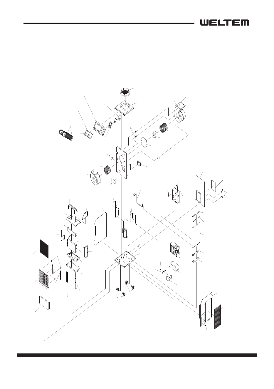
1 Bottom Base
2
Caster
Bottom Base
Caster
Caster
3
Cord Lock
Cord Lock
4
Barrier
Barrier
5
Cond Motor BKT
Cond Motor BKT
Cond Motor BKT
6
Motor Mount
7
Motor
Motor Mount
Motor
8
Cond Fan
9
Cond Scroll A
10
Cond Scroll B
Cond Fan
Cond Scroll A
Cond Scroll B
11
Eva Fan
12
Eva Scroll
13
14
Drain Pump Conector Cover
15
Pipe BKT A
16
Clamp
Eva Fan
Eva Scroll
Drain Pump Conector Cover
Pipe BKT A
Clamp
17
Drain Pump Conector
Drain Pump Conector
18
Cond Scroll Bridge
19
Control Box
Pipe BKT A
Clamp
Cond Scroll Bridge
Control Box
20
Compressor
21
Suction Pipe
Suction Pipe
22
Discharge Pipe
23
Cond Out Pipe
Compressor
Discharge
Pipe
Cond Out Pipe
24
Cond Cover Bottom
25
MFC Bottom BKT
26
Cond (MFC) Ass'Y
27
28
29
MFC Top Cover B
30
MFC Top Cover A
Cond Cover Bottom
MFC Bottom BKT
Cond (MFC) Ass'Y
MFC Top Cover B
MFC Top Cover A 31
LF Cover
LF Cover
32
Cond Filter
Cond Filter
33
Micro Switch
34
WT BKT B
35
WT BKT A
36
WT Guide
37
Water Tank
Micro Switch
WT BKT B
WT BKT A
WT Guide
Water Tank
38
RH Cover
39
WT Fix
RH Cover
WT Fix
40
Low Cover
41
Front Cover
42
Magnetic Catch
43
Front Cover Filter BKT
44
Eva Filter
45
Middle Base Filler
46
Middle Base
47
Drain Pan
48
Evaporator
49
Eva Top Cover
50
Eva Air Guide
51
Eva Top Guide
52
Back Cover
53
Control Box Cover
54
Power Cord Hanger
Back Cover
Control Box Cover
Power Cord Hanger
55
Top Base Cover
56
Cowl
57
Top Front Cover
58
Duct Base
59
Nozzle Ass'Y
60
Display Case
61
62
Display PCB
Display Case Cover
Top Base Cover
Cowl
Top Front Cover
Duct Base
Nozzle Ass'Y
Display
Case
Display
PCB
Display Case Cover
Eva LF Cover
Eva RH Cover
Eva Top BKT
Low Cover
Front Cover
Magnetic Catch
Front Cover
Filter BKT
Eva Filter
Middle Base Filler
Middle Base Filler
Middle Base
Drain Pan
Evaporator
Eva Top Cover
Eva Air Guide
Eva Top Guide
Eva LF Cover
Eva RH Cover
Eva Top BKT
(주)웰 템 WELTEM CO.,LTD
CONSTRUCTION
Internal Structure
WPC-3000P
8 page
Service Manual
WPC-3000P / WPC-4000P / WPC-5000P
SIZEDAT E
THIRD ANGLE
PROJECTION
22. 11. 16
CHECKED SCALEAPPROVEDDESIGNED
DWG.
NAME
MODEL
DWG NO.
이 도면은 Weltem의 자산으로 불법 유출시
관계법과 회사규정에 의해 처벌됨
Privileged & Confidential By Weltem.
N/S
하상률
Assembly Drawing
WPC-4000P
NO. PART NAME
WPC-4000P
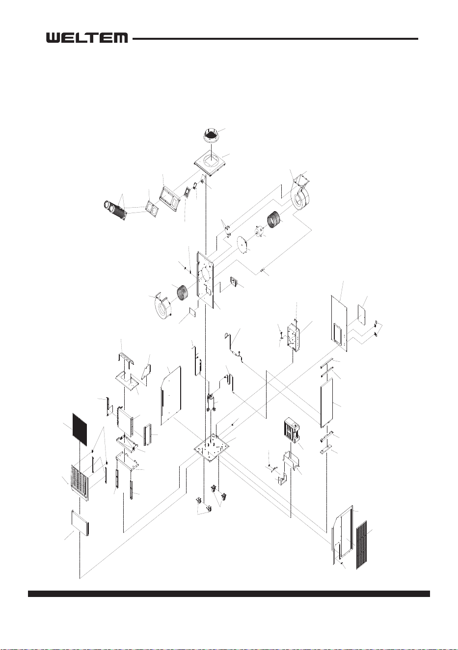
1 Bottom Base
2
Caster
Bottom Base
Caster
Caster
3
Cord Lock
Cord Lock
4
Barrier
Barrier
5
Cond Motor BKT
6
Motor Mount
7
Motor
8
Cond Fan
9
Cond Scroll A
10
Cond Scroll B
Cond Motor BKT
Cond Motor BKT
Motor Mount
Motor
Cond Fan
Cond Scroll A
Cond Scroll B
11
Eva Fan
12
Eva Scroll
13
14
Drain Pump Conector Cover
15
Pipe BKT A
Pipe BKT A
16
Clamp
17
Drain Pump Conector
Clamp
Eva Fan
Eva Scroll
Drain Pump
Conector Cover
Pipe BKT A
Clamp
Drain Pump Conector
18
Cond Scroll Bridge
19
Control Box
Cond Scroll Bridge
Control Box
20
Compressor
Compressor
21
Suction Pipe
Suction Pipe
22
Discharge Pipe
Discharge Pipe
23
Cond Out Pipe
Cond Out Pipe
24
Cond Cover Bottom
25
MFC Bottom BKT
Cond Cover Bottom
MFC Bottom BKT
26
Cond (MFC) Ass'Y
27
28
29
MFC Top Cover B
30
MFC Top Cover A
Cond (MFC) Ass'Y
MFC Top Cover B
MFC Top Cover A
31
LF Cover
LF Cover
32
Cond Filter
Cond Filter
33
Micro Switch
34
WT BKT B
35
WT BKT A
36
WT Guide
37
Water Tank
Micro Switch
WT BKT B
WT BKT A
WT Guide
Water Tank
38
RH Cover
39
WT Fix
RH Cover
WT Fix
40
Low Cover
Low Cover
41
Front Cover
42
Magnetic Catch
Front Cover
43
Front Cover Filter BKT
Magnetic Catch
Front Cover
Filter BKT
44
Eva Filter
Eva Filter
45
Middle Base Filler
46
Middle Base
47
Drain Pan
48
Evaporator
Middle Base
Filler
Middle Base
Filler
Middle Base
Drain Pan
49
Eva Top Cover
50
Eva Air Guide
51
Eva Top Guide
Eva Top Cover
Eva Air Guide
Eva Top Guide
52
Back Cover
53 Control Box Cover
54
Power Cord Hanger
Back Cover
Control Box Cover
Power Cord Hanger
55
Top Base Cover
56
Cowl
57
Top Front Cover
58
Duct Base
59
Nozzle Ass'Y
60
Display Case
61
62
Display PCB
Display Case Cover
Top Base Cover
Cowl
Top Front Cover
Duct Base
Nozzle Ass'Y
Display Case
Display
PCB
Display
Case Cover
Eva LF Cover
Eva RH Cover
Evaporator
Eva LF Cover
Eva RH Cover
-
(주)웰 템 WELTEM CO.,LTD
CONSTRUCTION
Internal Structure
WPC- 4000P
page 9
Service Manual
WPC-3000P / WPC-4000P / WPC-5000P
SIZEDAT E
THIRD ANGLE
PROJECTION
22. 11. 16
CHECKED SCALEAPPROVEDDESIGNED
DWG.
NAME
MODEL
DWG NO.
이 도면은 Weltem의 자산으로 불법 유출시
관계법과 회사규정에 의해 처벌됨
Privileged & Confidential By Weltem.
N/S
하상률
Assembly Drawing
WPC-4/5000P
NO. PART NAME
WPC-5000P
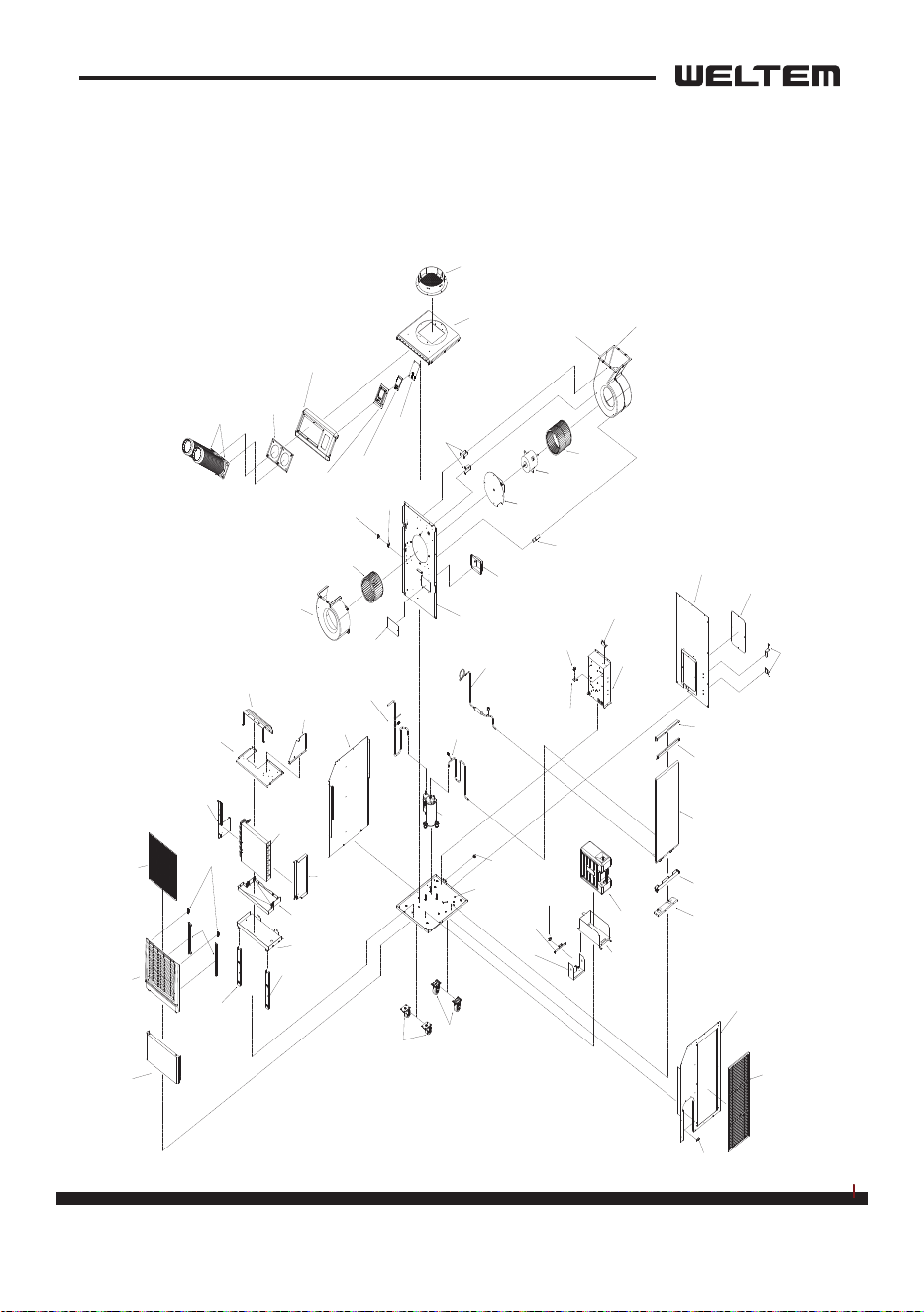
1 Bottom Base
2 Caster
Bottom Base
Caster
Caster
3 Cord Lock
Cord Lock
4
Barrier
Barrier
5 Cond Motor BKT
6 Motor Mount
7 Motor
8 Cond Fan
9 Cond Scroll A
10 Cond Scroll B
Cond Motor BKT
Cond Motor BKT
Motor Mount
Motor
Cond Fan
Cond Scroll A
Cond Scroll B
11 Eva Fan
12 Eva Scroll
13
14
Drain Pump Conector Cover
15
Pipe BKT A
Pipe BKT A
16
Clamp
Eva Fan
Eva Scroll
Drain Pump
Conector Cover
Pipe BKT A
Clamp
Clamp
17
Drain Pump Conector
Drain Pump Conector
18
Cond Scroll Bridge
Cond Scroll Bridge
19
Control Box
Control Box
20
Compressor
Compressor
21
Suction Pipe
22
Discharge Pipe
23
Cond Out Pipe
Suction Pipe
Discharge Pipe
Cond Out Pipe
24
Cond Cover Bottom
Cond Cover Bottom
25
MFC Bottom BKT
MFC Bottom BKT
26
Cond (MFC) Ass'Y
Cond (MFC) Ass'Y
27
28
29
MFC Top Cover B
MFC Top Cover B
30
MFC Top Cover A
MFC Top Cover A
31
LF Cover
LF Cover
32
Cond Filter
Cond Filter
33
Micro Switch
34
WT BKT B
35
WT BKT A
Micro Switch
WT BKT B
WT BKT A
36
WT Guide
WT Guide
37
Water Tank
Water Tank
38
RH Cover
39
WT Fix
RH Cover
WT Fix
40
Low Cover
41
Front Cover
42
Magnetic Catch
43
Front Cover Filter BKT
44
Eva Filter
45
Middle Base Filler
46
Middle Base
47
Drain Pan
48
Evaporator
49
Eva Top Cover
50
Eva Air Guide
51
Eva Top Guide
Eva Top Cover
Eva Air Guide
Eva Top Guide
52 Back Cover
53 Control Box Cover
54
Power Cord Hanger
Back Cover
Control Box Cover
Power Cord Hanger
55
Top Base Cover
Top Base Cover
56 Cowl
Cowl
57
Top Front Cover
58 Duct Base
59 Nozzle Ass'Y
60
Display Case
61
62
Display PCB
Display Case Cover
Top Front Cover
Duct Base
Nozzle Ass'Y
Display Case
Display PCB
Display Case
Cover
Eva LF Cover
Eva RH Cover
Low Cover
Front Cover
Magnetic Catch
Front Cover
Filter BKT
Eva Filter
Middle Base Filler
Middle Base Filler
Middle Base
Drain Pan
Evaporator
Eva LF Cover
Eva RH Cover
-
(주)웰 템 WELTEM CO.,LTD
CONSTRUCTION
Internal Structure
WPC- 5000P
10 page
Service Manual
WPC-3000P / WPC-4000P / WPC-5000P
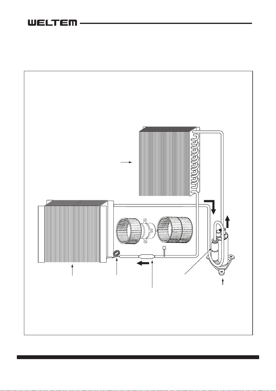
Compressor
Accumulator
Evaporator Capillary tube
Drier
Condenser
REFRIGERANT SYSTEM CONSTRUCTION
page 11
Service Manual
WPC-3000P / WPC-4000P / WPC-5000P
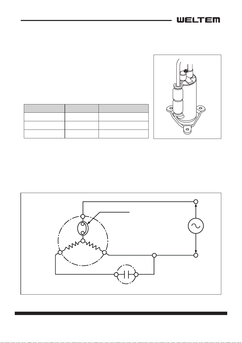
Compressor
The construcon of a rotary type compressor is divided into two mechanisms; the
drive mechanism (compressor motor), and the compression mechanism (compres
-
sor). When the rotor sha of the motor (drive mechanism) turns, the roller (com-
pression mechanism) rotates to compress the refrigerant.
To Condenser
Accumulator
Strainer
From Evaporator
Blade
Discharge Valve
Oil
Lubricato
r
Roller
Cylinder
Rotor
Stator
Terminal
12 page
Service Manual
WPC-3000P / WPC-4000P / WPC-5000P
Compressor operaon
1) Start of compression
1) The cylinder is lled with low pressure gas.
2) Since pressure in the discharge chamber
is higher than in the cylinder, the dis
-
charge valve is kept closed.
2) Sucon and compression
1) The pressure in the cylinder increases
gradually.
2) Refrigerant sucon begins on the suc
-
on side of the cylinder.
3) The discharge valve remains closed.
3) Discharge
1) The pressure in the cylinder exceeds that
in the discharge chamber, and the dis
-
charge valve opens.
2) On the sucon side, refrigerant sucon
connues.
4) Compleon of compression
1) When compression is completed, all of
the refrigerant has been drawn from the
sucon chamber.
2) Operaon then returns to step 1)(Start
of compression) and the above process
of sucon and compression connues
repeatedly in succession.
Blade
Discharge
Valve
Roller
Blade
Discharg
e
Valve
Roller
Blade
Discharge
Valve
Rolle
r
Blade
Discharge
Valve
Roller
page 13
Service Manual
WPC-3000P / WPC-4000P / WPC-5000P
Compressor lubricaon
The lubricaon system is comprised of a
hollow sha, an oil scraper mounted at the
end face, hollow sha, a sha journal (sha
bearing), and the lubricaon groove for the
sha journal.
The lubricaon groove is wider than the oil
hole. When the sha turns, oil is scraped
upward by the oil scraper along the inside
diameter of the hollow sha. The oil is fed
through the oil hole by centrifugal force,
then supplied to the lubricaon groove for
each sha journal, lubricang the bearing.
In this lubricaon system, oil enters into
each bearing separately and returns to the
oil reservoir. This system eecvely pre
-
vents bearing temperature increases, and
oers high reliability.
In addion, the specially treated sha jour
-
nal keeps the bearing from being
damaged during high temperature operaon.
Condenser
1) The condenser is a heat exchanger with
Louver ns.
2) Heat is given o and absorbed by air be
-
ing pulled across the condenser ns by
the axial fan. The air is then expelled
through the condenser air outlet.
Oil Feed Groove
Oil Hole
Oil Scrapper
Roller
Rotor
Cylinder
Hollow Sha
Eccentric Sha
14 page
Service Manual
WPC-3000P / WPC-4000P / WPC-5000P
Capillary Tube
The capillary tube is a long thin tube
that ulizes line ow resistance as an
expansion valve. The length and the
inner diameter of the capillary tube
are determined according to the
capacity of the refrigeraon system,
operang condions, and the amount
of refrigerant. The high pressure, high
temperature liquid refrigerant sent
from the condenser expands rapidly
as the refrigerant is sprayed out through the xed orice in the capillary tube. As a
result, the temperature and state of the refrigerant becomes low and mist-like, and
therefore evaporates easily.
Evaporator
The evaporator is a heat exchanger covered with slit
ns. Heat is removed from the air being pulled across
the evaporator by the centrifugal fan.
The resulng cool air is expelled through the cooling air
ducts.
Accumulator
The accumulator is mounted on the sucon gas pip-
ing between the evaporator and the compressor.
The accumulator separates the liquid refrigerant from
the gas refrigerant, allowing only the gas refrigerant to
enter the compressor. In the accumulator, sucon gas
isled into a cylindrical vessel where the speed of the
gas is decreased.
This process separates the refrigerant contained in
the gas by the force of gravity, causing the refrigerant to accumulate at the boom
of the vessel. As a result, the compressor is protected from possible damage caused
by liquid refrigerant intake.
High Temp./High Pressure
Liquid Refrigerant
Low Temp./Low Pressure
Gas and Liquid Mixtur
e
From Evaporator
To Compressor
page 15
Service Manual
WPC-3000P / WPC-4000P / WPC-5000P
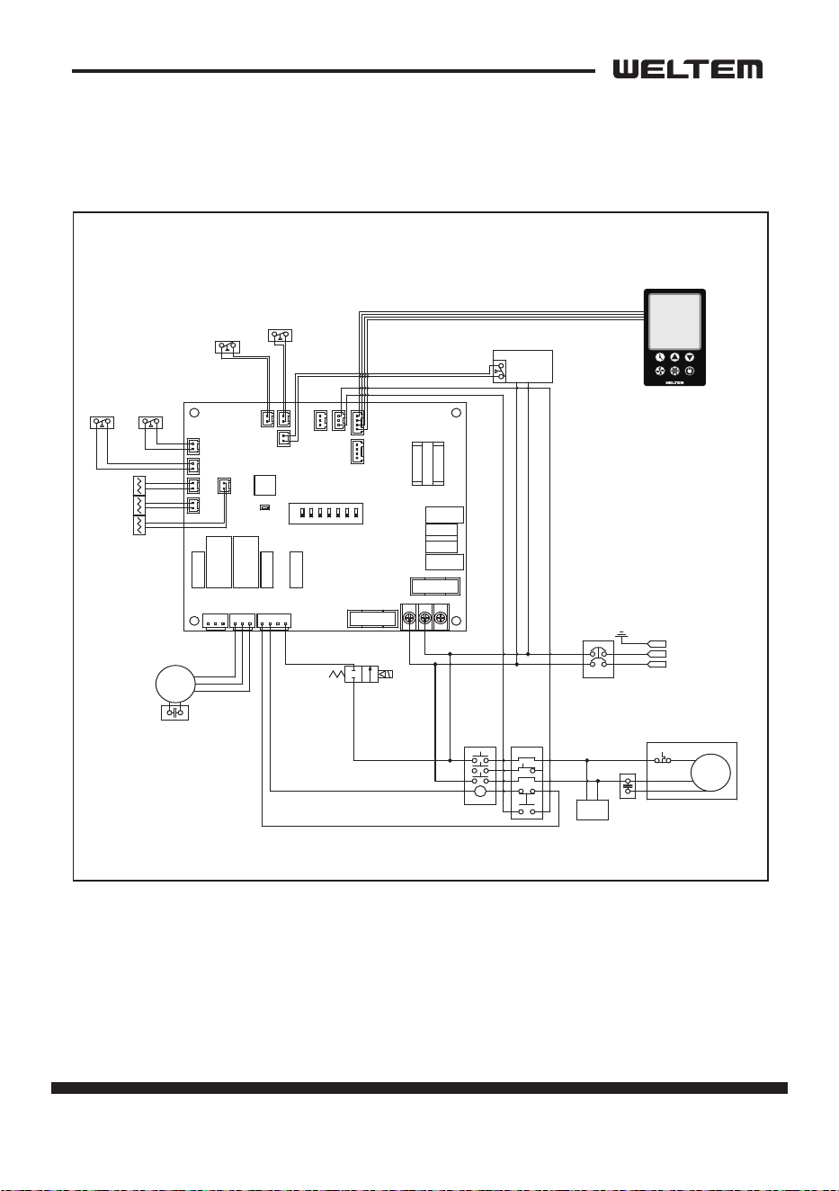
ELECTRICAL SYSTEM
Circuit Diagram
WPC-3000P,5000P
바이어명
Model WIRING DIAGRAM
1D R ICEN201202-01PART NO.
웰템
라벨 사이즈 136x116
적용모델
WPC-3/4/5 MP20.12.02 신규
작 성 검 토 확 인
수정사항
1
2
3
4
5
6
7
8
1
2
3
4
5
1. 재질 : 은무데드롱 25미크론
2. 인쇄방법: 씨링인쇄
3. 인쇄색상: 흑색 1도
4. 표면처리: 라미네이팅(OPP코팅)
5. 인쇄기준 : 도면 및 설계 제공 필름
6 외곽의 치수선(붉은선)은 인쇄후 절단선임.
136
116
WPC-3/4/5MP FC-S2.0
UP
COOL
POWERBLOWER
DOWN
TIMER
MCCB
E
MC 1 OCR 1
C
FAN'
MOTOR
C
C
R
S
COMP'
Spark
Arrestor
DRAIN
PUMP
(Option)
L - 2
N - 2
COM
L
H
COM
L
H
COM
CP
N-1
L-1
(PU) PU1
CP2
COM
EMC
L
H
(FUSE)
ALARM
COM NO NC
(CP)
CP1
HP1
(HP)
MOTOR
LCD-OUT
TH1
LP1
(LP)
TH2
TH3
ON
OFF
T (AC) S
R
(FUSE)
TH1
TH1
OUT_TEMP
SENSOR
TH3
TH3
ICE_TEMP
SENSOR
TH2
TH2
IN_TEMP
SENSOR
HIGH
PRESSURE
SWITCH
LOW
PRESSURE
SWITCH
(Option)
HP
HP
LP
LP
CO2
CO1 (CO)
EFO
CFO (RO)
FTEXT
FD
F LOAT
SWITCH
CO
COM
L
N
Power
1P AC 115V-60Hz
1P AC 208-230V,
50/60Hz
Power Remote
Control (Option)
FD
FD
FT
FT
EXT
EXT
Solenoid Valve
(Hot Gas Bypas)
(Option)
L-1
N - 1
16 page
Service Manual
WPC-3000P / WPC-4000P / WPC-5000P
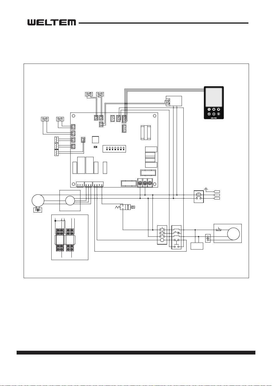
WPC-4000P
바이어명
Model WIRING DIAGRAM
1D R ICEN201202-02PART NO.
웰템
라벨 사이즈 136x116
적용모델
WPC-4000MP 미주20.12.02 신규
작 성 검 토 확 인
수정사항
1
2
3
4
5
6
7
8
1
2
3
4
5
1. 재질 : 은무데드롱 25미크론
2. 인쇄방법: 씨링인쇄
3. 인쇄색상: 흑색 1도
4. 표면처리: 라미네이팅(OPP코팅)
5. 인쇄기준 : 도면 및 설계 제공 필름
6 외곽의 치수선(붉은선)은 인쇄후 절단선임.
136
116
WPC-4MP FC-S2.0
UP
COOL
POWERBLOWER
DOWN
TIMER
MCCB
E
MC 1 OCR 1
C
C
R
S
COMP'
Spark
Arrestor
DRAIN
PUMP
(Option)
L - 2
N - 2
COM
L
H
COM
CP
N-1
L-1
(PU) PU1
CP2
COM
EMC
L
H
(FUSE)
ALARM
COM NO NC
(CP)
CP1
HP1
(HP)
MOTOR
LCD-OUT
TH1
LP1
(LP)
TH2
TH3
ON
OFF
T (AC) S
R
(FUSE)
TH1
TH1
OUT_TEMP
SENSOR
TH3
TH3
ICE_TEMP
SENSOR
TH2
TH2
IN_TEMP
SENSOR
HIGH
PRESSURE
SWITCH
LOW
PRESSURE
SWITCH
(Option)
HP
HP
LP
LP
CO2
CO1 (CO)
EFO
CFO (RO)
FTEXT
FD
F LOAT
SWITCH
CO
COM
L
N
Power
1P AC 115V-60Hz
Power Remote
Control (Option)
FD
FD
FT
FT
EXT
EXT
Solenoid Valve
(Hot Gas Bypas)
(Option)
C
FAN'
MOTOR
L
H
COM
Relay
"A"
N-1
Relay Relay
HL
N-1
(Motor측)
(PCB측)
Detail "A"
COM
HL
N-1
L - 1
N - 1
8
7
6
5
4
3
21
8
7
6
5
4
3
21
page 17
Service Manual
WPC-3000P / WPC-4000P / WPC-5000P
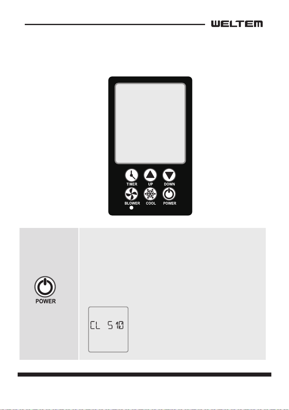
Operaon
CONTROL PANEL
· Press the power buon for 2 seconds to acvate the product.
· Press the power buon for 2 seconds while driving to stop
the product.
· Self-diagnosis will be performed to test for abnormalies,
aer marking “VER” for 3seconds when power is “ON”.
And the blowing is operated as “High”, and the compressor is
operated aer 1 minute.
← Example of “VER” sign when it’s ON
18 page
Service Manual
WPC-3000P / WPC-4000P / WPC-5000P
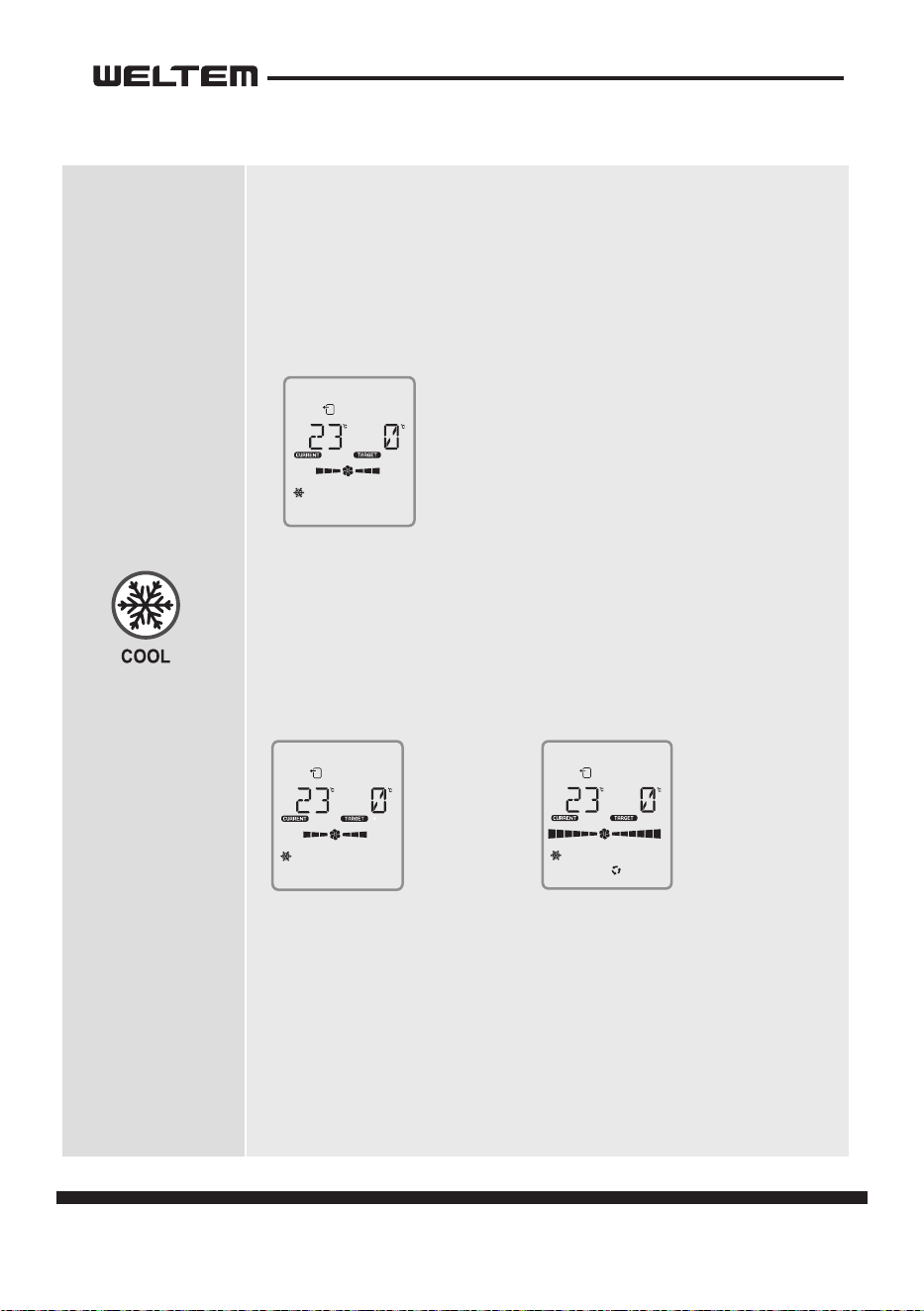
Cooling mode
1) Cooling mode
· The basic operaon is based on “out” control.
(discharge temperature TH1)
· On/o the operaon of the compressor. (COOL ↔ BLOWER)
· The set temperature cannot be changed and it operates which is
set to 0 degrees Celsius.
2) When blower is operating
· LOW → HIGH → AUTO It consists of three modes and operates
in circulation.
· LOW, HIGH, AUTOIn “LCD”, the middle wing of each mode rotate
and operate.
· AUTO MODE
- If the power source becomes “on” aer “o”,
it operates as “auto” and then as “high”
or “low” depending on the sensor value aer 3 seconds.
- The dierence between “current temp” and “target temp”
operates as “high” when it is 8 degrees Celsius or higher, and “low”
when it is 6 degrees Celsius or lower.
← Example of normal operation of
cooling mode.
←
LOW Examples
of moves.
←
AUTO Examples
of moves.
OUT
CON.
COOL
OUT
CON.
COOL
OUT
CON.
COOL
AUTO
page 19
Service Manual
WPC-3000P / WPC-4000P / WPC-5000P
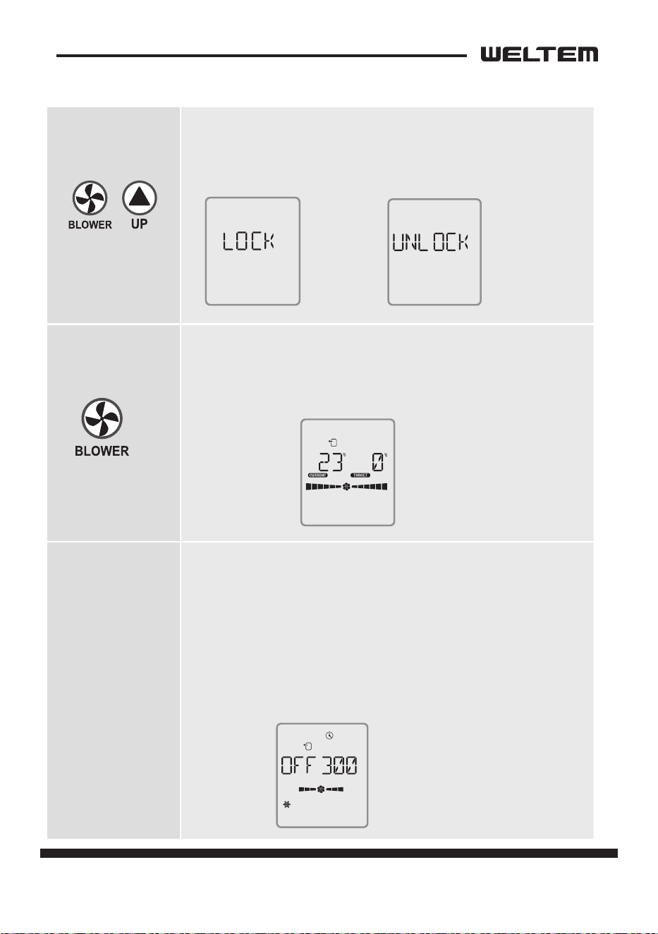
LOCK MODE
1) It is a mode that prevents the operation of the rest of the
buttons except for power.
· It can be operated and released by pressing for 2 seconds.
Blowing mode
1) The compressor does not operate, but only the blowing fan
operates.
· LOW → HIGH → AUTO It consists of three modes and operates
in circulation.
Reservaon mode
1) It’s the o reservaon mode.
· Press the ‘me’ buon for 2 seconds, select the ‘blower’ buon,
and select ‘on/o’, minutes as the ‘up/down’ buon.
· You can choose to make a reservaon for turning it on -> ON,
o -> OFF.
· UIt can be adjusted every 30 minutes with up/
down’ and up to 720 minutes (12 hours).
· If the ‘me+up’ buon or the me is “0”, the reservaon will
be canceled.
← Example of blowing.
← Example of displaying the
remaining time (minutes) during
“timer” operation during cooling.
←
Example
of a set-up.
←
Example of
releasing it.
OUT
CON.
OUT
CON.
COOL
TIMER
20 page
Service Manual
WPC-3000P / WPC-4000P / WPC-5000P
Program Seng
Change
Indica�on
Delay �me se�ng of COMP opera�on.
EX)If se�ng is 3mins, it takes 3mins to
be ON a�er COMP is OFF.
Devia�on temp se�ng.
Ex)It operates between 86℉(30℃) to 86℉(93.2℃)
(±35.6℉(±2℃)),
if dF se�ng is 35.6℉(2℃) under 89.6℉(32℃)(temp se�ng).
IC temperature se�ng
(Frost preven�on sensor)
Temperature Correc�on
Temperature Correc�on
1-5minutes, control is
available per 1 minute
30.2℉ ~ 23℉
(-1℃~ -5℃)
℉
℉
℉
Descrip�on the range of se�ng
Temperature Se�ng Program Se�ng
(Auto save when no se�ng is made in each mode)
How to save the se�ng
Target
Temperature
No se�ng for 5 seconds
to save automa�cally
Or press "cool" bu�on
to save
Keep
pressing more
than 2 seconds
Delay �me
Change
Devia�on
temperature
se�ng
Change
Temperature
dependence
Change
IC temperature
se�ng
Change
-14℉ ~ 50℉
(-10℃ ~ +10℃)
-14℉ ~ 50℉
(-10℃ ~ +10℃)
23℉ ~ 41℉
( -5℃ ~ +5℃ )
page 21
Service Manual
WPC-3000P / WPC-4000P / WPC-5000P
Failure to use the exact same fuse may result in damage to the
unit and/or components, and will also void the unit warranty.
CAUTION
Relay Board
The relay board contains the compressor and fan on relays, in addion to a step-
down transformer that converts the line voltage (WPC-3000P: 115 VAC, WPC-4000P:
115 VAC, WPC-5000P: 208/230 VAC) to 12V. This voltage is then converted from AC
to DC and used for relay coil acvaon. The 12 V (DC) power is sent to the control
panel assembly.
1) Power supply requirements
The WPC-3000P, WPC-4000P requires a single-phase 115 V, 60 Hz power supply.
The WPC-5000P require a single-phase 208/230 V, 60 Hz power supply.
2) Relay board fuse
The relay board fuse is the only serviceable component on the relay board assem
-
bly. This fuse provides protecon against damage to the step-down transformer.
The fuse must be replaced with the exact same part, or a suitable equivalent.
Specicaons : 3.15 A 250 VAC
22 page
Service Manual
WPC-3000P / WPC-4000P / WPC-5000P
3) Input Signal
The relay board receives inputs from the control panel, sensors, and external
devices to perform device control.
Symbol Indicaon Funcon Connector
ON/OFF Buon
If POWER BUTTON is pressed during operaon, unit
stops.
CON8
FAN Buon
Changes fan speed from LOW to HIGH when
pressed.
SET TEMP△Buon
Regulates temperature based on outlet cool air
temperature.
SET TEMP▽Buon
Regulates temperature based on inlet ambient air
temperature.
Symbol Type
Specicaon
Connector
Characterisc “Short”Detecon “Open”Detecon
TH1
OUT TEMP
SENSOR
10 k ohm at
77 °F (25 °C)
181 °F (83 °C) or
more
-29 °F (-34 °C) or
less
TH1
TH2
IN TEMP SEN
-
SOR
10 k ohm at
77 °F (25 °C)
181 °F (83 °C) or
more
-29 °F (-34 °C) or
less
TH2
TH3
ICE TEMP SEN
-
SOR
10 k ohm at
77 °F (25 °C)
181 °F (83 °C) or
more
-29 °F (-34 °C) or
less
TH3
Symbol Signal Specicaon Funcon Connector
CO Comp Overload
On: Between 10
to 20 mA at DC12
V (O: No signal)
On: Acvates “Defect control”
(Contact: Normally open) LED
shows “CO”, Output signal“ON”
CO
FD
External Pump
Failure
On: Between 10
to 20 mA at DC12
V (O: signal)
O: Acvates “Defect control”
(Contact: Normally open) LED
shows “FD”, Output signal“ON”
FD
HP Pressure Switch
On: Between 10
to 20 mA at DC12
V (O: signal)
On: Acvates “Defect control”
(Contact: Normally closed) LED
shows “HP” output signal “ON”
HP
FT Tank Full Switch
On: Between 10
to 20 mA at DC12
V (O: signal)
On: Acvates “Defect control”
(Contact: Normally closed) LED
shows “FT”, Output signal“ON”
FT
Control Panel Input
Sensor Input
External Input Signal Specicaon
page 23
Service Manual
WPC-3000P / WPC-4000P / WPC-5000P
Control Specicaons
1) EVAPORATOR FAN MOTOR
• When the BLOWER buon is pressed, the RL1/3 (fan motor HI/LOW) relay on the
relay board turns on, operang the fan.
Specicaons:
- RL1/3 (Fan motor HI-LOW) relay output: 10 A at AC 250 V
2) Compressor start control
• When the ON/OFF buon is pressed, the RL4 relay on the relay board turns on,
operang the compressor.
Specicaons:
- RL4 (Compressor On-O) relay output: 5 A at AC 250 V
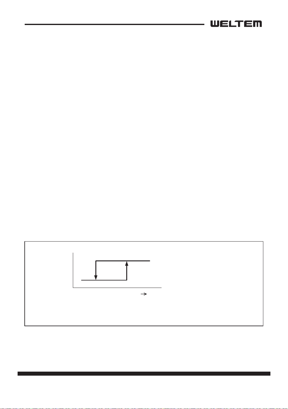
3) An-freeze control
• An-freeze controls turns the compressor on and o by turning the RL4 relay
on in accordance with the freeze protecon thermistor (TH3) temperature. As a
result, decreases in cooling performance due to frost buildup on the evaporator
are prevented.
• Compressor o condions: Freeze protecon thermistor (TH3) temperature ≤
28.4 °F (-2 °C)
• Compressor on (recovery) condions: TH3 (ICE temperature) ≥ 33.8 °F (1 °C)
ON
OFF
S3
28.4 °F
(-2 °C)
33.8 °F
(1 °C)
TH3 temperature
(Evaporator out temperature)
24 page
Service Manual
WPC-3000P / WPC-4000P / WPC-5000P
4) Compressor me delay control (compressor protecon)
Compressor protecon consists of a me delay program within the microproces
-
sor. This program prevents a heavy load from being applied to the compressor
motor when restarng the unit (room/cool mode or spot/cool mode) aer a very
short period of me. This “delay” is in eect any me the compressor is turned
on by either the POWER ON/OFF buon or ROOM/COOL or SPOT/COOL ON/OFF
buon.
Specicaons:
- Time Delay: 120 sec.
5) Automac restart and recovery funcon
• The microprocessor contains a feature that automacally restart the unit aer
power is lost and regained, and also has memory to store and recover operaon
status in the even of a power loss.
Status of memory during power interrupon
• When the input power is o, the status items below are saved in the memory.
- Running status (on or o)
- Operang mode: Cool mode or fan only mode
- Set temperature
- Temperature mode (°F or °C)
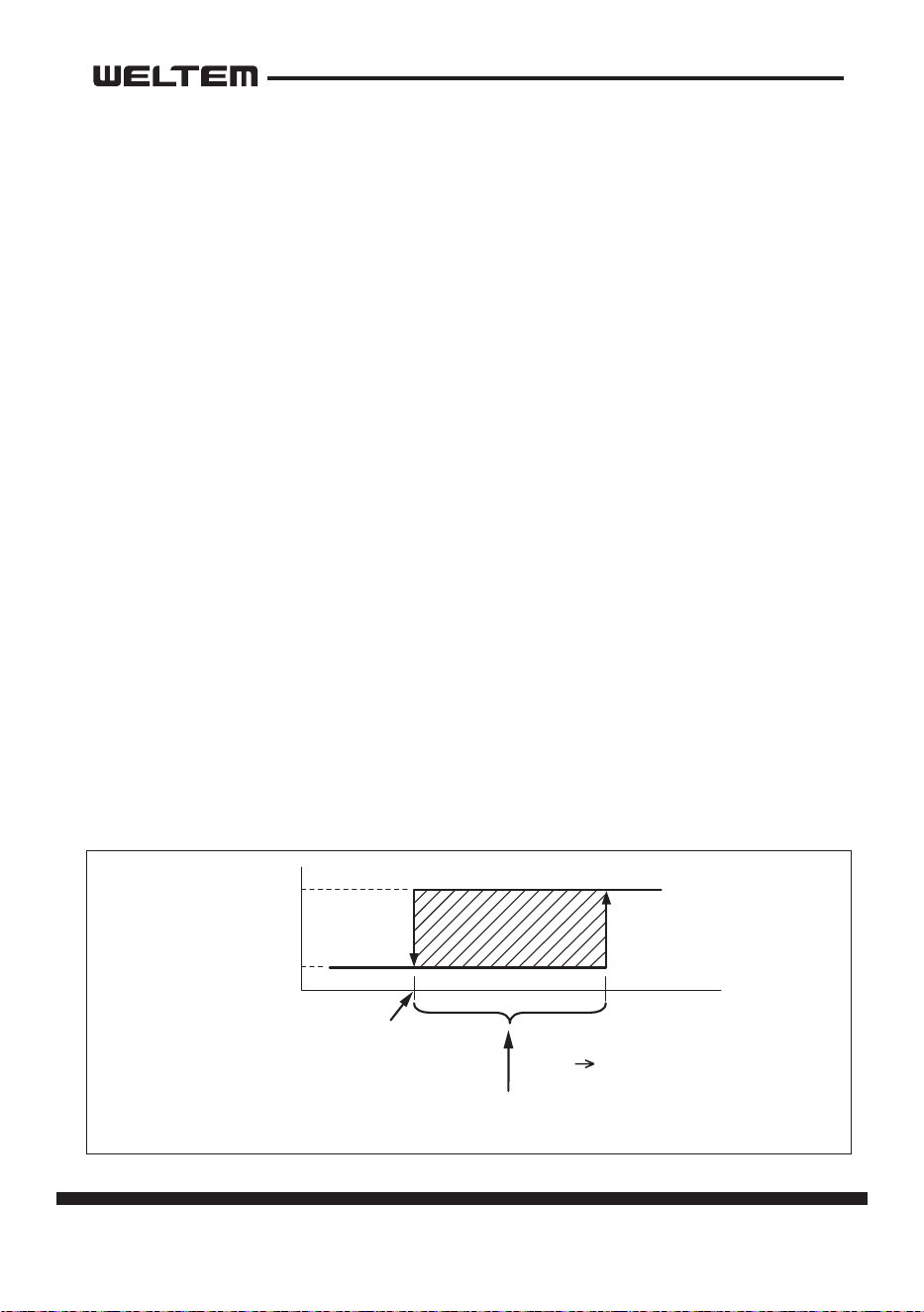
6) Temperature control
• During cool mode, temperature control changes the RL4 (compressor on/o)
relay status according to TH3 temperature in the available range(-4 °F to 140 °F
(-20 °C to 60 °C)).
ON
OFF
RL4
(Compressor Relay)
(Set Temp. -3 °F)
(Set Temp. -35.06 °F)
Set Temp
Inlet Air Temperature
When compressor operaon connues within this range
for more than 5 minutes, the RL4 relay stops.
page 25
Service Manual
WPC-3000P / WPC-4000P / WPC-5000P
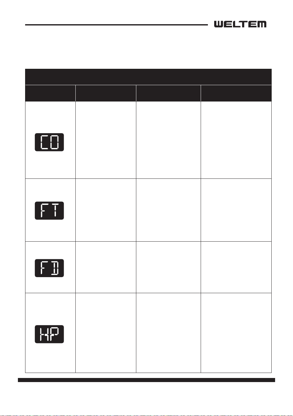
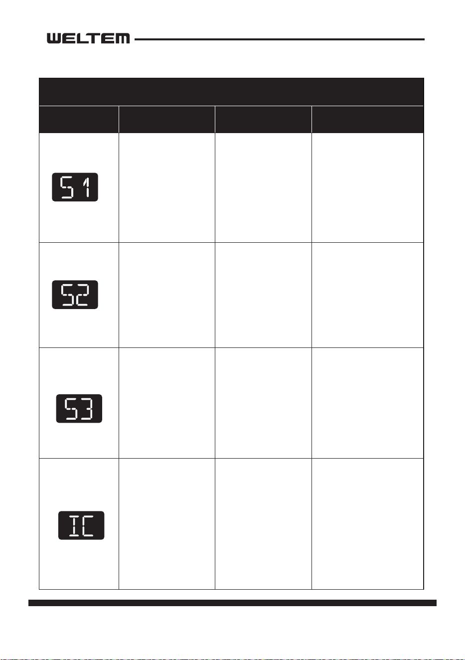
Self-Diagnosc Codes
Self-diagnosc codes are displayed on the Display Panel under the following
condions.
SELF-DIAGNOSTIC ALARM CODES
Alarm Display Problem Cause Correcve Acon
Compressor
overloaded
• Ambient tempera
-
ture is too high
• Unstable voltage
supply
• Defecve com
-
pressor
• Do not use the air
condioner if ambi
-
ent temperature is
higher than 45°C
(113°F)
• Contact a qualied
service agent
• Replace compressor
Condensate water
level alarm
Condensate tank is
full
• Empty the water
tank
• Aer installaon of
the water tank, press
the SPOT/COOL or
ROOM/COOL buon
to resume operaon
Drain pump alarm
Drain pump defec
-
ve or improper
hose connecon
(including kink or
blockage)
• Check the aconnec
-
on and hose
• Replace drain pump
Refrigerant high
pressure switch
• Blocked air lter
• Blocked / kinked
exhaust duct
• Ambient tempera
-
ture is too high
• Clean air lter
• Ensure exhaust duct
is not blocked /
kinked
• Do not use the air
condioner if ambi
-
ent temperature is
higher than 45°C
(113°F)
26 page
Service Manual
WPC-3000P / WPC-4000P / WPC-5000P
SELF-DIAGNOSTIC ALARM CODES
Alarm Display Problem Cause Correcve Acon
Abnormal temper
-
ature sensor value
TH1(Outlet)
temperature sen
-
sor has a loose or
broken connecon
Contact a qualied
service agent
Abnormal temper
-
ature sensor value
TH2(Inlet)
temperature sen
-
sor has a loose or
broken connecon
Contact a qualied
service agent
Abnormal temper
-
ature sensor value
TH3 (Prevenon
of Freeze) Sensor
open circuit or
poor
connecon.
Contact a qualied
service agent
Frost prevenon
sensor and Abnor
-
mal
temperature sen
-
sor value
• Indoor heat ex
-
changer temper-
ature too low
• TH3 temperature
sensor has a
loose or broken
connecon
• Do not use the air
condioner if ambi
-
ent temperature
is lower than 18°C
(64°F)
• Contact a qualied
service agent
page 27
Service Manual
WPC-3000P / WPC-4000P / WPC-5000P
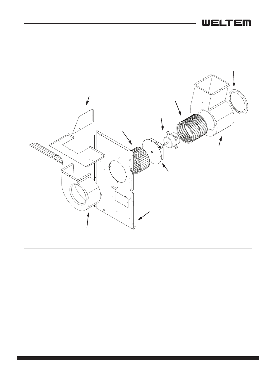
Compressor
1) Compressor motor
• The compressor motor is a single-phase motor
and is contained within the same housing as
the compressor.
Specicaons:
2) Compressor overload relay
• The compressor overload relay is used to protect the compressor motor.
The relay interrupts the ow of current when there is an overload condion and,
high temperature builds up in the compressor.
Rated Voltage CAPACITY
WPC-3000P 115V 3280W ±5%
WPC-4000P 115V 4170W ±5%
WPC-5000P 220V 5660W ±5%
Run capacitor
AUXMAIN
RS
C
COMP
R.
MO
TOR
Inner protector
28 page
Service Manual
WPC-3000P / WPC-4000P / WPC-5000P
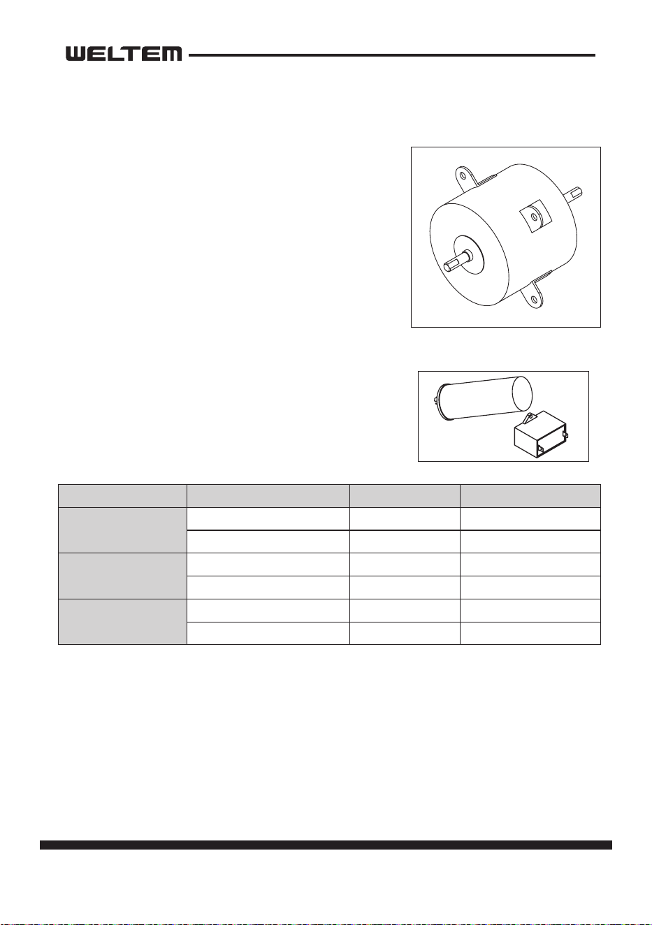
• The fan motor is a single phase, inducon type.
The motor rotates the fan on both the evapora
-
tor side and the condenser side at the same
me.
• The following table shows the specicaons of
the fan motor used for each model.
NOTE:An internal overload relay is used to protect
the fan motor. This relay is built into the fan motor
and interrupts the ow of current when there is
an over current situaon, or if abnormally high
temperature builds up in the fan motor.
Fan Motor
Capacitor
• The capacitor is used to improve the rotaonal power
of the fan motor and compressor at start up. The
specicaon for each capacitor is shown below.
Capacitor Rated Voltage Capacitance
WPC-3000P
Compressor 115V 55µF / 250VAC
Fan Motor 115V 25µF / 250VAC
WPC-4000P
Compressor 115V 60µF / 250VAC
Fan Motor 115V 25µF / 250VAC
WPC-5000P
Compressor 220V 45µF / 450VAC
Fan Motor 220V 8µF / 450VAC
page 29
Service Manual
WPC-3000P / WPC-4000P / WPC-5000P
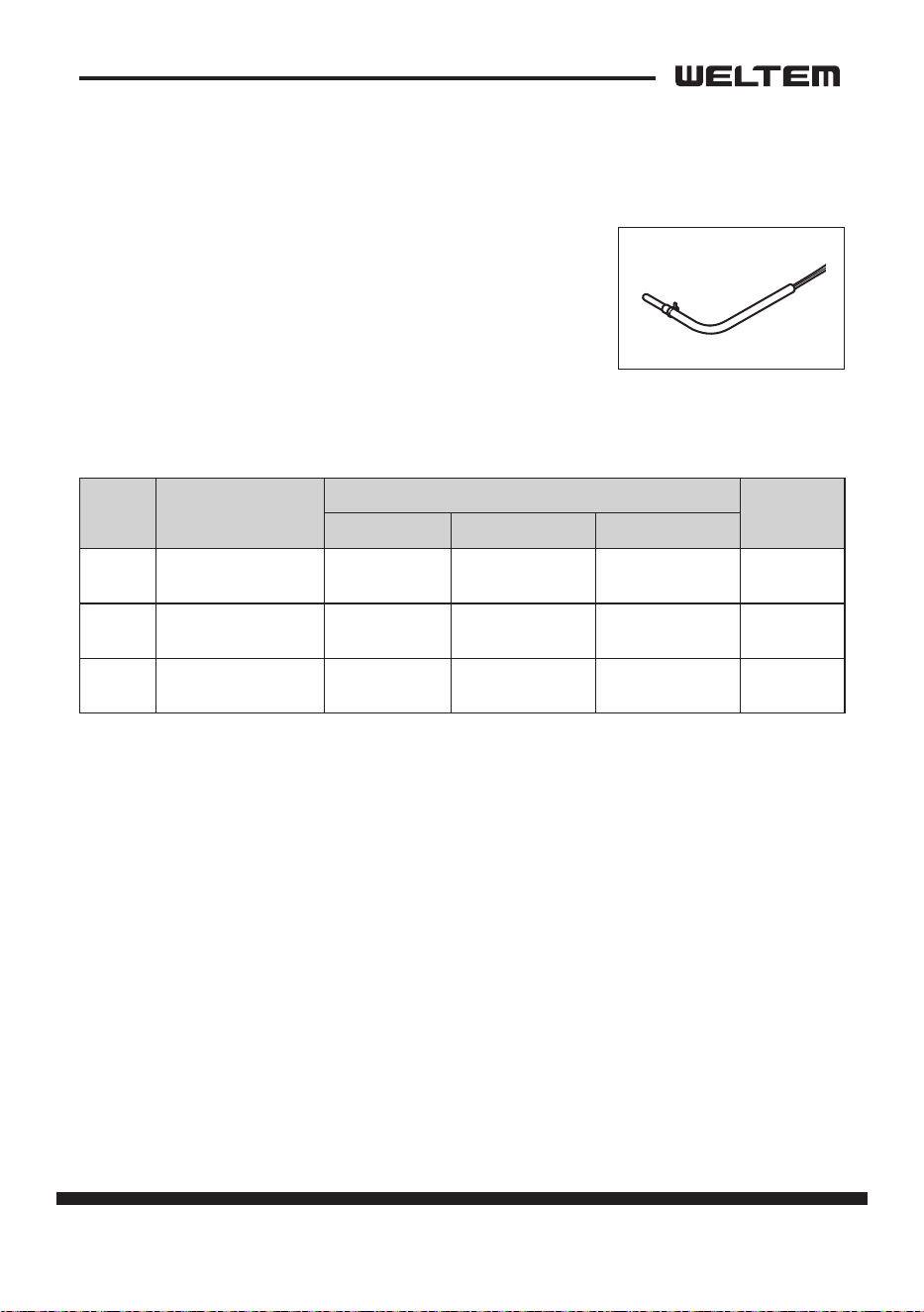
Temperature Sensor
• Outlet temp sensor (TH1) is installed on top of the
evaporator, and detects evaporator outlet temperature
as a resistance value.
• Inlet temp sensor (TH2) is installed in front of evapo
-
rator, and detects evaporator inlet temperature as a
resistance value.
• Ice temp sensor (TH3) is installed in the evaporator outlet piping, and detects low
temperature on the evaporator as a resistance value.
Symbol Type
Specicaon
Connector
Characterisc “Short”Detecon “Open”Detecon
TH1 OUT TEMP SENSOR
10 k ohm at
77 °F (25 °C)
181 °F (83 °C) or
more
-29 °F (-34 °C)
or less
TH1
TH2 IN TEMP SENSOR
10 k ohm at
77 °F (25 °C)
181 °F (83 °C) or
more
-29 °F (-34 °C)
or less
TH2
TH3 ICE TEMP SENSOR
10 k ohm at
77 °F (25 °C)
181 °F (83 °C) or
more
-29 °F (-34 °C)
or less
TH3
30 page
Service Manual
WPC-3000P / WPC-4000P / WPC-5000P
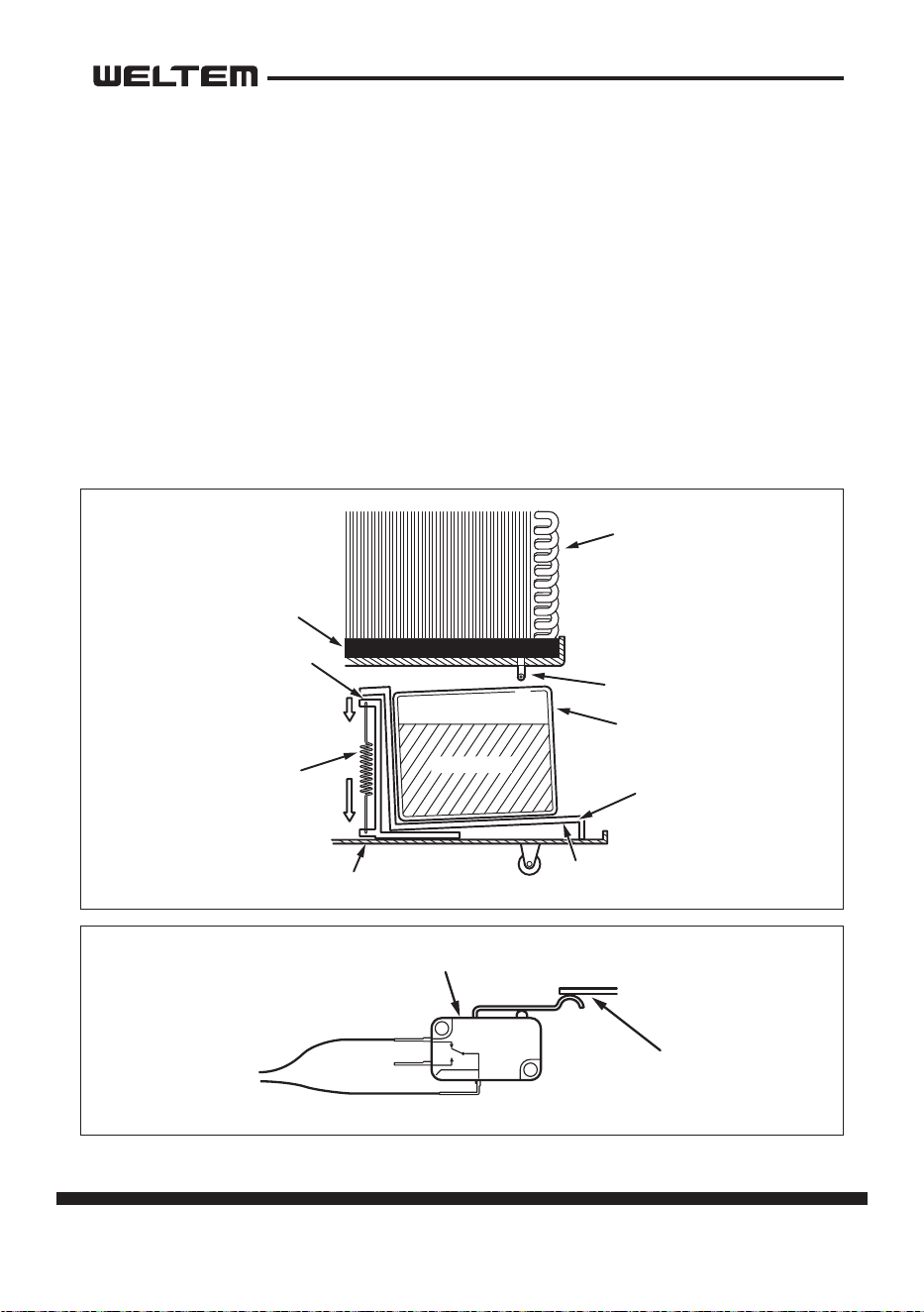
Drain Tank Switch
• The drain switch ac vates and stop the opera on of compressor motor
and fan motor when approximately 3.17 gal (12 L) of drain water
accumulates in the drain tank. At the same me, control panel display “FT”,
and compressor and fan opera ons stop. This system uses a 250 V, 0.1 A
ra ng micro switch for this func on.
• When approximately 3.17 gal (12 L) of drain water accumulates in the drain
tank, the drain tank base plate, which is supported at fulcrum (a), is pushed
down in the direc on of the arrow.
• When the drain tank base plate is forced down, “por on A”, located at the
top of the drain tank base plate, turns o micro switch contacts (1)-(2).
Evaporator
Drain Pan
Poron “A”
Spring
Drain Tube
Drain Water
Base
Drain Tank
Base Plate
a
Full Drain Switch
Poron “A
”
Rela
y
Boar
d
1
2
3
NC
COM
NO
C (1)
NC (2)
page 31
Service Manual
WPC-3000P / WPC-4000P / WPC-5000P
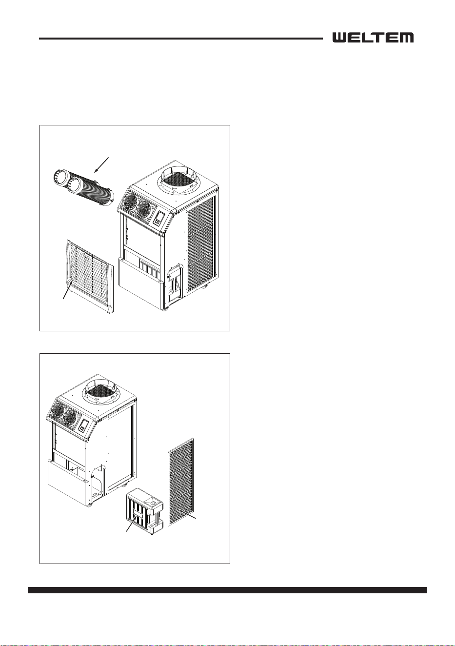
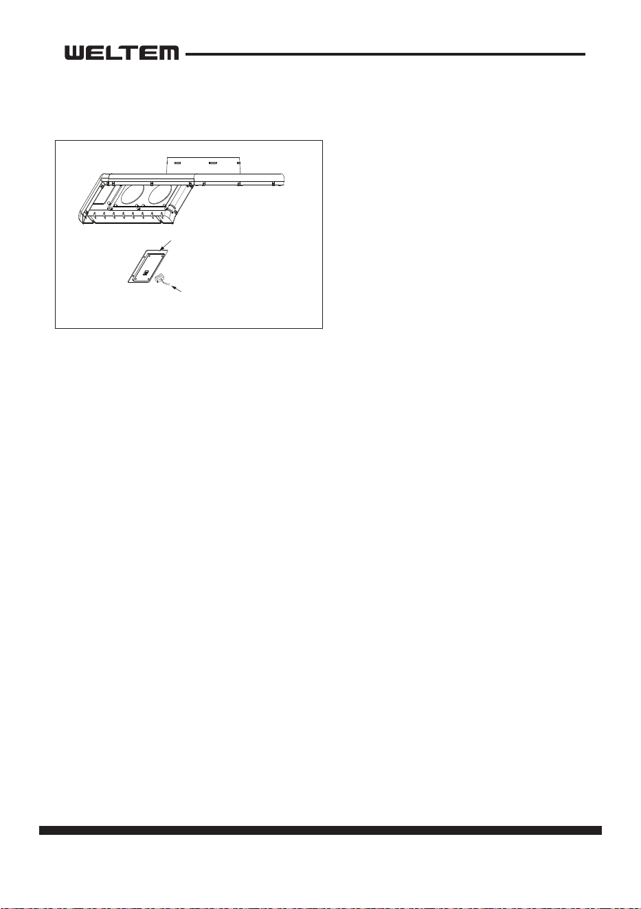
ASSEMBLY
Figure 1
Figure 3 Figure 4
Figure 5
Figure 6
Figure 2
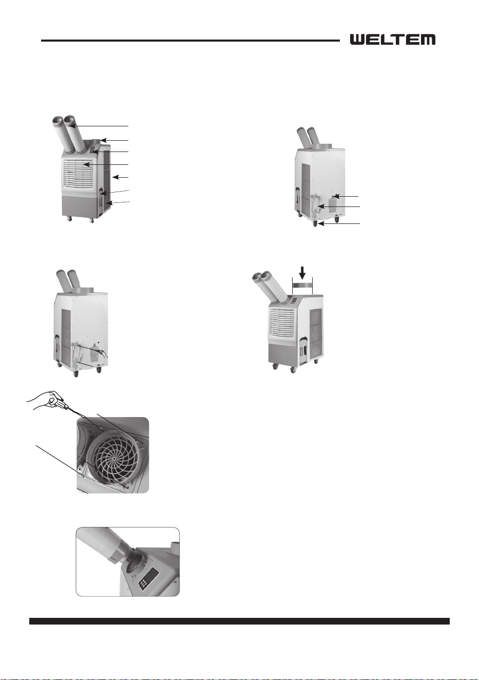
Cool air outlet hose
Top fan exhaust ange
Display / Control board
Evaporater / lter
Condenser / lter
Guide bar for condensate water
tank
Electrical access panel
Power cord holder
Caster
Condensate water tank (Water level is
sensed, and the unit opera on is stopped
when tank is full. An alarm will be
displayed. Empty the tank and replace to
resume opera on)
1. Take out the cord holder from
the accessory box.
2. Place the cord holder on the
back side of air condi oner.
3. Use screws (enclosed inside
of accessory box with cord holder)
to install the cord holder on the
air condi oner as shown in Figure 3.
1. Remove cool air outlet hose(s) from carton.
2. Place the cool air outlet hose(s) on the front top of air condi oner.
3. Use screws (enclosed inside of box with cool air outlet hose(s) to install
the cool air outlet hose(s) on the air condi oner as shown in Figure 5.
By applying a detachable duct that can be easily inserted by
turning it around at once, it is easy to a ach and detach,
adding convenience to air condi oner management.
1. Remove the top fan exhaust
ange from carton.
2. Place the top fan exhaust ange
on the top of air condi oner.
3. Use screws (enclosed inside
of box with the top fan exhaust
ange) to install the top fan
exhaust ange on air condi oner
as shown in Figure 4.
POWER CORD HOLDER
DISCHARGE DUCTS/SUPPLY AIR DUCT
CONVENIENT DETACHABLE DUCT
TOP FAN EXHAUST FLANGE
Front and Right side View Back and Le side View
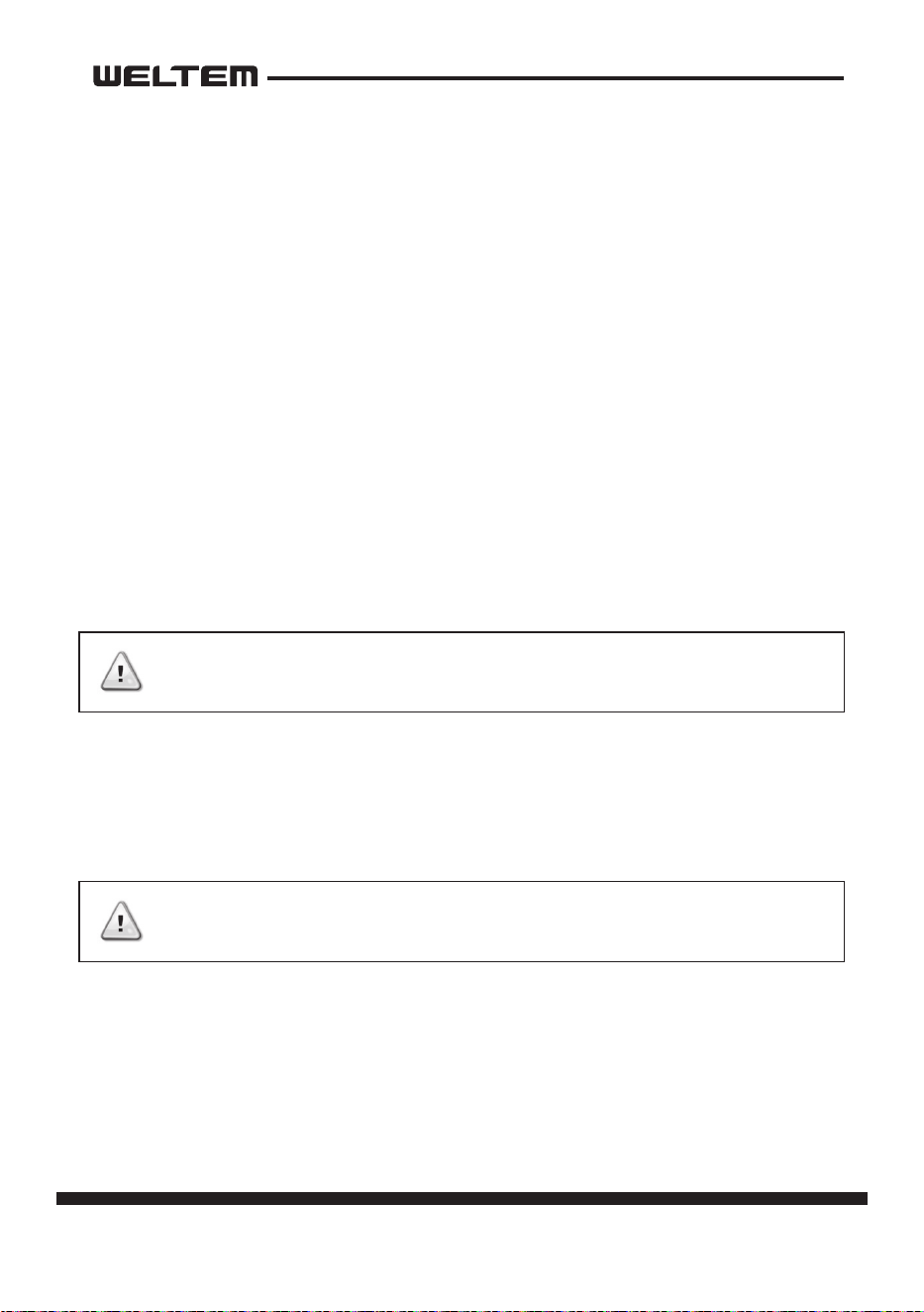
Component parts
32 page
Service Manual
WPC-3000P / WPC-4000P / WPC-5000P
General Safety Informaon
Please read this manual carefully for instrucons on correct installaon and usage.
Please read all safeguards.
1. Transport and store the unit in an upright posion only. Leave unit in an upright
posion for at least 3 hours before rst use.
2. Always place the unit on an even, level surface.
3. Ensure the unit is connected to a grounded power supply of the correct rang /
capacity.
4. The unit will cool when the room temperature is between 18°C (64.4°F) ~
45°C(113°F) depending on the thermostat seng.
5. DO NOT use this unit for funcons other than those described in this instrucon
manual.
6. DO NOT lt the unit.
7. DO NOT cover or obstruct the unit’s inlet and outlet grilles.
8. DO NOT use the unit in areas where it will be exposed to rain or water.
9. NEVER unplug the unit while it is operang.
10. DO NOT place any foreign objects on the unit.
11. DO NOT operate the unit with wet or damp hands.
12. DO NOT allow chemical substances to come into contact with the unit.
13. DO NOT operate the unit in the presence of ammable substances or vapors
such as alcohols, pescides, gasoline, etc.
14. DO NOT use the plug to start and to stop the unit. Always use the control panel
to start and to stop the unit.
15. Always turn o the unit when it is not in use and unplug the power plug from
the electrical outlet.
16. Always turn the unit o and unplug the main power plug from the electrical
outlet before cleaning, moving or performing maintenance.
DO NOT use the unit in wet environments, such as
a laundry room, to avoid the risk of electrical shock.
DO NOT operate the unit in explosive or ammable
environments.
WARNING
WARNING
page 33
Service Manual
WPC-3000P / WPC-4000P / WPC-5000P
17. AVOID the use of adapter plugs or extension cords. If it is necessary to use an
extension cord or an adapter plug to operate the unit, ensure that they are
correctly rated for the applicaon. Consult a local qualied electrician and all
local electrical codes to ensure proper setup. Any extension cord used with this
device must be rated for a minimum of 15A.
18. DO NOT unplug the unit by pulling on the electrical cord. Keep electrical cord
away from heat sources and always completely unroll the cord to avoid over
-
heang. If the power cord becomes damaged, a qualied service agent, quali-
ed electrician, or similarly qualied person must replace it, in order to avoid a
hazard or shock.
19. The lters must be used with the product at all mes. When the lters are
removed for cleaning, always ensure that the unit has been turned o and
unplugged from the electrical outlet.
20. Regularly clean the lters to maintain eciency. If the lters are not cleaned
regularly, the units output performance and eciency will decline and energy
consumpon will increase.
21. DO NOT operate the unit with a damaged power cord or plug, aer it malfunc
-
ons, has been dropped or damaged.
22. Only use in the upright posion on an even, at surface. Unit must be posi
-
oned at least 24 inches (60 cm) from the nearest object in any direcon.
23. Stop operaon immediately if abnormal noise or odor is noced. Contact a lo
-
cal service center.
24. Appliance is not to used by children or persons with reduced physical, sensory
or mental capabilies, or lack of experience and knowledge, unless they have
been given supervision or instrucon.
25. Children being supervised not to play with appliance.
26. That the appliance shall be installed in accordance with naonal wiring regula
-
ons.
27. If the supply cord is damaged, it must be replaced by the manufacturer, its ser
-
vice agent or similarly qualied persons in order to avoid a hazard.
SAVE THESE INSTRUCTIONS
DO NOT operate a unit with a damaged power cord.
WARNING
34 page
Service Manual
WPC-3000P / WPC-4000P / WPC-5000P
Troubleshoong chart
Symptom Possible Cause(s) Correcve Acon
Water leakage
High water level in conden
-
sate tank
1. Remove blockage from
drain hose
2. Remove any object stuck
undeerneath of the black
panel nuder the water tank
The unit doesn’t work
1. Check the power supply to
verify that power is avail
-
able to the unit
2. Verify that the power cord
is connected
1. Reset the circuit breaker
and restart the unit
2. Connect power cord
No cold air ows from the
cold air outlet
1. Ambient air cannot be
properly cooled if the lter
is dirty and not regularly
cleaned
2. Compressor will not work if
the unit isturned o and on
quickly.
3. The ambient air tempera
-
ture may be too high
1. Clean the lter
2. Wait 2 minutes aer unit
is turned o before turning
the unit back on.
3. The temperature of the
compressor can be higher
when the ambient tem
-
perature is too high. The
compressor will not work
unless the ambient air
temperature is within the
acceptable operang range
of the unit
Water ow can be heard aer
compressor shuts o
No cause
Common to hear coolant
owing aer unit shuts o
Alarm displays “FT” with less
than half of condensate water
in the tank
Spring is possibly broken
Spring is possibly broken Replace a new spring
page 35
Service Manual
WPC-3000P / WPC-4000P / WPC-5000P
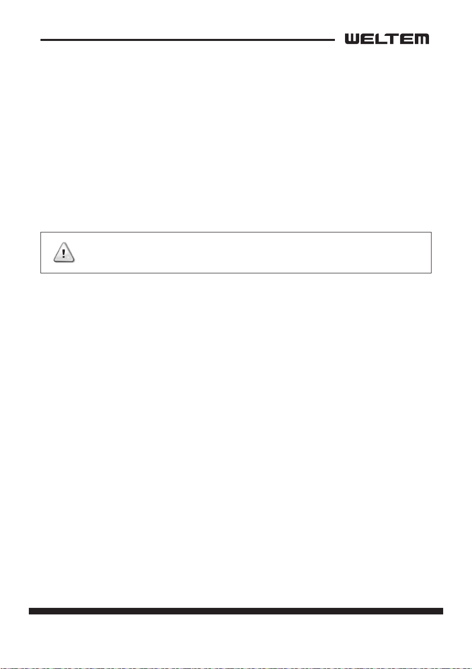
DISASSEMBLY
Disassembly
1) Unplug the product before
disassembly (For Safety)
2) Turn the cooling air ducts to remove
them.
3) Remove two (2) support lines and
remove front panel.
4) Remove the drain tank.
5) Li the cond lter slightly to
remove it.
Front Cover
Water Tank
Cond Filter
Cooling Air Duct
Cowl
Top Base Cover
Top Front Cover
Low Cover
Back Cover
RH Cover
LF Cover
Screws (6)
Screws (6)
Screws (15)
Screws (3)
Screws (12)
Screws (4)
Screws (3)
Screws (9)
Screws (4)
Front Cover
Water Tank
Cond Filter
Cooling Air Duct
Cowl
Top Base Cover
Top Front Cover
Low Cover
Back Cover
RH Cover
LF Cover
Screws (6)
Screws (6)
Screws (15)
Screws (3)
Screws (12)
Screws (4)
Screws (3)
Screws (9)
Screws (4)
36 page
Service Manual
WPC-3000P / WPC-4000P / WPC-5000P
Front Cover
Water Tank
Cond Filter
Cooling Air Duct
Cowl
Top Base Cover
Top Front Cover
Low Cover
Back Cover
RH Cover
LF Cover
Screws (6)
Screws (6)
Screws (15)
Screws (3)
Screws (12)
Screws (4)
Screws (3)
Screws (9)
Screws (4)
Front Cover
Water Tank
Cond Filter
Cooling Air Duct
Cowl
Top Base Cover
Top Front Cover
Low Cover
Back Cover
RH Cover
LF Cover
Screws (6)
Screws (6)
Screws (15)
Screws (3)
Screws (12)
Screws (4)
Screws (3)
Screws (9)
Screws (4)
7) Take out the six (6) screws,
and then remove the Cowl panel.
6) Take out the twelve (12) screws,
and then remove the back cover
panel.
Front Cover
Water Tank
Cond Filter
Cooling Air Duct
Cowl
Top Base Cover
Top Front Cover
Low Cover
Back Cover
RH Cover
LF Cover
Screws (6)
Screws (6)
Screws (15)
Screws (3)
Screws (12)
Screws (4)
Screws (3)
Screws (9)
Screws (4)
8) Take out the twenty one (21) screws,
and then remove the top cover
panel.
page 37
Service Manual
WPC-3000P / WPC-4000P / WPC-5000P
10) Take out the two (2) screws.
Unfasten two (2) screws to a half
point and then remove the low
cover panel.
9) Unfasten the connector from the
control panel and then remove the
front panel.
Front Cover
Water Tank
Cond Filter
Cooling Air Duct
Cowl
Top Base Cover
Top Front Cover
Low Cover
Back Cover
RH Cover
LF Cover
Screws (6)
Screws (6)
Screws (15)
Screws (3)
Screws (12)
Screws (4)
Screws (3)
Screws (9)
Screws (4)
LOW COVER 제거
TOP COVER - DISPLAY 분리
Connector
Connector
Control panel
Control panel
Screws (4)
11) Take out the Nine (9) screws,
and then remove the right-side
panel.
Front Cover
Water Tank
Cond Filter
Cooling Air Duct
Cowl
Top Base Cover
Top Front Cover
Low Cover
Back Cover
RH Cover
LF Cover
Screws (6)
Screws (6)
Screws (15)
Screws (3)
Screws (12)
Screws (4)
Screws (3)
Screws (9)
Screws (4)
Front Cover
Water Tank
Cond Filter
Cooling Air Duct
Cowl
Top Base Cover
Top Front Cover
Low Cover
Back Cover
RH Cover
LF Cover
Screws (6)
Screws (6)
Screws (15)
Screws (3)
Screws (12)
Screws (4)
Screws (3)
Screws (9)
Screws (4)
12) Take out the Four (4) screws, and
then remove the le-side panel.
38 page
Service Manual
WPC-3000P / WPC-4000P / WPC-5000P
1) Take out the four (4) screws, and
then remove the control panel.
Control Panel Removal
LOW COVER 제거
TOP COVER - DISPLAY 분리
Connector
Connector
Control panel
Control panel
Screws (4)
page 39
Service Manual
WPC-3000P / WPC-4000P / WPC-5000P
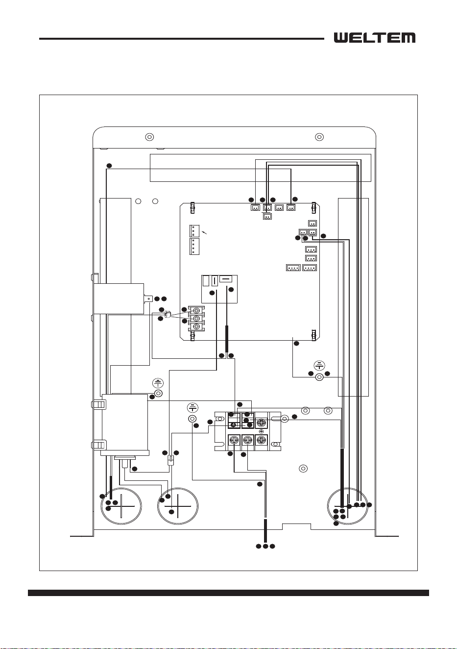
1
1
2
3
1 2 3
4
4
4
5
5
5
6
7
6 7
8
8
8
9
10
12
12
13
13
14
14
14
15
15
16 17
16 17
18
21 2223
24
24
25 26 27 28 29 30
Data
cable connector
FD FT
TH-2
TH-1
HP(PS)
TH-3
NC
N - 1A
L - 1A
NO
L N
COM
10
11
11
11
15
15
18
18
19
20
20
2223 21
24
Capacitor for
Motor
Capacitor for
Compressor
Electrical parts and relay board removal
WPC-3000P / 5000P
40 page
Service Manual
WPC-3000P / WPC-4000P / WPC-5000P
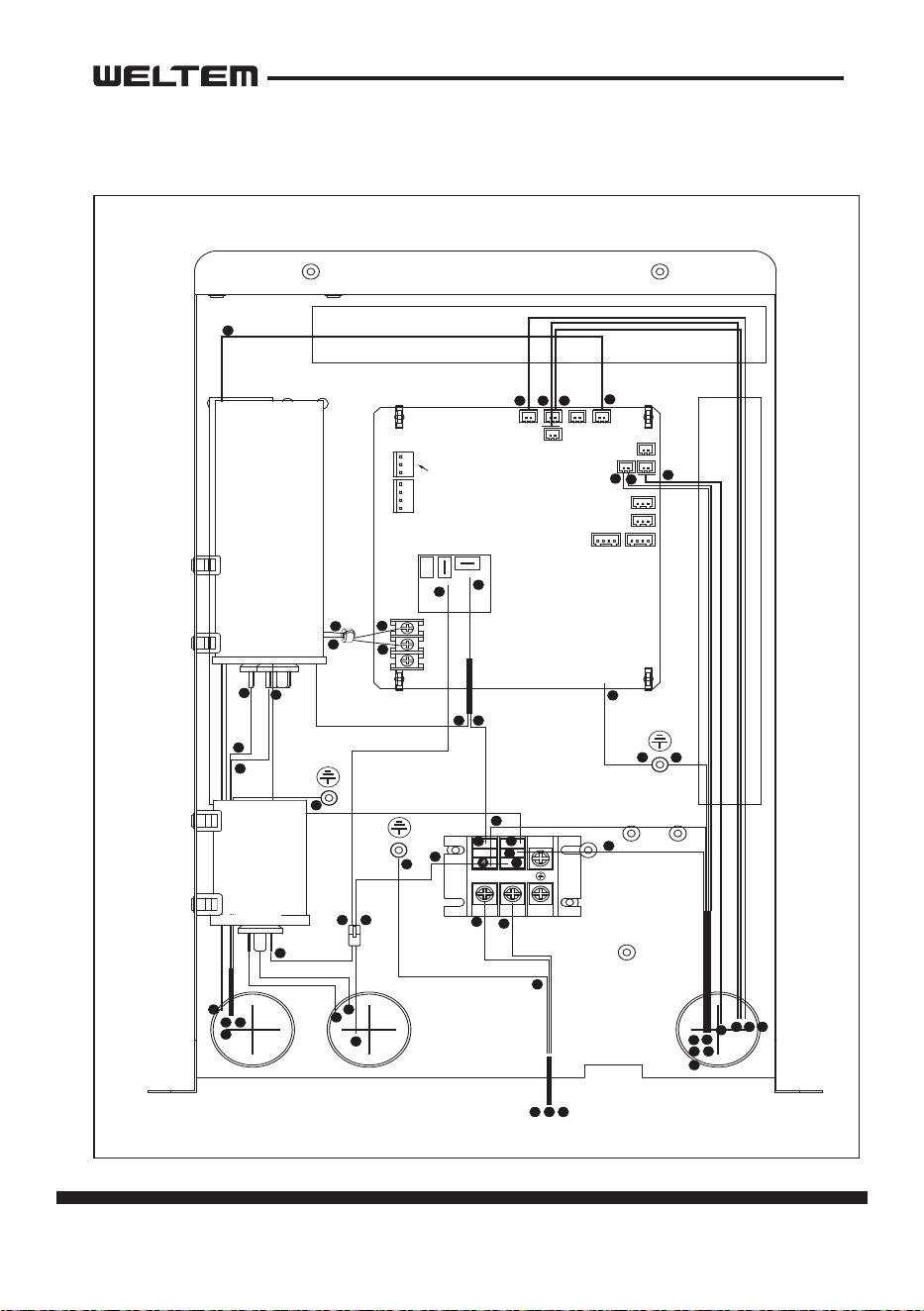
1
1
2
3
1 2 3
4
4
4
5
5
5
6
7
6 7
8
8
8
9
10
12
12
13
13
14
14
14
15
15
16
16
17
17
16 17
18
21 2223
24
24
Data
cable connector
FD FT
TH-2
TH-1
HP(PS)
TH-3
NC
N - 1A
L - 1A
NO
L N
COM
10
11
11
11
15
15
18
18
19
20
20
2223 21
24
Capacitor for
Compressor
25 26 27 28 29 30
Capacitor for
Motor
Electrical parts and relay board removal
WPC-4000P
page 41
Service Manual
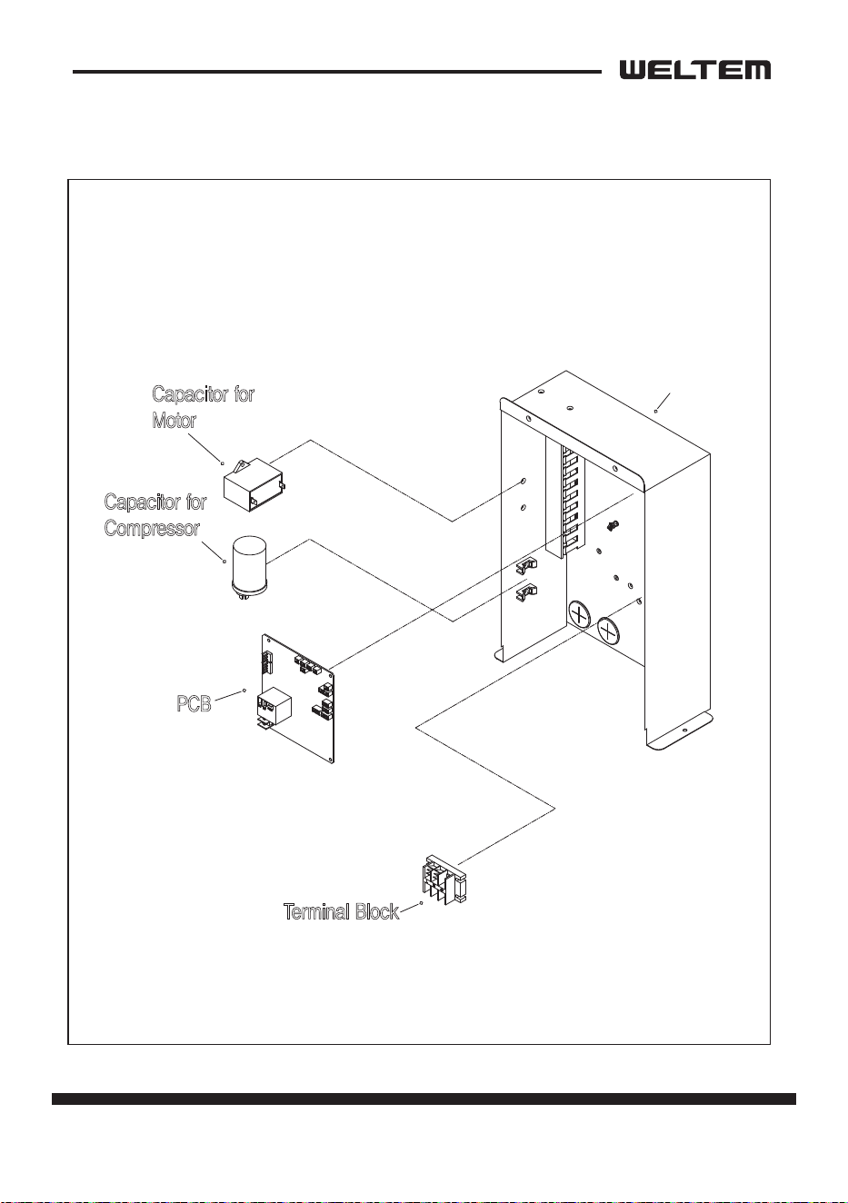
WPC-3000P / WPC-4000P / WPC-5000P
WPC-3000P/5000P
Control Box
PCB
Terminal Block
Capacitor for
Compressor
Capacitor for
Motor
42 page
Service Manual
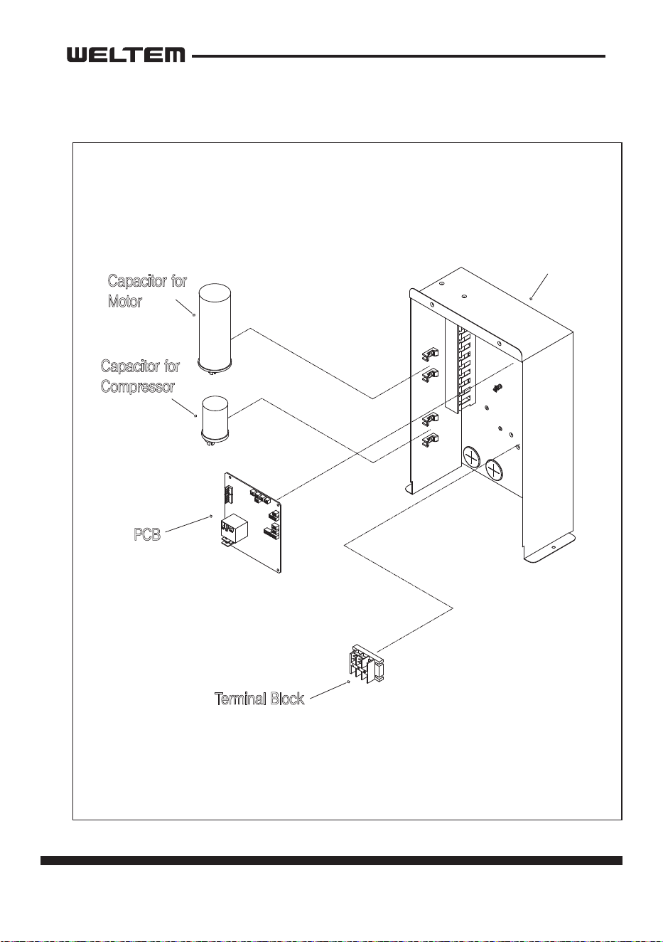
WPC-3000P / WPC-4000P / WPC-5000P
WPC-4000P
Control Box
PCB
Terminal Block
Capacitor for
Compressor
Capacitor for
Motor
page 43
Service Manual
WPC-3000P / WPC-4000P / WPC-5000P
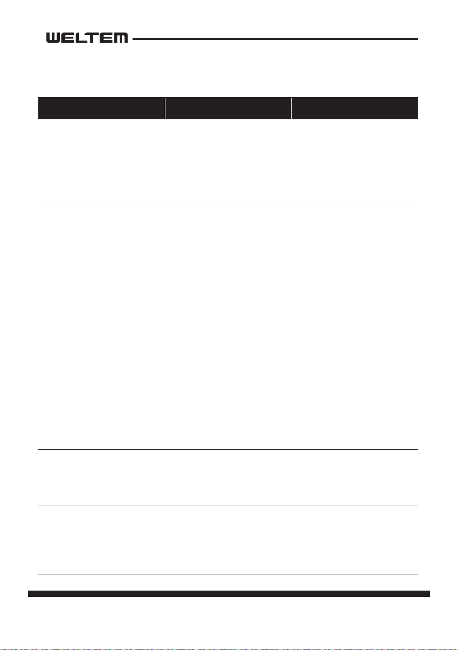
Fan Motor Removal
Eva Top Cover
5) Evaporator Fan
2) Condenser Fan
1) Bell mouse
6) Fan Motor
4) Motor Bracket
Paron Plate
Housing for Evaporator Fan
3) Housing for
Condenser Fan
1) Take o the four (4) bolts , and then remove the bell mouse.
2) Loosen the set screw with a hex key, and then remove the condenser fan.
3) Take o the three (3) nuts , and then remove the condenser fan housing.
4) Take o the four (4) nuts, and then remove the fan motor together with the
motor bracket.
5) Loosen the set screw with a hex key, and then remove the evaporator fan.
6) Take out the four (4) nuts, and then remove the fan motor.
44 page
Service Manual
WPC-3000P / WPC-4000P / WPC-5000P
REFRIGERANT SYSTEM REPAIR
Brazing
• In the event of a leak, obstrucon, or trouble in the refrigerant system of the unit,
replace or repair the defecve component. Aer replacing defecve component,
braze all connecons.
1) Proper brazing techniques
• When brazing, use a slightly reduced ame. Oxyacetylene is commonly used since
the ame condion can be easily judged and adjusted. Unlike gas welding, a sec
-
ondary ame is used for brazing. Properly preheat the base metal according to the
shape, size and thermal conducvity of the brazed ng.
• The most important point in ame brazing is to bring the enre brazed ng to
a proper brazing temperature. Care should be taken not to cause overow of the
brazing ller metal, oxidaon of the brazing ller metal, or ller metal deteriora
-
on due to overheang the ux.
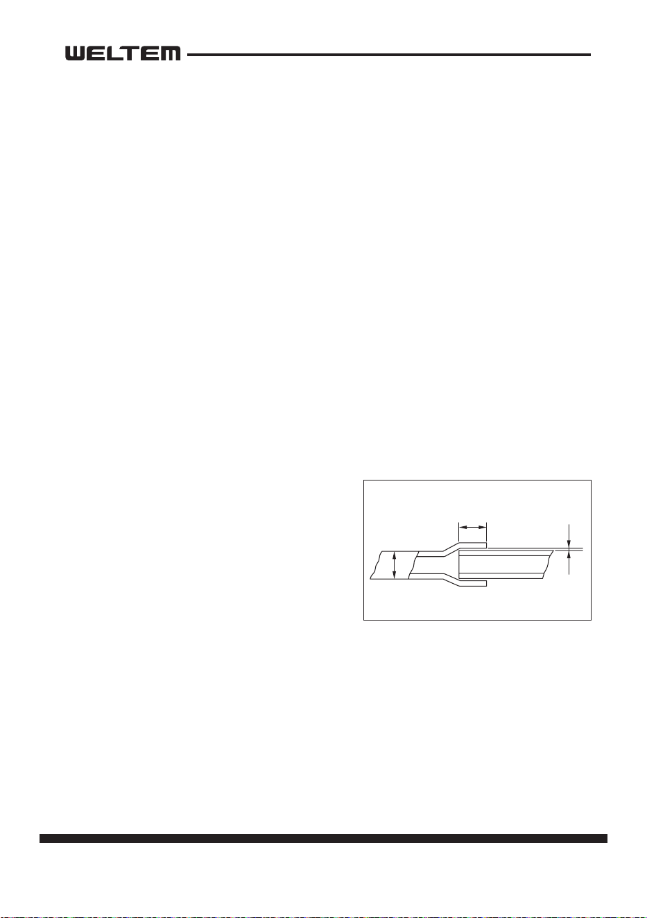
2) Brazed ngs and ng clearance
• In general, the strength of the brazing ller metal is lower than that of the base
metal. As such, the shape and clearance of
brazed ngs are very important. Concern
-
ing the shape of brazed ngs, adhesive
area must be maximized. In addion, the
clearance of the brazed ng must be mini
-
mized so that the brazing ller metal will
ow into the ng via capillary acon.
Clearance
Clearance From The Pipe Fing and Tubing.
0.001~0.003 in
(0.025~0.075 mm)
a
a
page 45
Service Manual
WPC-3000P / WPC-4000P / WPC-5000P
3) Cleaning brazing ller metal and piping
• When the refrigerant system has been opened, exposure to heat may cause the
brazing ller metal to sck to the inside and outside of the piping. Brazing ller
metal may also combine with oxygen in the air to form an oxide lm. In addion,
grease and oils may sck to the pipe during handling. All these factors will reduce
the eecveness of brazing. Therefore, excess brazing ller metal must be removed
with sand paper, and by thorough cleaning with a solvent such as Trichlene.
4) Dry Nitrogen gas use
• During brazing, the inside of the pipe undergoes an oxidave reacon due to the
brazing ame. Introduce dry nitrogen gas (0.3 gal/min (1 L/min); adjust with the
ow regulator) through the pinch-o tube of the refrigerant cycle to prevent oxi
-
daon.
NOTE:Do not get foreign maer such as dirt, water, or oil into the piping.
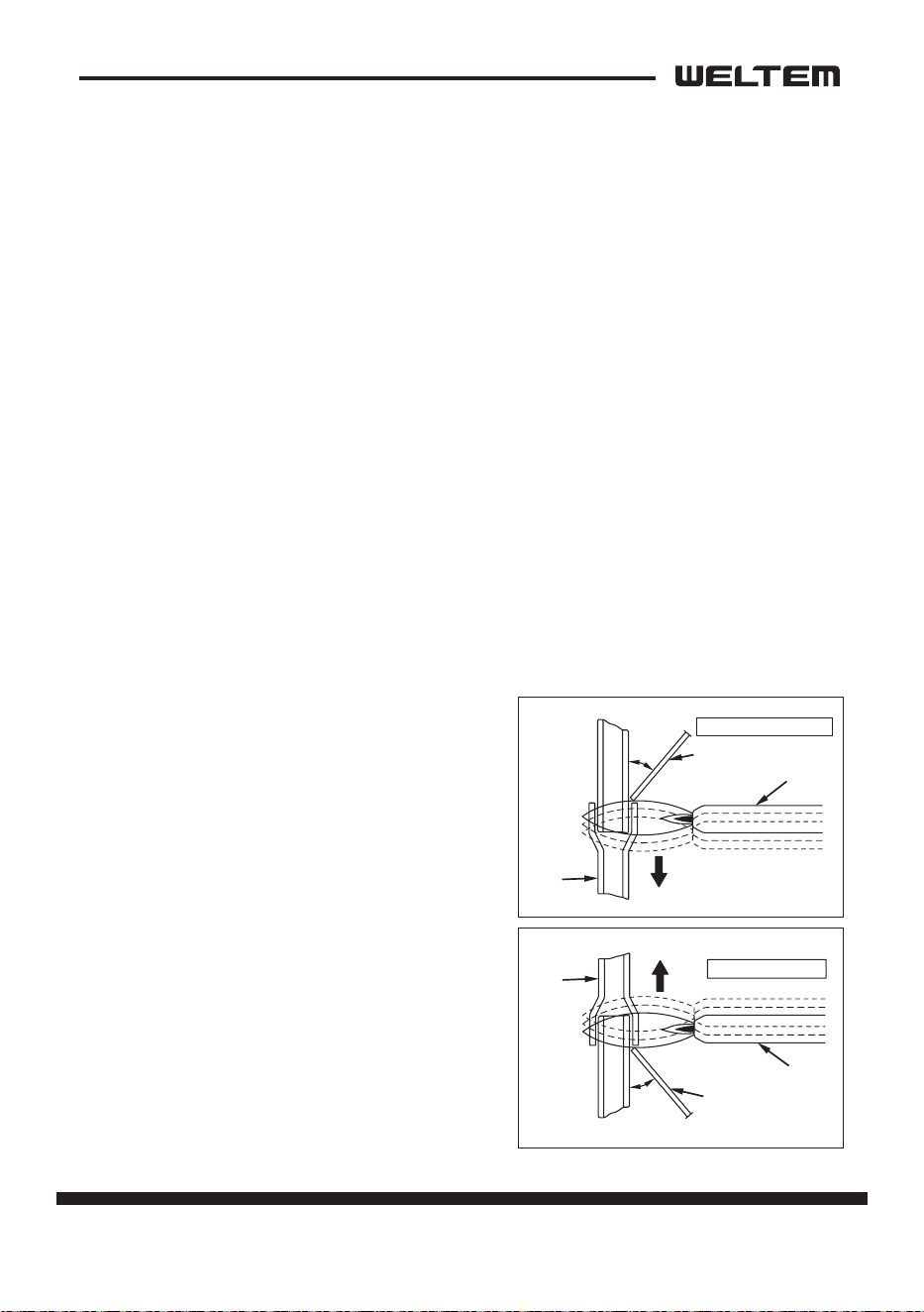
5) Vercal joints
• For vercal joints, heat the enre brazed ng to the proper brazing temperature.
Bring the brazing ller metal into contact with the ng so that the brazing ller
metal begins to ow.
• Stop heang the ng as soon as the braz
-
ing ller metal has own into the gap (clear-
ance). Since the brazing ller metal ows
easily into porons heated to the proper
temperature, the enre ng must be kept
at the proper brazing temperature.
Burner
45°
Tube
Brazing Filler Metal
Vercal Down Joint
Tube
Burner
45°
Brazing Filler Metal
Vercal Up Joint
46 page
Service Manual
WPC-3000P / WPC-4000P / WPC-5000P
WARNING
Charging the System with R-410A Refrigerant
• Always ensure that the refrigerant system has been properly evacuated before
charging with the specied amount of R-410A.
• Equipments is only for R-410A.
• Liquid charge (no gas charge).
• Make sure not to use more than 90 % of the inial weight of R-410A in the
cylinder.
• When handling refrigerant (R-410A), the following precauons should al
-
ways be observed:
- Always wear proper eye protecon while handling refrigerant.
- Maintain the temperature of the refrigerant container below 104 °F (40 °C).
- Perform repairs in a properly venlated area. (Never in an enclosed environ
-
ment.)
- Do not expose refrigerant to an open ame.
- Never smoke while performing repairs, especially when handling refrigerant.
- Be careful the liquid refrigerant does not come in contact with the skin.
• If liquid refrigerant strikes eye or skin:
- Do not rub the eye or the skin.
- Splash large quanes of cool water on the eye or the skin.
- Apply clean petroleum jelly to the skin.
- Go immediately to a physician or to a hospital for professional treatment
page 47
Service Manual
WPC-3000P / WPC-4000P / WPC-5000P
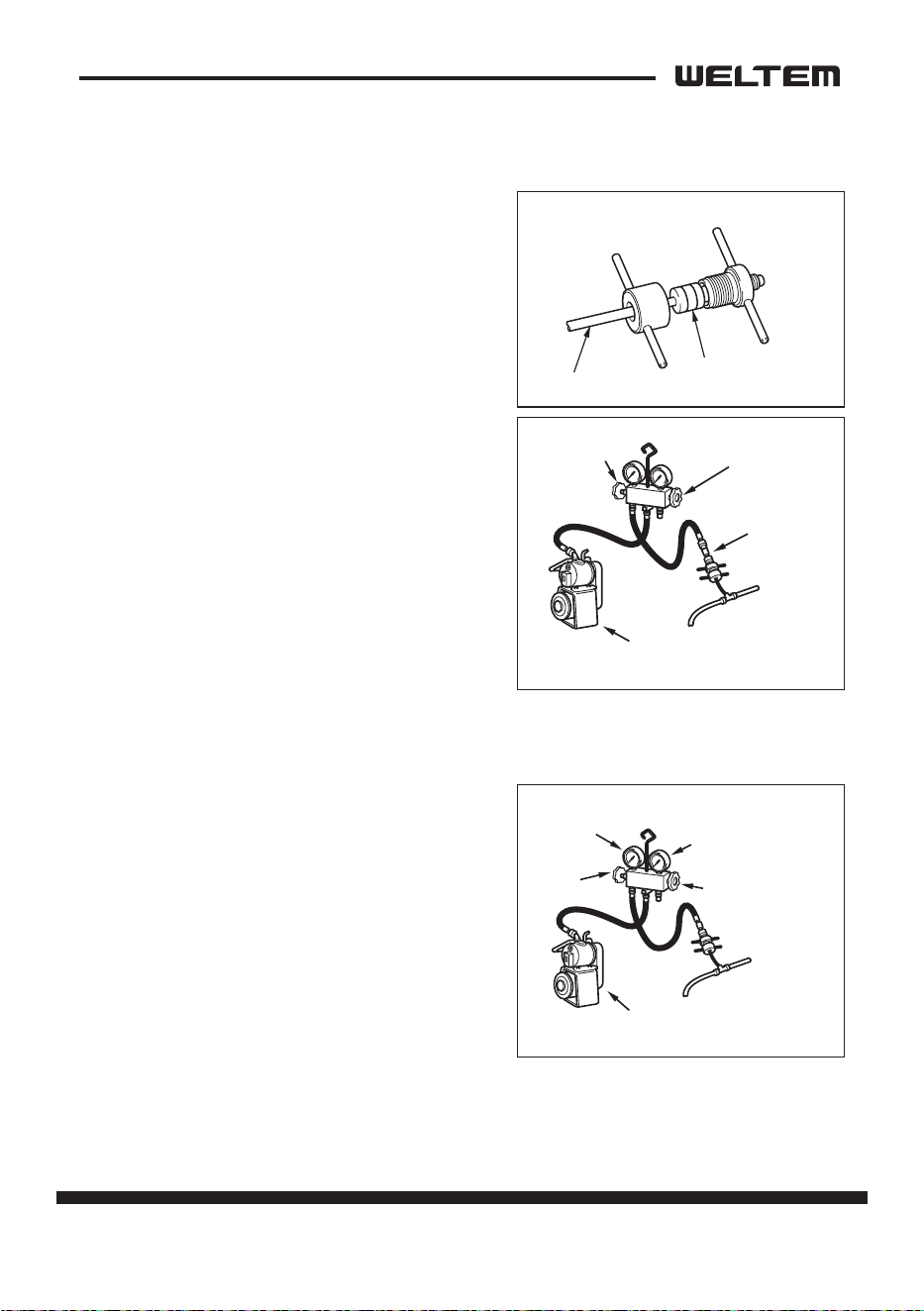
Connecon of gauge manifold
1) Properly remove the crushed end of the
pinch-o tube at the high pressure side and
the low pressure side of the refrigerant cycle
with a pipe cuer.
2) Fit the process tube ng to the pinch-o
tube on both sides.
3) Connect the charging hoses (low pressure
side) for the gauge manifold to the tube t
-
ng.
NOTE: Connect the hoses using care not to
mistake the high pressure side for the
low pressure side and vice versa.
4) Connect the charging hose at the center of
the gauge manifold to the vacuum pump.
Evacuaon
1) Open the low pressure valve (LOW) of the
gauge manifold.
2) Turn on the vacuum pump to start evacua
-
on.(Evacuate the system for approximate-
ly 30 min.)
3) When the low pressure gauge indicates 30
inHg(100 kPa), turn o the vacuum pump
and close the low pressure valves of the
gauge manifold.
4) Leave the high pressure valve and the low
-
pressure valve of the gauge manifold closed
for ve min or more, and conrm that the gauge pointer does not return to zero.
High Pressure Valv
e
(Closed)
Low Pressure
Side Tube
Vacuum Pump
(when stopped)
Low Pressure
Va
lve (Closed)
Tube Fitting
Pinch-Off Tube
Seal
Charging Hose
Side
Refrigerant
Cycle Side
Low Pressure
Side Tube
Vacuum Pump
(when stopped)
30 inHg (100 kPa) or larger
High Pressure Valv
e
High Pressure Gauge
Low Pressure Gauge
Low Pressure
Valv
e
48 page
Service Manual
WPC-3000P / WPC-4000P / WPC-5000P
Refrigerant Charging Work
(1)Refrigerant charging
1) Remove the charging hose from the vacuum
pump, and connect it to the refrigerant cyl
-
inder (R-410A).
2) Loosen the nut on the gauge manifold side
of the charging hose. Open the valve of the
charging hose. Open the valve of the refrig
-
erant cylinder. Aer air purging, ghten this
nut and close the valve of the refrigerant
cylinder.
3) Securely place the refrigerant cylinder on a
scale with a weighing capacity of 70 lb
(30 kg) that is graduated by 0.2 oz (5 g).
4) Open low the high pressure valve of the gauge manifold and the valve of the
refrigerant cylinder. Charge the system with refrigerant to the specied amount.
Standard Amount of Refrigerant:
- WPC-3000P: 21.1oz (570g)
- WPC-4000P: 19.4oz (550g)
- WPC-5000P: 25oz (710g)
5) Close the high pressure valve of the gauge manifold and the valve of the refriger
-
ant cylinder.
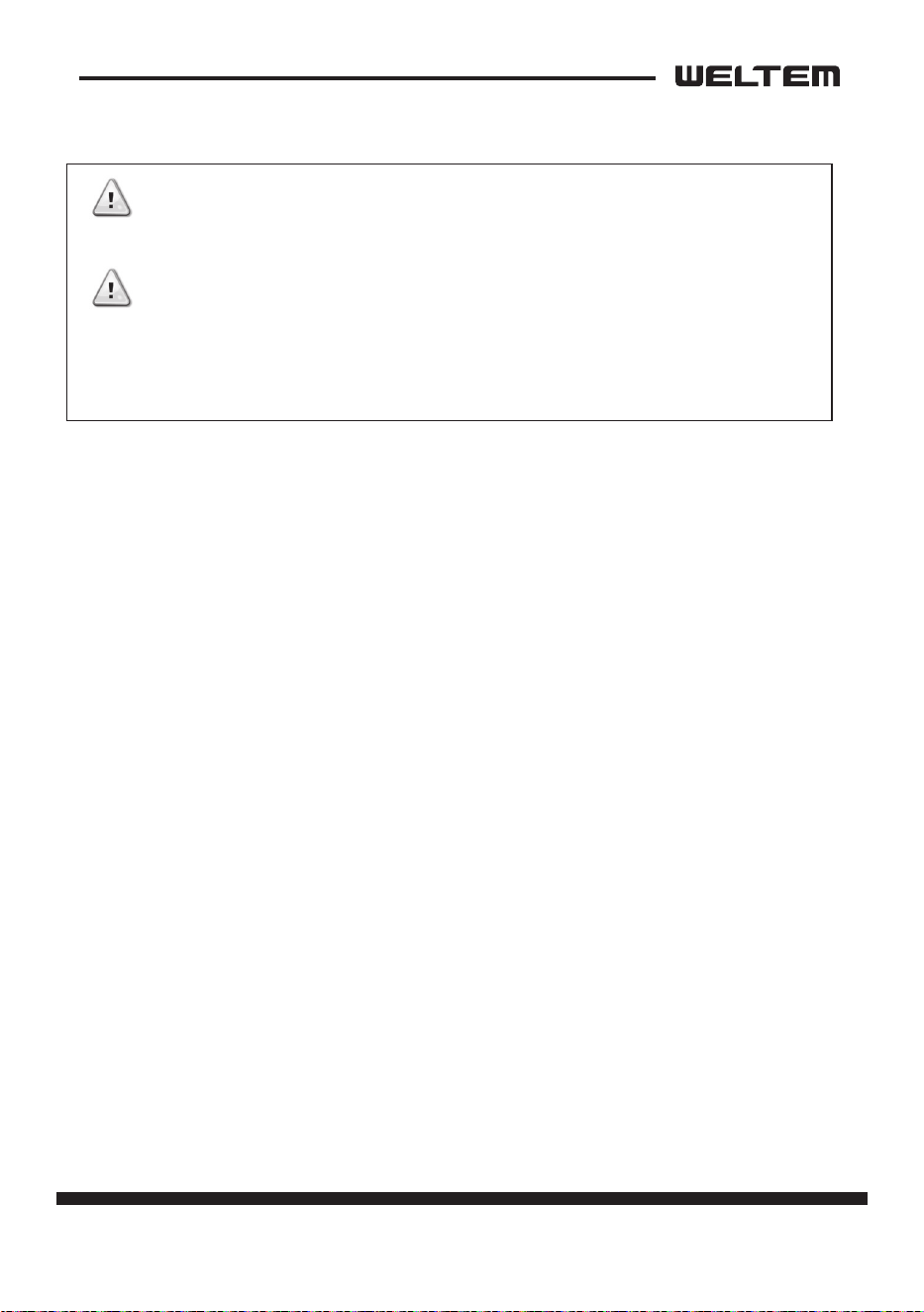
(2)Removal of gauge manifold
1) Crimp the pinch-o tube with a pinch-o
tool.
2) Remove the gauge manifold and the pro
-
cess tube ng. Crush the end of the
pinch-o tube.
3) Braze the end of the pinch-o tube.
4) Ensure that a gas leak is not present at the
pinched o poron and the brazed end.
CAUTION
The amount of refrigerant charged has a great eect on
the cooling capacity of the unit. Charge to the specied
amount,always observing the scale graduaons while
charging.
Refrigerant
Cylinder R-410A
Low Pressure
Side Tube
Low Pressure Valve
Valve of
Refrigerant
Cylinder
LO
Closed
HI
Open
LO
Closed
HI
Closed
Valve Setting
Specified Amount
of Refrigerant
Pinch-Of
f Tube
Pinch-Off Tool
Process Tube Fitting
Charging Hose
To Gauge
Manifold Side
To Refrigerant
Cycle Side
page 49
Service Manual
WPC-3000P / WPC-4000P / WPC-5000P
•Do not aempt any repair on a charged system.
• Before checking for gas leaks, fully conrm that there is nothing ammable in
the area to cause an explosion or re. Contact of refrigerant with an open re
generates toxic gas.
WARNING
WARNING

154, Jayumuyeok 3-gil, Masanhoewon-gu, Changwon-City, Gyeongsangnam-do, 51340 Korea
TEL: +82-55-294-9200(ext.2) FAX: +82-55-294-9220 http://www.weltem.com