Installation Guide &
Instruction Manual
IMPORTANT:
Read and save these instruc
tions
NO
TICE:
Installer: Leave this guide with the homeowner
Homeowner: Keep this guide for future reference
WALL MOUNT RANGE HOOD
10/2023
Thank you for purchasing a
FORNO
product. Please read the entire instruction manual before operating
your new appliance for the first time. Whether you are an occasional user or an expert , it will be beneficial
to familiarize yourself with the safety practices, features, operation and care recommendations of your
appliance.
Both the model and serial number are listed inside the product. For warranty purposes, you will also need
the serial number, the date of purchase & a copy of your proof of purchase.
Record
this
information
below
for future
reference.
Use these number in any correspondance or
service calls concerning your product.
If you received a damaged product,
immediately contact FORNO.
Save time and money. Before you call for
service, check the Troubleshooting Guide. It
lists the causes of minor operating problems
that you can correct yourself.
SERVICE IN CANADA & UNITED STATES
Keep the instruction manual handy to answer your questions. You can also find all the information
you need online at www.forno.ca.
If you don't understand something or need more assistance, please visit our website or email:
info@forno.ca
If there is a problem, please contact FORNO customer service. Please note that troubleshooting
with a customer service representative will be needed before being able to send a service provider.
All warranty work needs to be authorized by FORNO customer service. All our authorized
service providers are carefully selected and rigorously trained by us.
3

Warranty
What this limited warranty covers:
The Warranty coverage provided by Forno Appliances in this statement applies exclusively to the original Forno
appliance (“Product”) sold to the consumer (“Purchaser”) by an authorized Forno dealer/distributor/retailer,
purchased and installed in the United States or Canada, and which has always remained within the original country
of purchase (the United States or Canada). Warranty coverage is activated on the date of the Product's original
retail purchase and has a duration of two (2) years.
Warranty coverage is non-transferable. In the event of replacement of parts or of the entire product, the
replacement Product (or parts) shall assume the remaining original Warranty activated with the original retail
purchase document. This Warranty shall not be extended with respect to such replacement. Forno Appliances will
repair or replace any component/part which fails or proves defective due to materials and/or workmanship within
2 years of the date of the original retail purchase and under conditions of ordinary residential, non-
commercial use. Repair or replacement will be free of charge, including labor at standard rates and shipping
expenses. Purchaser is responsible for making the Product reasonably accessible for service. Repair service must
be performed by a Forno Authorized Service company during normal working hours.
IMPORTANT
Retain proof of original purchase to establish warranty period. Forno’s liability on any claim of any kind, with
respect to the goods and/or services provided, shall in no event exceed the value of the goods or service or part
there of which has given rise to the claim.
30-Day Cosmetic Warranty
The Purchaser must inspect the product at the time of delivery. Forno warrants that the Product is free from
manufacturing defects in materials and workmanship for a period of thirty (30) days from date of the original reta
il
pur
chase of the Product.
This coverage includes:
- Paint blemishes
- C
hips
-
Macroscopic finish defects
Cosmetic warranty does NOT cover:
> issues resulting from incorrect transport, handling and/or installation (e.g.: dents, broken, warped or deformed
s
tructures or components, cracked or otherwise damaged glass components);
> s
light color variations on painted/enameled components;
> d
ifferences caused by natural or artificial lighting, location or other analogous factors;
>
stains/corrosion/discoloration caused by external substances and/or environmental factors;
> labor costs, display, floor, B-stock, out- of-box,“as is” appliances and demo units.
How to receive service
To receive warranty services, the Purchaser must contact the Forno Support department in order to determine
the problem and the required service procedures. Troubleshooting with a customer service representative will be
necessary before moving forward with the service. Model number, serial number and date of original retail
purchase will be requested.
4

Warranty Exclusions: What Is Not Covered.
> Use of the Product in any non-residential,
commercial application.
> U
se of the Product for anything other than its
intended purpose.
> R
epair services provided by anyone other than a
F
orno Authorized Service agency.
> D
amages or repair services to correct services
provided by unauthorized parties or the use of
unauthorized parts.
> I
nstallation not in accordance with
local/state/city/county fire codes, electrical codes, gas
codes, plumbing codes, building codes, laws or
regulations.
> Defects or damage due to improper storage of the
Pr
oduct.
> D
efects,damage or missing parts on products sold
out
of the original factory packaging or from displays.
> S
ervice calls or repairs to correct an incorrect
installation of the Product and/or related accessories.
> R
eplacement of parts/service calls to connect,
convert or otherwise repair the electrical wiring and/or
gas line in order to properly use the product.
> R
eplacement of parts/service calls to provide
instructions and information on the use of the Product.
> R
eplacement of parts/service calls to correct issues
arising from the product being used in a manner other
than what is normal and customary for residential use.
> R
eplacement of parts/service calls due to wear and
tear of components such as seals, knobs, pan
supports, shelving, cutlery baskets, buttons, touc
h
d
isplays, scratched or broken ceramic-glass tops.
> Replacement of parts/service calls for lack
of/improper maintenance, including but not limited to:
build up of residues, stains, scratches, discoloration
,
c
orrosion.
> D
efects and damages arising from accidents,
alteration, misuse, abuse or improper installation.
> D
efects and damages arising from Product
transport, logistics and handling. Inspection of the
product must be made at time of delivery. Followi
ng
r
eceipt and inspection, the selling dealer/delivery
company must be notified of any issues arising from
handling, transport and logistics.
> D
efects and damages arising from external forces
beyond the control of Forno Appliances, including but
not limited to wind, rain, sand, fires, floods, mudslides,
freezing temperatures, excessive moisture or extended
exposure to humidity, power surges, lightning,
structural failures surrounding the appliance and other
acts of God.
> Pr
oducts whose serial number has been
altered/damaged/tampered with. In no case shall Forno
be held liable or responsible for damage to surrounding
property, including furniture, cabinetry, flooring, panels,
and other structures surrounding the Product. Forno is
ne
ither liable nor responsible for the Product if it is
located in a remote area or an area where certifi
ed
t
rained technicians are not reasonably available.
Purchaser must bear any transportation and delivery
costs of the Product to the nearest Authorized Service
C
enter or the additional travel expenses of a certifi
ed
t
rained technician
THERE ARE NO EXPRESS WARRANTIES OTHER THAN THOSE LISTED AND DESCRIBED ABOVE, AND NO
WARRANTIES, EITHER EXPRESS OR IMPLIED, INCLUDING, BUT NOT LIMITED TO, ANY IMPLIED
WARRANTIES OF MERCHANTABILITY OR FITNESS FOR A PARTICULAR PURPOSE THAT SHALL APPLY
AFTER THE EXPRESS WARRANTY PERIODS STATED ABOVE, AND NO OTHER EXPRESS WARRANTY OR
GUARANTEE GIVEN BY ANY PERSON, FIRM OR CORPORATION WITH RESPECT TO THIS PRODUCT SHALL
BE BINDING ON FORNO. FORNO SHALL NOT BE LIABLE FOR LOSS OF REVENUE OR PROFITS, FAILURE
TO REALIZE SAVINGS OR OTHER BENEFITS, TIME AWAY FROM WORK, MEALS, LOSS OF FOOD OR
BEVERAGES, TRAVELING OR HOTEL EXPENSES, EXPENSES TO RENT OR PURCHASE APPLIANCES,
REMODELING/CONSTRUCTION EXPENSES IN EXCESS OF DIRECT DAMAGES WHICH ARE UNDENIABLY
CAUSED EXCLUSIVELY BY FORNO OR ANY OTHER SPECIAL, INCIDENTAL OR CONSEQUENTIAL
DAMAGES CAUSED BY THE USE, MISUSE OR INABILITY TO USE THIS PRODUCT, REGARDLESS OF THE
LEGAL THEORY ON WHICH THE CLAIM IS BASED, AND EVEN IF FORNO HAS BEEN ADVISED OF THE
POSSIBILITY OF SUCH DAMAGES. NOR SHALL RECOVERY OF ANY KIND AGAINST FORNO BE GREATER
IN AMOUNT THAN THE PURCHASE PRICE OF THE PRODUCT SOLD BY FORNO AND CAUSING THE
ALLEGED DAMAGE.WITHOUT PREJUDICE TO THE FOREGOING, PURCHASER ASSUMES ALL RISK AND
LIABILITY FOR LOSS, DAMAGE OR INJURY TO PURCHASER AND PURCHASER’S PROPERTY AND TO
OTHERS AND THEIR PROPERTY ARISING FROM THE USE, MISUSE, OR INABILITY TO USE THIS PRODUCT
SOLD BY FORNO THAT IS NOT A DIRECT RESULT OF NEGLIGENCE ON THE PART OF FORNO THIS LIMITED
WARRANTY SHALL NOT EXTEND TO ANYONE OTHER THAN THE ORIGINAL PURCHASER OF THIS
PRODUCT, IS NON-TRANSFERABLE, AND STATES YOUR EXCLUSIVE REMEDY.
5
SAFETY INSTRUCTIONS
This is the safety alert symbols. These symbols alert you to potential hazards
that can hurt you and others. All safety messages will follow the safety alert
symbols.
READ ALL INSTRUCTIONS BEFORE INSTALLING AND OPERATING THIS APPLIANCE.
• The installation instructions in this manual are intended for qualified installers, service technicians,
or persons with similar qualified background. Installation and electrical wiring must be done by
qualified professionals and in accordance with all applicable codes and standards, including
first-rated construction. DO NOT attempt to install this appliance yourself. Injury could result from
installing the unit due to lack of appropriate electrical and technical background. Due to the siz
e
a
nd weight of this range hood, two people installation is recommended.
• Range hood may have very sharp edges; please wear protective gloves if it is necessary to
remove any parts for installing, cleaning, or servicing.
• Activating any switch ON before completing installation may cause ignition or an explosion.
TO REDUCE THE RISK OF FIRE, ELECTRIC SHOCK OR INJURE TO PERSONS, PLEASE
OBSERVE THE FOLLOWINGS:
• Your safety and the safety of others is very important. We have provided many important safety
messages in this manual and on your appliance. Always read and obey all safety messages. All
safety messages will tell you what the potential hazard is, tell you how to reduce the chance of
injury, and tell you what can happen if the instructions are not followed.
• All electrical wiring must be properly installed, insulated, and grounded.
• Old duct work should be cleaned or replaced, if necessary, to avoid the possibility of a grease fire.
Check all joints on duct work to insure proper connection, all joints should be properly taped.
• When the range hood ventilates the air out of the room, the air vented must be replaced, this is
called make-up air. If a makeup air system is needed, but not used, a hood may not function as
expected due to negative air pressure. We do not currently provide a make-up air unit. Always
consult any applicable building codes in your area regarding minimum and maximum air flow
rates. Certain states may require additional items such as make-up air for larger CFM range
hoods (typically over 300 CFM).
• To reduce the risk of fire and to disperse air properly, make sure to vent air outside. DO NOT vent
exhaust into spaces between walls, crawl spaces, ceilings, attics, or garages.
• For residential ventilating use only. DO NOT use to exhaust hazardous or explosive materials and
vapors. The combustion air flow needed for safe operation of fuel-burning equipment may be
affected by this unit’s operation. Follow the heating equipment manufacturer’s guideline and

safety standards such as those published by the National Fire Protection Association (NFPA), and
the American Society of Heating, Refrigeration and Air Conditioning Engineers (ASHRAE), and
the local code authorities. Sufficient air is needed for proper combustion and exhausting of gases
through the duct to prevent back drafting.
• Ducted range hoods MUST ALWAYS be vented to the outdoors. All our range hoods come with a
transition piece with a built-in damper. Some existing installations may already have an external
d
amper. Please consult an HVAC or installation professional for advice to comply with loca
l
regulat
ions.
• Keep all fans, baffle, spaces, filter, grease tunnel, oil container and grease-laden surfaces clean.
Grease should not be allowed to accumulate on fan, baffle, spaces, filter, grease tunnel or oil
container. Clean grease-laden surfaces frequently.
• This appliance is design to be operated by adults. Children were not allowed to temper with the
controls or play with this appliance.
• To reduce the risk of fire or electric shock, do not use this fan with any solid-state speed control
device.
• When cutting or drilling into wall or ceiling, do not damage electrical wiring and other hidden
utilities.
• Before servicing or cleaning unit, switch power OFF at service panel and lock service panel t
o
p
revent power from being switched ON accidentally.
• Use this unit only in the manner intended by the manufacturer. If you have any questions, contact
the FORNO.
TO REDUCE THE RISK OF INJURY TO PERSONS IN THE EVENT OF A STOVE TOP GREASE
FIRE:
• All FORNO range hoods are ETL listed, ensuring all parts were tested for safety and meet
industry standards and regulations. NOTE: This ensures all included metal ducting pieces wer
e
t
ested for safety and are flame retardant.
• Always turn hood ON when cooking at high heat or when cooking flaming foods (Crepes Suzette
,
C
herries Jubilee, Peppercorn Beef Flambe). Never leave surface units unattended at high
settings. Boil overs cause smoking and greasy spillovers that may ignite. Heat oils slowly on low
or medium settings.
• Clean hood frequently. Grease should not be allowed to accumulate on fan or filter.
• Use proper pan size. Always use cookware appropriate for the size of the surface element.

INSTALLATION & USE
NOTE 1: On stainless steel hoods, carefully remove the plastic protective film (if have) from all exterior
surfaces of the hood and chimney prior to final installation
NOTE 2: At least two people will be required to mount the hood.
DESCRIPTION / CO
NNECTION
This range hood should be mounted directly to the support frame mounting, where the support frame
flue shall secure to the ceiling joist or framework.
• Ductwork needs to be installed at the top of the unit where the motor(s) exhaust.
• Duct runs should be as short as possible.
• Avoid the use of elbows.
• Use duct tape at all joints.
• Do not use duct smaller than the discharge on the hood.
Electrical Connection
• Electrical wiring must be done by a qualified person(s) in accordance with all applicable codes
and standards. Turn off electrical power at service entrance before wiring.
• If the supply cord is damaged, it must be replaced by the manufacturer, its service agent, or
similarly qualified persons to avoid a hazard.
• Do not use the plug and an extension cord other than the ones initially supplied with the hood.
• The earthing of this hood is compulsory. Do not remove ground prong of the plug.
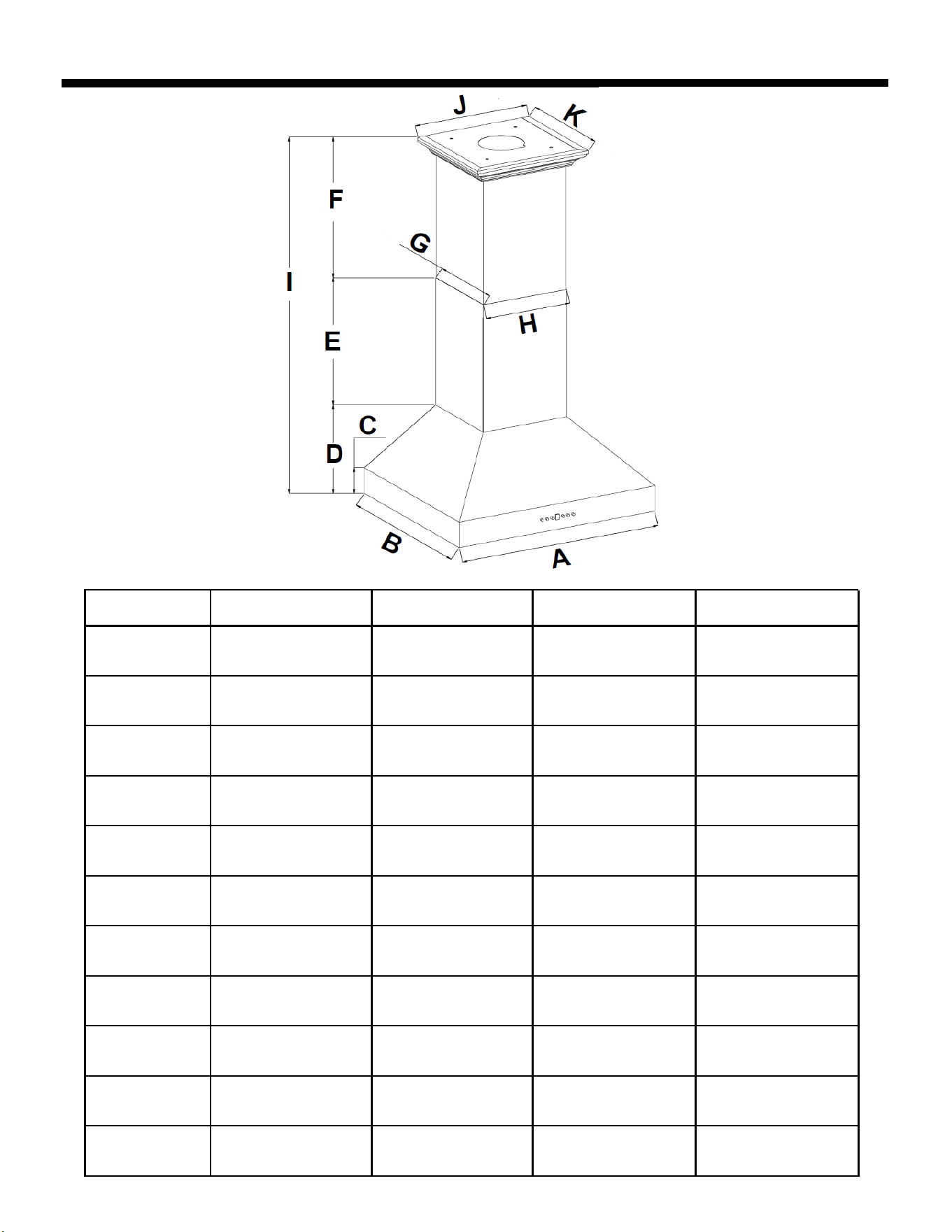
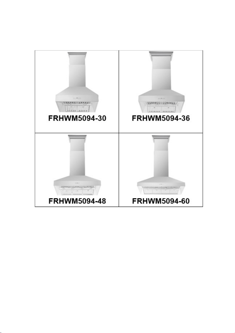
FRHWM5094-30 FRHWM5094-36 FRHWM5094-48 FRHWM5094-60
A
29
17
/
32
''
750mm
35
7
/
16
''
900mm
47
1
/
4
''
1200mm
59
1
/
16
''
1500mm
B
23
5
/
8
''
600mm 600mm 600mm 600mm
C
3
15
/
16
''
100mm 100mm 100mm 100mm
D
14
3
/
16
''
360mm 360mm 360mm 360mm
E
15
5
/
8
''
397mm 397mm 397mm 397mm
F
15
5
/
32
''
385mm
15
5
/
32
''
385mm
15
5
/
32
''
385mm
15
5
/
32
''
385mm
G
11
11
/
16
''
297mm
11
11
/
16
''
297mm
11
11
/
16
''
297mm
11
11
/
16
''
297mm
H
322mm
16
23
/
32
''
425mm 425mm 425mm
I
44
31
/
32
''
1142mm 1142mm 1142mm 1142mm
J
17
17
/
32
''
445mm
21
21
/
32
''
550mm 550mm 550mm
K
14
3
/
32
''
358mm 358mm 358mm 358mm
23
5
/
8
''
23
5
/
8
''
23
5
/
8
''
3
15
/
16
''
3
15
/
16
''
3
15
/
16
''
14
3
/
16
''
14
3
/
16
''
14
3
/
16
''
15
5
/
8
''
15
5
/
8
''
15
5
/
8
''
12
11
/
16
''
44
31
/
32
''
44
31
/
32
''
44
31
/
32
''
14
3
/
32
'' 14
3
/
32
''
14
3
/
32
''
21
21
/
32
'' 21
21
/
32
''
16
23
/
32
'' 16
23
/
32
''
OVERALL DIMENSIONS - VIEW FROM THE FRONT
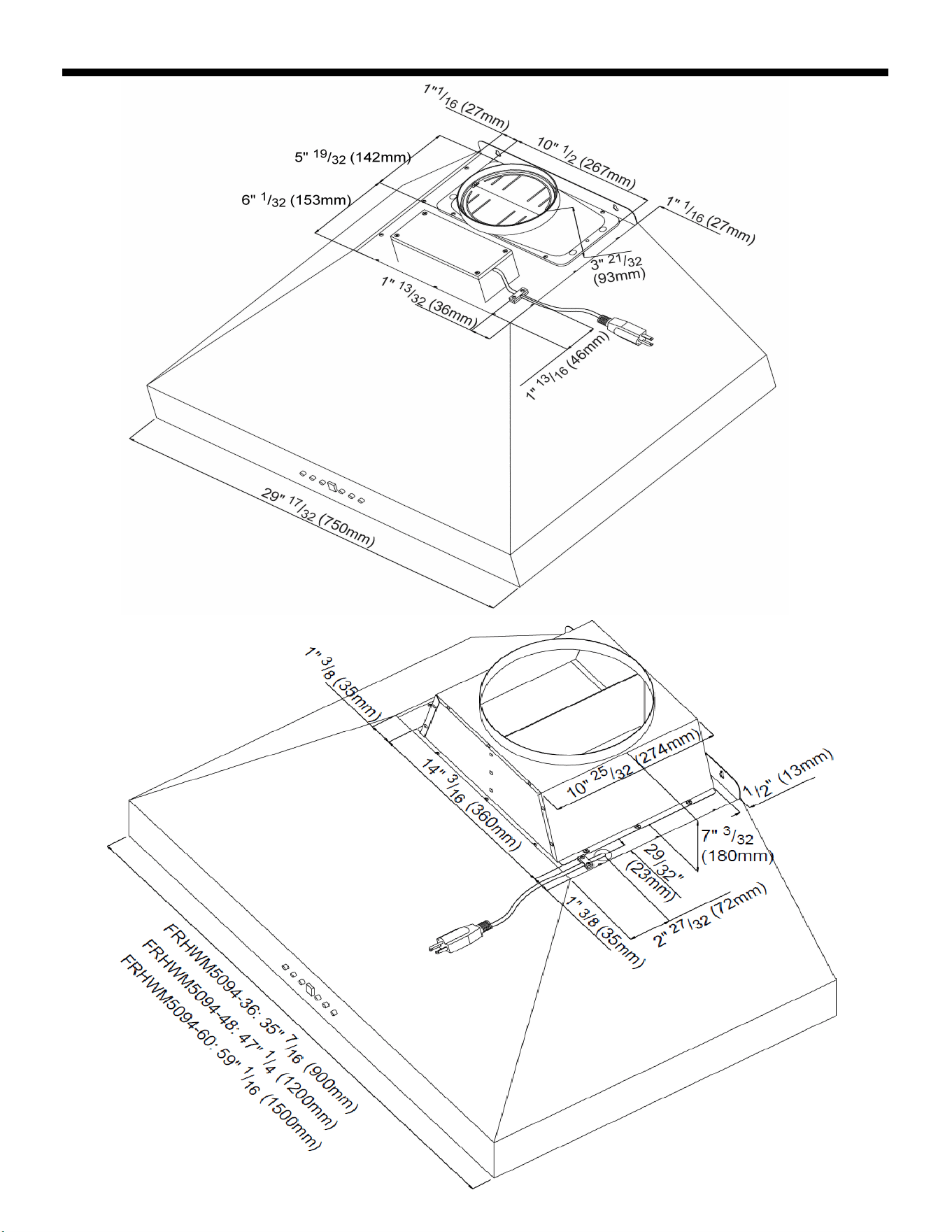
OVERALL DIMENSIONS - VIEW FROM THE 723(;+$86732:(5&25'/2&$7,21
)5+:0
FRHWM5094-36, FRHWM5094-48 & FRHWM5094-60
INSTALLATION PREPARATION
• Please plug in and check that all functions are working
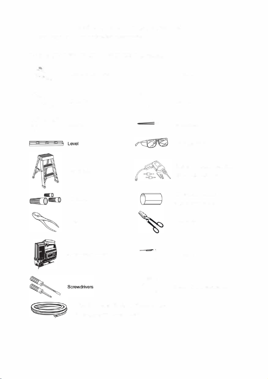
TOOLS AND MATERIALS REQUIRED (Not supplied)
�
Pencil and tape measure
�
Wire cutter/stripper
�
Hammer
Step ladder
Wire nuts
Pliers
Saber saw or Sawzall
@ Duct tape
�
Wrench
�
Keyhole Saw
Safety glasses
Electric or batte-operated
drill and 1/8", 3/8" bits
10" round metal duct,
length to suit installation
Metal Snips
c�_(]�D Flashlight
Strain relief for joint cover.
120V 60Hz. 15 or 20 Amp, 2-wire with ground.
Properly grounded branch circuit.
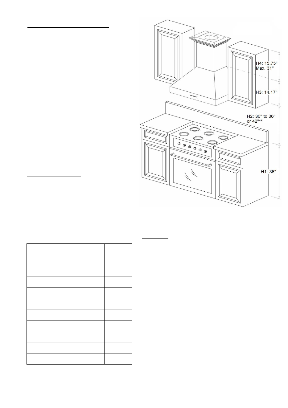
MOUNT HEIGHTS & CLEARANCE
The minimum mounting height between range
top to hood bottom should be no less than 30”.
The maximum height should be 36" above the
c
ooktop (**please note that the 36”, 48” &
60”
unit can install up to 42" above the
cooktop, but it may result in a loss of
efficiency)
It is important to install the hood at the
proper mounting height. Hoods mounted too
low could result in heat damage and fire
hazard; while hoods mounted too high will
be hard to reach and will lose its performance
and
efficiency.
Ducting (not provided)
NEVER exhaust air or terminate duct work into
spaces between walls, crawl spaces, ceiling,
attics, or garages. All exhaust must be ducted to
the outside. Use Metal ductwork only. Fasten all connections with sheet metal screws and tape all
joints w/ certified Silver Tape or Duct Tape.
Duct Run Calculation:
Maximum run 6” or 3-1/4 x 10”
duct
100FT
Deduct:
each 90 Elbow used 15FT
each 45 Elbow used 9FT
each 6” to 3-1/4 x 10” 1FT
transition used
each 3-1/4 x 10” to 6” 5FT
transition used
Side Wall Cap w/ damper 30FT
Roof Cap 30FT
e.g. – 1 roof cap, 2x90 elbows, 1x45 elbow = 30’ +
30’ + 9’=69’ used, 31’ available for straight duct runs
DUCT
SIZE
A minimum of φ 6” for 30” & 10’’ for 36”, 48’’ and 60’’
round duct must be used to maintain maximum
airflow efficiency.
Flexible ducts are provided for convenience, always
use rigid type metal ducts to maximize airflow.
Also use calculation (on left) to compute total
available duct run when using elbows, transitions,
and caps.
ALWAYS, reduce the number of transitions and
turns. If required a long duct increase duct size from
6” to 8” for the 30” & from 10” to 12” for the 36”, 48”
and 60”.
If a reducer is used, install a long reducer instead of
pancake reducer. Reduce duct size as far away
from opening as possible.
If turns or transitions are required: Install as far away
from opening and as far apart, between 2, as
possible
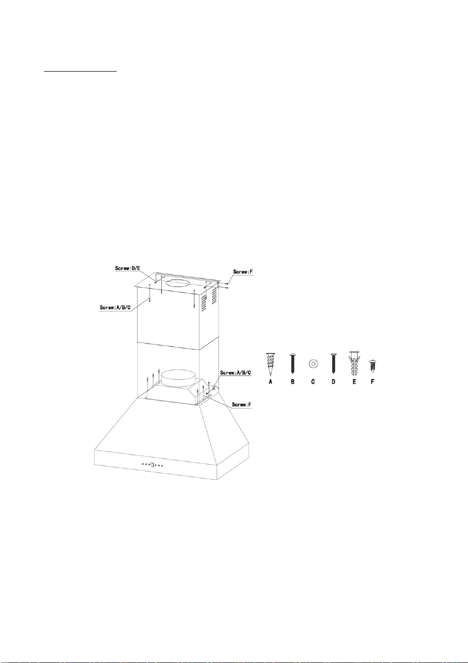
PREPARE LOCATION
Please unpack your range hood when it is delivered and inspect to ensure all parts are included.
1.
Hood body with Lights and Button
Pre-Installed
2.
Adjustable Stainless-Steel Chimney
Cover (2x,400mm high)
3.
Air Outlet Adapter (φ 6” for 30” & 10’’
for 36’’,48’’ and 60’’)
4. Duct (1.5m long, φ 6’’ for 30’’, φ 10’’
for 36’’,48’’ and 60’’)
5.
Baffle filters (4x for 30’’,36’’.6x for
48’’,8x for 60’’)
6.
Screws and Anchors
7.
Chimney Mounting Bracket
8.
Grease Cup
9.
Decorative Frame Bracket
10.
Decorative Frame
11.
Instruction Manual
N
OTE: Air Outlet Adapter on the FRHWM5094-30 is pre-installed on the unit.
• Lay out the vent duct system before installing the range hood to determine the best routing for the
vent duct.
• It is recommended that the vent system be installed before the range hood is installed.
• Before making cutouts, make sure there is proper clearance within the ceiling for exhaust vent.
• Range hood is to be installed 30" min. from cooking surfaces.
• Check your ceiling height and the range hood height maximum before you install your hood.
• At least two p
eople will be required to mount the hood
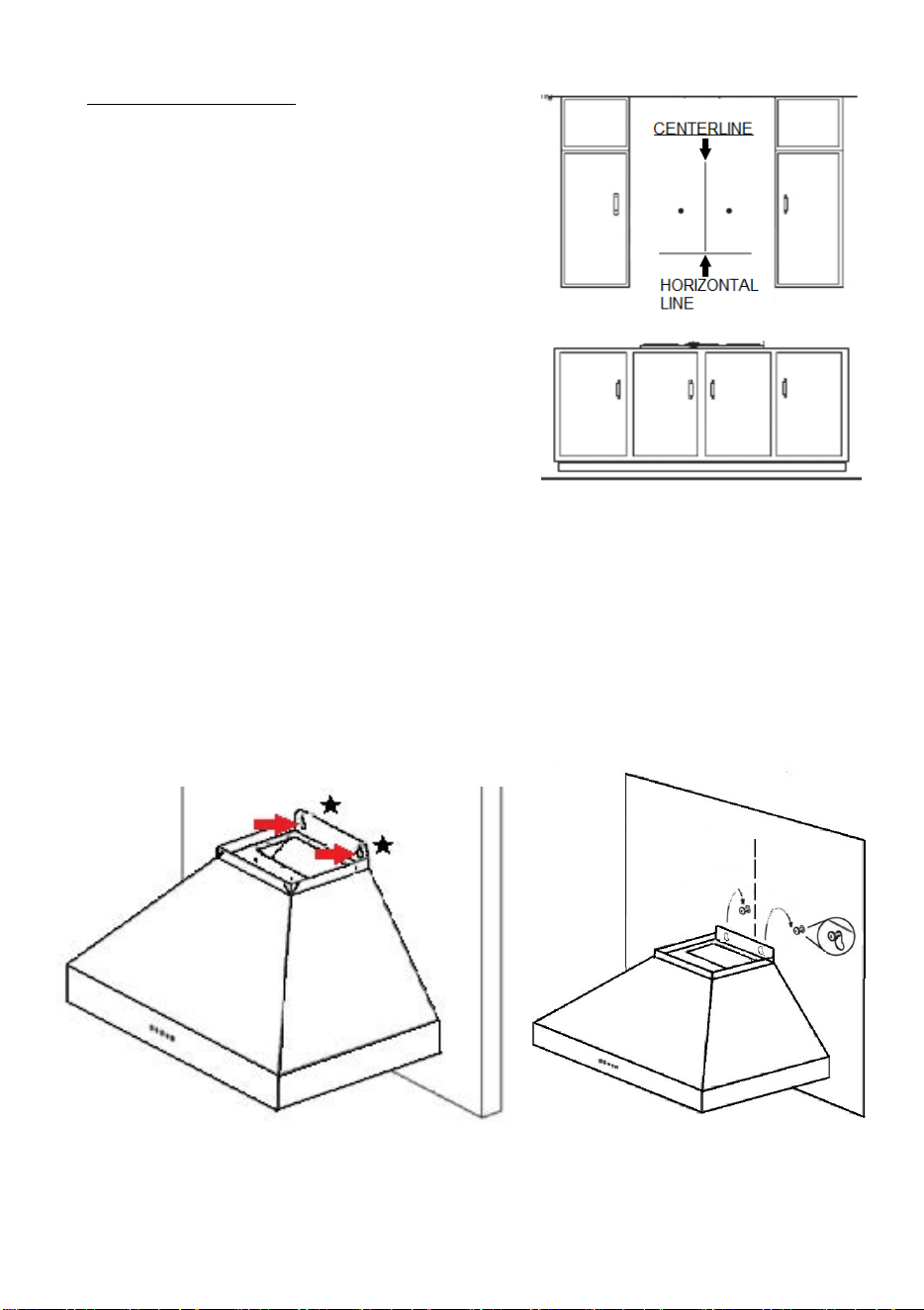
RANGE HOOD INSTALLATION
1. Find the center of the wall where you are installing
the hood. NOTES: Be sure there is sufficient bracing
to hold the weight of the unit. Draw a vertical line on
the supporting wall up to the ceiling, or as high as
practical, at the center of the area in which the hood
will be installed. Figure 1.
2. Draw a horizontal line at desired height (min 30”
above the cooktop). Figure 1.
3. Place the hood on the wall with the center to the
Figure 1.
vertical reference line and make sure the bottom part of the hood aligns with the horizontal line.
With the range in position, mark the wall at the center of the holes in the bracket and remove the
hood from the wall. Finally drill the holes and fix the expansion bolt. NOTES: Make sure you are
leaving the heads out
¼” to mount the hood. Figure 2.
4. Attach the hood body to the mounting screws on the wall. NOTES: Make sure the mounting screws
are properly leveled before tightening the screws. Figure 3.
Figure 2.
Figure
3.
5. Place chimney mounting brackets
on the wall 1/8” from the ceiling or
upper limit aligning the center with
the vertical reference line. Figure 4.
6. Fix the two brackets (Chimney
mounting bracket and Decorative
frame bracket) using the mounting
screws and drywall anchors. Figure
4.
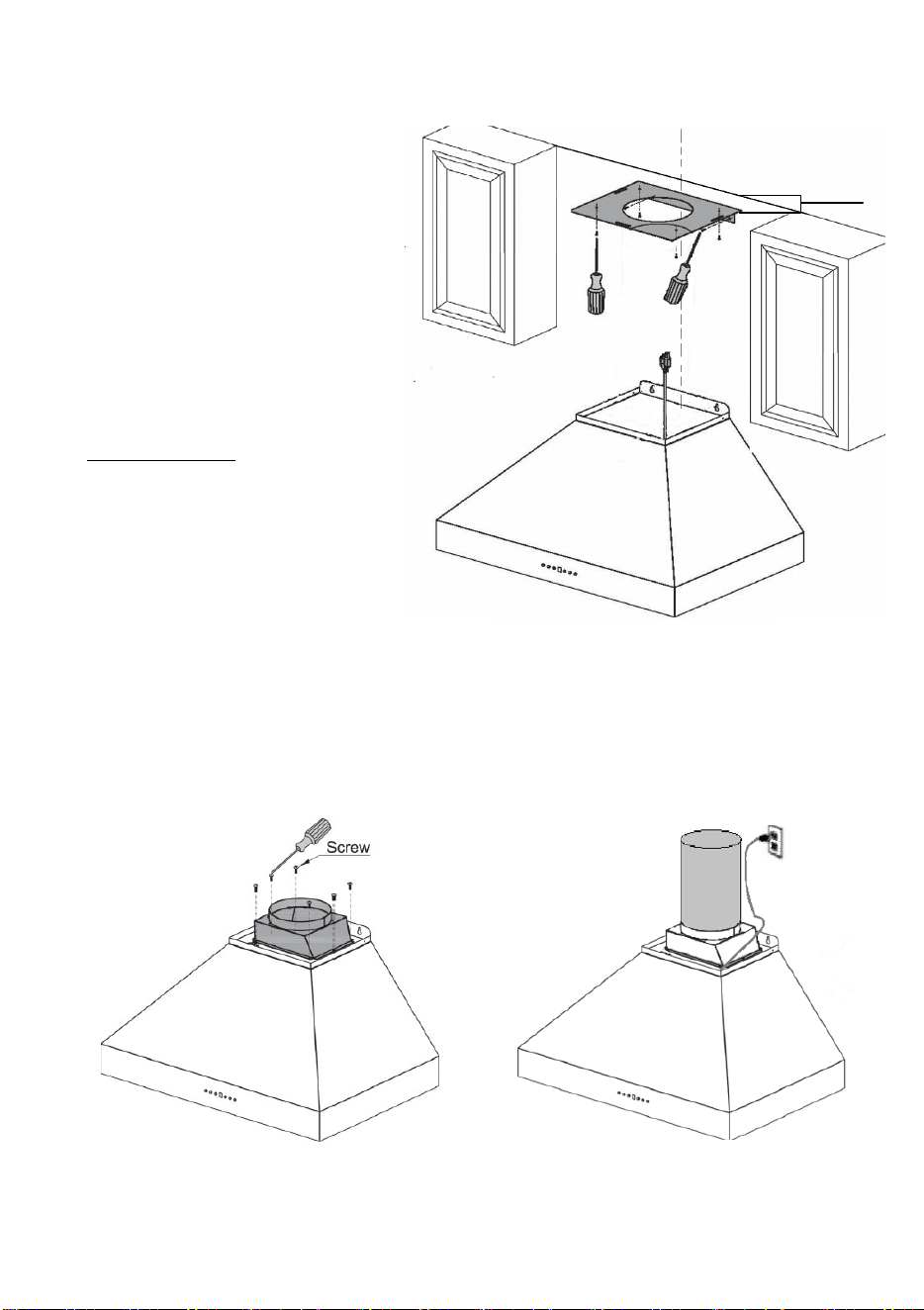
DUCT INSTALLATION
Caution: To reduce the risk of fire, use
metal ductwork only.
7. Install the air outlet adapter over
the hood with the provided screws
(φ 6” for 30” & 10’’ for 36’’,48’’ and
60’’). Figure 5.
Figure 4.
8.
Make your ducting and electrical connections. You will need to minimize the use of elbows, since
elbows and longer duct create higher static pressure. (See Connections section)
9. Connect the duct with the air outlet adapter by using foil-backed tape to seal the joints and to hold
it in place. Figure 6.
Figure 5. Figure 6.
1/8”
NOTE: PLACE THE POWER OUTLET AND POWER CORD BEHIND THE CHIMNEY. SHOWN
BELLOW.
Figure 7.
CONNECTIONS
Caution: To reduce the risk of fire, use metal ductwork is preferred.
1.
Decide where the ductwork will run between the hood and
the outside.
2.
A straight, short duct run will allow the hood to perform most
efficiently.
3.
Long duct runs, elbows, and transitions will reduce the
performance of the hood. Use as few of them as possible.
Larger ducting may be required for best performance with
longer duct runs.
4.
The air must not be discharge into a flue that is used for
exhausting fumes from appliances burning gas or other fuels"
"Regulations concerning the discharge of air have to be fulfilled.
5.
Install a roof/wall cap. Connect round metal ductwork to cap
and work back towards hood location. Use duct tape to seal the
joints between ductwork sections.
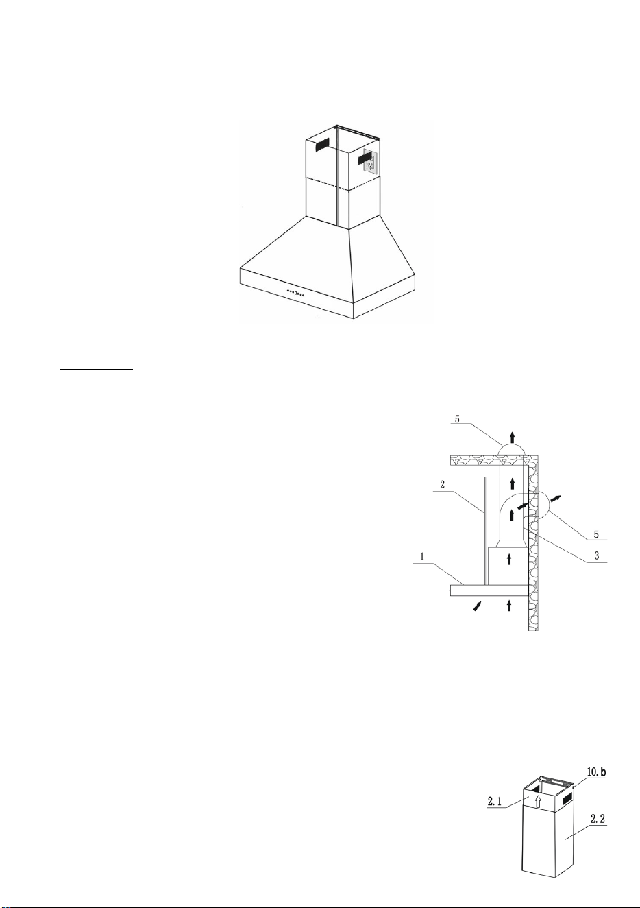
CHIMNEY ASSEMBLY
10. Install the two-part chimneys on top of the hood (2.1 & 2.2). Slide the inside
section (2.1) up until the vertical vent slots are visible, attach top portion to
chimney mounting bracket with screws (10.b). Shown to the right & Figure 9.
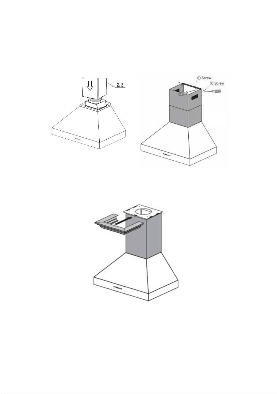
11. Slide the outer section (2.2) down the outside of the inside section (2.1). Carefully lower the
chimney to the recessed area of the hood body top and secure it in the gap of hood body top.
Figure 8 & 9.
Figure 8. Figure 9.
12.
Slide the decorative crown onto the chimney mounting bracket and secure into place. Figure 10.
Figure 10.
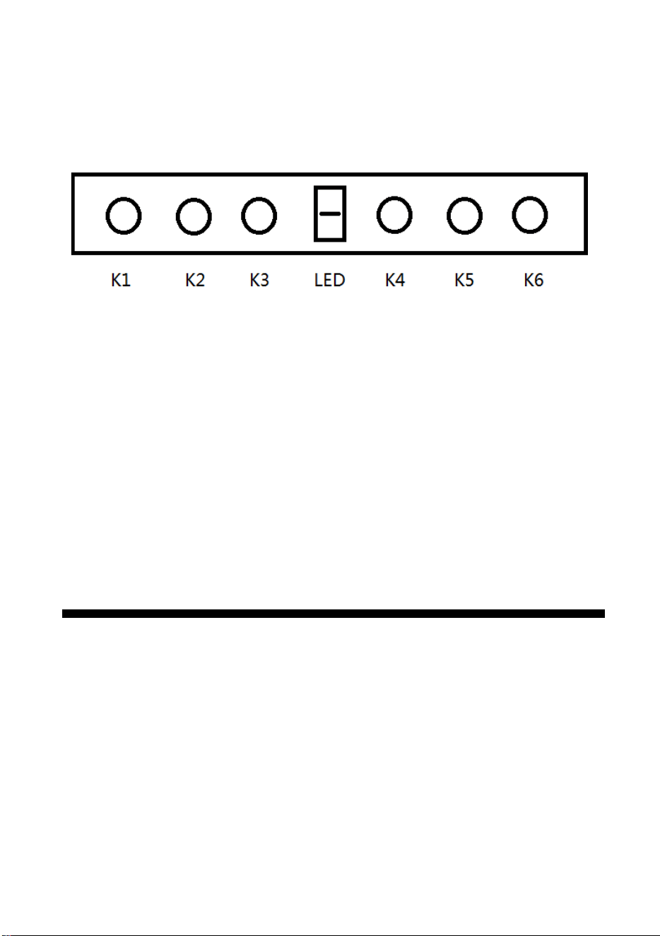
OPERATIONS
K1: Power Button/Power-off Delay Button
When the range hood is off, press this button to turn on the range hood, press K2 K3 K4 K5 to adjust
motor speed.
When the range hood is on, press this button to enter Power-off delay function, timer is 3 minutes, the
range hood will turn off automatically when time up.
K2: First Speed
K3: Second Speed
K4: Third Speed
K5: Fourth Speed
K6: Light Button. Turn on and off the light
MAINTENANCE & CLEANING
Surface Maintenance:
Clean periodically with hot soapy water and clean cotton cloth. Do not use corrosive or abrasive
detergent (e.g., comet powder scrub, EZ-Off oven cleaner), or steel wool/scoring pads which will
scratch and damage surface.
For heavier soil use liquid degreaser such as ‘Formula 409’ or ‘Fantastic’ brand cleaner.
After cleaning, you may use nonabrasive stainless-steel polish/cleaners such as 3M or ZEP, to polish
and buff out the stainless luster and grain. Always scrub lightly, with clean cotton cloth, and with the
grain
Filters:
The Filters fitted by the factory are intended to filter out residue and grease from cooking. It need not be
replaced on a regular basis but are required to be kept clean.
Filters should be cleaned after every 30 hours of use.

Remove and clean by hand in a basin of hot soapy water. The filter is also dishwasher safe.
If heavily soiled, spray ‘Formula 409’ or equivalent degreasing detergent and leave to soak.
Dry filters and re-install before using hood.
Hood Cleaning
The saturation of greasy residue in the blower and filters may cause increased inflammability. Always
keep unit clean and free of grease and residue build-up to prevent possible fires.
Filters must be cleaned periodically and free from accumulation of cooking residue (see cleaning
instructions inside). Old and worn filters must be replaced immediately. Do not operate blowers when
filters are removed. Never disassemble parts to clean without proper instructions. Disassembly is
recommended to be performed by qualified personnel only. Call our service center for removal
instructions.
Stainless steel is one of the easiest materials to keep clean. Occasional care will help preserve its fine
appearance.
Cleaning tips:
* Hot water with soap or detergent is all that is usually needed.
* Rinse with clear water. Wipe dry with a clean, soft cloth to avoid water marks.
* For discolorations or deposits that persist, use a non-scratching household cleanser or stainless-steel
polishing powder with a little amount of water and a soft cloth.
* For stubborn stain, use a plastic scouring pad or soft bristle brush together with cleanser and water.
Rub lightly in direction of polishing lines or “grain” of the stainless finish. Avoid using too muc
h
p
ressure that may mar the surface.
* Do not allow deposits to remain for long periods of time.
* Do not use ordinary steel wool or steel brushes. Small bits of steel may adhere to the surface causing
rust.
* Do not allow salt solutions, disinfectants, bleaches, or cleaning compounds to remain in contact with
stainless steel for extended periods. Many of these compounds contain chemicals that may be
harmful. Rinse with water after exposure and wipe dry with a clean cloth.
* Painted surfaces should be cleaned with warm water and mild detergent only.
LIGHT bulbs
WARNING: Please ensure lights have been switched off for some time and the power source has been
disconnected before replacing any globes. Please be aware that the light will retain heat for
a short period of time after being switched off.
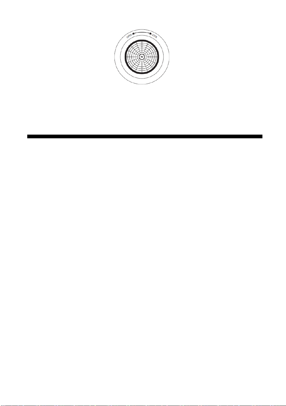
Step 1: Turn anti-clockwise to open
Step 2: Take the existing globe out
Step 3: Insert a new globe (1.5W GU10 LED) and turn clockwise in lock position
TROUBLESHOOTING
My hood is operating, but the air is moving slower than normal.
Check the filter for buildup and clean or replace it if needed. If the difficulty persists, check for
obstructions in the ductwork. A common obstruction is buildup in the roof or wall cap, such as: bird
nests or other debris.
What is make-up air?
When the range hood ventilates the air out of the room, the air vented must be replaced, this is called
make-up air. We do not currently provide a make-up air unit. NOTE: Always consult any applicable
building codes in your area regarding minimum and maximum air flow rates. Certain states may
require additional items such as make-up air for larger CFM range hoods (typically over 300 CFM).
My range hood will not operate.
1
. Check that there is power to the range hood. The most common issue is that the circui
t
b
reaker is off, or the fuse has blown.
2. Make sure the speed has been selected at the range hood controls.
3. Turn off power to the range hood and check that all the wires are properly connected.
My range hood is making a rattling noise.
This is probably attributed to one of the following:
1. The motor is loose – Turn off the power and remove the filter and check that all screws are
secure and tight around the motor.
2. The duct work connection is loose – Turn off the power to the unit and check that the
ductwork connection to the pipe is tight. Add duct tape is necessary.
My range hood does not have power.
1. Check e
lectrical connections.
2. Check that all connections to the circuit board are secure.

3. If the problem persists, please contact Forno Technical Support.
My range hood is not pulling.
• Was the unit plugged in and was the fan checked before installation?
• What distance is the hood mounted above the cook top?
• Is the range hood width the correct size for the cook top?
• Does the hood have enough BTU output in relationship to either their gas or electric stove cook
top?
• BTU output per burner/100 - for gas
• Wattage output per burner/10 - for electric
• Are the baffle filters or mesh filters installed correctly? When were they last cleaned?
• Is the ducting clear?
• Is the damper opening properly once the hood is turned on?
• Is there air coming off the top of the hood?
• Is there air coming out of the upper chimney section?
• When tissue is placed on the baffle filters under the hood, does it hold the tissue?
• How many elbows and how long is the ducting run?
• Should be no more than 2-3 elbows, for every elbow subtract 15 feet. (See Duct Run
Calculation Section).

FRHWM5094-36, FRHWM5094-48, FRHWM5094-60
WIRE DIAGRAM
FRHWM5094-30
