OPERATOR'S MANUAL
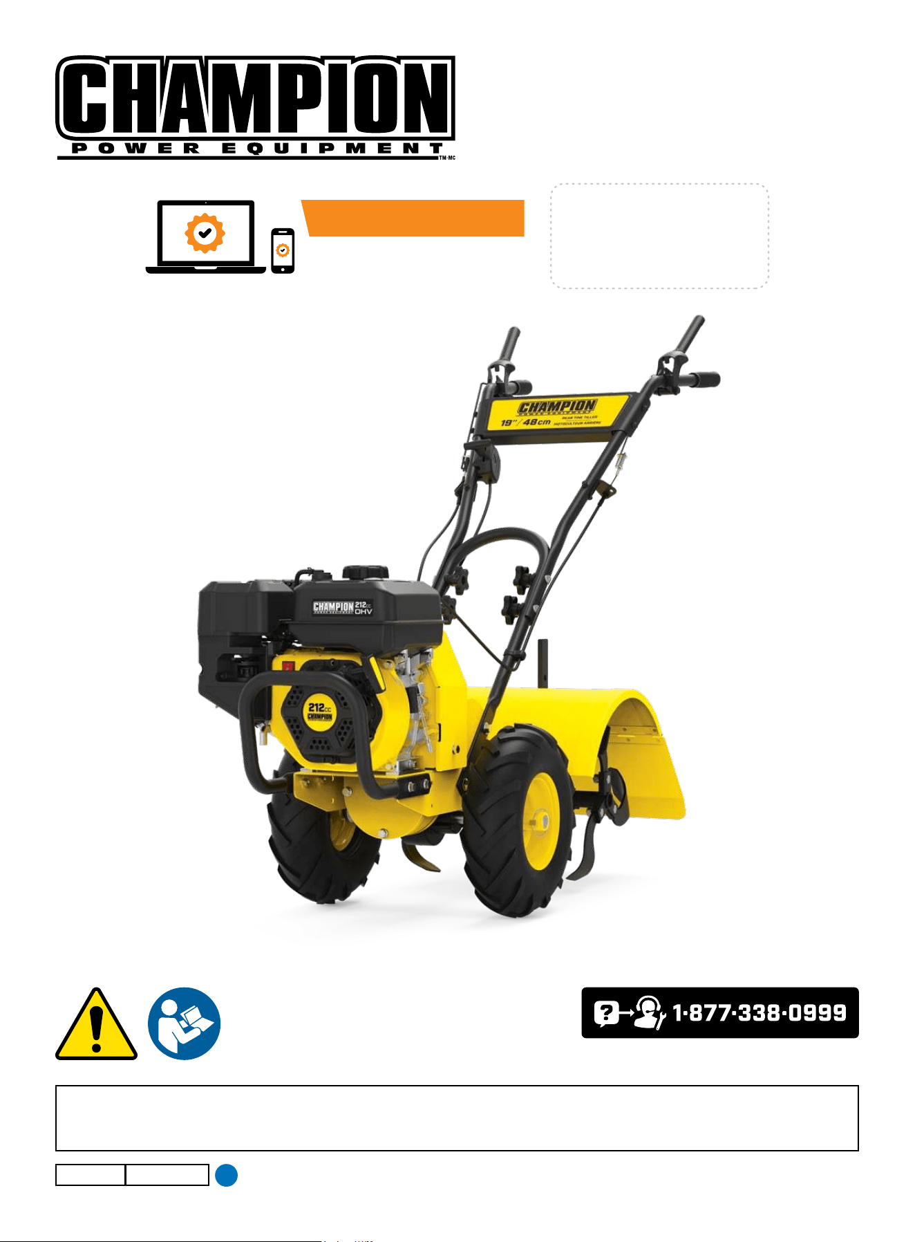
MODEL #201464
REAR TINE TILLER
or visit championpowerequipment.com
READ AND SAVE THIS MANUAL. This manual contains important safety precautions which should be read and understood before operating the product. Failure to
do so could result in serious injury. This manual should remain with the product.
Specifications, descriptions and illustrations in this manual are as accurate as known at the time of publication, but are subject to change without notice.
Champion Power Equipment, Inc.
5027-M-OP REV 20241220
EN
ACTIVATE YOUR WARRANTY
by registering your product:
championpowerequipment.com
SERIAL NO.

201464 - REAR TINE TILLER
TABLE OF CONTENTS
2
TABLE OF CONTENTS
Introduction
................................................... 3
Safety Definitions
.......................................... 3
Important Safety Instructions
....................... 4
Training .............................................................4
Preparation .........................................................4
Operation ...........................................................5
Maintenance and Storage .........................................6
Fuel Safety .........................................................6
Safety Symbols .....................................................8
Operation Symbols ............................................... 10
Quickstart Label Symbols........................................ 11
Safety Labels ..................................................... 12
Controls and Features ................................. 14
Tiller .............................................................. 14
Engine ............................................................ 14
Parts Included .................................................... 15
Tools Included .................................................... 15
Tools Needed ..................................................... 15
Assembly ..................................................... 16
Unpacking ........................................................ 16
Attach Lower Handle ............................................. 16
Install the Wheels ................................................ 16
Install the Tines .................................................. 16
Install the Tine Shield ............................................ 16
Install the Depth Regulator ...................................... 17
Attach Upper Handle ............................................. 17
Attach Speed Control ............................................ 17
Attach Front Bumper ............................................. 17
Introduction ....................................................... 18
Wheel Drive Pins ................................................. 18
Forward Lever .................................................... 19
Reverse Lever .................................................... 19
Depth Regulator Lever Adjustment .............................. 19
Handlebar Height Adjustment .................................... 20
Operation ..................................................... 20
Introduction ....................................................... 20
Add Engine Oil .................................................... 20
Add Fuel
.......................................................... 21
Transmission Gear Oil ............................................ 22
Starting the Engine ............................................... 22
Stopping the Engine and the Tiller
............................... 23
Operation at High Altitude ....................................... 24
Tilling Tips and Techniques
......................... 24
Tilling Depths ..................................................... 24
Choosing Correct Wheel and Tine Speeds ...................... 24
Let the Tiller Do the Work ........................................ 24
Avoid Tilling Soggy, Wet Soil ..................................... 24
Preparing Seedbeds .............................................. 25
Cultivating ........................................................ 25
Tilling on Slopes .................................................. 25
Clearing the Tines ................................................ 25
Loading and Unloading the Tiller ................................ 26
Maintenance ................................................ 26
Tiller Lubrication ................................................. 27
Check for Oil Leaks .............................................. 27
Check Hardware.................................................. 27
Check Tire Pressure .............................................. 27
Transmission Gear Oil Service ................................... 28
Tines .............................................................. 28
Checking and Adjusting Forward Drive Belt Tension ........... 29
Belt Tension Adjustment ......................................... 30
Change Forward/Reverse Belts ................................. 30
Engine Oil Service ................................................ 32
Air Cleaner Maintenance ......................................... 33
Spark Plug Service ............................................... 33
Spark Arrester Screen Service .................................. 33
Storage ........................................................ 33
Tiller Storage ..................................................... 34
Engine Stored for Less than 30 Days ........................... 34
Engines Stored for Over 30 Days ................................ 34
Specifications .............................................. 35
Tiller Specifications .............................................. 35
Engine Specifications ............................................ 35
Fuel Specifications ............................................... 35
Troubleshooting ........................................... 36
Difficulty Starting Engine (Recoil) ............................... 37
Gasoline Engine: No Power ...................................... 38
Gasoline Engine Running Roughly ............................... 38
Stops Suddenly When Running .................................. 39
Engine is Overheating
............................................ 39
FOR PARTS BREAKDOWN
Search by model number at
championpowerequipment.com

201464 - REAR TINE TILLER
INTRODUCTION
3
INTRODUCTION
Congratulations on your purchase of a Champion Power Equipment
(CPE) product. CPE designs, builds, and supports all of our
products to strict specifications and guidelines. With proper
product knowledge, safe use, and regular maintenance, this
product should bring years of satisfying service.
Every effort has been made to ensure the accuracy and
completeness of the information in this manual at the time of
publication, and we reserve the right to change, alter and/or
improve the product and this document at any time without prior
notice.
Since CPE highly values how our products are designed,
manufactured, operated and are serviced, and also highly value
your safety and the safety of others, we would like you to take the
time to review this product manual and other product materials
thoroughly and be fully aware and knowledgeable of the assembly,
operation, dangers and maintenance of the product before use.
Fully familiarize yourself, and make sure others who plan on
operating the product fully familiarize themselves too, with the
proper safety and operation procedures before each use. Please
always exercise common sense and always err on the side
of caution when operating the product to ensure no accident,
property damage, or injury occurs. We want you to continue to use
and be satisfied with your CPE product for years to come.
When contacting CPE about parts and/or service, you will need to
supply the complete model and serial numbers of your product.
Transcribe the information found on your product’s nameplate
label to the table below.
CPE TECHNICAL SUPPORT TEAM
1-877-338-0999
MODEL NUMBER
201464
SERIAL NUMBER
DATE OF PURCHASE
PURCHASE LOCATION
SAFETY DEFINITIONS
The purpose of safety symbols is to attract your attention to
possible dangers. The safety symbols, and their explanations,
deserve your careful attention and understanding. The safety
warnings do not by themselves eliminate any danger. The
instructions or warnings they give are not substitutes for proper
accident prevention measures.
DANGER
DANGER indicates a hazardous situation which,if not avoided,
will result in death or serious injury.
WARNING
WARNING indicates a hazardous situation which, if not
avoided, could result in death or serious injury.
CAUTION
CAUTION indicates a hazardous situation which, if not avoided,
could result in minor or moderate injury.
NOTICE
NOTICE indicates information considered important, but not
hazard-related (e.g., messages relating to property damage).
201464 - REAR TINE TILLER
IMPORTANT SAFETY INSTRUCTIONS
4
IMPORTANT SAFETY INSTRUCTIONS
WARNING
Cancer and Reproductive Harm –
www.P65Warnings.ca.gov
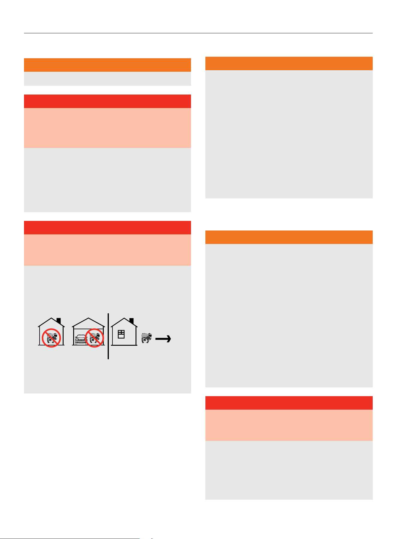
DANGER
Engine exhaust contains carbon monoxide, a colorless,
odorless, poison gas. Breathing carbon monoxide will cause
nausea, dizziness, fainting or death. If you start to feel dizzy or
weak, get to fresh air immediately.
Operate tiller outdoors only in a well ventilated area.
DO NOT operate the tiller inside any building, including
garages, basements, crawlspaces and sheds, enclosure or
compartment.
DO NOT allow exhaust fumes to enter a confined area through
windows, doors, vents or other openings.
DANGER
Using an engine indoors CAN KILL YOU IN MINUTES. Engine
exhaust contains carbon monoxide. This is a poison you cannot
see or smell.
NEVER use inside a home or garage, EVEN IF doors and
windows are open.
ONLY use OUTSIDE and far away from windows, doors,
and vents.
Install battery-operated carbon monoxide alarms or plug-in
carbon monoxide alarms with battery back-up according to the
manufacturer’s instructions.
Training
WARNING
1. Carefully read this Operator’s Manual and any other
literature you may receive. Be thoroughly familiar with the
controls and the proper use of the tiller and its engine.
Know how to stop the unit and disengage the controls
quickly.
2. Never allow children under age 16 to operate the tiller.
Never allow adults to operate the tiller without proper
instruction.
3. Always keep the area of operation clear of all persons,
children, and pets.
4. The operator or user is responsible for accidents or
hazards occurring to other people, their property, and
themselves.
Preparation
WARNING
1. Thoroughly inspect the area where the tiller is to be used
and remove all foreign objects.
2. Be sure all tiller controls are released and both wheels are
in the Wheel Drive position before starting the engine.
3. Do not operate the tiller without wearing adequate outer
garments. Avoid loose garments or jewelry that could get
caught in moving parts.
4. Do not operate the tiller when barefoot or wearing
sandals, sneakers, or light footwear. Wear protective
footwear that will improve footing on slippery surfaces.
5. Do not till near underground electric cables, telephone
lines, pipes or hoses. If in doubt, contact your telephone
or utility company.
6. Never make adjustments when engine is running.
DANGER
Rotating parts can entangle hands, feet, hair, clothing and/or
accessories. Traumatic amputation or severe laceration can
result.
Keep hands and feet away from rotating parts.
Tie up long hair and remove jewelry.
Operate equipment with guards in place.
DO NOT wear loose-fitting clothing, dangling drawstrings or
items that could become caught.

201464 - REAR TINE TILLER
IMPORTANT SAFETY INSTRUCTIONS
5
Operation
WARNING
1. Do not put hands or feet near or under rotating parts.
2. DO NOT till in reverse.
3. Exercise extreme caution when on or crossing gravel
drives, walks, or roads. Stay alert for hidden hazards or
traffic. Do not carry passengers.
4. After striking a foreign object, stop the engine, remove
the wire from the spark plug and prevent it from touching
the spark plug. Thoroughly inspect the machine for any
damage and repair the damage before restarting and
operating the machine
5. Exercise caution to avoid slipping or falling.
6. If the unit should start to vibrate abnormally, stop the
engine, disconnect the spark plug wire and prevent it from
touching the spark plug, and check immediately for the
cause. Vibration is generally a warning of trouble.
7. Stop the engine, disconnect the spark plug wire and
prevent it from touching the spark plug, whenever you
leave the operating position, before unclogging the tines,
or when making any repairs, adjustments or inspections.
8. When leaving the machine unattended, stop the engine.
Disconnect the spark plug wire and move it away from
the spark plug. Be sure that both wheels are in the Wheel
Drive position.
9. Before cleaning, repairing, or inspecting, stop the
engine and make certain all moving parts have stopped.
Disconnect the spark plug wire and prevent it from
touching the spark plug to prevent accidental starting.
10. The flap on the tine hood must be down when operating
the tiller.
11. Never operate the tiller under engine power if the
wheels are in the Freewheel position. In the Freewheel
position, the wheels will not hold the tiller back and the
revolving tines could propel the tiller rapidly, possibly
causing loss of control. Always engage the wheels with
the wheel drive pins in the Wheel Drive position before
starting the engine or engaging the tines⁄wheels with the
forward or reverse controls.
12. Always be aware that the tiller may unexpectedly
bounce upward or jump forward if the tines should
strike extremely hard packed soil, frozen ground,
or buried obstacles like large stones, roots, or
stumps. If in doubt about the tilling conditions, always
use the following operating precautions to assist you in
maintaining control of the tiller:
12a. Use shallower depth regulator settings, working
gradually deeper with each pass.
12b. Use slower engine speeds.
12c. Clear the tilling area of all large stones, roots or other
debris.
12d. Avoid using downward pressure on the handlebars.
If need be, use slight upward pressure to keep the
tines from digging too deeply.
12e. In an emergency, stop the tines and wheels by
releasing whichever lever is engaged. Do not attempt
to restrain the tiller.
13. Do not overload the tiller’s capacity by attempting to till
too deeply at too fast a rate.
14. Never operate the tiller at high transport speeds on hard
or slippery surfaces. Look behind and use care when
backing up.
15. Do not operate the tiller on a slope that is too steep for
safety (greater than 15 degrees). When on slopes, slow
down and make sure you have good footing. Never permit
the tiller to freewheel down slopes.
16. Never allow bystanders near the unit.
17. Never operate the tiller without good visibility or light.
18. Never operate the tiller if you are tired; or under the
influence of alcohol, drugs or medication.
19. Do not touch engine parts which may be hot from
operation. Let parts cool down sufficiently.
20. Always remember you can always stop the tines and
wheels by releasing control levers (whichever control is
engaged).
21. Never pull the tiller towards you.
22. Start the engine carefully according to instructions and
with feet well away from the tines.
23. Never pick up or carry a machine while the engine is
running.

201464 - REAR TINE TILLER
IMPORTANT SAFETY INSTRUCTIONS
6
WARNING
Spark from removed spark plug wire can result in fire or
electrical shock.
When servicing the engine:
Disconnect the spark plug wire and place it where it cannot
contact the plug or any other metal object.
DO NOT check for spark with the plug removed.
Use only approved spark plug testers.
Maintenance and Storage
WARNING
1. Check all nuts, bolts, and screws for proper tightness to
be sure the equipment is in safe working condition.
2. Never store the tiller with fuel in the fuel tank inside a
building where ignition sources are present, such as
hot water and space heaters, furnaces, clothes dryers,
stoves, electric motors, etc. Allow the engine to cool
before storing the unit in any enclosure.
3. To reduce the chances of a fire, keep the engine free of
grass, leaves, or excessive grease.
4. Store gasoline in a cool, well-ventilated area, safely away
from any spark- or flame-producing equipment. Store
gasoline in an approved container, safely away from the
reach of children.
5. Never perform maintenance while the engine is running or
the spark plug wire is connected, except when specifically
instructed to do so.
6. If the fuel tank has to be drained, do this outdoors.
WARNING
Do not tamper with the engine-governor settings on the
machine.
The engine-governor controls the maximum safe operation
speed and protects the engine and all moving parts from
damage caused by overspeed. Tampering with the engine-
governor speed will void your warranty.
Fuel Safety
DANGER
GASOLINE AND GASOLINE VAPORS ARE HIGHLY
FLAMMABLE AND EXPLOSIVE.
Fire or explosion can cause severe burns or death.
Gasoline and gasoline vapors:
– Gasoline vapors are highly flammable and explosive.
– Gasoline vapors can cause a fire or explosion if ignited.
– Gasoline is a liquid fuel and the resulting gasoline vapors can
ignite and cause a fire or explosion.
– Gasoline is a skin irritant and needs to be cleaned up
immediately if spilled on skin or clothes.
– Gasoline has a distinctive odor, this will help detect potential
leaks quickly.
– In any petroleum gas fire, flames should not be extinguished
unless by doing so the fuel supply valve can be turned OFF.
This is because if a fire is extinguished and a supply of fuel is
not turned OFF, then an explosion hazard could be created.
– Gasoline vapors expand and contract with ambient
temperatures. Never fill the gasoline tank past the red FULL
indicator on the fuel filter, as gasoline vapors needs room to
expand if temperatures rise.
WARNING
When adding or removing gasoline:
DO NOT light or smoke cigarettes.
Always stop the engine and allow to cool for a minimum of two
minutes before refueling.
Always loosen gasoline cap slowly to release vapor pressure
and to keep fuel from escaping around the gasoline cap.
Always replace and tighten the gasoline cap securely after
fueling.
Never remove the gasoline cap or add gasoline while the
engine is running or when the engine is hot.
Only fill or drain gasoline outdoors in a well-ventilated area.
DO NOT pump gasoline directly into the tiller at the gas station.
Always store gasoline in an EPA/CARB compliant container or
to transfer the gasoline to the engine.
DO NOT overfill the gasoline tank.
Always keep gasoline away from sparks, open flames, pilot
lights, heat and other sources of ignition.

201464 - REAR TINE TILLER
IMPORTANT SAFETY INSTRUCTIONS
7
WARNING
When starting the tiller:
DO NOT attempt to start a damaged tiller.
Always check that the gasoline cap, air filter, spark plug, fuel
lines and exhaust system are properly in place.
Always allow spilled gasoline to evaporate fully before
attempting to start the engine.
Always be certain that the tiller is resting firmly on level
ground.
WARNING
When operating the tiller:
DO NOT tip the tiller forward during operation.
WARNING
When transporting or servicing the tiller:
Always check that the fuel valve is in the OFF position and the
gasoline tank is empty.
Disconnect the spark plug wire.
WARNING
When storing the tiller:
Always store away from sparks, open flames, pilot lights, heat
and other sources of ignition.
Never store tiller or gasoline near furnaces, water heaters,
or any other appliances that produce heat or have automatic
ignitions.
WARNING
Never use a gasoline container, gasoline tank, or any other fuel
item that is broken, cut, torn or damaged.
201464 - REAR TINE TILLER
SAFETY DEFINITIONS
8
Safety Symbols
Some of the following symbols may be used on this product. Please study them and learn their meaning. Proper interpretation of
these symbols will allow you to more safely operate the product.
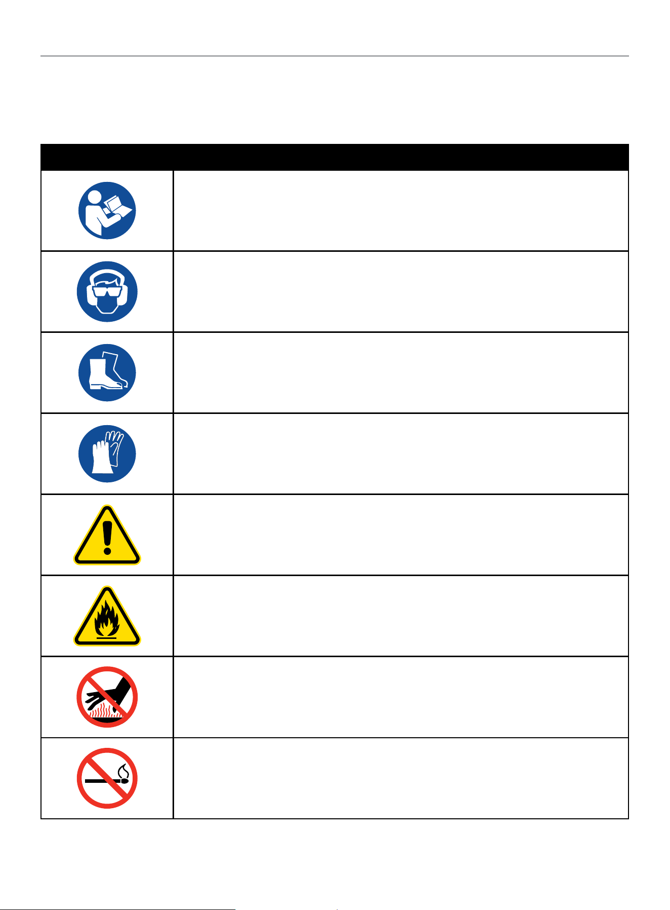
SYMBOL MEANING
Read Operator’s Manual. To reduce the risk of injury, user must read and understand operator’s manual
before using this product.
Eye and Ear Protection. Always wear safety goggles or safety glasses with side shields, and as
necessary a full face-shield as well as full ear protection when operating this product.
Footwear. Always wear safety shoes or heavy boots when operating the machine.
Gloves. Always wear nonslip, heavy-duty protective gloves when operating this product.
Safety Alert. Precautions that involve your safety.
Risk of Fire. Fuel and its vapors are extremely flammable and explosive. Fire can cause severe burns or
death. Do not add fuel while the product is operating or still hot.
Hot Surface. To reduce the risk of injury or damage, avoid contact with any hot surface.
Open Flame Alert. Fuel and its vapors are extremely flammable and explosive. Keep fuel away from
smoking, open flames, sparks, pilot lights, heat, and other ignition sources.
201464 - REAR TINE TILLER
SAFETY DEFINITIONS
9
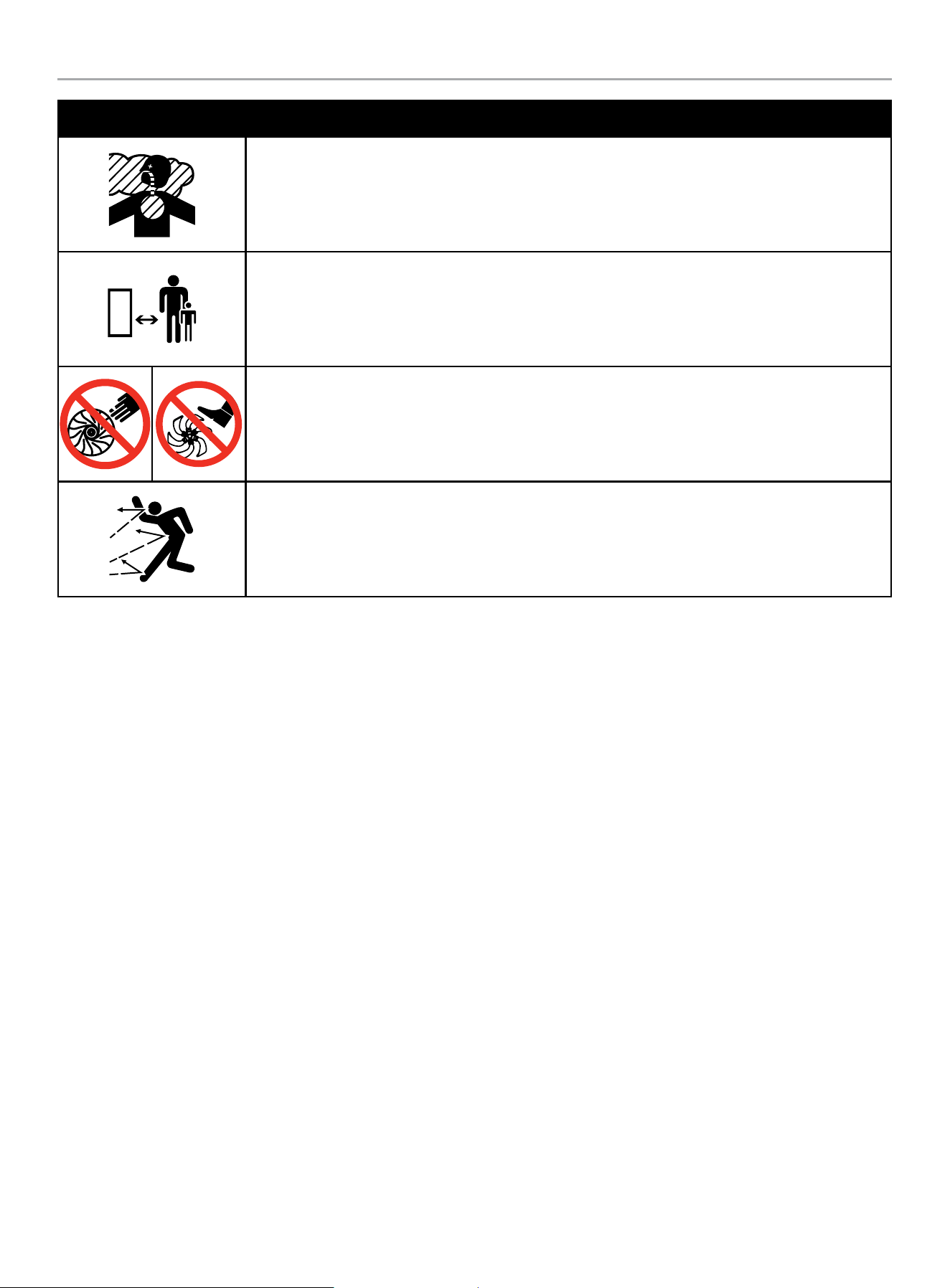
SYMBOL MEANING
Toxic Fumes. The engine exhaust from this product contains chemicals known to the state of California
to cause cancer and birth defects and other reproductive harm.
Risk of Asphyxiation. This engine emits carbon monoxide, an odorless, colorless poison gas. Breathing
carbon monoxide can cause nausea, fainting or death. Use only in a well ventilated area
Clearance. Keep all objects including others at least 50 feet (15m) from this machine.
Amputation Hazard. Rotating parts can entangle hands, feet, hair, clothing and/or accessories.
Traumatic amputation or severe laceration can result.
Thrown Objects. This machine may pick up and throw objects which can cause personal injury.
Check the work area before each use. Remove all objects such as rocks (where possible), broken glass,
nails, wire, or string which can be thrown or become entangled in the machine.
201464 - REAR TINE TILLER
SAFETY DEFINITIONS
10
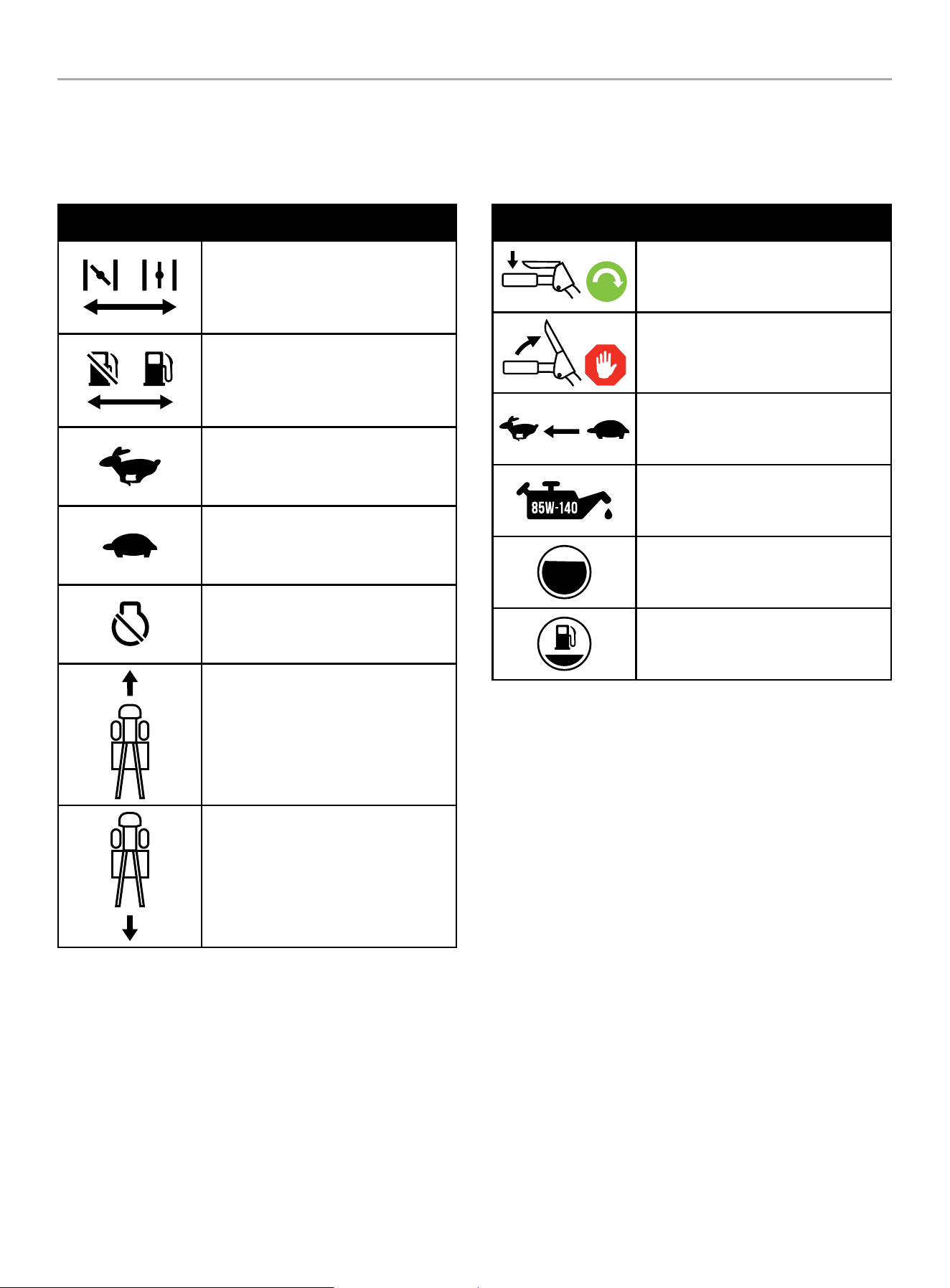
Operation Symbols
Some of the following symbols may be used on this product. Please study them and learn their meaning. Proper interpretation of
these symbols will allow you to more safely operate the product.
SYMBOL MEANING
Choke Lever
CHOKE: left position
RUN: right position
Fuel Valve
CLOSED: left position
OPEN: right position
Throttle Lever
FAST: left position
Throttle Lever
SLOW: right position
Stop
Forward
Reverse
SYMBOL MEANING
Engage Wheels and Tines
Disengage Wheels and Tines
Speed
Transmission Gear Oil. API rated GL-4
or GL-5 Viscosity of SAE 140, SAE 85W-
140 or SAE 80W-90.
Gasoline Tank: Full
Gasoline Tank: Empty

201464 - REAR TINE TILLER
SAFETY DEFINITIONS
11
Quickstart Label Symbols
Some of the following symbols may be used on this product. Please study them and learn their meaning. Proper interpretation of these
symbols will allow you to more safely operate the product.
Starting the Engine
1. Check Oil Level. Recommended oil is 10W-30. The engine can
be seriously damaged without oil. Always check the oil level
before using. The machine must be resting firmly on level
ground when checking.
2. Add gasoline with a minimum octane rating of 87 and an
ethanol content of less than 10% by volume.
3. Move the choke lever to “CHOKE” position.
4. Move the throttle lever to “FAST” position.
5. Move the fuel valve to “OPEN” position.
6. Pull starter cord.
7. Move the choke lever to “RUN” position.
Stopping the Engine
In an emergency, turn the engine switch to the “OFF”
position.
Under normal operation:
1. Turn the fuel valve to the “OFF” position.
2. Let the engine run until fuel starvation has stopped the
engine. This usually takes few minutes.
Important: Always ensure that the fuel valve is in the “OFF”
position when the engine is not in use.
2197-L-OP-C
1
10W-30
5
1
2
3
7
42
6
201464 - REAR TINE TILLER
SAFETY DEFINITIONS
12
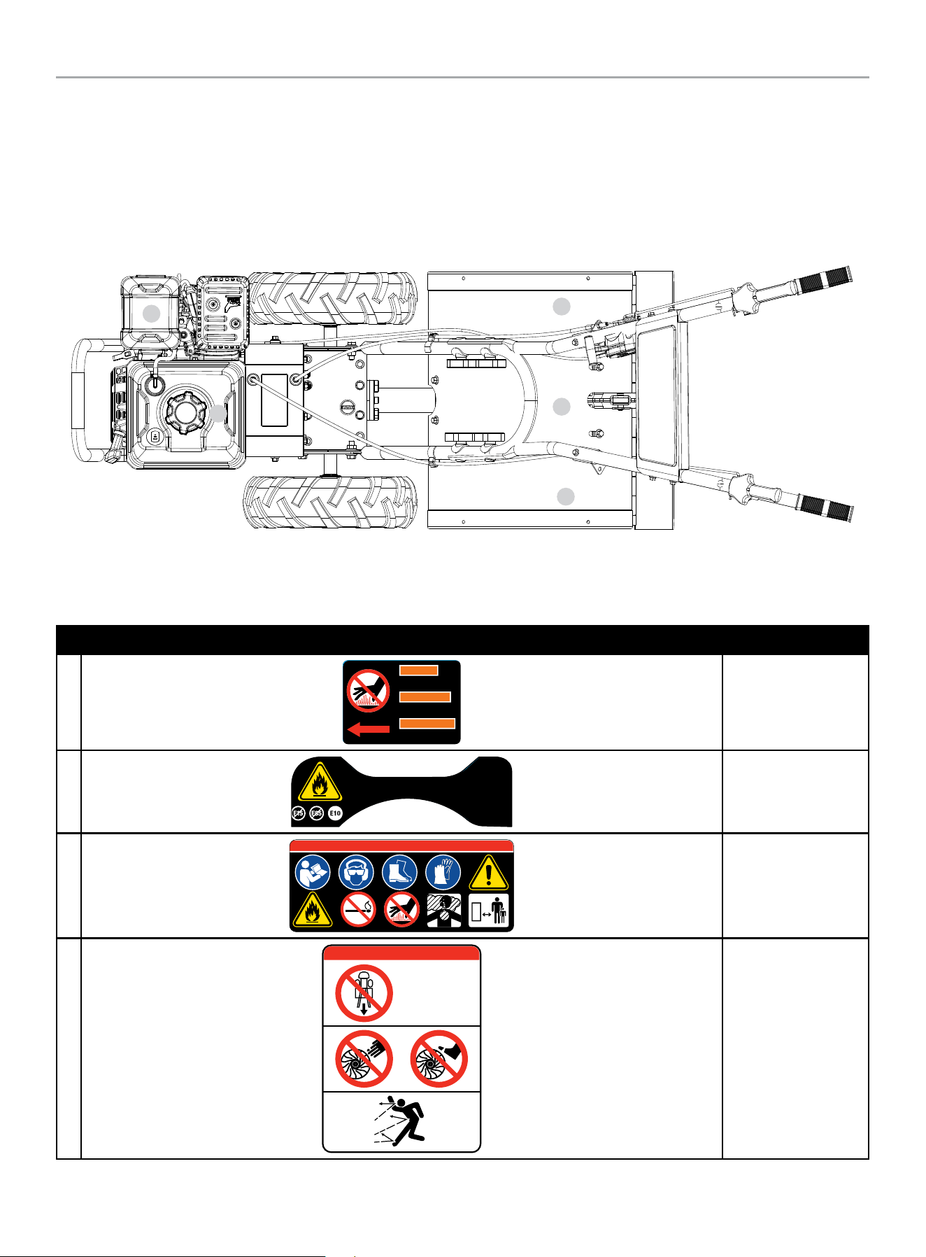
Safety Labels
These labels warn you of potential hazards that can cause serious injury. Read them carefully.
If a label comes off or becomes hard to read, contact Technical Support Team for possible replacement.
LABEL DESCRIPTION
A
1966-L-SF-B
DO NOT TOUCH!
Hot surface.
WARNING
¡NO TOCAR!
Superficie caliente.
ADVERTENCIA
AVERTISSEMENT
NE TOUCHEZ PAS!
Surface chaude.
Hot Surface
B
2018-L-OP-B
ESSENCE SANS PLOM SEULEMENT.
Indice d’octane minimal de
87. Maximum 10 % d'éthanol.
La clasificación mínimo de 87
octano. Máximo de etanol de 10%.
GASOLINA SIN PLOMO SOLAMENTE.UNLEADED FUEL ONLY.
Minimum octane rating of 87.
Maximum 10% ethanol.
Fuel
C
1253-L-SF-A
DANGER PELIGRO DANGER
Safety Icons
D
1254-L-SF-B
DO NOT till in reverse.
NO cultivar
en reversa.
NE PAS labourer en
marche arrière.
DANGER PELIGRO DANGER
Safety Icons
B
A
C
D
D
201464 - REAR TINE TILLER
SAFETY DEFINITIONS
13
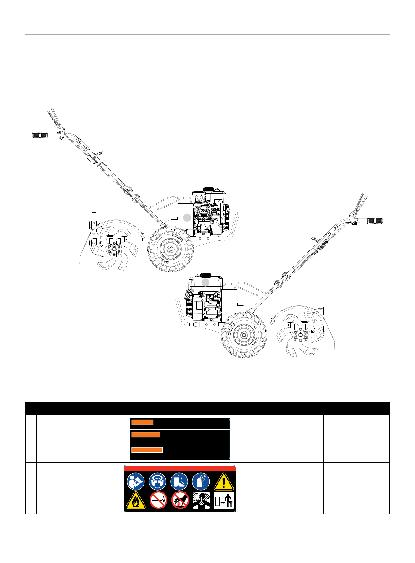
LABEL DESCRIPTION
E
WARNING
Operation of this equipment may create sparks that can start fires around
dry vegetation. A spark arrestor may be required. The operator should
contact local fire agencies for laws or regulations relating to fire prevention requirements.
ADVERTENCIA
Operación de este equipo puede crear chispas que pueden
iniciar incendios en vegetación seca. Un parachispas puede ser
requerido. El operador debería contactar las agencias locales de incendios para leyes o
regulaciones relacionadas con requisitos de prevención de incendios.
AVERTISSEMENT
Le fonctionnement de cet équipement peut créer des
étincelles qui peuvent déclencher des incendies autour de la
végétation sèche. Un pare-étincelles peut être nécessaire. L'utilisateur doit communiquer avec
le service d'incendie local pour les lois et les règlements relatifs à la prévention des incendies.
1047-L-SF-C
Combustion
F
1253-L-SF-A
DANGER PELIGRO DANGER
Safety Icons
F
E
201464 - REAR TINE TILLER
CONTROLS AND FEATURES
14
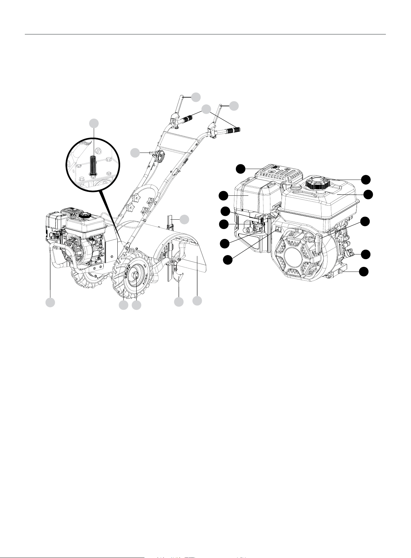
CONTROLS AND FEATURES
Read this operator’s manual before operating your tiller. Familiarize yourself with the location and function of the controls and features.
Save this manual for future reference.
Tiller
1. Front Bumper
2. Wheels
3. Wheel Lock Pins
4. Tines
5. Tine Shield
6. Depth Regulator Lever
7. Reverse Lever
8. Forward Lever
9. Handlebars
10. Speed Control
11. Gear Oil Dipstick
Engine
1. Muffler
2. Air Filter – Protects the engine by filtering dust and debris
from the intake air.
3. Throttle
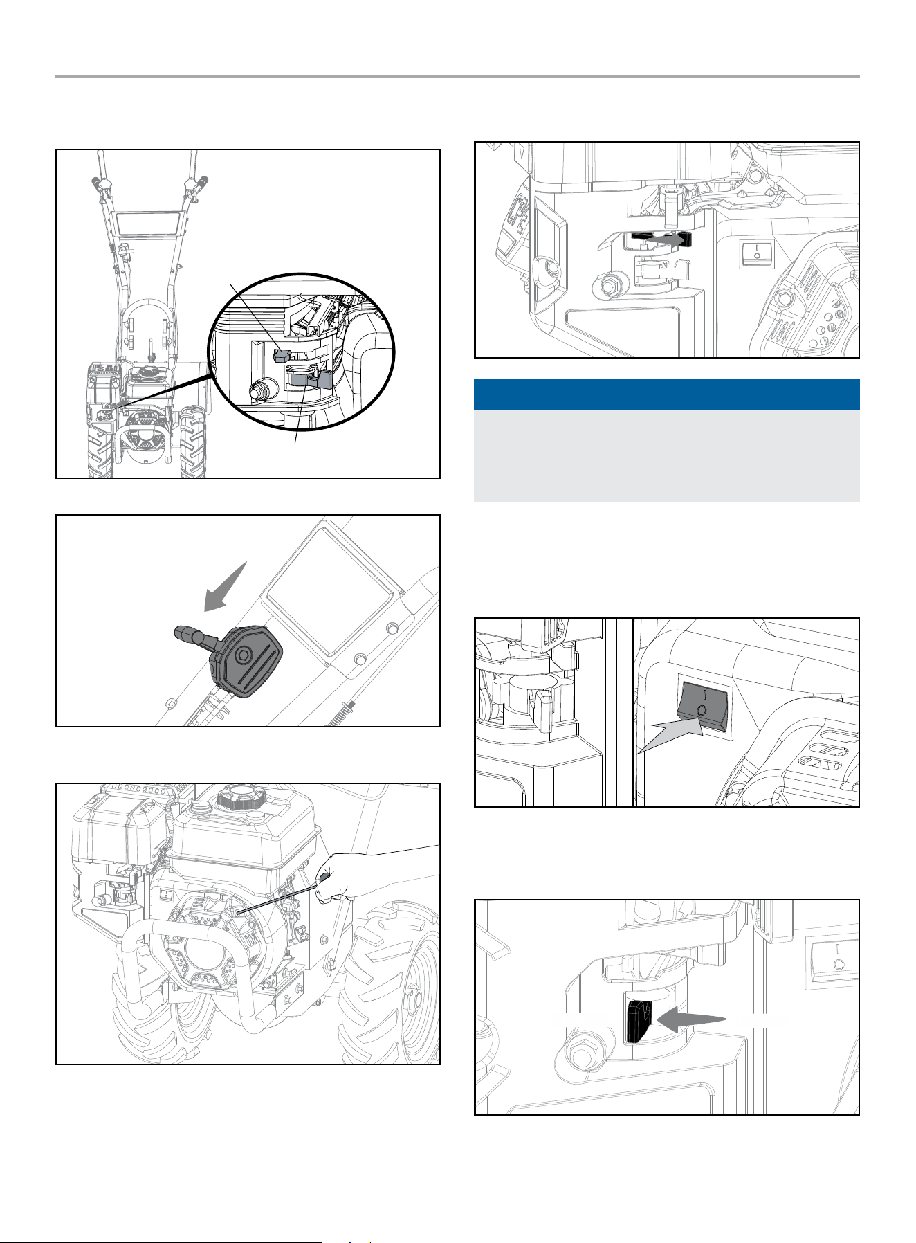
4. Choke – Used to start the engine.
5. Fuel Valve – Used to turn fuel supply on and off to engine.
6. Engine On/Off Switch
7. Oil Drain Bolt – Used to drain the oil.
8. Oil Fill Cap/Dipstick – Used to check and fill oil level.
9. Recoil Starter – Used to manually start the engine.
10. Gasoline Tank – 0.82 gal. (3.1 L)
11. Gasoline Tank Cap
1
2
3
4
5
10
1
7
8
11
9
10
2
3
5
6
6
7
8
11
9
4
201464 - REAR TINE TILLER
CONTROLS AND FEATURES
15
Parts Included
Accessories
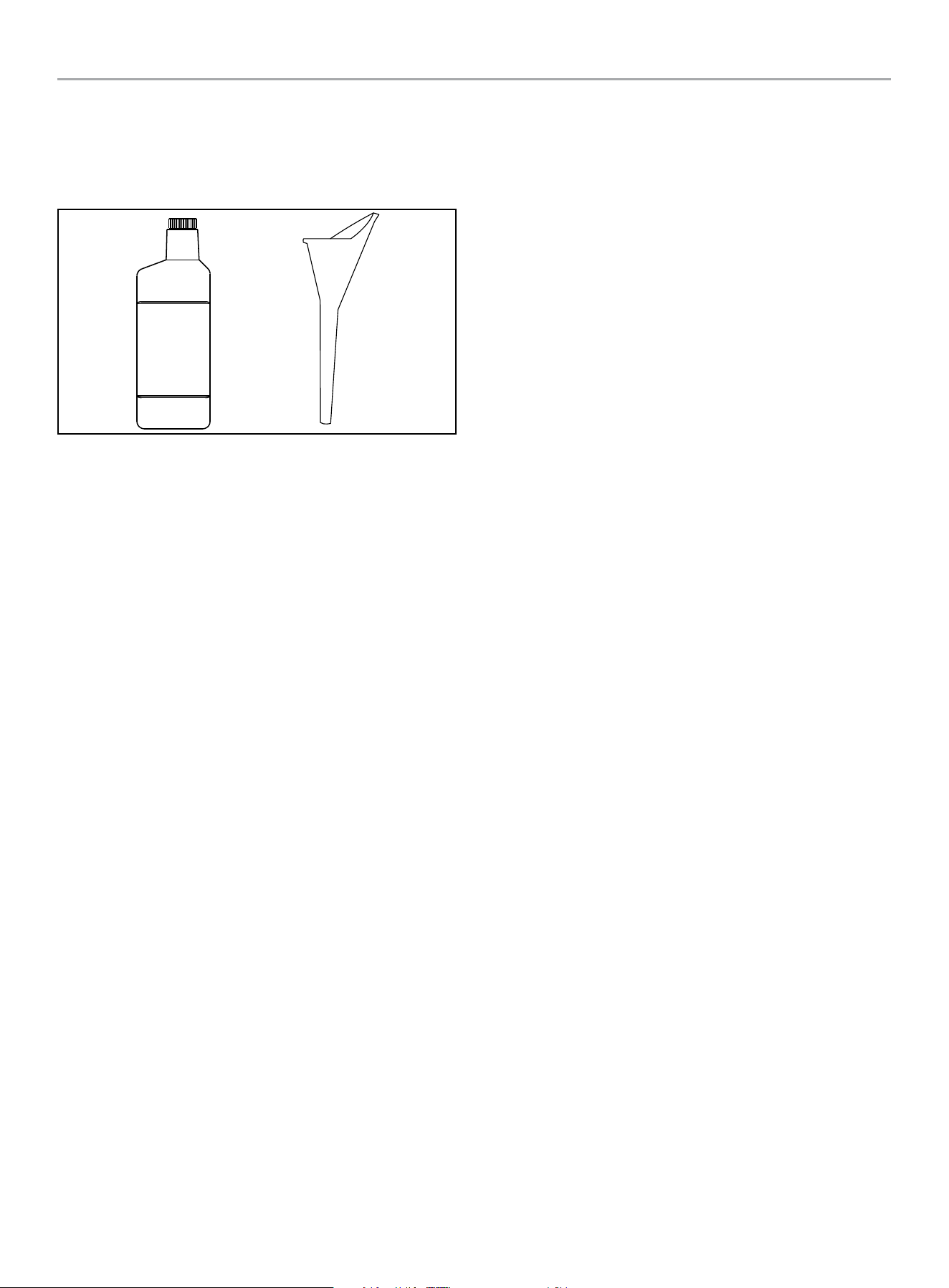
Engine Oil
..................................... 16.9 fl. oz. (500 ml)
Oil Funnel ...........................................................1
Tools Included
8–10 Wrench .......................................................1
12–14 Wrench ......................................................1
13–15 Wrench ......................................................1
Spark Plug Wrench (engine) .......................................1
Tools Needed
Needle Nose Pliers (for cotter pins)
201464 - REAR TINE TILLER
ASSEMBLY
16
ASSEMBLY
Your tiller requires some assembly. This unit ships from our factory
without oil. It must be properly serviced with fuel and oil before
operation.
If you have any questions regarding the assembly of your tiller, call
our Technical Support Team at 1-877-338-0999. Please have your
serial number and model number available.
Unpacking
1. Remove all parts and packaging components.
2. Remove top lid and remove sides.
3. Remove any remaining packaging.
4. With helper, remove the tiller from the shipping crate.
Attach Lower Handle
1. Loosen the lower handle bolts.
2. Align the lower handle holes to the middle height adjustment
holes in the transmission cover and install the (4) M10×25 mm
flange head bolts and (2) M10 nuts. Tighten all hardware.
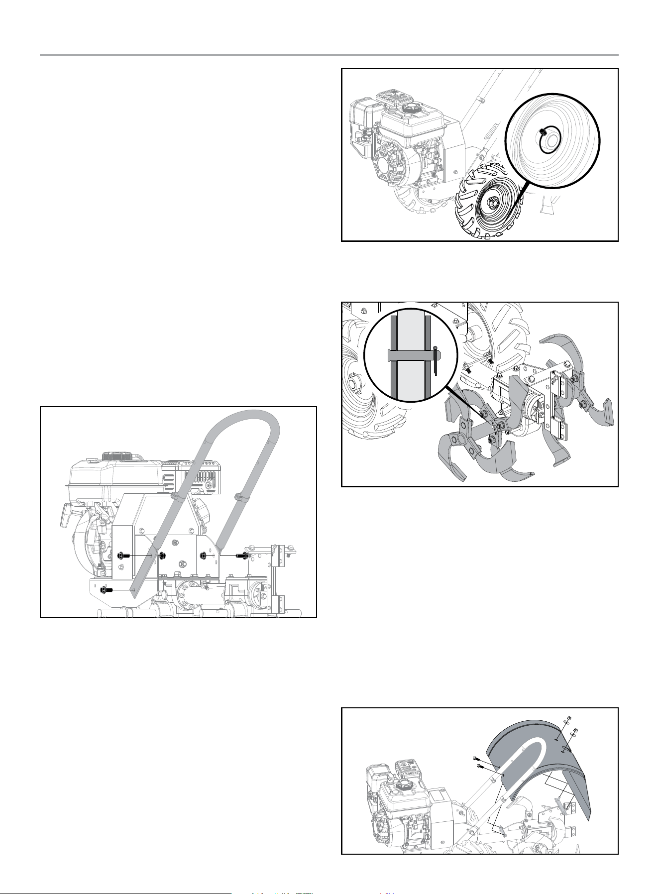
Install the Wheels
1. Remove the locking pins from the wheel hubs.
2. The tiller wheels are directional. For best performance install
the wheels with the tire thread facing the direction as shown.
3. Slide the wheel hub onto the wheel axle.
4. Align the wheel hub hole with the hole in the axle and insert
the locking pin.
5. Rotate the locking pin ring to lock the pin in position. Repeat
on other wheel.
Install the Tines
Before Assembly
1. Check the orientation of the tine blade. The sharp cutting
edge should be facing the direction of tine rotation for your
tiller.
2. Install the tine assemblies on each tine axle. Secure with (2)
pins and (2) cotter pins. Bend cotter pins once inserted to
prevent them from coming out.
Install the Tine Shield
1. Remove the (4) M8×20 mm flange head bolts and (2) washers
installed in the tine shield brackets above the transmission
housing.
2. Place the tine shield on the bracket and secure with the bolts
and washers removed in step 1.
201464 - REAR TINE TILLER
ASSEMBLY
17
Install the Depth Regulator
1. Remove the (1) pin and (1) clip from the depth regulator lever.
2. Insert the depth regulator into the bottom of the depth
regulator bracket.
3. Insert the pin through the bracket and lever.
4. Install the clip removed in 1 onto the depth regulator lever.
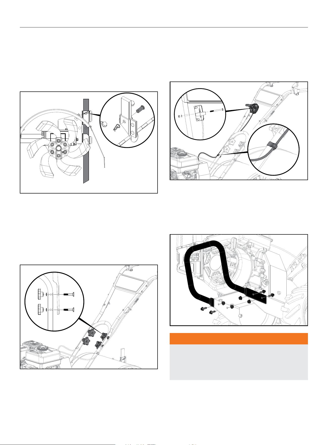
Attach Upper Handle
1. Slide the upper handle down over the lower handle and align
the holes.
2. Insert the (4) M8×50 curved head bolts into the holes as
shown and securely with the (4) handle knobs and (4) curved
Washer.
3. Tighten the handle knobs securely.
Attach Speed Control
1. Attach speed control using provided (1) M6 bolt, (1) washer,
and (1) M6 nut.
2. Tighten completely.
3. Use plastic clips to secure the cables as shown.
Attach Front Bumper
1. Slide the front bumper onto the outside of the base frame and
align the holes.
2. Install the (4) M8×20 mm bolts and (4) M8 lock nuts and
tighten securely.
WARNING
Before operating your machine, carefully read and understand
all safety, controls and operating instructions.
Failure to follow these instructions can result in serious
personal injury.
201464 - REAR TINE TILLER
ASSEMBLY
18
Introduction
This section describes the location and function of the controls on
your tiller. Refer to the following section, Operation, for detailed
operating instructions.
Practice using these controls, with the engine shut off, until you
understand the operation of the controls and feel confident with
each of them.
Wheel Drive Pins
Each wheel is equipped with a locking pin that secures the wheel
to the wheel shaft. The wheels can be positioned in either a
WHEEL DRIVE or a FREEWHEEL mode.
Before starting the engine, put both wheels in the WHEEL DRIVE
position by inserting the wheel drive pins through the wheel hubs
and axle shaft. Doing so “locks” the wheels to the axle shaft,
causing the wheels to turn when either the forward or reverse
lever is engaged.
Use the FREEWHEEL mode only when the engine is not running. In
FREEWHEEL, the wheel locking pins are placed only through the
holes in the wheel shaft (not the wheel hubs), thus allowing the
wheels to turn freely when you manually move the tiller
WARNING
Never allow either of the wheels to be in the FREEWHEEL
position when the engine is running. Always put both wheels in
the WHEEL DRIVE position before starting the engine.
Failure to comply could cause loss of tiller control, property
damage, or personal injury.
To replace the wheels in the WHEEL DRIVE or FREEWHEEL:
1. Stop the engine, disconnect the spark plug wire from the
spark plug and allow engine to cool.
2. Raise one wheel about 1 in. (2.5 cm) off the ground and place
a sturdy support under the transmission.
WARNING
Do not place tiller on its side when changing wheel drive
positions. Doing so could result in gasoline leaking from the
fuel tank.
Failure to follow this instruction could result in personal injury
or property damage.
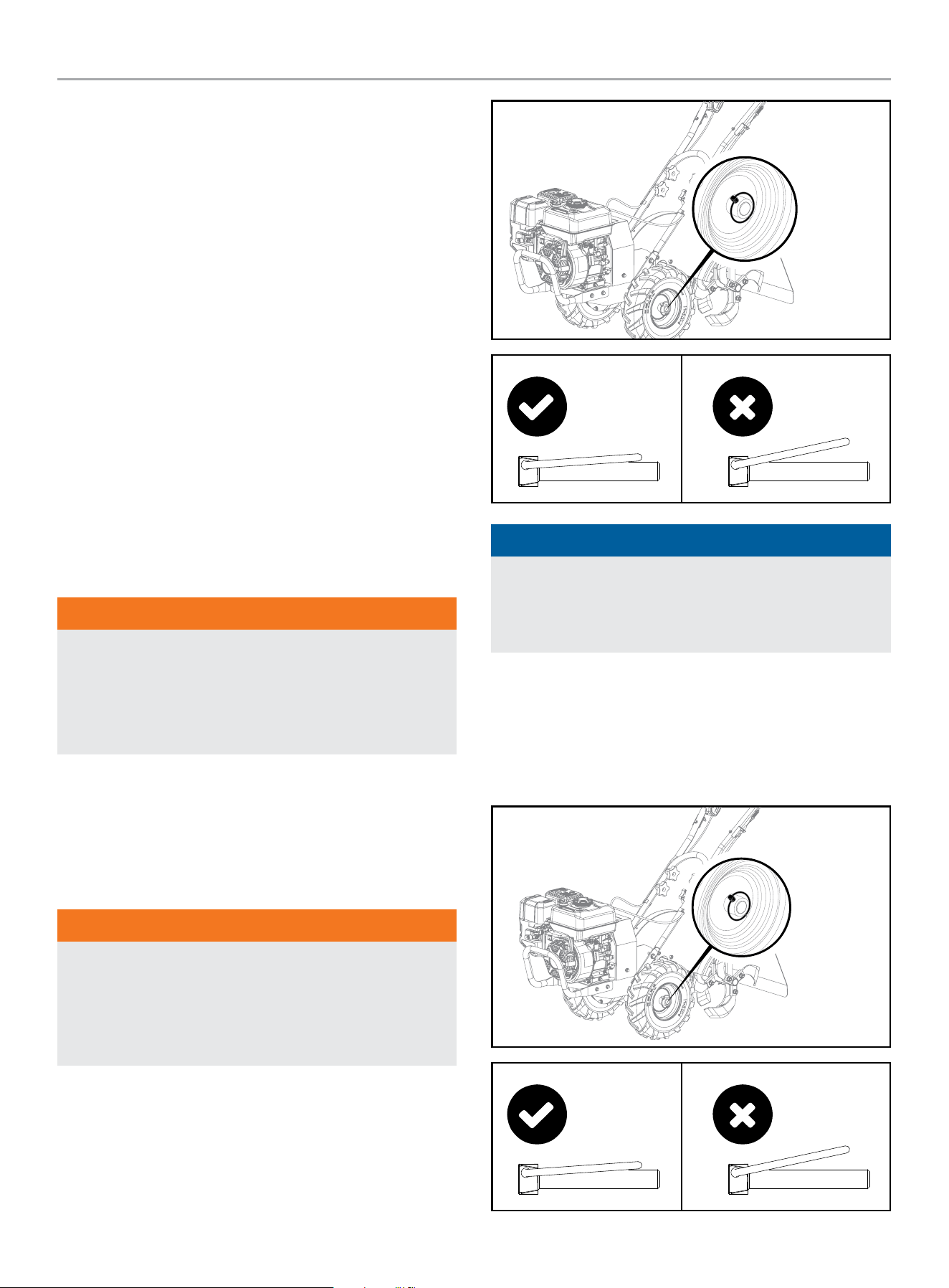
FOR WHEEL DRIVE MODE: Slide wheel outward and align the
holes. Insert locking pin through wheel hub and wheel shaft.
Secure wheel locking pin by pushing in as far as it will go then
wrapping ring around the wheel shaft as shown. Repeat with
the other wheel and then remove the support from beneath the
transmission.
WHEEL DRIVE Position
CORRECT PIN
ORIENTATION
INCORRECT PIN
ORIENTATION
NOTICE
Ensure that the ring on the wheel pin is folded over completely
against the pin. Failure to do so could cause the wheel pin to
fall out of the hole and the wheel to slide off of the axle during
use.
FOR FREEWHEEL MODE: Slide the wheel inward and insert the
wheel drive locking pin only through the hole in the axle shaft.
Secure wheel locking pin by pushing in as far as it will go then
wrapping ring around the wheel shaft as shown. Repeat for
the other wheel and then remove the support from beneath the
transmission.
FREEWHEEL Position
CORRECT PIN
ORIENTATION
INCORRECT PIN
ORIENTATION
201464 - REAR TINE TILLER
ASSEMBLY
19
NOTICE
Ensure that the ring on the wheel pin is folded over completely
against the pin. Failure to do so could cause the wheel pin to
fall out of the hole and the wheel to slide off of the axle during
use.
WARNING
Before starting engine, be sure that both wheels are in WHEEL
DRIVE position. See Wheel Drive Pins for instructions.
Engaging the Forward Lever when the wheels are not in
WHEEL DRIVE could allow the tines to rapidly propel the tiller
forward or backward. Failure to comply could cause loss of
tiller control, property damage, or personal injury
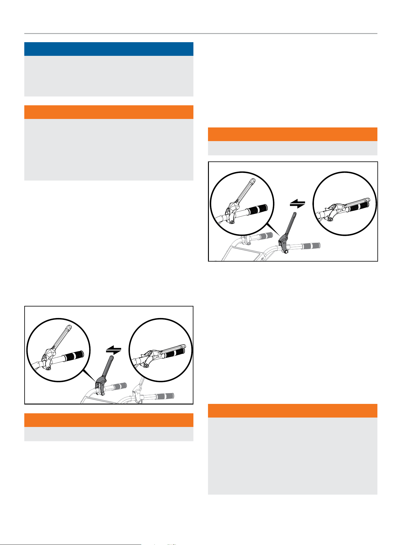
Forward Lever
The Forward Lever controls the engagement of forward drive to
the wheels and counter-rotating tilling with the tines.
To operate the Forward Lever:
1. Put wheels in WHEEL DRIVE position (see “WARNING”
statement).
2. Depress and hold the lever against the handlebar to start the
wheels going forward and tines rotating in a reverse direction.
3. Release the lever to disengage (stop) the wheels and tines
(the engine will continue to run).
WARNING
Never pull the tiller toward you with the tines engaged.
Reverse Lever
The reverse lever controls the reverse motion of the wheels
and forward motion of the tines. To operate the Reverse
Lever:
1. Put wheels in WHEEL DRIVE position (see “WARNING”
statement).
2. Ensure all tiller tine motion has stopped before re-engaging
tines.
3. Depress and hold the lever against the handlebar to start the
wheels in reverse and tines rotating in a forward direction.
4. Release the lever to disengage (stop) the wheels and tines
(the engine will continue to run).
WARNING
DO NOT till in reverse.
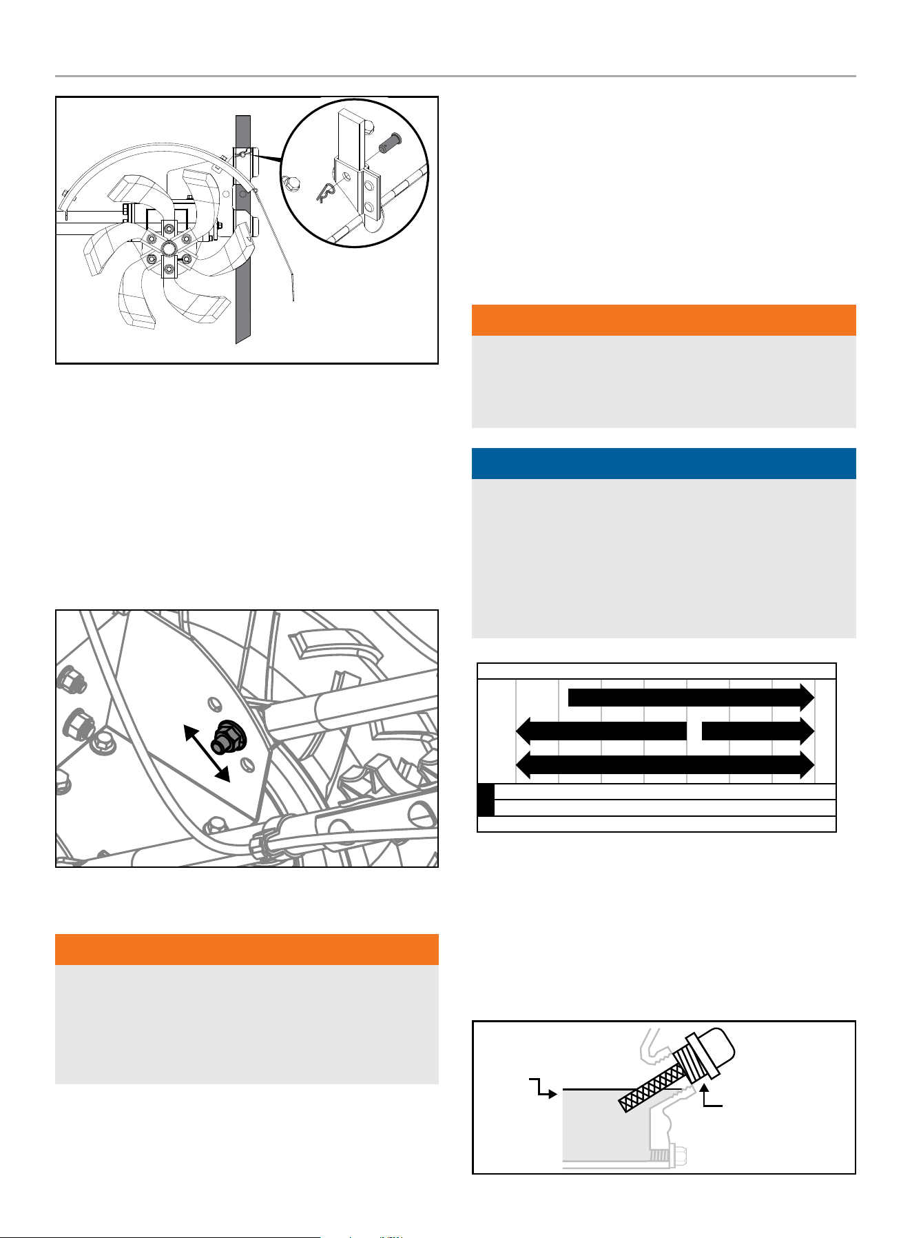
Depth Regulator Lever Adjustment
This regulator lever controls the tilling depth of the tines. Remove
pin and clip and slide regulator lever up or down as required.
Reassemble pin and clip.
The “travel position” (highest hole) raises the tines approximately
1-1/2 in. (4 cm) off the ground, allowing the tiller to be moved
without the tines contacting the ground. This setting should also
be used when starting the engine.
Moving the regulator lever upward will increase the tilling depth.
The lowest notch allows a tilling depth of approximately 6 in.
(15 cm), depending on soil conditions. For best results, always
begin tilling at a very shallow depth setting and gradually increase
the tilling depth.
WARNING
Do not attempt to till too deeply too quickly.
Gradually work down to deeper tilling depths.
Place the depth regulator lever in the “travel” position before
starting the engine. This position prevents the tines from
touching the ground until you are ready to begin tilling.
Failure to follow this warning could result in personal injury or
property damage.
201464 - REAR TINE TILLER
OPERATION
20
Handlebar Height Adjustment
The handlebar height is adjustable to three different settings. In
general, adjust the handlebars so they are at waist level when the
tines are 3-4 in. (8-10 cm) in the soil.
To adjust the handlebars:
1. Stop engine, disconnect spark plug wire from spark plug, and
allow engine to cool.
2. Remove hardware, reposition handlebars, and reinstall
hardware securely.
High
Low
OPERATION
WARNING
Before operating your machine, carefully read and understand
all safety, controls and operating instructions in this Operator’s
Manual.
Failure to follow these instructions can result in serious
personal injury
Introduction
Read this section before you start the engine. Then, take the time
to familiarize yourself with the basic operation of the tiller before
using it in the garden. Find an open, level area and practice using
the tiller controls without the tines engaging the soil (put tines in
“travel” setting). Only after you’ve become completely familiar
with the tiller should you begin using it in the garden.
Add Engine Oil
WARNING
DO NOT attempt to crank or start the engine before it has been
properly filled with the recommended type and amount of oil.
Damage to the engine as a result of failing to follow these
instructions will void your warranty.
NOTICE
The recommended oil type for typical use is 10W-30
automotive oil. However, using the listed conventional oils
shown in the “Recommended Engine Oil Type” chart may be
used for typical use including the first 5 hours of the break-in
run time period of the engine.
If running tiller in extreme temperatures, refer to the
“Recommended Engine Oil Type” chart.
-20 0 20 40 60
Ambient temperature
Recommended Engine Oil Type
80 100 120
-28.9
°F
°C
-17.8 -6.7 4.4 15.6 26.7 37. 8 48.9
10W-30
5W-30 Full Synthetic
10W-405W-30
1. Place tiller on a flat, level surface.
2. Put the wheels in the WHEEL DRIVE position.
3. Remove oil fill cap/dipstick to add engine oil.
4. Using a funnel, add up to 16.9 fl. oz. (500 ml) of oil and
replace oil fill cap/dipstick. DO NOT OVERFILL.
5. Check engine oil level and add as needed.
MAX
OIL DIP STICK
201464 - REAR TINE TILLER
OPERATION
21
NOTICE
Once oil has been added, a visual check should show oil about
1-2 threads from running out of the fill hole.
When using the dipstick to check oil level, DO NOT screw in
the dipstick while checking.
NOTICE
Check oil level often during the break-in period. Refer to the
Maintenance section for recommended service intervals.
CAUTION
This engine is equipped with a low oil shut-off and will stop
when the oil level in the crankcase falls below the threshold
level.
NOTICE
We consider the first 5 hours of run time to be the break-
in period for the engine. During the break in period we
recommend using standard automotive non-synthetic blended
oils. After the break in period synthetic lubricant can be used
but is not required. Adjusting throttle setting will increase/
decrease engine speed helping to seat piston rings. Avoid
bogging or lugging the engine down and avoid prolonged
running at constant RPM. After the 5 hour break-in period,
change the oil. Using synthetic lubricants does not increase
the recommended oil change interval.
NOTICE
Synthetic oil may be used after the 5 hour initial break-in
period. Using synthetic oil does not decrease the recommended
oil change interval. Full synthetic 5W-30 oil will aid in starting
in cold ambient < 41º F (5º C) temperatures.
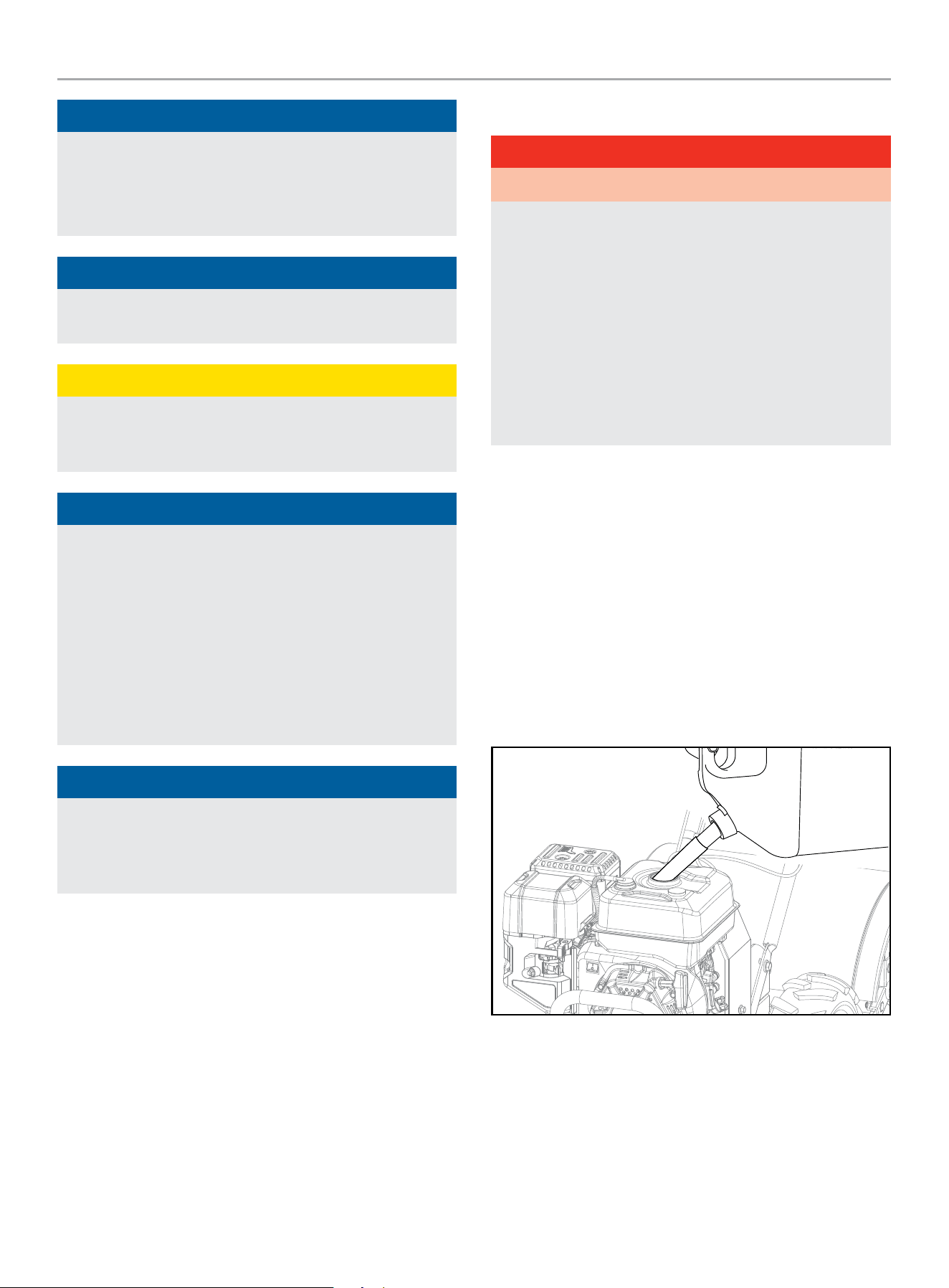
Add Fuel
DANGER
Gasoline vapors are highly flammable and extremely explosive.
DO NOT light or smoke cigarettes. Fire or explosion can cause
severe burns or death.
Only fill or drain fuel outdoors in a well-ventilated area. DO
NOT pump gasoline directly into the engine. Use an approved
container to transfer the fuel to the engine.
Never use a gasoline container, gasoline tank, or any other fuel
item that is broken, cut, torn or damaged.
DO NOT overfill the gasoline tank. Always keep fuel away from
sparks, open flames, pilot lights, heat and other sources of
ignition.
Use clean, fresh, regular unleaded gasoline with a minimum
octane rating of 87 and an ethanol content of 10% or less by
volume. ybc
DO NOT mix oil with gasoline.
1. Remove the gasoline cap.
2. Slowly add gasoline to the tank. DO NOT OVERFILL. Gasoline
can expand after filling. A minimum of ¼ in. (6.4 mm) of
space left in the tank is required for gasoline expansion
although more than ¼ in. (6.4 mm) is recommended. Gasoline
can be forced out of the tank as a result of expansion if
overfilled and can affect the stable running condition of the
tiller.
3. Screw on the gasoline cap and wipe away any spilled fuel.
201464 - REAR TINE TILLER
OPERATION
22
CAUTION
Use unleaded gasoline with a minimum octane rating of 87
and an ethanol content of 10% or less by volume.
DO NOT light cigarettes or smoke when filling the tank.
DO NOT mix oil and gasoline.
DO NOT overfill the tank. Fill tank to approximately ¼ in.
(6.4 mm) below the top of the tank to allow for gasoline
expansion.
DO NOT pump gasoline directly into the tiller at the pump. Use
an approved fuel container to transfer the gasoline to the tiller.
DO NOT fill tank indoors.
DO NOT fill tank when the engine is running or hot.
WARNING
Pouring gasoline too fast through the fuel screen may result in
gasoline splashing over the tiller and operator while filling.
NOTICE
The engine works well with 10% or less ethanol blended
gasoline. When using ethanol-gasoline blends there are some
issues worth noting:
– Ethanol-gasoline blends can absorb more water than
gasoline alone.
– These ethanol blends can eventually separate, leaving
water or a watery goo in the tank, fuel valve and
carburetor. The compromised gasoline can be drawn into
the carburetor and cause damage to the engine and/or
create potential hazards.
– If a fuel stabilizer is used, confirm that it is formulated to
work with ethanol-gasoline blends.
– Any damages or hazards caused by using ethanol blended
gasoline higher than 10% by volume, improperly stored
gasoline, and/or improperly formulated stabilizers, are not
covered by manufacturer’s warranty.
It is advisable to always shut off the gasoline supply and
run the engine to starvation after each use. See Storage
instructions for extended non-use.
NOTICE
In some State and local jurisdictions, operate power equipment
during reasonable hours to comply within local noise
ordinances. For more information, contact your State and local
government for specific requirements.
Transmission Gear Oil
The tiller ships from the factory with transmission gear oil
installed. Operating the tiller when the transmission is low on oil
can result in severe damage. See Transmission Gear Oil Service
for more details.
Starting the Engine
To help prevent serious personal injury or damage to equipment:
WARNING
Do not attempt to engage the tines or wheels until you have
read all of the operating instructions
WARNING
Before starting engine, put both wheels in the WHEEL DRIVE
position. Never have wheels in FREEWHEEL position when
engine is running. When the wheels are in FREEWHEEL, they
do not hold back the tiller and the tines could propel the tiller
rapidly forward or backward.
WARNING
Never run engine indoors or in enclosed, poorly ventilated
areas. Engine exhaust contains carbon monoxide, an odorless
and deadly gas.
WARNING
Keep away from rotating tines. Rotating tines will cause injury.
1. Make certain the tiller is on a flat, level surface. Tilling on a
grade greater than 15 degrees can be unsafe and cause a
low oil shut-off as oil pools in the engine opposite the low oil
sensor.
2. Put the wheels in the WHEEL DRIVE position (wheel pins must
be through holes in wheel hubs and wheel shaft).
3. Move the depth regulator lever all the way down to the
“travel” position, so that the tines clear the ground.
4. Release all controls on the tiller.
CHOKE
FAST
FUEL OFF
SLOW
RUN
FUEL ON
201464 - REAR TINE TILLER
OPERATION
23
5. Move the choke lever to the “CHOKE” position.
6. Move the fuel valve to the “ON” position.
CHOKE
FUEL VALVE
7. Move the throttle lever to the “FAST” position.
8. Pull the starter cord slowly until resistance is felt and then
pull rapidly.
9. As engine warms up, move the choke lever to the “RUN”
position.
NOTICE
If the engine starts but does not run, make certain that the
tiller is on a flat, level surface. The engine is equipped with a
low oil sensor that will prevent the engine from running when
the oil level falls below a critical threshold.
Stopping the Engine and the Tiller
In an emergency, turn the engine switch to the “OFF”
position.
Under normal operation:
1. To stop the wheels and tines, release all control levers.
2. Turn the fuel valve to the “OFF” position.
FUEL OFF
FUEL ON

201464 - REAR TINE TILLER
TILLING TIPS AND TECHNIQUES
24
3. Let the engine run until fuel starvation has stopped the
engine. This usually takes a few minutes.
Operation at High Altitude
The density of air at high altitude is lower than at sea level. Engine
power is reduced as the air mass and air-fuel ratio decrease.
Engine power will be reduced approximately 3½% for every 1000
ft. of elevation above sea level. This is a natural trend and cannot
be changed by adjusting the engine. At high altitudes increased
exhaust emissions can also result due to the increased enrichment
of the air fuel ratio. Other high altitude issues can include hard
starting, increased fuel consumption and spark plug fouling.
To alleviate high altitude issues other than the natural power
loss, CPE can provide a high altitude carburetor main jet. The
alternative main jet and installation instructions can be obtained
by contacting our Technical Support Team. Installation instructions
are also available in the Technical Bulletin area of the CPE website.
The part number and recommended minimum altitude for the
application of the high altitude carburetor main jet is listed in the
table below.
In order to select the correct high altitude main jet it is necessary
to identify the carburetor model. For this purpose, a code is
stamped on the side of the carburetor. Select the correct high
altitude jet part number corresponding to the carburetor code
found on your particular carburetor.
Carb. Code High Alt. Jet Part Number Min. Altitude
100732679
-0001
100092470
3281-9843 ft.
(1000-3000 m)
WARNING
Operation using the alternative main jet at elevations lower
than the recommended minimum altitude can damage the
engine. For operation at lower elevations, the originally
supplied standard main jet must be used. Operating the
engine with the wrong engine configuration at a given altitude
may increase its emissions and decrease fuel efficiency and
performance.
TILLING TIPS AND TECHNIQUES
Tilling Depths
WARNING
Before tilling, contact your telephone or utilities company and
inquire if underground equipment or lines are used on your
property. Do not till near buried electric cables, telephone
lines, pipes or hoses.
Avoid pushing down on the handlebars in an attempt to force the
tiller to dig deeper. Doing so takes the weight off the powered
wheels, causing them to lose traction. Without the wheels
helping to hold the tiller back, the tines will attempt to propel the
tiller – often causing the tiller to skip rapidly across the ground.
(Sometimes, slight downward pressure on the handlebars will
help get through a particularly tough section of sod or unbroken
ground, but in most cases this wont be necessary.)
Avoid trying to dig too deeply too quickly, especially when busting
sod or when tilling soil that hasn’t been tilled for some time. Use
shallow depth regulator settings (only an inch or two deep) for
the first passes through the soil. With each succeeding pass, dig
another inch or two deeper. (Watering the area a few days prior to
tilling will make the tilling easier, as will letting the newly worked
soil set for a day or two before making a final, deep tilling pass.
When cultivating (breaking up surface soil around plants to
destroy weeds), adjust the tines to dig only 1 in. to 2 in. (2.5 to
5 cm) deep. Using shallow tilling depths helps prevent injury to
plants whose roots often grow close to the surface. If needed, lift
up on the handlebars slightly to prevent the tines from digging too
deeply. (Cultivating on a regular basis not only eliminates weeds,
it also loosens and aerates the soil for better moisture absorption
and faster plant growth.)
Choosing Correct Wheel and Tine Speeds
With experience, you will find the “just right” tilling depth and
tilling speed combination that is best for your garden.
Set the engine throttle lever at a speed to give the engine
adequate power and yet allow it to operate at the slowest possible
speed; at least until you have achieved the maximum tilling depth
you desire. Faster engine speeds may be desirable when making
final passes through the seedbed or when cultivating. Selection of
the correct engine speed, in relation to the tilling depth, will ensure
a sufficient power level to do the job without causing the engine to
labor.
Let the Tiller Do the Work
While tilling, relax and let the wheels pull the tiller along while the
tines do the digging. Walk on the side that is not yet finished (to
avoid making footprints in the freshly tilled soil) and lightly, but
securely grip the handlebar with just one hand.
Avoid Tilling Soggy, Wet Soil
Tilling wet soil often results in large, hard clumps of soil that can
interfere with planting. If time permits, wait a day or two after
heavy rains to allow the soil to dry before tilling. Test soil by
squeezing it into a ball. If it compresses too easily, it is too wet to
till.

201464 - REAR TINE TILLER
TILLING TIPS AND TECHNIQUES
25
Preparing Seedbeds
When preparing a seedbed, go over the same path twice in the
first row, then overlap one-half the tiller width on the rest of the
passes. When finished in one direction, make a second pass at
a right angle. Overlap each pass for best results (in very hard
ground, it may take three or four passes to thoroughly pulverize
the soil.)
If the garden size will not permit lengthwise and then crosswise
tilling, then overlap the first passes by one-half a tiller width,
followed by successive passes at one quarter width.
Cultivating
With planning, you can allow enough room between rows to
cultivate. Leave room for the hood width, plus enough extra room
for future plant growth.
Tilling on Slopes
Read the following recommendations before tilling on slopes:
If you must garden on a moderate slope, please follow two very
important guidelines:
1. Till only on moderate slopes, never on steep ground where
footing is difficult. Tilling on a grade greater than 15 degrees
can be unsafe and cause a low oil shut-off as oil pools in the
engine opposite the low oil sensor.
2. We recommend tilling up and down slopes rather than
terracing. Tilling vertically on a slope allows maximum
planting area and also leaves room for cultivating.
IMPORTANT: When tilling on slopes, be sure the correct oil
level is maintained in the engine (check every one-half hour of
operation). The incline of the slope will cause the oil to slant away
from its normal level and this can starve engine parts of required
lubrication. Keep the engine oil level at the full point at all times!
WARNING
Do not operate tiller on a slope too steep for safe operation. Till
slowly and be sure you have good footing. Never permit tiller
to freewheel down slopes. Failure to follow this warning could
result in personal injury.
Tilling on slopes greater than 15 degrees can be unsafe and
cause a low oil shut-off due to oil pooling in the opposite side
of the engine to the low oil sensor.
Tilling Up and Down Slopes (Vertical Tilling)
To keep soil erosion to a minimum, be sure to add enough organic
matter to the soil so that it has good moisture-holding texture and
try to avoid leaving footprints or wheel marks.
When tilling vertically, try to make the first pass uphill as the tiller
digs more deeply going uphill than it does downhill. In soft soil or
weeds, you may have to lift the handlebars slightly while going
uphill. When going downhill, overlap the first pass by about one-
half the width of the tiller.
Tilling Across Slopes Without Using Terraces (Horizontal
Tilling)
If vertical or terracing gardening aren’t practical for you, then you
can till laterally across a slope. We don’t recommend this method
as it can create unsure footing and invites soil erosion.
As in terrace gardening, start at the top of the slope and overlap
the first pass by half the width of the tiller. For added stability of
the tiller, always keep the uphill wheel in the soft, newly tilled soil.
Terrace Gardening
– When a slope is too steep or too short for vertical tilling, it may
be necessary to till across the slope and create terraced rows.
Terraces are rows that are cut into the side of a slope, creating
a narrow, but flat area on which to plant.
– On a long slope, you can make several terraces, one below the
other.
– Terraces should be only 2-to-3 ft. (60-90 cm) wide. Digging
too far into the side of the slope will expose poor subsoil that is
unproductive for plants.
– To create a terrace, start at the top of the slope and work
down. Go back and forth across the first row.
– Each succeeding lower terrace is started by walking below
the terrace you’re preparing. For added stability of the tiller,
always keep the uphill wheel in the soft, newly tilled soil.
Do not till the last 12 in. (30 cm) or more of the downhill
outside edge of each terrace. This untilled strip helps prevents
the terraces from breaking apart and washing downhill. It also
provides a walking path between rows.
Clearing the Tines
The tines have a self-clearing action which eliminates most
tangling of debris in the tines. However, occasionally dry grass,
stringy stalks or tough vines may become tangled. Follow these
procedures to help avoid tangling and to clean the tines, if
necessary.
– To reduce tangling, set the depth regulator deep enough to get
maximum “chopping” action as the tines chop the material
against the ground. Also, try to till under crop residues or cover
crops while they are green, moist and tender.

201464 - REAR TINE TILLER
MAINTENANCE
26
– While power composting, try swaying the handlebars from side
to side about 6 in. to 12 in. (15 to 30 cm). This “fishtailing”
action often clears the tines of debris.
– If tangling occurs, lift the tines out of the soil and run the tiller
in reverse (if unit is equipped with powered reverse) for a
few feet. This reversing action should unwind a good deal of
debris.
– It may be necessary to remove the debris by hand (a pocket
knife will help you to cut away the material). Be sure to stop
the engine and disconnect the spark plug wire before clearing
the tines by hand.
WARNING
Before clearing the tines by hand, stop the engine, allow all
moving parts to stop and disconnect the spark plug wire.
Failure to follow this warning could result in personal injury.
Loading and Unloading the Tiller
WARNING
Loading and unloading the tiller into a vehicle is potentially
hazardous and we don’t recommend doing so unless
absolutely necessary, as this could result in personal injury
or property damage. However, if you must load or unload the
tiller, follow the guidelines given next.
– Before loading or unloading, stop the engine, wait for all parts
to stop moving, disconnect the spark plug wire and let the
engine and muffler cool.
– The tiller is too heavy and bulky to lift safely by one person.
Two or more people should share the load.
– Use sturdy ramps and manually (engine shut off) roll the tiller
into and out of the vehicle. Two or more people are needed to
do this.
– The ramps must be strong enough to support the combined
weight of the tiller and any handlers. The ramps should provide
good traction to prevent slipping; they should have side rails
to guide the tiller along the ramps; and they should have a
locking device to secure them to the vehicle.
– The handlers should wear sturdy footwear that will help to
prevent slipping.
– Position the loading vehicle so that the ramp angle is as flat
as possible (the less incline to the ramp, the better). Turn the
vehicle’s engine off and apply its parking brake.
– When going up ramps, stand in the normal operating position
and push the tiller ahead of you. Have a person at each side to
turn the wheels.
– When going down ramps, walk backward with the tiller
following you. Keep alert for any obstacles behind you. Position
a person at each wheel to control the speed of the tiller. Never
go down ramps tiller-first, as the tiller could tip forward.
– Place wooden blocks on the downhill side of the wheels if you
need to stop the tiller from rolling down the ramp. Also, use
the blocks to temporarily keep the tiller in place on the ramps
(if necessary), and to chock the wheels in place after the tiller
is in the vehicle.
– After loading the tiller, prevent it from rolling by engaging the
wheels in the WHEEL DRIVE position. Chock the wheels with
blocks and securely tie the tiller down.
MAINTENANCE
WARNING
Before inspecting, cleaning or servicing the machine, shut off
engine, wait for all moving parts to come to a complete stop,
disconnect spark plug wire and move wire away from spark
plug. Remove ignition key on electric start models.
Failure to follow these instructions can result in serious
personal injury or property damage.
BEFORE EACH USE
Check engine oil level
Clean engine
Check air filter element
Check reduction gear oil
FIRST 2 HOURS OF BREAK-IN OPERATION
Check drive belt tension
Check nuts and bolts
Change engine oil
EVERY 5 OPERATING HOURS
Check engine oil level
EVERY 10 OPERATING HOURS
Check drive belt tension
Check nuts and bolts
Change engine oil
Lubricate tiller

201464 - REAR TINE TILLER
MAINTENANCE
27
AFTER THE FIRST MONTH OR FIRST 20 HOURS
Change engine oil
Replace reduction gear oil
Clean air filter element
EVERY 30 OPERATING HOURS
Check gear oil level in transmission
Check tines for wear
Check air pressure in tires
EVERY 3 MONTHS OR EVERY 50 HOURS OF OPERATION
Change engine oil
Replace reduction gear oil
Replace air filter element
Clean spark arrester
EVERY YEAR OR EVERY 100 HOURS OF OPERATION
Clean deposit cup
Check/adjust spark arrester*
Check/adjust idling
Check/adjust valve clearance**
Clean fuel tank and fuel filter**
EVERY TWO YEARS
Check fuel line
EVERY 125 HOURS
Clean up carbon from cylinder head piston**
NOTICE
– Change the engine oil after the first 2 hours of break-in
operation.
– Change the engine oil more frequently in dusty conditions.
* These items should be replaced if replacement needed.
* *These items should be maintained and repaired by our authorized dealer, unless
the owner has appropriate tools and is proficient with mechanical maintenance.
Tiller Lubrication
After every 10 operating hours, oil or grease the lubrication points
as described below.
Use clean lubricating oil (#30 weight engine oil is suitable) and
clean general purpose grease (grease containing a metal lubricant
is preferred, if available).
– Remove the wheels, clean the wheel shaft and apply a thin
coating of grease to the wheel shaft.
– Grease the back, front and sides of the depth regulator lever.
– Remove the tines and clean the tine shaft. Use a file or
sandpaper to gently remove any rust, burrs or rough spots
(especially around holes in shaft). Apply grease to ends of
shaft before installing tines.
– Oil the threads on the handlebar height adjustment screws and
the handlebar attaching screws.
Check for Oil Leaks
Before each use, check the tiller for signs of an oil leak — usually
a dirty, oily accumulation either on the unit or on the floor.
A little seepage around a cover or an oil seal is usually not a cause
for alarm. However, if the oil drips overnight, then immediate
attention is needed. Ignoring an oil leak can result in severe
transmission damage!
If a cover is leaking, check for loose screws. If the screws are
tight, a new gasket or oil seal may be required.
If the leak is from around a shaft and oil seal, the oil seal probably
needs to be replaced. See your authorized dealer or contact the
factory for service or advice.
IMPORTANT: Never operate the tiller if the transmission is low
on oil. Check the oil level after every 30 hours of operation and
whenever there is any oil leakage.
Check Hardware
Check for loose or missing hardware after every 10 operating
hours and tighten or replace (as needed) before reusing tiller.
Be sure to check the screws underneath the tiller hood that
secure the transmission cover and the depth regulator lever to the
transmission.
Check Tire Pressure
Check the air pressure in both tires. The air pressure should not
be more than 30 PSI (pounds per square inch).
Keep both tires equally inflated to help prevent machine from
pulling to one side.
201464 - REAR TINE TILLER
MAINTENANCE
28
Transmission Gear Oil Service
Check the transmission gear oil level after every 30 hours of
operation or whenever you notice any oil leak. Operating the tiller
when the transmission is low on oil can result in severe damage.
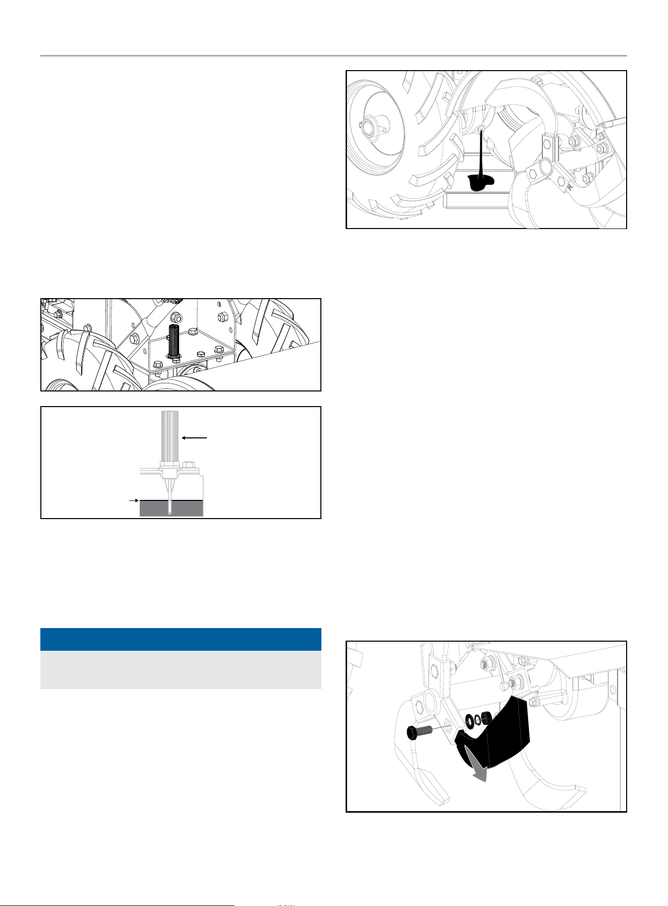
A. To Check the Transmission Gear Oil Level:
1. Check the gear oil level when the transmission is cool. Gear
oil will expand in warm operating temperatures and this
expansion will provide an incorrect oil level reading.
2. With the tiller on level ground, pull the depth regulator lever
all the way up.
3. Remove the dipstick/oil fill plug from the transmission
housing and look inside the oil fill hole to locate the main
drive shaft situated below the hole.
MAX
DIPSTICK
4. The gear oil level is correct if it falls between the two nodes
on the oil dipstick.
5. If the gear oil level is low, add GL-4 gear oil (SAE 85W-140 or
SAE 140).
6. If the gear oil level is okay, securely replace the oil fill plug.
NOTICE
Do not operate the tiller if the gear oil level is low. Doing so will
result in severe damage to the transmission components.
B. To Drain the Transmission Gear Oil:
The transmission gear oil does not need to be changed unless it
has been contaminated with dirt, sand or metal particles.
1. Drain gasoline from the fuel tank or run the engine until the
fuel tank is empty.
2. Drain the oil from the engine.
3. Remove the drain bolt from the bottom of the transmission
and allow the gear oil to drain completely.
4. Reinstall the drain bolt.
5. Refill the transmission using GL-4 gear oil (SAE 85W-140 or
SAE 140).
6. Refill the engine with engine oil and replenish the fuel tank
with gasoline.
Tines
The tines will wear with use and should be inspected at the
beginning of each tilling season and after every 30 operating
hours. The tines can be replaced either individually or as a
complete set. Refer to the parts list for tine identification and part
numbers.
A. Tine Inspection:
With use, the tines will become shorter, narrower and pointed.
Badly worn tines will result in a loss of tilling depth, and reduced
effectiveness when chopping up and turning under organic matter.
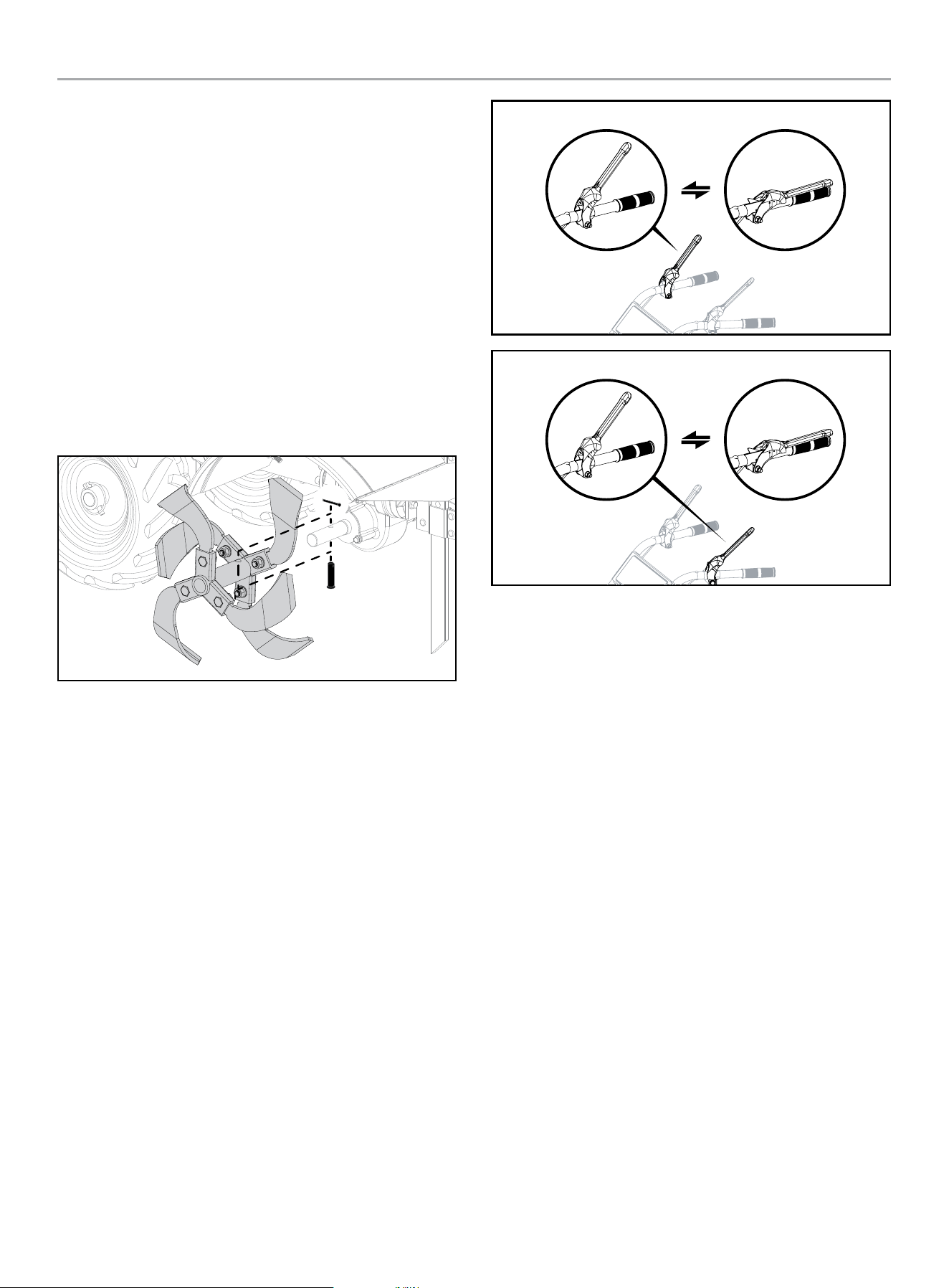
B. Removing/Installing a Single Tine:
1. With the engine shut off and the spark plug wire
disconnected, remove the M10×25 bolt, lock washer, flat
washer and M10 nut that attach a single tine to a tine holder.
If needed, use penetrating oil on the nuts.
2. When installing a single tine, be sure to position it so that its
cutting edge (sharp) will enter the soil first as the tiller moves
forward. Hand tighten completely.
201464 - REAR TINE TILLER
MAINTENANCE
29
C. Removing/Installing a Tine Assembly:
1. A tine assembly consists of eight tines mounted on a tine
holder.
2. If removing both tine assemblies, mark them “left” and
“right” before removal. Remove (2) pins and (2) cotter pins
that secure the tine assembly to the tine shaft. If necessary,
use a rubber mallet to tap the tine assembly outward off the
shaft.
3. Before reinstalling the tine assembly, inspect the tine shaft
for rust, rough spots or burrs. Lightly file or sand, as needed.
Apply a thin coat of grease to the shaft.
4. Install each tine assembly so that the cutting (sharp) edge of
the tines will enter the soil first when the tiller moves forward.
5. Bend cotter pins once inserted to prevent the pins from
coming out.
Checking and Adjusting Forward Drive Belt
Tension
It is important to maintain correct tension on the forward drive
belt. A loose belt will cause the tines and wheels to slow down
— or stop completely — even though the engine is running at full
speed. A too-tight belt can result in unintentional tine movement
when the lever is in the Neutral (released) position.
– Check belt tension after the first two hours of break-in
operation and after every 10 operating hours.
– At the end of each tilling season, check the belt for cracks,
cuts or frayed edges, and replace it as soon as possible.
To Check Belt Tension:
1. Stop engine, wait for all parts to stop moving and disconnect
spark plug wire.
2. With the forward and reverse lever in an open (released)
position, measure and note the overall length of the cable
spring by measuring from the outermost coil to the outermost
coil.
FORWARD LEVER
REVERSE LEVER
3. Squeeze the forward lever against the handlebar and re-
measure the length of the coils. The belt tension is correct if
this second measurement is between 1/6 in. to 3/16 in.
(2-5 mm) shorter than the first measurement.
4. If the spring is too short (less than 1/16 in. [2 mm]), the
tension is too tight. If the spring is too long (more than
3/16 in. [5 mm]), the tension is too loose.
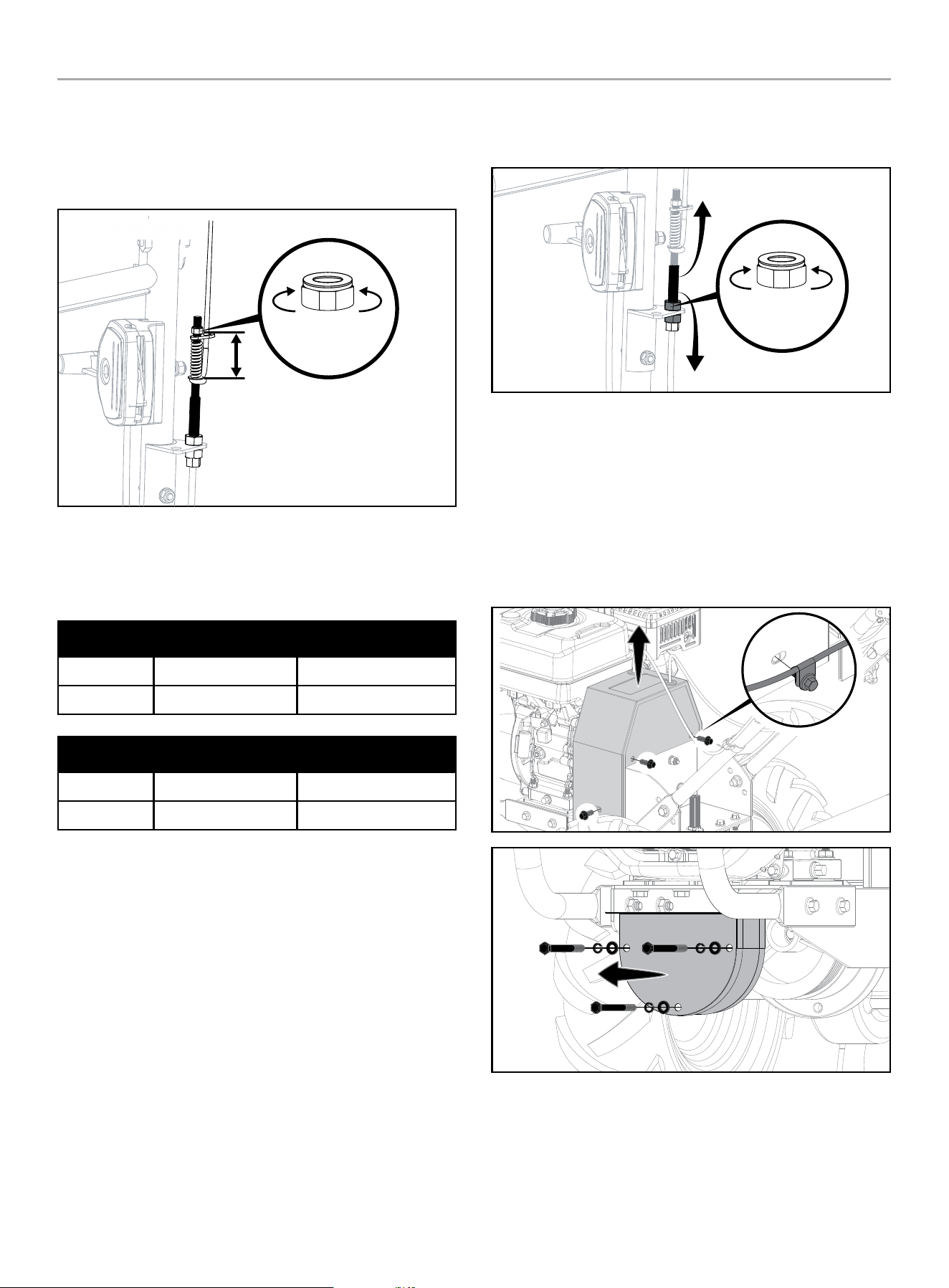
5. To adjust the length of the spring.
1. Release the forward lever.
2. Un-thread the hex nut halfway up the adjustment screw.
3. Unhook the top of the spring from the lever.
4. Use pliers to prevent the adjuster from turning and turn
the slotted screw located inside the spring clockwise
(viewed from operator’s position) to increase tension on
the spring. Turn the screw counter-clockwise to decrease
tension. Once adjusted, reattach the spring to the lever.
201464 - REAR TINE TILLER
MAINTENANCE
30
5. Repeat Steps 2 and 3 to re-measure the length of the
spring. When the second measurement is between
1/16 in. to 3/16 in. (2 to 5 mm) shorter than the first
measurement, re-tighten the hex nut against the top of
the adjuster.
DECREASE
TENSION
INCREASE
TENSION
OPEN LENGTH - CLOSED LENGTH = 1/6 to 3/16 in. (2 to 5 mm)
SPRING ADJUSTMENT
Replacement Belt Information
If the drive belt needs to be replaced, refer to the parts list for
information. The procedure requires average mechanical ability
and commonly available tools to change or replace.
LENGTH (inches) WIDTH (inches)
7PK612 24 in. ± 0.24 in. 0.95 in. ± 0.01 in.
5PK730 29 in. ± 0.20 in. 0.70 in. ± 0.02 in.
LENGTH (mm) WIDTH (mm)
7PK612 612.0 ± 6.0 mm 24.20 ± 0.30 mm
5PK730 730.0 ± 5.0 mm 17.80 ± 0.50 mm
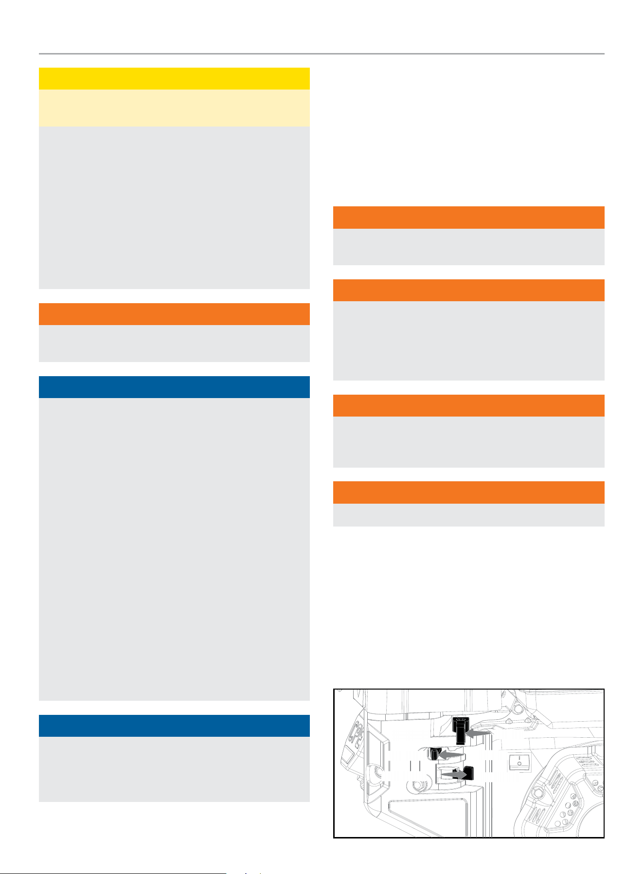
Belt Tension Adjustment
Proper belt tension is critical to good performance. After 1/2 hour
of operation, all cables may have to be adjusted due to initial
stretch. Thereafter, check tension after every 2 hours of operation.
To increase belt tension:
1. Turn jam nut clockwise in 1/8 in. (3 mm) increments.
2. Check adjustment.
To decrease belt tension:
1. Turn jam nut counter-clockwise in 1/8 in. (3 mm) increments.
2. Check adjustment.
3. This procedure can be repeated until conduit adjustment bolts
are fully adjusted. If no more adjustment can be made, belt
may have to be replaced.
DECREASE
TENSION
INCREASE
TENSION
Change Forward/Reverse Belts
1. Turn off engine. Engine must cool completely before
proceeding.
2. Remove spark plug wire and secure away from spark plug.
3. Reduce the belt tension by loosening the forward and reverse
cable lower jam nut.
4. Remove the upper and lower belt guards.
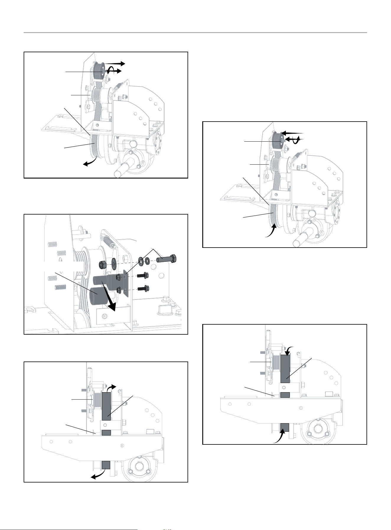
5. To remove the reverse drive belt:
a. Remove the reverse belt idler.
b. Slide the belt free of the reverse belt guides and engine
pulley.
201464 - REAR TINE TILLER
MAINTENANCE
31
c. Pull belt down and away from the transmission pulley.
REVERSE BELT
IDLER
ENGINE
PULLEY
REVERSE
BELT
TRANSMISSION
PULLEY
6. To remove the forward drive belt:
a. Remove the two forward belt guide studs and forward
belt idler assembly.
FORWARD BELT IDLER
FORWARD STUD
ASSEMBLY
b. Slide the belt free of the engine pulley.
c. Pull the belt down and away from the transmission pulley.
FORWARD
BELT
ENGINE
PULLEY
TRANSMISSION
PULLEY
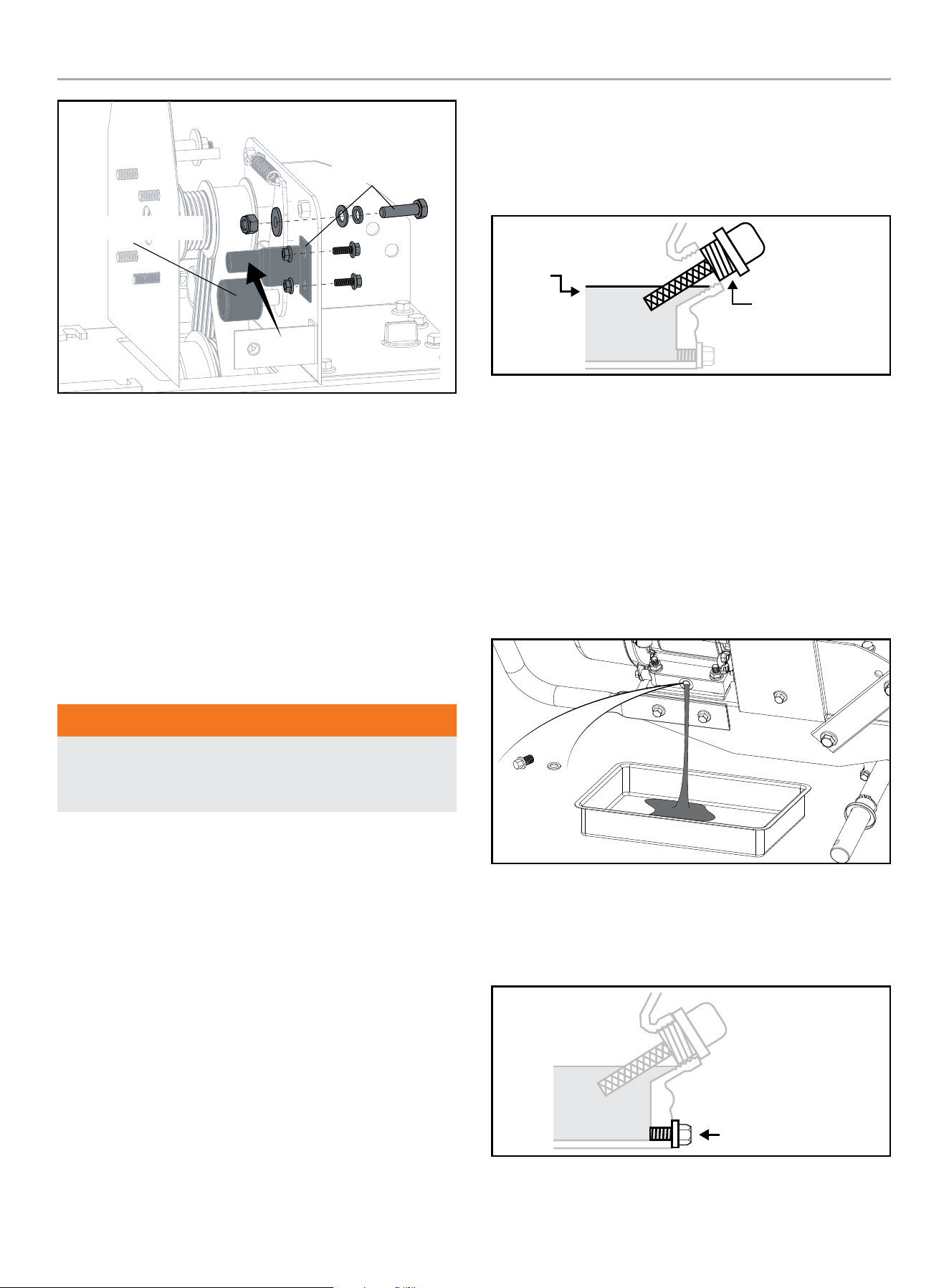
7. To install the reverse drive belt:
a. Insert the belt from underneath the unit and up around
the reverse belt idler.
b. Place the lower loop of the belt around the rear portion of
the transmission pulley.
c. Replace the reverse belt idler into the reverse belt idler
bracket. The belt should not go around the engine pulley.
Be sure the belt is inside of the reverse belt guide studs.
REVERSE BELT
IDLER
ENGINE
PULLEY
REVERSE
BELT
TRANSMISSION
PULLEY
8. To install the forward drive belt:
a. Insert the belt from underneath the unit and up around
the rearward portion on the engine pulley.
b. Place the lower loop of the belt around the rearward
portion of the transmission pulley.
c. Replace the forward belt guide studs and forward belt
idler assembly.
FORWARD
BELT
ENGINE
PULLEY
TRANSMISSION
PULLEY
201464 - REAR TINE TILLER
MAINTENANCE
32
FORWARD BELT IDLER
FORWARD STUD
ASSEMBLY
9. Tighten the forward and reverse lower jam nut.
10. Check the belt tension. The belts should be loose with the
drive levers disengaged.
11. Replace the upper and lower belt guards.
12. Re-attach the spark plug wire to the spark plug.
13. Follow Operating Instructions – start the engine and operate
the forward drive lever to check for proper cable adjustment
and belt tension. See the Belt Tension Adjustment section if
cable adjustment is required.
14. Start the engine and operate the reverse drive lever to check
for proper cable adjustment and belt tension. See the Belt
Tension Adjustment section if cable adjustment is required.
WARNING
The tines or wheels should not rotate with the engine running,
the depth regulator set at transport height (lowest height) and
the drive lever not engaged.
Engine Oil Service
Check the engine oil level before each use and after every five
hours of continuous operation. Running the engine when it is low
on oil will quickly ruin the engine.
It is recommended that you change the engine oil after every 10
hours of operation and even sooner when operating in extremely
dirty or dusty conditions.
A. To Check the Engine Oil Level:
1. Park the tiller on a level area and shut off the engine.
2. Level the engine (use the depth regulator lever to adjust the
engine angle).
3. Clean around the oil dipstick to prevent dirt from falling into
the crankcase.
4. On engines with a dipstick, remove it and wipe it clean.
Reinsert the dipstick, tighten it securely, and remove it. Add
oil as needed to bring the level up to the FULL mark. Wipe
dipstick clean each time oil level is checked. Do not overfill.
Tighten dipstick securely.
MAX
OIL DIP STICK
B. To Change the Engine Oil:
1. Place tiller on a flat, level surface.
2. Put the wheels in the WHEEL DRIVE position.
3. Remove the left-side wheel and carefully prop up until ready
to drain the engine oil.
4. Tilt the left-side wheel shaft into a drain pan.
5. Clean around the oil drain plug to prevent dirt from falling into
the crankcase. Remove oil drain plug.
6. Allow the engine oil to drain.
7. Replace oil drain bolt.
8. Reinstall the wheel.
9. Refill the with engine oil through the dipstick with funnel and
replenish the fuel tank with gasoline.
DRAIN BOLT
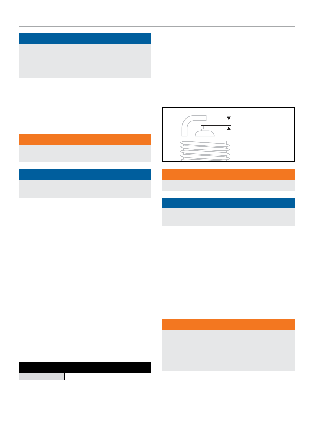
201464 - REAR TINE TILLER
STORAGE
33
NOTICE
Once oil has been added, a visual check should show oil about
1-2 threads from running out of the fill hole.
If using the dipstick to check oil level, DO NOT screw in the
dipstick while checking.
Air Cleaner Maintenance
A dirty air cleaner can restrict air flowing into the carburetor. To
keep the carburetor in good working conditions, please service the
air cleaner periodically. If operating the engine in extremely dusty
area, servicing should be done more often.
WARNING
Never clean the air cleaner element with gasoline or low flash-
point detergents, an explosion may happen.
NOTICE
Never run the engine without an air cleaner. Dirty air entering
the engine can speed up engine wear.
1. Remove the air cleaner cover and take the element out.
2. Soak in clean engine oil until saturated. Squeeze out excess
oil; otherwise, the engine will smoke when starting.
3. Clean the air cleaner cover and inner surface with a damp
cloth, be careful not to allow dust to enter the carburetor.
4. Reinstall the element and reinstall the air cleaner cover.
Spark Plug Service
Spark plug type: F6RTC/F6TC/F7RTC/F7TC
For normal engine operation, ensure the spark plug gap is correct
and check for carbon deposit around the spark plug.
1. Remove the spark plug cap.
2. Clear away dirt around the spark plug base.
3. Dismantle the spark plug with a spark plug wrench.
4. Visually check the spark plug. Clean with a steel brush. If the
insulator is damaged, replace the spark plug.
5. Measure the spark plug clearance with a spark plug gap
gauge. The clearance should be:
Engine Model # Spark Plug Gap
GB215 0.7 - 0.8 mm
If adjustment is necessary, bend the side electrode carefully.
6. Check if the spark plug gasket is in good condition. To
prevent cross threading, screw in by hand.
7. Screw in the spark plug to the bottom first by hand and then
screw in by a spark plug wrench and compress the gasket.
7a. If a new spark plug is used, twist another 1/2 turn after
compressing the gasket.
7b. If reinstalling a used spark plug, only twist another 1/8-
1/4 turn.
SPARK PLUG GAP
WARNING
Don’t touch the muffler when the engine is running or hot.
NOTICE
The spark plug must be tightened securely, or it may become
very hot and damage the engine.
Spark Arrester Screen Service
If the engine muffler is equipped with a spark arrester screen,
remove and clean it according to the service intervals.
STORAGE
Refer to the Maintenance sections for proper cleaning instructions.
Always disconnect the spark plug wire in times of inactivity,
maintenance, and storage. This will help to prevent any unintended
engine start ups.
WARNING
Never store the tiller indoors next to appliances where there is
a source of heat, open flame, spark or pilot light because they
can ignite gasoline vapors.
DO NOT store a tiller near fertilizer or any corrosive material.
Even with an empty gas tank, gasoline vapors could ignite.

201464 - REAR TINE TILLER
STORAGE
34
Tiller Storage
1. The tiller needs to cool for at a minimum of 5 minutes before
storing.
2. Clean the tiller before storage according to the Maintenance
section.
3. Store the unit in a clean, dry place out of direct sunlight.
Engine Stored for Less than 30 Days
1. Add a properly formulated fuel stabilizer to the tank.
2. Run the engine for a minimum of 3 minutes with treated fuel
to cycle through the fuel system and carburetor.
3. Turn the fuel valve to the “OFF” position.
4. Let the engine run until fuel starvation has stopped the
engine.
5. Let the engine completely cool before cleaning and storage.
6. Clean the engine according to the Maintenance section.
Engines Stored for Over 30 Days
1. Add a properly formulated fuel stabilizer to the tank.
2. Run the engine for a minimum of 3 minutes with treated fuel
to cycle through the fuel system and carburetor.
3. Turn the fuel valve to the “OFF” position.
4. Let the engine run until fuel starvation has stopped the
engine.
5. Let the engine completely cool before cleaning and storage.
6. Clean the engine according to the Maintenance section.
7. Change the oil.
8. Remove the spark plug and pour about ½ ounce (14.8 mL) of
oil into the cylinder. Crank the engine slowly to distribute the
oil and lubricate the cylinder.
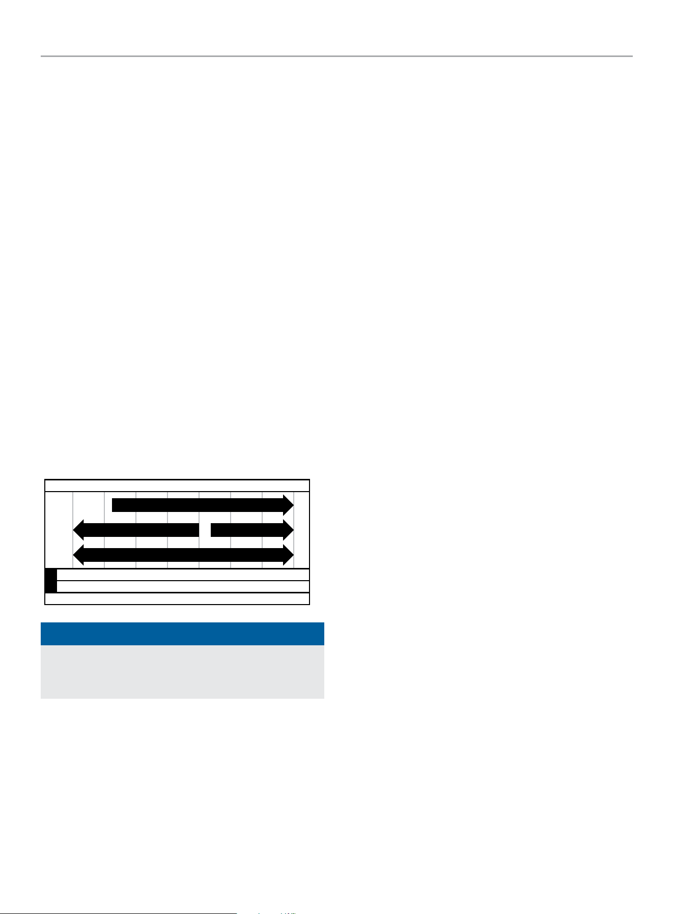
201464 - REAR TINE TILLER
SPECIFICATIONS
35
SPECIFICATIONS
Tiller Specifications
Model
....................................................... 201464
Tine Diameter ................................... 13.8 in. (350 mm)
Tilling Width (in.) ...................................19 in. (483 mm)
Tilling Depth (in.) ....................................8 in. (203 mm)
Tilling Depth Adjustments............. 1.6 in. (41 mm) Increments
Wheel Diameter ....................................13 in. (330 mm)
Transmission Gear Oil ...................... API rated GL-4 or GL-5
..............Viscosity of SAE 140, SAE 85W-140 or SAE 80W-90
Net Weight ........................................... 159 lb. (72 kg)
Length ............................................ 58.7 in. (149 cm)
Width .............................................. 19.7 in. (50 cm)
Height ............................................. 49.6 in. (126 cm)
Engine Specifications
Displacement .................................................212 cc
Type ................................................... 4-Stroke OHV
Fuel Capacity ....................................... 0.82 gal. (3.1 L)
Oil Capacity ................................... 16.9 fl. oz. (500 ml)
Oil Type ..................................................... 10W-30
-20 0 20 40 60
Ambient temperature
Recommended Engine Oil Type
80 100 120
-28.9
°F
°C
-17.8 -6.7 4.4 15.6 26.7 37. 8 48.9
10W-30
5W-30 Full Synthetic
10W-405W-30
NOTICE
Temperature will affect engine oil and engine performance.
Change the type of engine oil used based on temperature
shown in the “Recommended Engine Oil Type” table.
Fuel Specifications
Use regular unleaded gasoline with a minimum octane rating of 87
and an ethanol content of less than 10% by volume. DO NOT USE
E15 or E85. DO NOT OVERFILL.
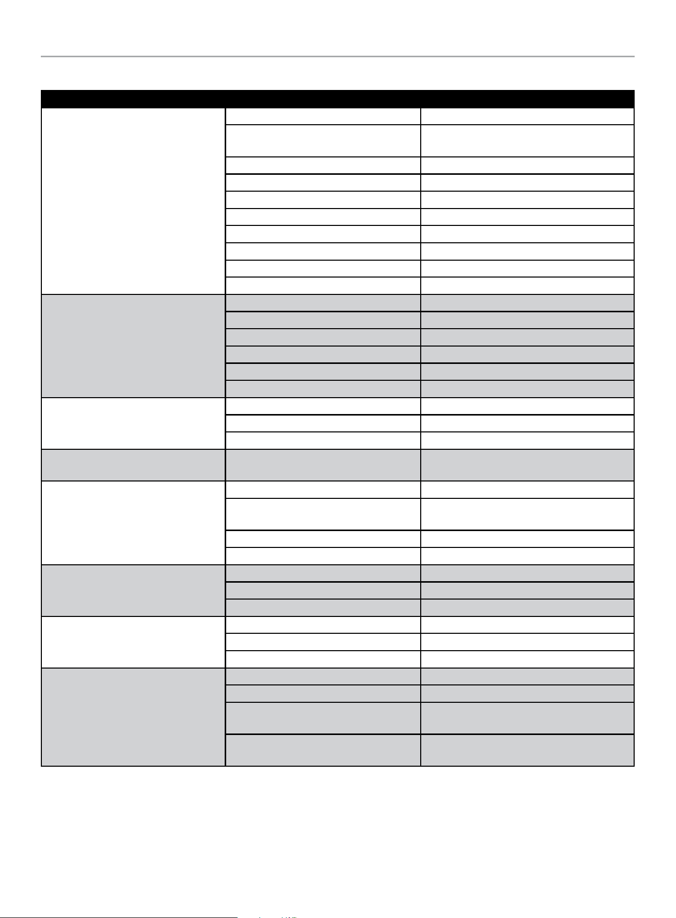
201464 - REAR TINE TILLER
TROUBLESHOOTING
36
TROUBLESHOOTING
Problem Cause Solution
Engine does not start
Spark plug wire disconnected. Reconnect wire.
Engine Throttle Control Lever incorrectly
set.
Put lever in “START” position.
Fuel tank empty. Add fuel.
Choke control in incorrect position. Move to “CHOKE” position.
Stale gasoline. Drain fuel and add fresh fuel.
Dirty air filter. Clean or replace filter.
Defective or incorrectly gapped spark plug. Inspect spark plug.
Carburetor out of adjustment. Contact Technical Support Team.
Misadjusted throttle control. Contact Technical Support Team.
Dirt or water in fuel tank. Contact Technical Support Team.
Engine runs poorly
Defective or incorrectly gapped spark plug. Inspect spark plug.
Dirty air filter(s). Clean or replace.
Carburetor out of adjustment. Contact Technical Support Team.
Stale gasoline. Replace with fresh gasoline.
Dirt or water in fuel tank. Contact Technical Support Team.
Engine cooling system clogged. Clean air cooling system.
Engine overheats
Engine cooling system clogged. Clean air cooling area.
Carburetor out of adjustment. Contact Technical Support Team.
Oil level is low. Check oil level.
Engine does not shut off
Misadjusted throttle control or ignition
switch.
Contact Technical Support Team.
Wheels and Tines will not turn
Improper use of controls. Review controls section.
Worn, broken, or misadjusted drive belt(s).
See “Checking and Adjusting Forward Drive
Belt Tension” or “Belt Tension Adjustment”.
Internal transmission wear or damage. Contact Technical Support Team.
Bolt loose in transmission pulley. Tighten bolt.
Tines turn, but wheels don’t
Wheel Drive Pins not in WHEEL DRIVE. See “Wheel Drive Pins”.
Bolt loose in transmission pulley. Tighten bolt.
Internal transmission wear or damage. Contact Technical Support Team.
Wheels Turn, but tines don’t
Tine holder mounting hardware missing. Replace hardware.
Bolt loose in transmission pulley. Tighten bolt.
Internal transmission wear or damage. Contact Technical Support Team.
Poor tilling performance
Worn tines. See “Tines” section.
Improper Depth Regulator setting. See “Depth Regulator Lever Adjustment”.
Incorrect throttle setting.
Adjust throttle on engine or speed control on
handelbar to highest setting.
Forward Drive Belt slipping.
See “Checking and Adjusting Forward Drive
Belt Tension” or “Belt Tension Adjustment”.

201464 - REAR TINE TILLER
TROUBLESHOOTING
37
Difficulty Starting Engine (Recoil)
Problem Cause Solution
Something wrong with the fuel system:
fuel supply is not smooth or no fuel
supply
There is no enough fuel in fuel tank and
fuel cock is closed.
Fill fuel, open fuel cock.
Air vent in the fuel filler cap is clogged. Dredge air vent.
Fuel cock is clogged. Clean first and then dredge.
Improper or clogged main oil flow hole. Readjust or clean. Blow to clear through.
Needle valve is not closed properly or start
hole is clogged.
Dismantle needle valve and repair, clean. Blow
to get through.
Float is damaged or sticking. Repair float.
Fuel is too filthy or deteriorated. Replace.
There is water in fuel. Replace.
Too much fuel in engine. Drain extra fuel. Dry up spark plug electrodes.
No spark
Too much carbon deposit and dirt around
electrodes.
Clear carbon deposits.
Too much carbon deposit and dirt around
electrodes.
Replace spark plug.
Too much carbon deposit and dirt around
electrodes.
Adjust to proper value.
Abnormal cylinder compression
Piston ring is at its wear limit. Replace.
Piston ring is broken. Replace.
Piston ring is sticking. Clear up carbon fouling.
Spark plug is not installed tightly or gasket
is missing.
Tighten with a gasket in.
Air leakage between cylinder block and
cylinder head.
Check cylinder gasket and the flatness of the
surface where the cylinder block contacts the
cylinder head.
Tighten cylinder head bolts in stipulated order
to stipulated torque.
Air leakage in the valves.
Check valve clearance and tightness. Repair if
necessary.
If engine still doesn’t start, contact our Technical Support Team for service and/or repair.
WARNING
– When testing the spark plug, never hold the high-voltage wire of the spark plug with wet hand.
– Make sure there is no spilled fuel outside the engine and that the spark plug isn’t covered with fuel.
– To prevent fire, keep sparks far away from the spark plug mounting hole.
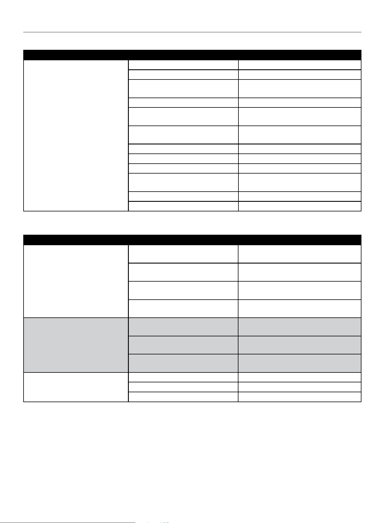
201464 - REAR TINE TILLER
TROUBLESHOOTING
38
Gasoline Engine: No Power
Problem Cause Solution
When increasing throttle, speed increase
slow (or even decreases and stops
running)/poor compression
Air in fuel line or fuel line clogged. Exhaust air or dredge fuel line.
Main oil flow hole is not adjusted properly. Readjust.
In carburetor, needle valve hole and main
oil flow hole clogged.
Clean and blow to clear.
Fuel cock is clogged up. Clean/replace damaged part.
Too much carbon deposit in combustion
chamber.
Clear away.
Too much carbon fouling in muffler and
exhaust pipe.
Clear away.
Air cleaner is clogged up. Clean air cleaner filter element.
Intake pipe is leaking. Repair or replace.
Piston or cylinder or piston ring is worn. Replace the worn part.
Air leakage from the surface where the
cylinder block contacts the cylinder head.
Replace cylinder gasket.
Too big or too small valve clearance. Readjust.
Valve tightness is poor. Repair.
Gasoline Engine Running Roughly
Problem Cause Solution
Knocking sound
Piston, cylinder or piston ring is worn
excessively.
Replace the worn part.
Piston pin and piston pin hole are worn
excessively.
Replace piston or piston pin.
Piston pin and piston pin hole are worn
excessively.
Replace tie rod.
Roller bearing for crankshaft main shaft is
worn.
Replace roller bearing.
Abnormal combustion
Engine is too hot.
Shut down and allow engine to cool off before
troubleshooting.
Too much carbon deposit in combustion
chamber.
Clear away.
Improper blended ethanol gasoline level,
E15 or higher. Old fuel (30 days or older)
New E10 or lower ethanol blended fuel.
Spark plug
There is water in float chamber. Clean.
Improper spark plug electrodes clearance. Adjust.
Faulty spark plug. Replace spark plug.
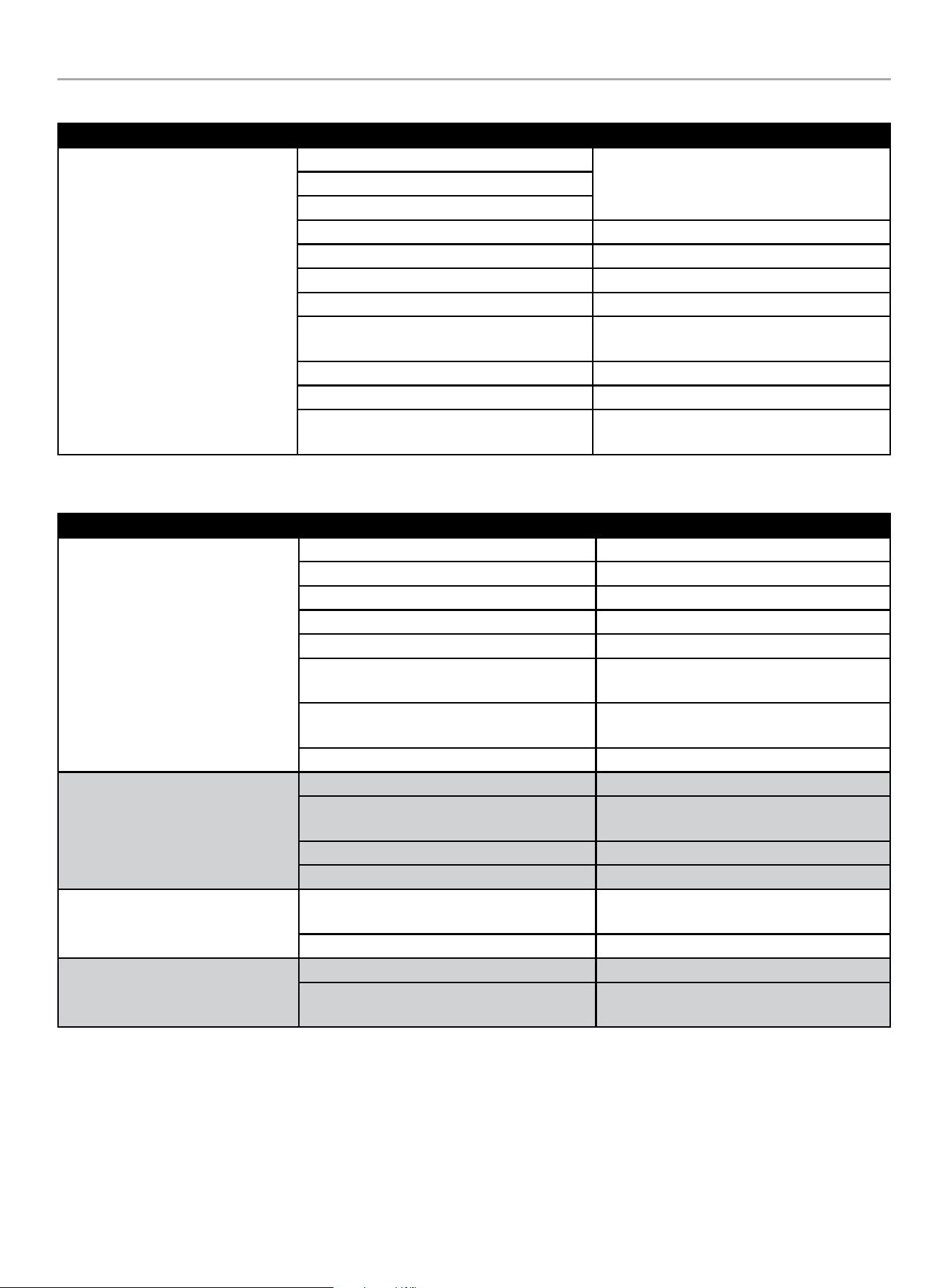
201464 - REAR TINE TILLER
TROUBLESHOOTING
39
Stops Suddenly When Running
Problem Cause Solution
Stops suddenly while running
Operated on a hill.
Keep engine oil level within targets and operate
tiller on inclines less than 15 degrees, or
disconnect oil sensor wire temporarily.
Unit bounces or hops.
Pulling back swiftly on the handlebars.
Fuel is empty. Refill fuel.
Carburetor is clogged. Check fuel line and dredge.
Float is leaking. Repair.
Needle valve is stuck. Dismantle float chamber and eliminate.
Spark plug is punctured, or short-circuited by
carbon deposit.
Replace spark plug.
Side electrode of spark plug is dropped out. Replace spark plug.
Ignition coil is punctured or short-circuited. Replace ignition coil.
Cylinder is seriously scored and valve dropped
out.
Repair or replace damaged parts.
Engine is Overheating
Problem Cause Solution
Engine is overheating
Oil level is low Fill oil to proper level
Exhaust pipe blocked up Clean exhaust pipe
Shroud leaking Repair damaged part
Cooling fins blocked by foreign matter Clean cooling fins
Cooling fan loosened and malfunctioning. Reinstall properly
Connection rod deformation has made piston
and cylinder bushing side wear
Replace connection rod
Cylinder or piston or piston ring is worn and
made a space between cylinder and crankcase
Replace the worn parts
Crankshaft main bearing burned out Replace main bearing
Beating sound
Piston, piston ring or cylinder is worn Replace the worn part
Connection rod or piston pin and piston pin
hole are worn
Replace the worn part
Crankshaft main neck is worn Replace the worn bearing
Piston ring is broken Replace piston ring
Metal beating sound when abnormal
combustion occurs
Too much carbon deposit in combustion
chamber
Clear away carbon deposit
Insufficient electrode clearance of spark plug Adjust electrode clearance properly
Other
Improper valve clearance Readjust valve clearance properly
Fly wheel is not connected with crankshaft
tightly
Tighten
For further technical support:
Technical Support Team
Toll Free 1-877-338-0999
support@championpowerequipment.com

WARRANTY*
CHAMPION POWER EQUIPMENT
2 YEAR LIMITED WARRANTY
Warranty Qualifications
To register your product for warranty and FREE lifetime call center
technical support please visit:
https://www.championpowerequipment.com/register
To complete registration you will need to include a copy of the
purchase receipt as proof of original purchase. Proof of purchase
is required for warranty service. Please register within ten (10)
days from date of purchase.
Repair/Replacement Warranty
CPE warrants to the original purchaser that the mechanical and
electrical components will be free of defects in material and
workmanship for a period of two years (parts and labor) from
the original date of purchase and 180 days (parts and labor) for
commercial and industrial use. Transportation charges on product
submitted for repair or replacement under this warranty are the
sole responsibility of the purchaser. This warranty only applies to
the original purchaser and is not transferable.
Do Not Return The Unit To The Place Of
Purchase
Contact CPE’s Technical Service and CPE will troubleshoot any
issue via phone or e-mail. If the problem is not corrected by
this method, CPE will, at its option, authorize evaluation, repair
or replacement of the defective part or component at a CPE
Service Center. CPE will provide you with a case number for
warranty service. Please keep it for future reference. Repairs or
replacements without prior authorization, or at an unauthorized
repair facility, will not be covered by this warranty.
Warranty Exclusions
This warranty does not cover the following:
Normal Wear
Products with mechanical and electrical components need
periodic parts and service to perform well. This warranty does not
cover repair when normal use has exhausted the life of a part or
the equipment as a whole.
Installation, Use and Maintenance
This warranty will not apply to parts and/or labor if the product is
deemed to have been misused, neglected, involved in an accident,
abused, loaded beyond the product’s limits or modified. Normal
maintenance is not covered by this warranty and is not required to
be performed at a facility or by a person authorized by CPE.
Other Exclusions
This warranty excludes:
– Cosmetic defects such as paint, decals, etc.
– Wear items such as filter elements, o-rings, etc.
– Failures due to acts of God and other force majeure events
beyond the manufacturer’s control.
– Problems caused by parts that are not original Champion
Power Equipment parts.
Limits of Implied Warranty and
Consequential Damage
Champion Power Equipment disclaims any obligation to cover
any loss of time, use of this product, freight, or any incidental
or consequential claim by anyone from using this product.
THIS WARRANTY AND THE ATTACHED U.S. EPA and/or CARB
EMISSION CONTROL SYSTEM WARRANTIES (WHEN APPLICABLE)
ARE IN LIEU OF ALL OTHER WARRANTIES, EXPRESS OR IMPLIED,
INCLUDING WARRANTIES OF MERCHANTABILITY OR FITNESS
FOR A PARTICULAR PURPOSE.
A unit provided as an exchange will be subject to the warranty
of the original unit. The length of the warranty governing the
exchanged unit will remain calculated by reference to the purchase
date of the original unit.
This warranty gives you certain legal rights which may change
from state to state or province to province. Your state or province
may also have other rights you may be entitled to that are not
listed within this warranty.
Contact Information
Address
Champion Power Equipment, Inc.
6370 S Pioneer Way, Unit 101
Las Vegas, NV 89113 USA
www.championpowerequipment.com
Customer Service
Toll Free: 1-877-338-0999
info@championpowerequipment.com
Fax no.: 1-562-236-9429
Technical Service
Toll Free: 1-877-338-0999
tech@championpowerequipment.com
EMERGENCY 24 HOUR SUPPORT: 1-562-204-1188
*Except as otherwise stipulated in any of the following enclosed Emission Control System Warranties (when applicable) for the Emission Control System: U.S. Environment Protection Agency
(EPA) and/or California Air Resources Board (CARB).

CHAMPION POWER EQUIPMENT, INC. (CPE)
AND THE UNITED STATES ENVIRONMENTAL PROTECTION AGENCY (U.S. EPA.)
EMISSION CONTROL SYSTEM WARRANTY
Your Champion Power Equipment (CPE) engine complies with U.S. EPA emissions regulations.
YOUR WARRANTY RIGHTS AND OBLIGATIONS:
The U.S. EPA and CPE are pleased to explain the Federal Emission Control Systems Warranty on your 2024 small off-road engine and
engine powered equipment. New equipment that use small off-road engines must be designed, built and equipped to meet U.S. EPA
regulations.
CPE must warrant the exhaust and evaporative emission control system on your small off-road engine for the period listed below, provided
there has been no abuse, neglect, unapproved modification, or improper maintenance of your equipment.
Your emission control system may include parts such as: carburetors, fuel tanks, fuel lines, (for liquid fuel and fuel vapors), fuel caps,
valves, canisters, filters, clamps, connectors, and other associated components. Also included may be the fuel-injection system, the
ignition system, catalytic converter and other emission related assemblies. Where a warrantable condition exits, CPE will repair your small
off-road engine at no cost to you including diagnosis, parts and labor.
MANUFACTURER’S EMISSION CONTROL SYSTEM WARRANTY COVERAGE:
This emission control system is warranted for two years, subject to provision set forth below. If any emission related part on your engine is
defective, the part will be repaired or replaced by CPE.
OWNER WARRANTY RESPONSIBILITIES:
As the small off-road engine owner, you are responsible for the performance of the required maintenance listed in your Owner’s Manual.
CPE recommends that you retain all your receipts covering maintenance on your small off-road engine, but CPE cannot deny warranty
coverage solely for the lack of receipts or for your failure to ensure the performance of all scheduled maintenance.
As the small off-road engine owner, you should be aware that CPE may deny you warranty coverage if your small off-road engine or a part
has failed due to abuse, neglect, improper maintenance or unapproved modifications.
You are responsible for presenting your small off-road engine to an Authorized CPE distribution center, service center or alternate service
outlet as described in (3)(f) below or CPE dealer or CPE, Las Vegas, NV. as soon as the problem exists. The warranty repairs shall be
completed in a reasonable amount of time, not to exceed 30 days.
If you have any questions regarding your warranty coverage, you should contact:
Champion Power Equipment, Inc.
Customer Service
6370 S Pioneer Way, Unit 101
Las Vegas, NV 89113
1-877-338-0999
tech@championpowerequipment.com

EMISSION CONTROL SYSTEM WARRANTY
The following are specific provisions relative to your Exhaust and Evaporative Emission Control System (ECS) Warranty
Coverage.
1. APPLICABILITY: This warranty shall apply to 1997 and later model year small off-road engines.The ECS Warranty Period shall begin
on the date the new engine is delivered to its original, end-use purchaser, and shall continue for 24 consecutive months thereafter.
2. GENERAL EMISSIONS WARRANTY COVERAGE
CPE warrants to the original, end-use purchaser of the new engine or equipment and to each subsequent purchaser that each of its
small off-road engines is:
2a. Designed, built and equipped to conform to U.S. EPA emissions standards for spark-ignited engines at or below 19 kilowatts.
2b. Free from defects in materials and workmanship that cause the failure of a warranted part to be identical in all material respects
to the part as described in the engine manufacturer’s application for certification for a period of two years.
3. THE WARRANTY ON EMISSION-RELATED PARTS WILL BE INTERPRETED AS FOLLOWS:
3a. Any warranted part that is not scheduled for replacement as required maintenance in the Owner’s Manual shall be warranted for
the ECS Warranty Period. If any such part fails during the ECS Warranty Period, it shall be repaired or replaced by CPE according
to Subsection “d” below. Any such part repaired or replaced under the ECS Warranty shall be warranted for any remainder of the
ECS Warranty Period.
3b. Any warranted, emissions-related part which is scheduled only for regular inspection as specified in the Owner’s Manual shall be
warranted for the ECS Warranty Period. A statement in such written instructions to the effect of “repair or replace as necessary”,
shall not reduce the ECS Warranty Period. Any such part repaired or replaced under the ECS Warranty shall be warranted for the
remainder of the ECS Warranty Period.
3c. Any warranted, emissions-related part which is scheduled for replacement as required maintenance in the Owner’s Manual shall
be warranted for the period of time prior to the first scheduled replacement point for that part. If the part fails prior to the first
scheduled replacement, the part shall be repaired or replaced by CPE according to Subsection “d” below. Any emissions-related
part repaired or replaced under the ECS Warranty, shall be warranted for the remainder of the ECS Warranty Period prior to the
first scheduled replacement point for such emissions-related part.
3d. Repair or replacement of any warranted, emissions-related part under this ECS Warranty shall be performed at no charge to the
owner at a CPE Authorized Service Outlet.
3e. The owner shall not be charged for diagnostic labor which leads to the determination that a part covered by the ECS Warranty is in
fact defective, provided that such diagnostic work is performed at a CPE Authorized Service Outlet.
3f. CPE shall pay for covered emissions warranty repairs at non-authorized service outlets under the following circumstances:
i. The service is required in a population center with a population over 100,000 according to U.S. Census 2000 without a CPE
Authorized Service Outlet AND
ii. The service is required more than 100 miles from a CPE Authorized Service Outlet. The 100 mile limitation does not apply in the
following states: Alaska, Arizona, Colorado, Hawaii, Idaho, Montana, Nebraska, Nevada, New Mexico, Oregon, Texas, Utah and
Wyoming.
3g. CPE shall be liable for damages to other original engine components or approved modifications proximately caused by a failure
under warranty of an emission-related part covered by the ECS Warranty.
3h. Throughout the ECS Warranty Period, CPE shall maintain a supply of warranted exhaust and evaporative emission-related parts
sufficient to meet the expected demand for such exhaust and evaporative emission-related parts.
3i. Any CPE Authorized and approved emission-related replacement part may be used in the performance of any ECS Warranty
maintenance or repair and will be provided without charge to the owner. Such use shall not reduce CPE’s warranty obligation.
3j. Unapproved add-on or modified parts may not be used to modify or repair a CPE engine. Such use voids this ECS Warranty and
shall be sufficient grounds for disallowing an ECS Warranty claim. CPE shall not be liable hereunder for failures of any warranted
parts of a CPE engine caused by the use of such an unapproved add-on or modified part.

EMISSION-RELATED PARTS INCLUDE THE FOLLOWING: (using those portions of the list applicable to the
engine)
Systems covered by this
warranty
Parts Description
Fuel Metering System Carburetor and internal parts (and/or pressure regulator or fuel injection system) Air/fuel ratio
feedback and control system. Cold start enrichment system.
Air Induction System Controlled hot air intake system. Air Filter, Intake manifold.
Ignition System Spark plug. Magneto or electronic ignition system. Spark advance/retard system.
Exhaust Gas Recirculation (EGR)
System
EGR valve body, and carburetor spacer if applicable. EGR rate feedback and control system.
Air Injection System Air pump or pulse valve. Valves affecting distribution of flow. Distribution manifold.
Catalyst or Thermal Reactor
System
Catalytic converter. Thermal reactor. Exhaust manifold.
Particulate Controls Traps, filters, precipitators, and any other device used to capture particulate emissions.
Miscellaneous Parts Vacuum, temperature, and time sensitive valves and switches. Electronic controls. Hoses, belts,
connectors, and assemblies.
Evaporative Controls Fuel Tank, Fuel Cap, Fuel Lines (for liquid fuel & fuel vapors), Fuel Line Fittings, Clamps, Pressure
Relief Valves, Control Valves, Control Solenoids, Electronic Controls, Vacuum Control Diaphragms,
Control Cables, Control Linkages, Purge Valves, Gaskets, Liquid/Vapor Separator, Carbon Canister,
Canister Mounting Brackets, Carburetor Purge Port Connector.
TO OBTAIN WARRANTY SERVICE:
You must take your CPE engine or the product on which it is installed, along with your warranty registration card or other proof of original
purchase date, at your expense, to any Champion Power Equipment dealer who is authorized by Champion Power Equipment, Inc. to
sell and service that CPE product during his normal business hours. Alternate service locations defined in Section (3)(f) above must be
approved by CPE prior to service. Claims for repair or adjustment found to be caused solely by defects in material or workmanship will not
be denied because the engine was not properly maintained and used.
If you have any questions regarding your warranty rights and responsibilities, or to obtain warranty service, please write or call
Customer Service at Champion Power Equipment, Inc.
Champion Power Equipment, Inc.
6370 S Pioneer Way, Unit 101
Las Vegas, NV 89113
1-877-338-0999
Attn.: Customer Service
tech@championpowerequipment.com