
GPSMAP 400/500 Series Installation Instructions
Your GPSMAP 400/500 series chartplotter must be properly installed according to the following instructions. You need the appropriate
fasteners, tools, and mounts listed in each section. If you experience difculty installing the chartplotter, seek the assistance of a
professional installer, or contact Garmin Product Support.
Before installing your GPSMAP 400 or 500 series chartplotter, conrm that the package contains the items listed on the box. If any parts are
missing, contact your Garmin dealer immediately.
WARNING: See the Important Safety and Product Information guide in the product box for product warnings and other important
information.
WARNING: Always wear safety goggles, ear protection, and a dust mask when drilling, cutting, or sanding.
NotIce: When drilling or cutting, always check the opposite side of the drilling or cutting surface.
To install and use your chartplotter:
1 Selectamountinglocation(page2).
2. Mountthechartplotter(page2).
3. Installthetransducer,ifapplicable(page3).
4. Installthewiringharness(page6).
5. ConnectthechartplottertoaNMEA2000network(optional,ifapplicable)(page8).
6. Connectthecablestothechartplotter(page9).
7. Testtheinstallation(page9).
Chartplotter Functionality Matrix
The chartplotters in the GPSMAP 400/500 series have different functionality based on model number. Use this matrix to determine the feature
set and installation requirements of your chartplotter.
Chartplotter NMEA 2000 NMEA 0183 Garmin CANet Sonar
GPSMAP 420/430/430x/440/440x/450 No Yes Yes “s”versiononly
GPSMAP 520/525/530/535/540/545/550/555 No Yes Yes “s”versiononly
GPSMAP 421/441/451 Yes Yes No “s”versiononly
GPSMAP 431/531 No Yes No “s”versiononly
GPSMAP 521/526/536/541/546/551/556 Yes Yes No “s”versiononly
March2012 190-01074-02Rev.C PrintedinTaiwan

2 GPSMAP 400/500 Series Installation Instructions
Selecting a Mounting Location
Consider the following when selecting a location to mount your chartplotter:
• The location provides optimal viewing as you operate your boat.
• The location allows for easy access to the keypad on the chartplotter.
• The location is strong enough to support the weight of the chartplotter and protect it from excessive vibration or shock.
• Refer to the compass-safe distance table on page 10 to avoid interference with your magnetic compass.
• The location allows room for the routing and connection of the cables. There should be at least a 3 in. (8 cm) clearance behind the case.
NotIce: Do not mount the chartplotter in an area that is exposed to extreme temperature or conditions. The temperature range for the chartplotter is
from 5°F to 131°F (from -15°C to 55°C). Extended exposure to temperatures exceeding this range (in storage or operating conditions) may cause failure
of the LCD screen. This type of failure and related consequences are not covered by the manufacturer’s limited warranty.
Mounting the Chartplotter
There are two mounting options for the chartplotter:
• Surface Mount—mount the chartplotter onto a bracket (included) that attaches to the console or overhead. The compact waterproof
chartplotter housing is suitable for mounting in exposed locations or at the navigation station.
• Flush Mount—use an optional ush mount kit to mount the chartplotter into a at panel. For more information on the optional ush mount
kit, visit www.garmin.com or contact your local Garmin dealer.
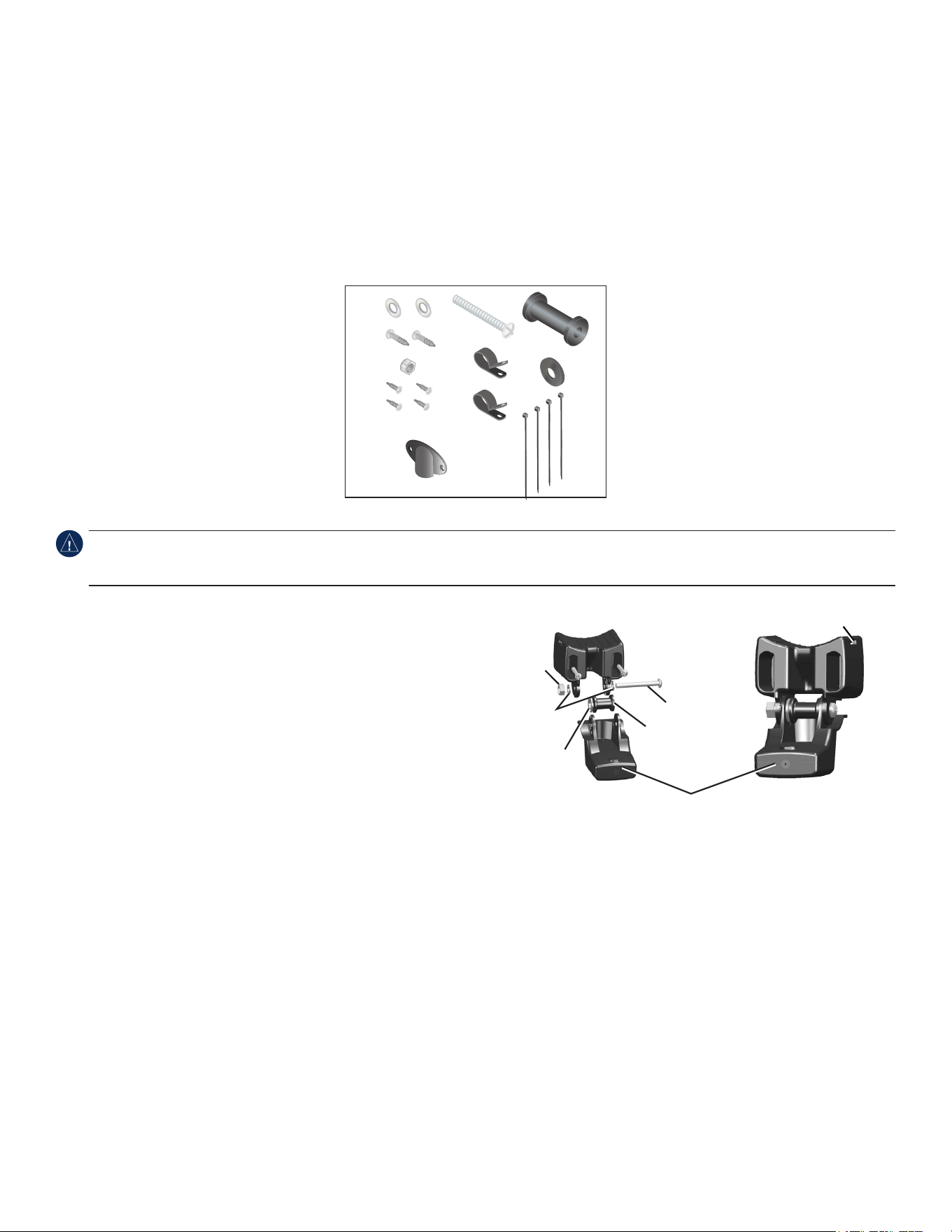
Surface-Mounting the Chartplotter
Use the included bracket to surface-mount the chartplotter. You will need the following tools and fasteners:
• Drill
• Phillips or at screwdriver
• Three #8 (4 mm) pan-head machine bolts with matching nuts and washers and a
5
/
32
in. (5 mm) drill bit, or three #8 pan-head self-tapping
screws and a
1
/
16
in. (1.5 mm) drill bit for drilling starter holes.
NotIce: Use pan-head machine bolts or self-tapping screws to secure the swivel base. If you use screws with countersunk heads, you may damage the
mounting bracket.
To mount the bracket assembly:
1. Usingtheswivelbaseasatemplate,markthelocationofthethreeholesthatsecurethebrackettothe
mountingsurface.
2. Drillthemountingholes.
• Ifyousecurethebasewithmachinebolts,drillthree
5
/
32
in.(5mm)holesatthelocationsyou
marked.
• Ifyousecurethebasewithself-tappingscrews,drillthree
1
/
16
in.(1.5mm)starterholesatthe
locationsyoumarked.Donotmakethestarterholesdeeperthanhalfthescrewlength.
3. Securetheswivelbasewiththreeboltsorscrews.Donotovertightenthescrewsorbolts;youmay
damagetheswivelbase.
4. Placetheswivelmountbracketovertheswivelbaseandsecureitwiththeshortknob.
To install the chartplotter on the mounting bracket:
1.Aligntheslotonthebackofthechartplotterwiththelongmountingknob,andslidethe
chartplotterintoplace.Ifnecessary,adjusttheknobtospreadthebracketarmsapart.
(Turntheknobcounter-clockwisetowidenthebracketarmsandclockwisetotighten.)
2.Adjustthechartplotterangle,andtightenthelongmountingknobuntilthechartplotter
issnug.
3. Rotatetheswivelmountbracketbytwistingitleftorright.Thebracketclicksasyou
turnit.Selectagoodviewingangle,andthentightenbothknobs.
OK
GPSMAP 400/500 Series Installation Instructions 3
Installing a Transducer
Consult the chartplotter feature matrix on page 1 to determine if your chartplotter is capable of using sonar. The following transducer
installation procedures are only applicable to sonar-capable chartplotters.
Note: The following procedures contain installation instructions for the transducer included with the “s” model GPSMAP 400/500 series
chartplotters. If you choose to use a different transducer, installation instructions are provided in the transducer kits. Some transducers might
have to be installed by a professional marine installer.
Proper transducer installation is key to getting the best performance from your sonar-capable chartplotter. Be sure you have the following
components in the transducer package, as well as the following tools:
Transducer Package
• Transom-mounttransducer(notpictured)
A –5mmatwashers(2)
B –5×30mmscrews(2)
C –10-32locknut(1)
D –4×12mmscrew(4)
E –10-32×1.75in.screw(1)
F –
1
/
4
in.cableclamps(2)
G –Plasticspacer(1)
H –
1
/
4
in.rubberwasher(1)
I –Cabletie,5.6in.(4)
J –Cableentrycover(1)
F
H
C
D
I
J
G
E
A
B
Tools Needed
• Drillanddrillbits
•
3
/
8
in.(9.5mm)wrenchorsocket
• Maskingtape
• Number2Phillipsscrewdriver
• Marinesealant
NotIce: Do not cut the transducer lead or any part of the transducer cable. Cutting the transducer cable voids your warranty. The cable cannot be
spliced and connected to any existing (Garmin or non-Garmin) transducer cables. If the transducer lead is too short, extension cables are available from
your Garmin dealer.
Assembling the Transducer
1.Inserttherubberwasher(H)andtheplasticspacer(G)intothetransducer
atthesametime.DONOTlubricatetherubberwasher.
2. Routethepower/datacabletowardthebackofthetransducer.Slidethe
transducerintothetransducermount.
3.Placea5mmatwasher(A)onthe10-32×1.75in.screw(E),andinsert
thescrewthroughthetransducermount,thespacer,andtherubber
washer.
4.Placetheremaining5mmatwasher(A)ontheexposedendofthe10-32
×1.75in.screw.Installthe10-32locknut(C)ngertight.Retightenthe
transducerafterinstallationontheboat.
Mounting the Transducer on a Transom
When selecting a transom-mount location, consider the following for optimal performance:
• For your sonar to operate properly, the transducer must be located in calm water.
• Mount the transducer as close to the center of the boat as possible.
• Do not mount the transducer in locations where it might be jarred when launching, hauling, or storing.
• Do not mount the transducer in the path of the propeller on single-drive boats. The transducer can cause cavitation that can degrade the
performance of the boat and damage the propeller. On twin-drive boats, mount the transducer between the drives, if possible.
Note: Do not mount the transducer behind strakes, struts, ttings, water intake or discharge ports, or anything that creates air bubbles or
causes the water to become turbulent. The transducer must be in clean (non-turbulent) water for optimal performance.
Back of the transducer
Cable tie slot
E
G
H
A
C

4 GPSMAP 400/500 Series Installation Instructions
To mount the transducer on a transom:
1. Positionthetransducermountattheselectedtransomlocation.Makesurethetransducerisparallelwiththewaterline.Markthecenter
locationsofeachholeonthetransducermount.
Apply marine sealant to all screw
threads to prevent water from
seeping into the transom.
Mount the transducer
cable cover far above
the waterline.
The transducer should
extend
1
/
8
in. (3.2 mm)
below a berglass hull or
3
/
8
in. (9.5 mm) below an
aluminum hull.
Ensure that the transducer is
below water level when the boat
is on plane at high speed.
Do not mount the transducer directly in the path of the
propeller. The transducer can cause cavitation that may
degrade the boat performance and damage the propeller.
Mount the transducer parallel
with the bottom.
2. Drill
5
/
32
in.(4mm)pilotholesapproximately1in.(25mm)deepatthemarkedlocations.Toavoiddrillingtheholestoodeep,wrapapieceof
tapearoundthebitat1in.(25mm)fromthepointofthebit.
3. Applymarinesealanttothe5×30mmscrews(B).Attachthetransducerassemblytothetransomusingthe5×30mmscrews.Adjustthe
transducerassemblytoextendbeyondthebottomofthetransomapproximately
1
/
8
in.(3.2mm)onberglasshullsor
3
/
8
in.(9.5mm)on
aluminumhulls.Adjustthetransducerassemblytobealignedparallelwiththebottom.
4. Tightenthe10-32lockingnutuntilittouchesthemountingbracket,andthentighten
1
/
4
turnmore.(Donotovertighten.)
5.Placetherstcableclamp(F)onthetransducercable,approximatelyonethirdofthedistancebetweenthetransducerandthetopofthe
transom.
6. Markthelocation.Drilla
1
/
8
in.(3.2mm)pilotholeapproximately
3
/
8
in.(9.5mm)deep.
7.Attachthecableclampusingoneofthe4×12mmscrews(D).Coatthescrewwithmarinesealantbeforeinstallation.Repeatsteps5and6
usingtheothercableclamp.
8. RoutethetransducercabletotheGPSMAP400/500serieschartplotter.
NotIce: Avoid routing the cable close to electrical wires or other sources of electrical interference.
9. TestthetransducerinstallationafteryoucompletetheGPSMAP400/500serieschartplotterinstallation.Seepage9.
Mounting a Transducer on a Trolling Motor
1.Withtheridgesofthebandfacingup,slidethelargecabletiethroughtheslotonthetransducermountuntilequallengthsextendonboth
sidesofthemount.
NotIce: For cold water and heavy timber or debris areas, a metal 4-5 in. (100-125 mm) worm gear clamp is recommended instead of the plastic
cable tie.
2. Positionthemountgasketonthecurvedtopofthetransducermount.
3.Withthefrontofthetransducerpointedawayfromthetrollingmotorpropeller,placethetransducer
assemblyagainstthemotorbodyofthetrollingmotor.
4.Wrapthetwoendsofthecabletiearoundthemotorbody.Placethepointedendofthecabletiethrough
thefastenerholeontheoppositeendandpullitthroughuntilitissnugbutnottight.(Thecabletieclicks
whenyoupullit.)
5. Positionthetransducersothatitisparallelwiththebottomwheninuse,makingsurethegasketis
alignedproperly.Pullthecabletieenduntiltight.Trimofftheexcessifnecessary.Tightenthelockingnut
untilittouchesthemountingbracket,andthentighten
1
/
4
turnmore.(Donotovertighten.)
Cable tie
Front of the transducer
GPSMAP 400/500 Series Installation Instructions 5
6.RoutethetransducercabletotheGPSMAP400/500serieschartplotterusingcabletiestosecurethecabletothemotorshaft.Youcanll
theforward-facingportion(exceptthecabletiepocket)ofthetransducermountwithsealanttoavoidaccumulatingdebris.
NotIce: Leave some slack in the cable to avoid damage while using the trolling motor.
NotIce: Avoid routing the cable close to electrical wires or other sources of electrical interference.
Shoot-Thru-Hull Installation
To avoid drilling a hole to mount a thru-hull transducer, a transom-mount transducer can be secured with epoxy inside a boat (shoot-thru-hull
installation). This type of installation can provide better noise reduction and allow you to use a higher gain setting. For a transducer to be
mounted inside the hull (shoot-thru, not thru-hull), the boat must be berglass with no core. Contact your boat manufacturer if you are unsure.
Professional installation might be necessary.
Some transducers are specically designed to be mounted inside a berglass hull. The standard plastic transom-mount transducer can also be
mounted using this method. If using a temperature-sensing transducer, the temperature displayed reects the hull temperature.
Note: A solid berglass hull can be no more than
5
/
8
in. (9.53 mm) thick when using a 500 W transducer, and no more than 1 in. (25.4 mm)
thick when using a 1 kW transducer. 1 kW transducers are only compatible with either the GPSMAP 525/535/545/555/526/536/546/556 or with
non “s” models compatible with a GSD 22.
When installing a transducer, consider the following:
• The hull must be composed of solid berglass without air bubbles, laminates, llers, or dead air space.
• The location must be in an area of clean (non-turbulent) water at all speeds.
• The location must not be over any strakes or behind any obstruction on the hull that would create turbulence.
Note: Many modern hulls have a dedicated pocket for shoot-thru-hull transducer installation. If you are unsure whether your hull is equipped
with a pre-located pocket, contact your hull manufacturer.
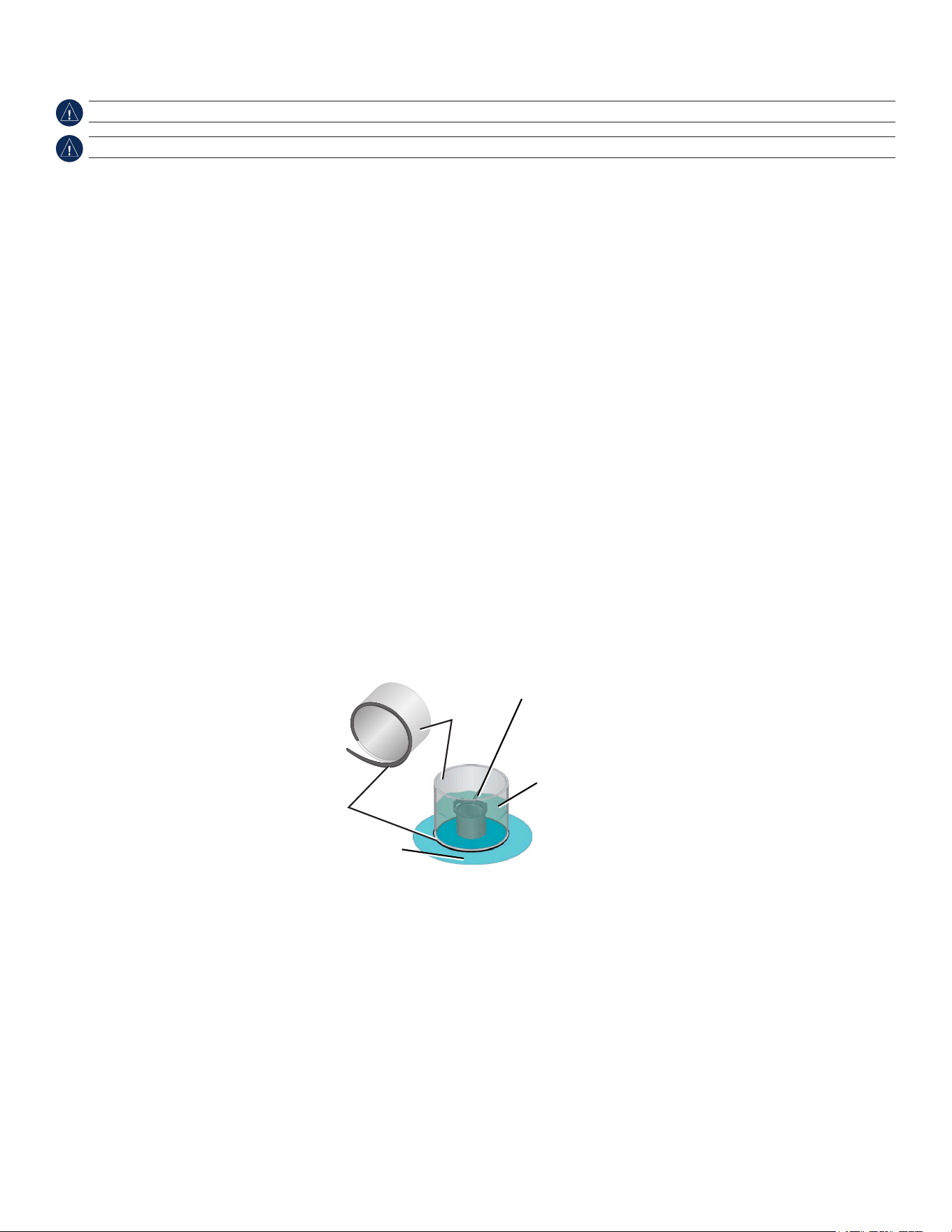
To test the location:
1. FabricateatestdevicefromasectionofPVCpipeoracan,asshowninthefollowingillustration.
2. TemporarilysealthetestdevicetothehullwithcaulkingorRTVsealer,andllthetestdevicewithwaterorlightmineraloil.
3. Placethetransducerinthewater,pointeddirectlyatthebottom,weighteddown.Setthedeviceforoptimumperformance.Ifthesonar
performanceissignicantlydegraded,anotherlocationmustbetested.
Testing the Location
PVC pipe
or a can
Weight the transducer
to hold it in place.
Fill a pipe or a can with
water or a light mineral oil.
Hull surface
Strip caulk or
RTV sealer
To permanently install the transducer:
1. Lightlysandthesurfaceofthehullandthefaceofthetransducerwith400-gritwetordrysandpaper.
2.Buildadamusingstripcaulkabout
1
/
4
in.(6mm)tall.Pourabout
1
/
8
in.(3mm)oftwo-part,slow-cureepoxyintothedam.
3. Placethetransducerintheepoxy,turningthetransducertoworkoutanyairbubbles.
4.Weightthetransducerinplace,andallowittocurefor24hours.
6 GPSMAP 400/500 Series Installation Instructions
Installing the Wiring Harness
The chartplotter comes with a wiring harness that connects the chartplotter to power and to optional NMEA 0183 and Garmin CANet devices.
If applicable, the wiring harness also connects the chartplotter to a transducer.
The wiring harness does not connect to a NMEA 2000 network. For instructions on connecting to a NMEA 2000 network with compatible
devices, see page 8.
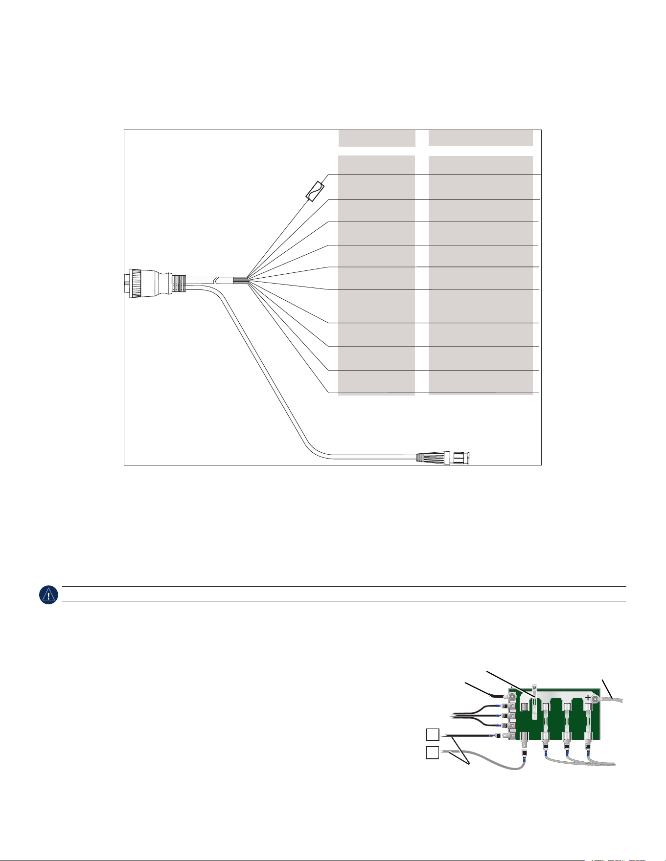
GPSMAP 400/500 Series Wiring Harness
>
>
>
>
To transducer (if applicable)
Red
Black
Accessory on
Blue
CANet L (if applicable)
CANet H (if applicable)
Alarm low
Wire Color Wire Function
Power (10–32 Vdc*)
Ground
(power and NMEA 0183)
NMEA 0183 port 1 Tx (out)
Brown
Grey
Violet
Green
White
Orange
Yellow
To the GPSMAP 400/500
series chartplotter
Fuse
3 A
NMEA 0183 port 1 Rx (in)
NMEA 0183 port 2 Tx (out)
NMEA 0183 port 2 Rx (in)
Notes:
• UseanAGC/3AG-3Ampreplacementfuse.
• Ifitisnecessarytoextendthepowerandgroundwires,use22AWGwire.
• Youcanwiretheharnessdirectlytothebattery,orifyourboathasanelectricalsystem,youmightbeabletowiretheharnesstoan
unusedholderonthefuseblock.
• Donotcutthetransducercable,becausethisvoidsyourwarranty.
NotIce: The maximum input voltage is 32 Vdc*. Do not exceed this voltage because this can damage the chartplotter and void the warranty.
Note: During a typical installation, use only the red and black wires. The other wires do not have to be connected for normal operation of the
chartplotter. For information on connecting to a NMEA 0183- or Garmin CANet-compatible device, see page 8.
Connecting the Wiring Harness to Power
1. Useatestlightorvoltmetertodeterminethepolarityofthevoltagesource.
2. Connectthered(+orpositive)wiretothepositivevoltageterminal.(Ifyouusethe
fuseblockontheboat,routethepositiveconnectionthroughthefuse,asshownonthe
diagram.)
3. Connecttheblack(-orground)wiretothenegativevoltageterminal.
4. Installorcheckthe3Afuse(inthein-linefuseholder,oronthefuseblockoftheboat).
Fuse Block Example
—
+
Boat ground
3 A fuse
To 10–32 Vdc* boat supply
To device
* Certain GPSMAP 400/500 series chartplotters can be connected to higher-voltage power sources. Refer to the Power section of the System Specications
on page 10 for more information.
GPSMAP 400/500 Series Installation Instructions 7
Connecting the Wiring Harness to a NMEA 0183 Device
You can connect the GPSMAP device to other NMEA compatible equipment, such as a DSC or AIS device. Refer to the wiring diagram for
connecting the chartplotter to NMEA 0183-compatible devices.
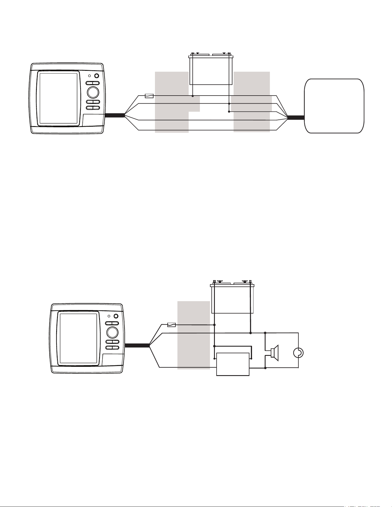
Wiring a GPSMAP 400/500 Series Chartplotter to a Standard NMEA 0183 Device
+
-
>
>
>
>
Red (power)
Black (ground)
Brown (in)
Blue (out)
Wire color
Power
Power ground
NMEA Ground
NMEA Rx/A (+)
NMEA Tx/A (+)
NMEA 0183
compliant device
GPSMAP
400/500
Series
Chartplotter
Battery
10–32 Vdc*
Fuse
3 A
Wire function
To connect the wiring harness to a NMEA 0183 device:
1. ForGarmindevices,theground(black)wiresserveasNMEA0183groundandmustbeattachedtogetheroronthesameterminalasthe
NMEA0183groundonyourNMEA0183device.RefertothewiringdiagramofyourNMEA0183deviceforwireidentication.
2. Connecttheblue(NMEA0183port1out)wirefromtheGPSMAP400/500wiringharnesstotheNMEA0183in(orRx/A+)wireonthe
wiringharnessoftheNMEA0183device,andthebrown(NMEA0183port1in)wiretotheNMEAout(orTx/A+)wireonthewiringharness
oftheNMEA0183device.
3. Repeatstep2usingthegreyandvioletwiresforanadditionalNMEA0183device.
4. Settheserialport(s)onthechartplottertouseNMEA0183data(standardorhighspeed).SeetheGPSMAP 400/500 Series Owner’s
Manualformoreinformation.
Connecting the Wiring Harness to an Optional Horn, Lamp, or Both
The GPSMAP 400/500 series chartplotter can be used with a lamp, a horn, or both, to sound or ash an alert when the chartplotter displays a
message. The alarm does not need to be wired for the GPSMAP 400/500 chartplotter to function. The alarm circuit switches to a low-voltage
state when the alarm sounds. The maximum current is 100 mA, and a relay is needed to limit the current from the chartplotter to 100 mA. To
select between visual and audible alerts, install a switch.
Wiring a GPSMAP 400/500 Series Chartplotter to a Horn, a Lamp, or Both
+
-
Relay
100 ma max
coil current
Horn
Lamp
GPSMAP
400/500
series
chartplotter
Fuse
3 A
Red
Black (ground)
Yellow (alarm)
Wire color
Battery
10–32 Vdc*
* Certain GPSMAP 400/500 series chartplotters can be connected to higher-voltage power sources. Refer to the Power section of the System Specications on
page 10 for more information.
8 GPSMAP 400/500 Series Installation Instructions
Connecting the Wiring Harness to a Garmin CANet Device
If your GPSMAP 400/500 series chartplotter is Garmin CANet-compatible, it can receive sonar information from a CANet-compatible Garmin
Sounder or Fishnder device. See the chartplotter functionality matrix on page 1 to determine whether your chartplotter is CANet compatible.
Using the CANet optimizes the performance of CANet-compatible devices, allowing sonar information from a sounder or shnder to be
shared with up to two CANet compatible Garmin chartplotters. A standard NMEA 0183 connection only allows depth, temperature, and speed
information to be sent to a single chartplotter, whereas a CANet connection provides full sonar readings, including Ultrascroll
™
, so you can
view and control the same information on your compatible chartplotter(s) as you can on your compatible Garmin sounder or shnder.
Note: To use the Garmin CANet with your device, you must purchase an optional CANet Kit. Contact your Garmin dealer, or visit
www.garmin.com.
Connecting the Chartplotter to a NMEA 2000 Network
If your GPSMAP 400/500 series chartplotter is NMEA 2000-compatible, you can connect it to an existing NMEA 2000 network on your boat
to share information with other connected NMEA 2000-compatible devices. If you do not have an existing NMEA 2000 network on your boat,
you will need to build one. See www.garmin.com for more information.
Note: NMEA 2000-compatible GPSMAP 400/500 series chartplotters are not packaged with NMEA 2000 connectors or cables. You will need
a NMEA 2000 T-connector and drop cable to connect it to an existing NMEA 2000 network. NMEA 2000 components are available from your
local Garmin dealer or marine dealer.
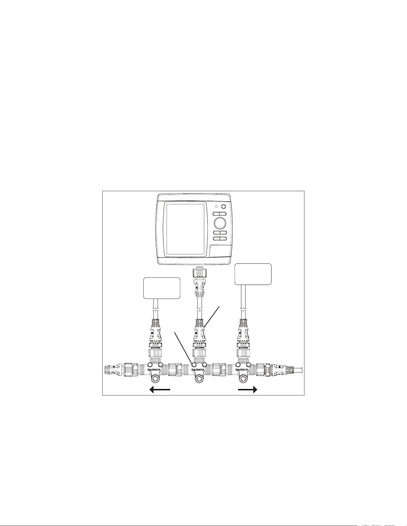
Connecting a NMEA 2000-compatible GPSMAP 400/500 Series
Chartplotter to an Existing NMEA 2000 Network
Existing NMEA 2000 network
Drop cable
(not included)
T-connector
(not included)
NMEA 2000
device
(not included)
NMEA 2000
device
(not included)
NMEA
2000-compatible
GPSMAP
400/500 series
chartplotter
To connect a NMEA 2000-compatible GPSMAP 400/500 series chartplotter to your existing NMEA 2000 network:
1. DetermineanappropriatelocationtoconnectthechartplottertoyourexistingNMEA2000network.
2. DisconnectonesideofaNMEA2000T-connectorfromthebackbonenearesttothelocationwhereyouwanttoconnectthechartplotter.
IfyouneedtoextendtheNMEA2000backbone,connectanappropriateNMEA2000backboneextensioncable(notincluded)tothesideof
theT-connectoryoudisconnected.
3. AddaT-connector(notincluded)totheNMEA2000backbone.
4. RouteaNMEA2000dropcablefromthechartplottertothetopoftheT-connectoryouaddedtoyourNMEA2000network.
Youcanuseadropcableupto20ft.(6m).Ifmorecableisneeded,addanextensiontoyourNMEA2000backbone,basedonthe
NMEA2000guidelines.
GPSMAP 400/500 Series Installation Instructions 9
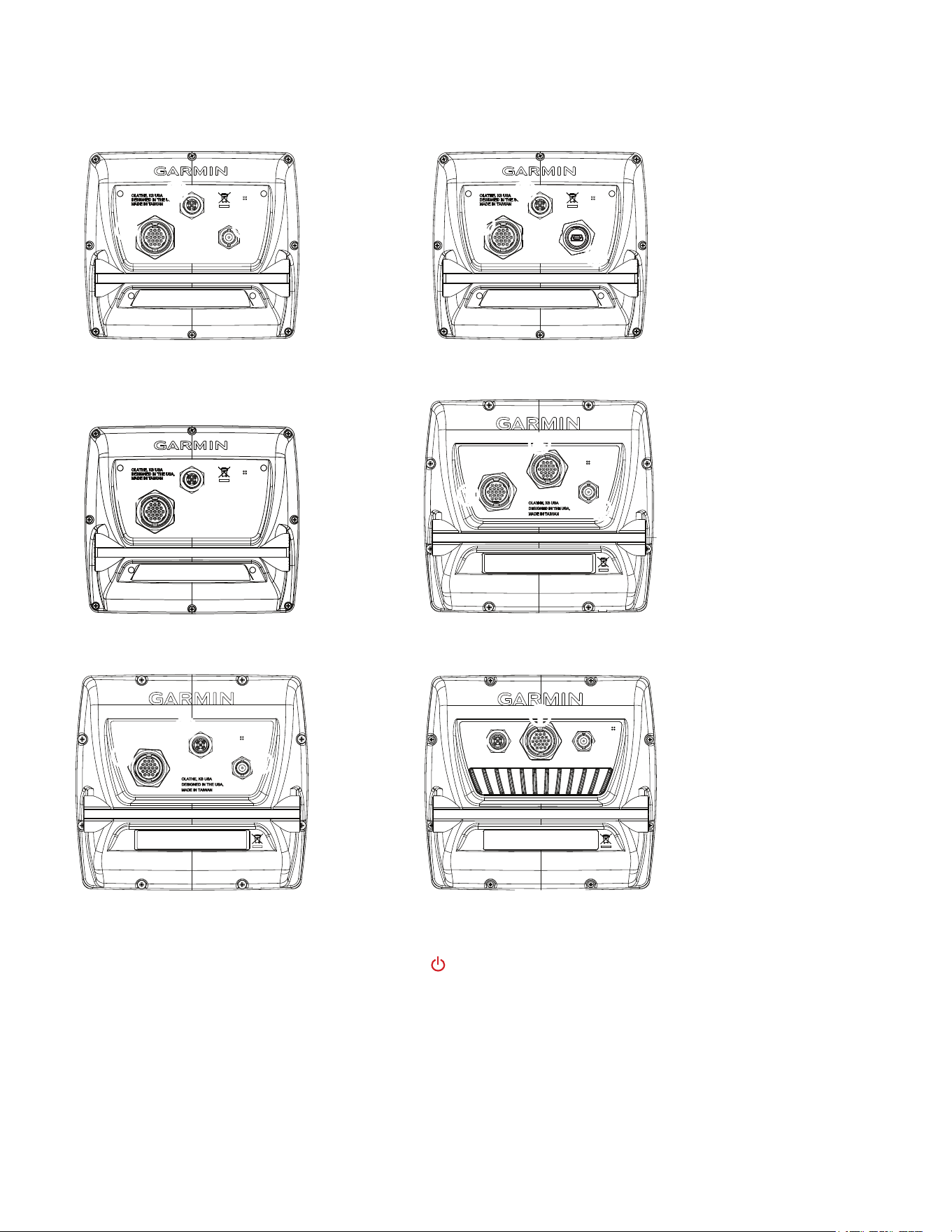
Connecting Cables to the Chartplotter
Use the diagrams below to help identify the connectors on the back of your GPSMAP 400/500 series chartplotter. Every possible chartplotter
conguration is not represented in the diagrams, but every possible connector type is listed for identication purposes. Every connector on the
back of the chartplotter may not be used for all installations.
➊
Wiring harness
➋
NMEA 2000
➌
External GPS antenna
(sold separately)
➍
Compatible XM
antenna with audio
adapter (sold
separately)
➎
Compatible XM
antenna (sold
separately)
➋
➌
➋
➊
➋
➌
➊
➋
➎
➊
➍
➋
➊
➊
➊
➌
➌
GPSMAP 421, 441, and 451 GPSMAP 430x and 440x
GPSMAP 530, 535, 540, and 545GPSMAP 420, 430, 431, 440, and 450
GPSMAP 521, 541, 551 GPSMAP 526, 536, 546, and 556
Testing the Installation
To turn on your chartplotter for the rst time, press and hold the PoWeR key until the chartplotter beeps and turns on. Using the RocKeR
and the SeLect keys, follow the screens to congure your chartplotter.
Testing the Optional Transducer Installation
Because water is necessary to carry the sonar signal from the sounder, the transducer must be in the water to work properly. You cannot get a
depth or distance reading when the transducer is out of the water.
When you place your boat in the water, check for leaks around any screw holes that were added below the water line. Do not leave your boat in
the water for an extended period of time without checking for leaks.

10 GPSMAP 400/500 Series Installation Instructions
To test the transom mount transducer installation:
1.Begintestingtheinstallationataslowspeed.Ifthesonarappearstobeworkingproperly,graduallyincreasethespeedoftheboatwhile
observingtheoperationofthesonar.Ifthesonarsignalsuddenlyislostorthebottomreturnisseverelydegraded,notethespeedatwhich
thisoccurs.
2. Returntheboattothespeedatwhichthesignalwaslost.Makemoderateturnsinbothdirectionstoseeifthesignalimproves.
3. Ifthesignalstrengthimproveswhileturning,adjustthetransducersothatitextendsanother
1
/
8
in.belowthetransomoftheboat.Itmight
takeseveraladjustmentstoeliminatethedegradation.
4.Ifthesignaldoesnotimprove,youmighthavetomovethetransducertoadifferentlocation.
cAutIoN: When adjusting the depth of the transducer, make the adjustments in small increments. Placing the transducer too deep can adversely affect
the performance of the boat and put the transducer at greater risk of striking underwater objects.
Specications
Physical Specications
Size : 400 Series: W × H × D: 5.7 × 5.0 . × 3.0 in.
(14.5 × 12.7 × 7.6 cm)
500 Series: W × H × D: 5.9 × 6.4 × 2.9 in.
(15.0 × 16.3 × 7.4 cm)
Weight: 400 Series: 1.30 lb. (560 g)
500 Series: 1.75 lb. (800 g)
Display: GPSMAP 420/421/430/431/440/441/450/451 (s): 4.0 in.
diagonal (10.6 cm), QVGA display with adjustable brightness,
320 × 240 pixels.
GPSMAP 520/521/530/531/540/541/550/551 (s): 5.0 in.
diagonal (12.7 cm), QVGA display with adjustable brightness,
320 × 234 pixels.
GPSMAP 525/526/535/536/545/546/555/556 (s): 5.0 in.
diagonal (12.7 cm), Full VGA display with adjustable brightness,
640 × 480 pixels.
case: Fully gasketed, high-impact plastic alloy, waterproof to
IEC 529 IPX7 standards.
temp. Range: From 5ºF to 131ºF (from -15ºC to 55ºC)
compass-Safe Distances:
Model Number Compass-Safe
Distance
GPSMAP526/536/546/556 24in.(60cm)
GPSMAP421/431/441/451 26in.(65cm)
GPSMAP521/531/541/551 30in.(75cm)
GPSMAP420/430/440/450
GPSMAP520/530/540/550/525/535/545/555
38in.(95cm)
Performance
Receiver:
GPSMAP 420/430/440/450 (s)
GPSMAP 520/530/540/550/525/535/545/555 (s):
Differential-ready 12 parallel channel WAAS-capable receiver
GPSMAP 421/431/441/451 (s)
GPSMAP 521/531/541/551 (s):
High-sensitivity 14 parallel channel WAAS-capable receiver.
GPSMAP 526/536/546/556 (s):
High-sensitivity 12 parallel channel WAAS-capable receiver.
Acquisition times: (Average acquisition times for a stationary
receiver with a clear view of the sky.)
GPSMAP 420/430/440/450 (s)
GPSMAP 520/530/540/550/525/535/545/555 (s):
Warm*: Approximately 15 seconds
Cold**: Approximately 45 seconds
GPSMAP 421/431/441/451 (s)
GPSMAP 521/526/531/536/541/546/551/556 (s):
Warm*: Approximately 1 second
Cold**: Approximately 38 seconds
*Warm: your unit is at or near the last location where you
recently acquired satellites.
**cold: your unit has moved by more than about 500 mi.
(800 km) since it was turned off.
update Rate: 1/second, continuous
GPS Accuracy:
Position: <49 ft. (15 m), 95% typical
Velocity: 0.164 ft./sec 0.05 m/sec steady state
WAAS Accuracy:
Position: <10 ft. (3 m), 95% typical
Velocity: 0.05 m/sec steady state
Dynamics: 6 g
Power
Power Source: 10–32 Vdc
GPSMAP 421/431/441/451 (s)
GPSMAP 521/531/541/551/526/536/546/556 (s)
Power Source: 10–35 Vdc
GPSMAP 420/430/440/450 (s)
GPSMAP 520/530/540/550/525/535/545/555 (s)
usage: 15 W max at 13.8 Vdc
Fuse: AGC/3AG - 3.0 A

GPSMAP 400/500 Series Installation Instructions 11
Sonar
Power: 1 kW Transducer, 1,000 W (RMS),
8,000 W (peak to peak); (1 kW transducers are supported by the
GPSMAP 525s/526s/535s/536s/545s/546s/555s/556s units only.)
Dual Frequency, 500 W (RMS), 4,000 W (peak to peak);
Dual Beam, 400 W (RMS), 3,200 W (peak to peak)
Frequency: 50/200 kHz (dual frequency and 1 kW), 80/200 kHz (dual
beam)
Depth: 2,500 ft. (762 m) (1 kW), 1,500 ft (457 m) (dual frequency),
900 ft (274 m) (dual beam) - Depth capacity is dependent on
water salinity, bottom type, and other water conditions.
Communication
NMeA 2000 PGN Information (only Applicable to NMeA 2000-compatible chartplotters):
Receive Transmit
059392 ISOAcknowledgment 059392 ISOAcknowledgment
059904 ISORequest 059904 ISORequest
060928 ISOAddressClaim 060928 ISOAddressClaim
126208 NMEA-Command/Request/AcknowledgeGroupFunction 126208 NMEA-Command/Request/AcknowledgeGroupFunction
126464 Transmit/ReceivePGNListGroupFunction 126464 Transmit/ReceivePGNListGroupFunction
126996 ProductInformation 126996 ProductInformation
127250 VesselHeading 127250 WaterDepth
127488 EngineParameters-RapidUpdate 128259 Speed-WaterReferenced
127489 EngineParameters-Dynamic 128267 WaterDepth
127505 FluidLevel 129025 Position,RapidUpdate
128259 Speed-WaterReferenced 129026 COG/SOGRapidUpdate
128267 WaterDepth 129029 GNSS-PositionData
129038 AISClassAPositionReport 129283 CrossTrackError
129039 AISClassBPositionReport 129284 NavigationData
129040 AISClassBExtendedPositionReport 129285 Navigation-Route/WPinformation
129794 AISClassAStaticandVoyageRelatedData 129539 GNSSDOPs
129799 RadioFrequency/Mode/Power 129540 GNSSSatsinView
129808 DSCCallInformation 130306 WindData
130306 WindData
130310 EnvironmentalParameters
130311 EnvironmentalParameters(Obsolete) CompatibleGPSMAP400/500serieschartplotters
areNMEA2000certied.
130312 Temperature
130313 Humidity
130314 ActualPressure
NMeA 0183, Version 3.01 Sentences: SDDBT, SDDPT, SDMTW, SDVHW, SDWPL
You can purchase complete information about National Marine Electronics Association (NMEA) format and sentences from:
NMEA
Seven Riggs Avenue
Severna Park, MD 21146 USA
www.nmea.org

For the latest free software updates (excluding map data) throughout the life of your
Garmin products, visit the Garmin Web site at www.garmin.com.
©2009–2012GarminLtd.oritssubsidiaries
GarminInternational,Inc.
1200East151
st
Street,Olathe,Kansas66062,USA
Garmin(Europe)Ltd.
LibertyHouse,HounsdownBusinessPark,Southampton,Hampshire,SO409LRUK
GarminCorporation
No.68,Zangshu2
nd
Road,XizhiDist.,NewTaipeiCity,221,Taiwan(R.O.C.)
www.garmin.com
All rights reserved. Except as expressly provided herein, no part of this manual may be reproduced, copied, transmitted, disseminated, downloaded or stored in any storage
medium, for any purpose without the express prior written consent of Garmin. Garmin hereby grants permission to download a single copy of this manual onto a hard drive or
other electronic storage medium to be viewed and to print one copy of this manual or of any revision hereto, provided that such electronic or printed copy of this manual must
contain the complete text of this copyright notice and provided further that any unauthorized commercial distribution of this manual or any revision hereto is strictly prohibited.
Information in this document is subject to change without notice. Garmin reserves the right to change or improve its products and to make changes in the content without
obligation to notify any person or organization of such changes or improvements. Visit the Garmin Web site (www.garmin.com) for current updates and supplemental
information concerning the use and operation of this and other Garmin products.
Garmin
®
, the Garmin logo, GPSMAP
®
, and AutoLocate
®
are trademarks of Garmin Ltd. or its subsidiaries, registered in the USA and other countries. GXM
™
, HotFix
™
and
Ultrascroll
™
are trademarks of Garmin Ltd. or its subsidiaries. These trademarks may not be used without the express permission of Garmin.
NMEA 2000
®
and the NMEA 2000 logo are registered trademarks of the National Maritime Electronics Association.