Visit our website at: http://www.harborfreight.com
email our technical support at: [email protected]
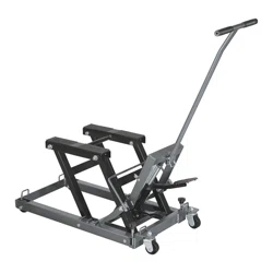
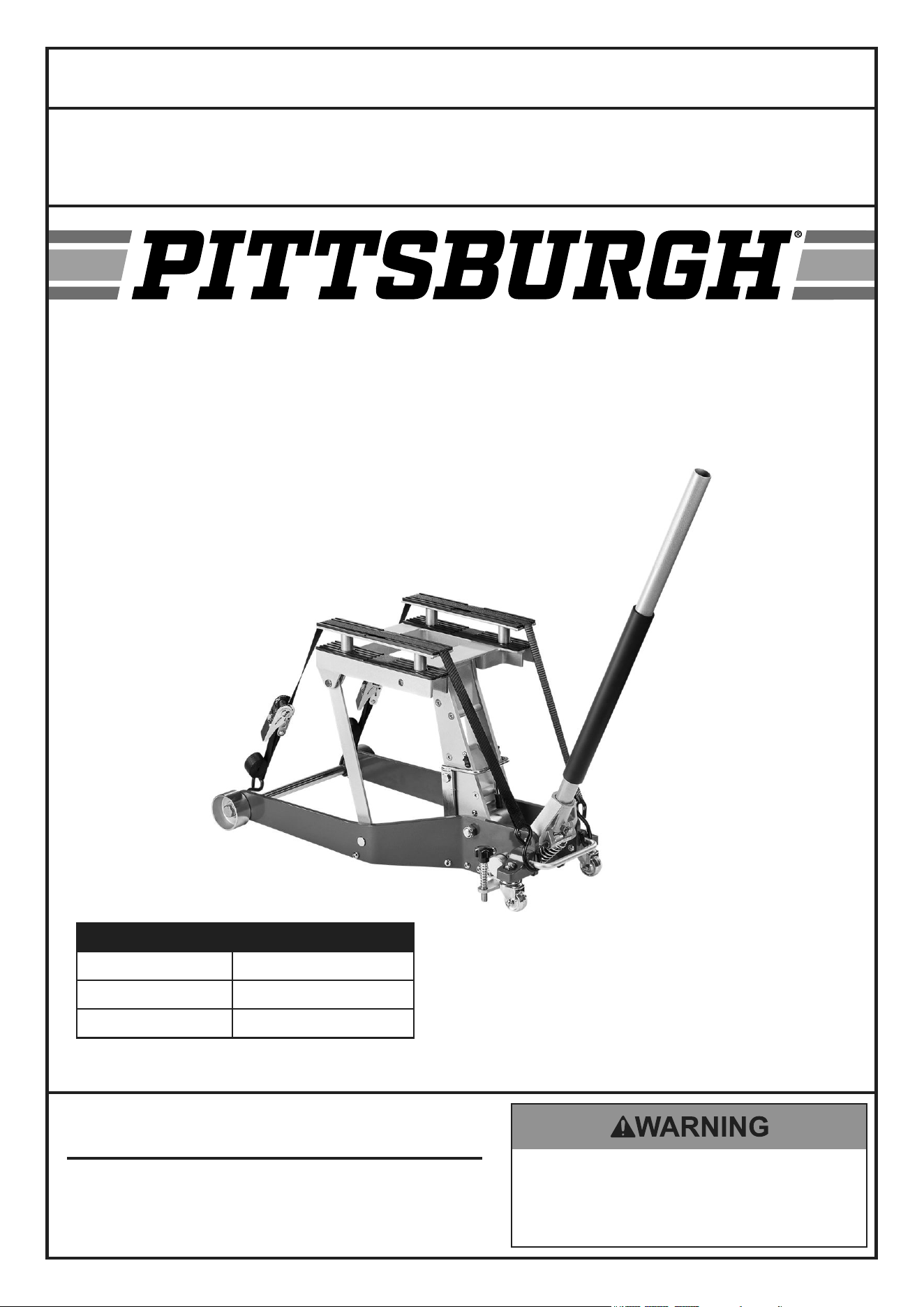
1500 LB. CAPACITY
ATV/MOTORCYCLE LIFT
item 70835
Weight Capacity 1500 lb.
Maximum Height 17-3/4"
Minimum Height 3-3/4"
Owner’s Manual & Safety Instructions
Save This Manual Keep this manual for the safety warnings and precautions, assembly,
operating, inspection, maintenance and cleaning procedures. Write the product’s serial number in the
back of the manual near the assembly diagram (or month and year of purchase if product has no number).
Keep this manual and the receipt in a safe and dry place for future reference. 23j
When unpacking, make sure that the product is intact
and undamaged. If any parts are missing or broken,
please call 1-888-866-5797 as soon as possible.
Copyright
©
2023 by Harbor Freight Tools
®
. All rights reserved.
No portion of this manual or any artwork contained herein may be reproduced in
any shape or form without the express written consent of Harbor Freight Tools.
Diagrams within this manual may not be drawn proportionally. Due to continuing
improvements, actual product may differ slightly from the product described herein.
Tools required for assembly and service may not be included.
read this material before using this product.
Failure to do so can result in serious injury.
SaVe tHiS ManuaL.
Owner’s Manual & Safety Instructions
Save This Manual Keep this manual for the safety warnings and precautions, assembly,
operating, inspection, maintenance and cleaning procedures. Write the product’s serial number in the
back of the manual near the assembly diagram (or month and year of purchase if product has no number).
Keep this manual and the receipt in a safe and dry place for future reference.
When unpacking, make sure that the product is intact
and undamaged. If any parts are missing or broken,
please call 1-888-866-5797 as soon as possible.
Copyright
©
2023 by Harbor Freight Tools
®
. All rights reserved.
No portion of this manual or any artwork contained herein may be reproduced in
any shape or form without the express written consent of Harbor Freight Tools.
Diagrams within this manual may not be drawn proportionally. Due to continuing
improvements, actual product may differ slightly from the product described herein.
Tools required for assembly and service may not be included.
read this material before using this product.
Failure to do so can result in serious injury.
SaVe tHiS ManuaL.
Page 2 For technical questions, please call 1-888-866-5797. 70835
SaFety OperatiOn MaintenanceSetup
table of contents
Important Safety Information ...................... 3
Specifications ............................................. 3
Specifications ............................................. 4
Operation .................................................... 6
Cleaning, Maintenance, and Lubrication .... 8
Troubleshooting .......................................... 9
Parts List and Diagram .............................. 10
Warranty .................................................... 12
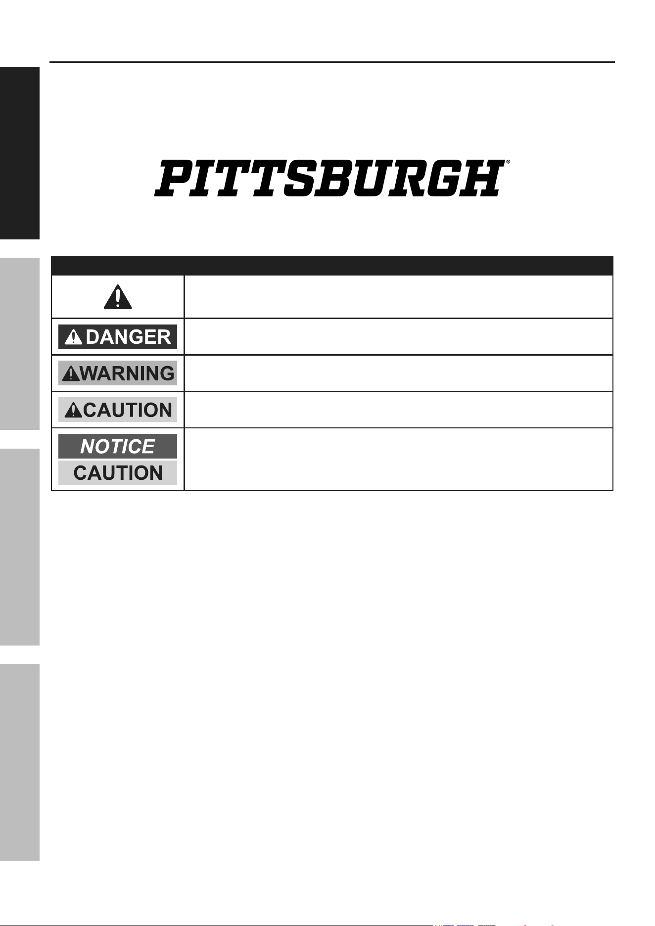
WarninG SyMBOLS anD DeFinitiOnS
This is the safety alert symbol. It is used to alert you to potential
personal injury hazards. Obey all safety messages that
follow this symbol to avoid possible injury or death.
Indicates a hazardous situation which, if not avoided,
will result in death or serious injury.
Indicates a hazardous situation which, if not avoided,
could result in death or serious injury.
Indicates a hazardous situation which, if not avoided,
could result in minor or moderate injury.
Addresses practices not related to personal injury.

Page 3For technical questions, please call 1-888-866-5797.70835
SaFetyOperatiOnMaintenance Setup
iMpOrtant SaFety inFOrMatiOn
1. Study, understand, and follow all instructions
before operating this device.
2. Do not exceed rated capacity.
3. Use only on a hard, level surface
capable of supporting the load.
4. Center load on lift platform.
5. Lift only those areas of the vehicle
specified by its manufacturer.
6. Immediately after lifting load, ensure lift
mechanical load-holding means is engaged.
7. Before moving, lower the load to
the lowest possible point.
8. Secure load with appropriate restraint device.
9. Failure to heed these markings may result in
personal injury and/or property damage.
10. Use of this product is limited to lifting, lowering,
transporting, and storing, in the lowered
position, loads consisting of a single vehicle
whose lift points are compatible with the lift
platform. Incompatibility is evident when the
loaded vehicle wobbles, appears unstable, and/
or does not securely engage the lift platform.
11. Restraining an incompatible load will not make the
load secure and may cause unexpected loss of load.
12. Never work on, around, or under a load
that is not secured and stable.
13. Keep operator’s and bystander’s head,
hands, and feet away from the lift
arms when raising and lowering.
14. No alterations shall be made to this product.
15. Only attachments, restraints, or adapters
supplied by the manufacturer shall be used.
16. Do not adjust safety valve.
17. Wear ANSI-approved safety goggles and
heavy-duty work gloves during use.
18. Lower load slowly.
19. Do not use for aircraft purposes.
20. Inspect before every use; do not use
if parts are loose or damaged.
21. Stay alert. Watch what you are doing, and use
common sense when operating a Lift. Do not use
Lift while tired or under the influence of drugs,
alcohol, or medication. A moment of inattention while
operating lifts may result in serious personal injury
22. Never allow anyone to ride Lift when it is being raised,
lowered, or while holding an ATV or motorcycle.
23. Before use, read manufacturer’s instruction
manual for the ATV or motorcycle being lifted.
24. Store idle Lift out of reach of children and
other untrained persons. Lifts are dangerous
in the hands of untrained users.
25. Lift service must be performed only by qualified repair
personnel. Service or maintenance performed by
unqualified personnel could result in a risk of injury.
26. When servicing the Lift, use only identical
replacement parts - refer to attached, product-
specific parts lists and diagrams. Follow instructions
in the “Maintenance and Servicing” section of this
manual. Use of unauthorized parts or failure to follow
maintenance instructions may create a risk of injury.
27. Maintain labels and nameplates on the Lift. These
carry important information. If unreadable or missing,
contact Harbor Freight Tools for a replacement. The
warnings, precautions, and instructions discussed
in this manual cannot cover all possible conditions
and situations that may occur. The operator
must understand that common sense and
caution are factors, which cannot be built into this
product, but must be supplied by the operator.
SaVe tHeSe inStructiOnS.
Page 4 For technical questions, please call 1-888-866-5797. 70835
SaFety OperatiOn MaintenanceSetup
Specifications
Minimum Saddle Height with Riser 5-3/4"
Maximum Saddle Height with Riser 19-3/4"
Weight Capacity 1500 lb. (dead weight, evenly distributed)
Setup – Before use
read the entire iMpOrtant SaFety inFOrMatiOn section at the beginning of this
manual including all text under subheadings therein before set up or use of this product.
note: For additional information regarding the parts listed in the following pages,
refer to ″Parts List and Diagram″ on page 10.
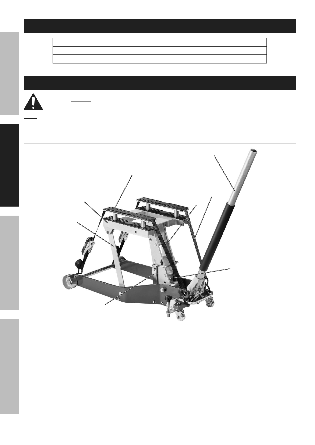
components
Lift arm
Saddle
riser
Handle
Height
Lock Bar
Link Staff
Height
Lock
Handle
tie-Down Strap
Figure a
Page 5For technical questions, please call 1-888-866-5797.70835
SaFetyOperatiOnMaintenance Setup
Lift Setup
1. Loosen the Handle Set Screw (48) located on
Handle Socket (50) (turn counterclockwise).
Insert the Handle (51) into the Handle
Socket. See Figure B: Handle Set-up.
2. Tighten the Handle Set Screw
(turn clockwise) securely.
Handle Handle
Socket (50)Socket (50)
Handle Set Handle Set
Screw (48)Screw (48)
Handle (51)Handle (51)
Figure B: Handle Set-up
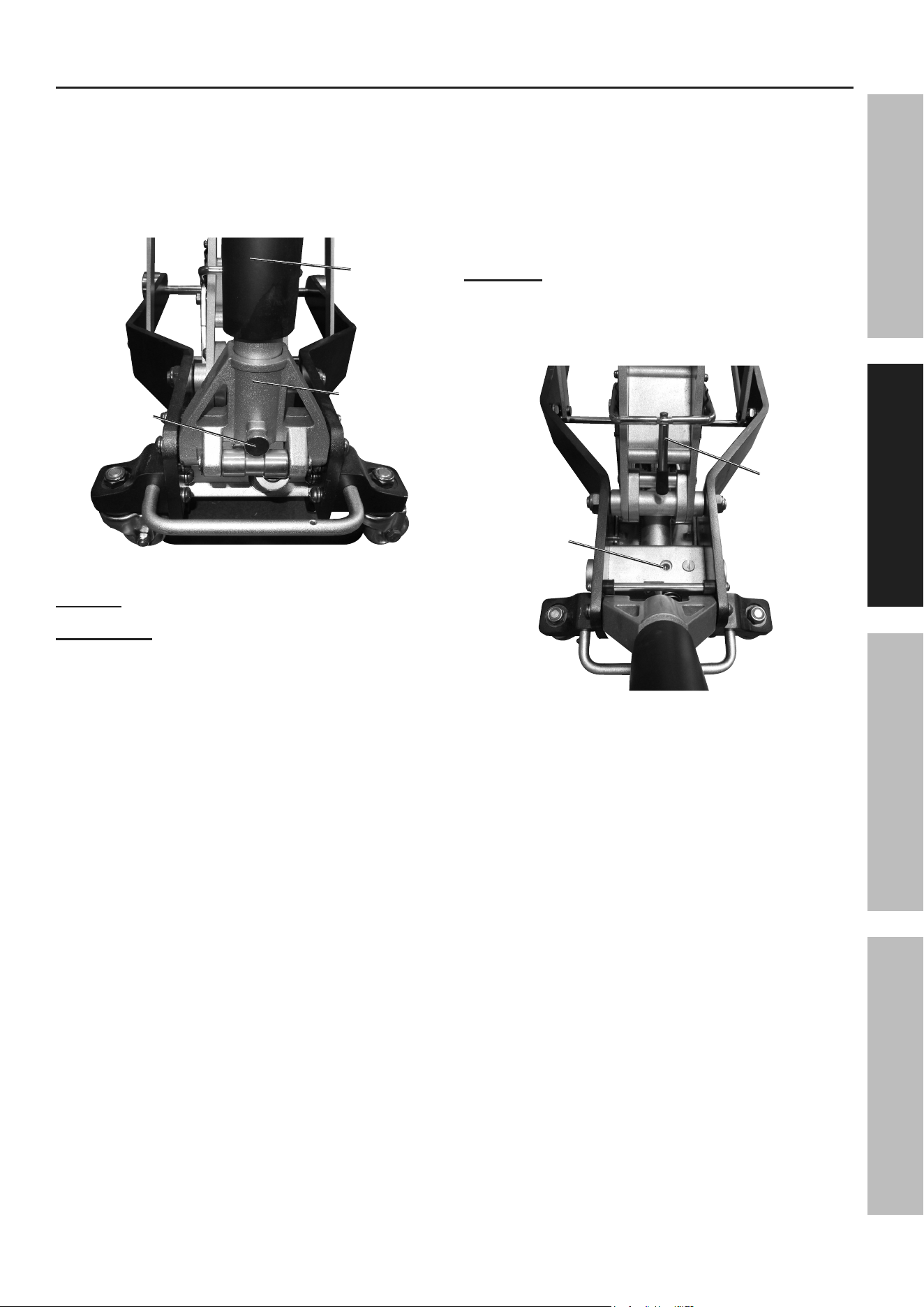
Bleeding
iMpOrtant! Before first use, check for
proper hydraulic oil level in the Hydraulic Power
Unit (36). Thoroughly test the Lift for proper
operation prior to its actual use. If the Lift appears
not to be working properly, it may be necessary
to bleed its hydraulic system of excess air.
3. Turn the Handle (51) counterclockwise
to open the Release Valve.
4. Pump the Handle quickly several times
to purge air from the system.
5. Turn the Handle clockwise to
close the Release Valve.
6. Test the Lift several times for proper operation
before attempting to lift a load. If, after bleeding,
the Lift still does not appear to be working
properly, do not use the Lift until it has been
repaired by a qualified service technician.
adding Oil
1. Remove the Oil Fill Screw on the
top of the Hydraulic Power Unit (36).
See Figure c: Oil Fill Screw.
Oil Fill Oil Fill
ScrewScrew
Height Height
Lock Lock
HandleHandle
Figure c: Oil Fill Screw
2. Add high grade hydraulic oil (sold separately)
into the oil fill hole slowly until the oil
reaches the bottom of the threads.
3. Replace the Oil Fill Screw.
Page 6 For technical questions, please call 1-888-866-5797. 70835
SaFety OperatiOn MaintenanceSetup
Operation
tO preVent SeriOuS inJury: Do not work on the Lift, or leave it unattended if
the Lock Bar is not in position. Keep clear of Lift arms during operation.
Lifting
1. Use the Handle to roll the Lift into position.
Lower the Lift by turning
the Handle counterclockwise.
2. Roll the Lift under the load. (See vehicle owner’s
manual for recommended lift points.) Align the
Saddle under the vehicle base frame.
WarninG! tO preVent SeriOuS inJury: If the
vehicle base frame cannot sit flatly on the Saddle, do not
use this Lift.
The vehicle could fall over.
3. Turn the Handle completely clockwise.
Then pump the Handle up and down to raise the lift.
4. Continue to pump the Handle up and down until
the Saddle just touches the load. Make sure the
load is centered and balanced on the Saddle.
If the load is not evenly distributed on the Saddle
it may fall from the lift, causing serious injury.
5. Use Tie-Down Strap(s) (60) to secure the load.
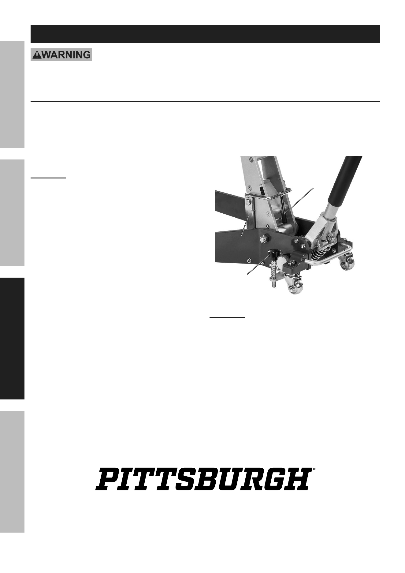
6. Continue to raise the Lift to the desired height.
Install Risers before operating the lift
when more lift is needed. Height Lock
Bar will click into a supporting position.
See Figure D: Height Lock Bar.
Height Height
Lock Lock
HandleHandle
Height Height
Lock BarLock Bar
Star Grip Star Grip
KnobKnob
Figure D: Height Lock Bar
WarninG! Not engaging the Height Lock Bar may
result in serious injury or death, and damage the Lift.
7. Stabilize loaded jack on hard surface
by adjusting Star Grip Knob (57).

Page 7For technical questions, please call 1-888-866-5797.70835
SaFetyOperatiOnMaintenance Setup
Lowering
1. Carefully remove all tools, parts, etc.
from under the lift.
2. First raise the Lift slightly by pumping the Handle
to relieve pressure on the Height Lock Bar. Lift
Height Lock Handle out of locked position.
3. Turn the Handle counterclockwise slowly in
extremely small increments. Never allow the load
to come down quickly or suddenly. Have another
person balance the vehicle during this process.
4. Once the load is on the ground,
remove the tie-down straps.
5. Release Star Grip Knob(s).
Roll the Lift out from under the load.
6. Clean external surfaces of the Lift with
a clean, dry cloth. Turn the Handle completely
counterclockwise. Store the Lift in a dry,
indoor area out of reach of children.

Page 8 For technical questions, please call 1-888-866-5797. 70835
SaFety OperatiOn MaintenanceSetup
cleaning, Maintenance, and Lubrication
procedures not specifically explained in this manual must
be performed only by a qualified technician.
tO preVent SeriOuS inJury FrOM tOOL FaiLure: Do not use damaged equipment.
if abnormal noise or vibration occurs, have the problem corrected before further use.
1. Before each use, inspect the general condition of
the Lift. Check for broken, cracked, or bent parts,
loose or missing parts, and any condition that may
affect the proper operation of the product. If a
problem occurs, have the problem corrected before
further use. Do not use damaged equipment.
2. Before each use, thoroughly test the Lift
for proper operation prior to its actual use.
If the Lift appears not to be working
properly, follow Bleeding on page 5.
3. Change the hydraulic oil at least
once every three years:
a. With the Lift fully lowered, remove the Oil Fill
Screw on the side of the Cylinder Assembly.
b. With assistance, place the Lift on its side to allow
the old hydraulic oil to drain out of the jack’s Oil
Reservoir completely, and dispose of the old
hydraulic oil in accordance with local regulations.
c. With the Lift upright, completely fill the
jack’s Oil Reservoir with a high quality
hydraulic oil (sold separately) until the oil
just begins to run out of the oil fill hole.
d. Reinstall the Oil Fill Screw.
4. Wipe dry with a clean cloth. Then, store the
Lift in a safe, dry location out of reach of
children and other non-authorized people.

Page 9For technical questions, please call 1-888-866-5797.70835
SaFetyOperatiOnMaintenance Setup
troubleshooting
tO preVent SeriOuS inJury: use caution when troubleshooting a malfunctioning lift.
Stay well clear of the supported load. completely resolve all problems before use.
If the solutions presented in the Troubleshooting guide do not solve the problem, have a qualified technician inspect
and repair the Lift before use. after the Lift is repaired: test it carefully without a load by raising it and
lowering it fully, checking for proper operation, BeFOre returninG tHe LiFt tO OperatiOn.
DO nOt uSe a DaMaGeD Or MaLFunctiOninG LiFt!
pOSSiBLe SyMptOMS prOBaBLe SOLutiOn
(Make certain that the
lift is not supporting a
load while attempting
a solution.)
unit will not lift
at its weight
capacity
Saddle
lowers
under load
Saddle
will not lift
all the way
Oil leaking
from filler
plug
X X
Turn Handle completely
clockwise.
Turn Bleed Screw completely
clockwise to close.
X X
Jack may be low on oil.
Check the oil level and refill
or replace if needed.
Bleed Air from the Cylinder
Assembly (Hydraulic System).
X
Unit may have too much
hydraulic oil inside.
Check fluid level and
adjust if needed.
Page 10 For technical questions, please call 1-888-866-5797. 70835
SaFety OperatiOn MaintenanceSetup
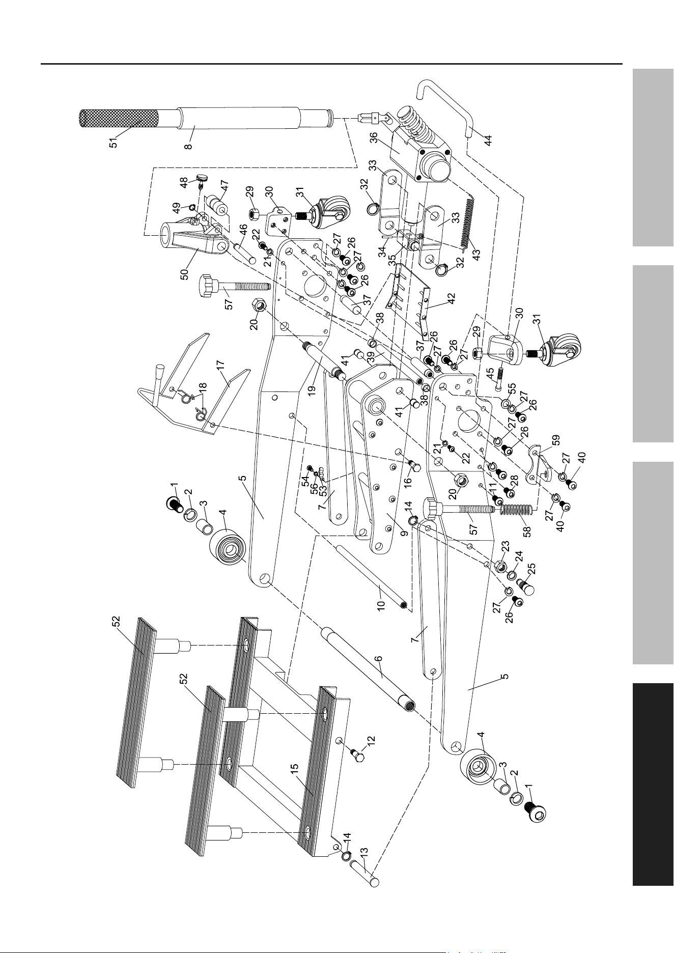
part Description Qty
1 Bolt 2
2 Washer 18 2
3 Bushing 2
4 Front Wheel 2
5 Side Plate 2
6 Front Wheel Axle 1
7 Radius Linkage 2
8 Handle Bumper 1
9 Lift Arm 1
10 Rod 1
11 Bolt 8X20 2
12 Pin 2
13 Linkage Axle 2
14 Spring Washer 13 4
15 Lifting Frame 1
16 Bolt 2
17 Height Lock Bar 1
18 Lock Spring 2
19 Lift Arm Axle 1
20 Lock Nut M16 2
21 Washer 6 2
22 Bolt M6x25 2
23 Nut M16 2
24 Washer 16 2
25 Bolt 2
26 Bolt M8x25 17
27 Spring Washer 8 17
28 Bolt 8X16 6
29 Lock Nut M12 2
30 Rear Caster Bracket 2
part Description Qty
31 Rear Caster Assy 2
32 Washer 19 2
33 Short Linkage 2
34 Spring Pin 4X26 1
35 Rod 1
36 Hydraulic Power Unit 1
37 Pump Roller Axle 2
38 Rubber Guard 2
39 Rod 1
40 Bolt M8x30 2
41 Linkage Axle Bolt 2
42 Ratchet Support Plate 1
43 Lift Arm Return Spring 2
44 Rear Handle 1
45 Bolt M8x35 2
46 Roller Rod 1
47 Roller 1
48 Handle Set Screw 1
49 Retaining Ring 1
50 Handle Socket 1
51 Handle 1
52 Risers 2
53 Retaining Ring 1
54 Bolt M5x10 2
55 Washer 8 2
56 Spring Washer 5 2
57 Star Grip Knob 2
58 Star Grip Knob Spring 2
59 Star Grip Knob Base 2
60 Tie-Down Strap (Not Shown) 2
parts List and Diagram
pLeaSe reaD tHe FOLLOWinG careFuLLy
THE MANUFACTURER AND/OR DISTRIBUTOR HAS PROVIDED THE PARTS LIST AND ASSEMBLY DIAGRAM
IN THIS MANUAL AS A REFERENCE TOOL ONLY. NEITHER THE MANUFACTURER OR DISTRIBUTOR
MAKES ANY REPRESENTATION OR WARRANTY OF ANY KIND TO THE BUYER THAT HE OR SHE IS
QUALIFIED TO MAKE ANY REPAIRS TO THE PRODUCT, OR THAT HE OR SHE IS QUALIFIED TO REPLACE
ANY PARTS OF THE PRODUCT. IN FACT, THE MANUFACTURER AND/OR DISTRIBUTOR EXPRESSLY
STATES THAT ALL REPAIRS AND PARTS REPLACEMENTS SHOULD BE UNDERTAKEN BY CERTIFIED AND
LICENSED TECHNICIANS, AND NOT BY THE BUYER. THE BUYER ASSUMES ALL RISK AND LIABILITY
ARISING OUT OF HIS OR HER REPAIRS TO THE ORIGINAL PRODUCT OR REPLACEMENT PARTS
THERETO, OR ARISING OUT OF HIS OR HER INSTALLATION OF REPLACEMENT PARTS THERETO.
parts List
record product's Serial number Here:
note: If product has no serial number, record month and year of purchase instead.
note: Some parts are listed and shown for illustration purposes only, and are not available
individually as replacement parts. Specify UPC 193175515162 when ordering parts.
Page 11For technical questions, please call 1-888-866-5797.70835
SaFetyOperatiOnMaintenance Setup
assembly Diagram
Tie-Down Strap (60) Not Shown

Limited 90 Day Warranty
Harbor Freight Tools Co. makes every effort to assure that its products meet high quality and durability standards,
and warrants to the original purchaser that this product is free from defects in materials and workmanship for the
period of 90 days from the date of purchase. This warranty does not apply to damage due directly or indirectly,
to misuse, abuse, negligence or accidents, repairs or alterations outside our facilities, criminal activity, improper
installation, normal wear and tear, or to lack of maintenance. We shall in no event be liable for death, injuries
to persons or property, or for incidental, contingent, special or consequential damages arising from the use of
our product. Some states do not allow the exclusion or limitation of incidental or consequential damages, so the
above limitation of exclusion may not apply to you. THIS WARRANTY IS EXPRESSLY IN LIEU OF ALL OTHER
WARRANTIES, EXPRESS OR IMPLIED, INCLUDING THE WARRANTIES OF MERCHANTABILITY AND FITNESS.
To take advantage of this warranty, the product or part must be returned to us with transportation charges
prepaid. Proof of purchase date and an explanation of the complaint must accompany the merchandise.
If our inspection verifies the defect, we will either repair or replace the product at our election or we may
elect to refund the purchase price if we cannot readily and quickly provide you with a replacement. We will
return repaired products at our expense, but if we determine there is no defect, or that the defect resulted
from causes not within the scope of our warranty, then you must bear the cost of returning the product.
This warranty gives you specific legal rights and you may also have other rights which vary from state to state.
26677 agoura road • calabasas, ca 91302 • 1-888-866-5797