CAUTION:
Weight on this product should not exceed 300 lbs.
Product May Vary Slightly From Pictured.
STAMINA PRODUCTS
MADE IN CHINA
© 2023 Stamina Products, Inc.
2023, 10
This Product is Distributed Exclusively by
2040 N Alliance Ave, Springeld, MO 65803
Customer Care
1 (800) 375-7520
www.staminaproducts.com
When calling for parts or
service, please specify
the following numbers
:
Model#: 35-1423D
S/N: _____________
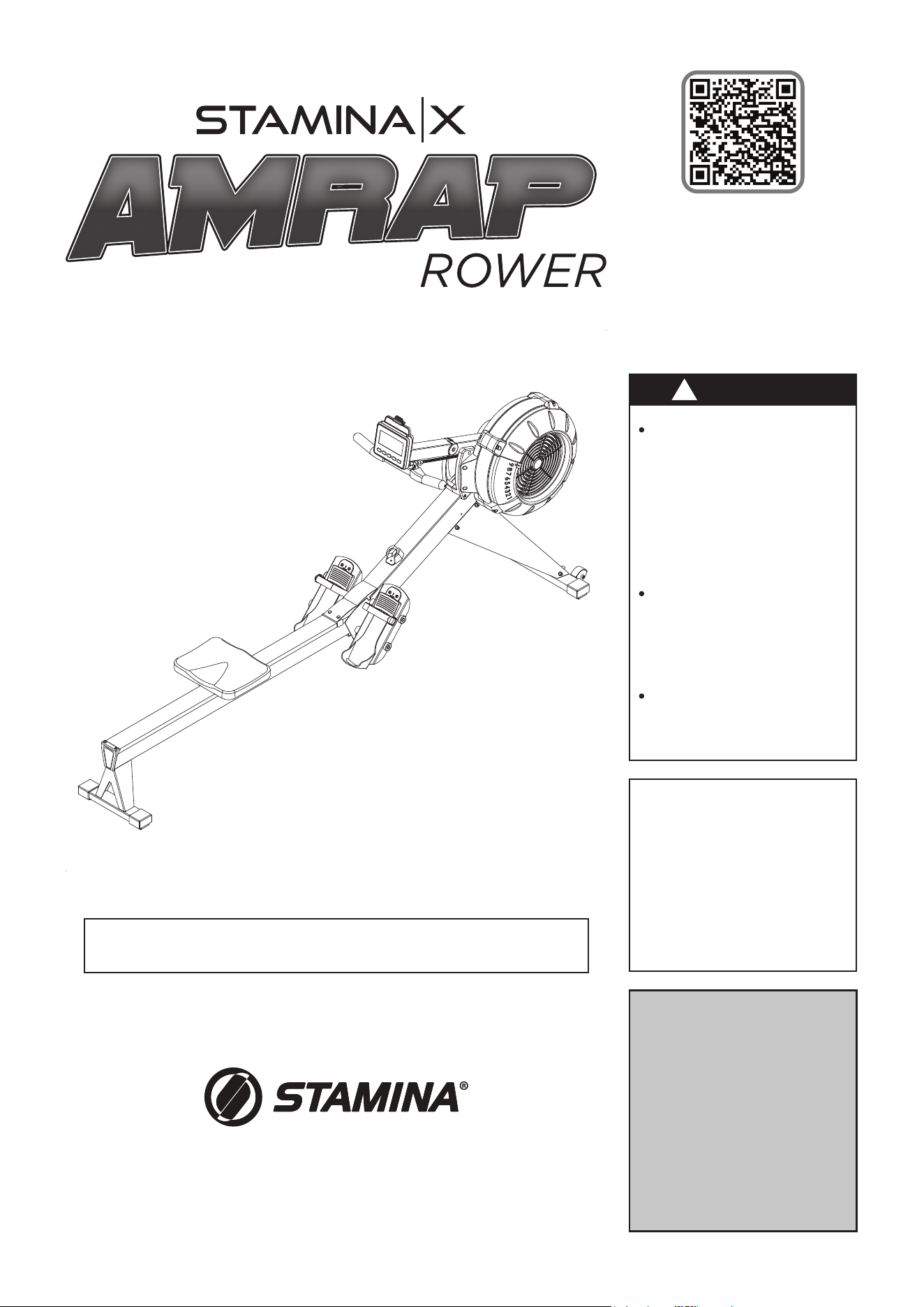
Owner's
Manual
Download the müüv app
for a step-by-step assembly video
Exercise can present
a health risk. Consult
a physician before
beginning any exercise
program with this
equipment. If you feel
faint or dizzy, immediately
discontinue use.
Serious bodily injury can
occur if this equipment is
not assembled and used
in accordance with the
owner’s manual.
Follow all safety
instructions in this
owner’s
manual.
!
WARNING

Quickstart Guide
Go to the App Store on your device or
scan the QR Code for quick access.
Smart Audio Workouts for Your Rower
Download the app and get moving!
Assembly video included in app.
IMPORTANT
Apple, the Apple logo, iPhone, and iPod touch are trademarks of Apple Inc., registered in the U.S. and other countries. App Store is a service
mark of Apple Inc., registered in the U.S. and other countries. Google Play and the Google Play logo are trademarks of Google LLC.

3
TABLE OF CONTENTS
Safety Instructions ...................................... 3
Before You Begin ........................................ 5
Equipment Warning, Caution & Notice Labels
... 6
Hardware Identication Chart .................... 7
Assembly Instructions ................................ 8
Computer Instructions .............................. 12
Operational Instructions ........................... 20
Storage ....................................................... 22
Maintenance ............................................... 23
Conditioning Guidelines ........................... 25
Warm-Up and Cool-Down ......................... 26
Warranty ..................................................... 27
Product Parts Drawing .............................. 28
Parts List .................................................... 29
Fax/Mail Ordering Form ............................ 33
SAFETY INSTRUCTIONS
!
WARNING
Cancer and Reproductive Harm www.P65Warnings.ca.gov
Consult your physician before starting this or any exercise program. This is
especially important if you are over the age of 35, have never exercised before,
are pregnant, or suer from any health problem. This product is for home use
only. Do not use in institutional or commercial applications. Failure to follow all
warnings and instructions could result in serious injury or death.
To reduce the risk of serious injury, read the following Safety Instructions
before using the STAMINA│X AMRAP ROWER.
!
WARNING
!
WARNING
The
STAMINA│X AMRAP ROWER
should only be used after a thorough review of the Owner’s
Manual by all exercisers and saved for future reference.
Make sure that the product is properly assembled and tightened before use.
We recommend that two people be available for assembly of this product.
Keep children and pets away from the
STAMINA│X AMRAP ROWER
at all times. This product is for
adult use only.
It is recommended that you place this product on an equipment mat.
Set up and operate the
STAMINA│X AMRAP ROWER
on a solid level surface. Do not position the
product on loose or uneven surfaces.
Make sure that adequate space is available for access to and around the STAMINA│X AMRAP ROWER.
Keep ngers clear of all pinch points when folding and unfolding the
STAMINA│X AMRAP ROWER
.
Before using, always inspect the product for worn parts that should be replaced or loose parts that
should be tightened.
Before using, check the condition of the CHAIN(36). Replace the CHAIN(36) if it is cracked or broken.
Do not use the SEAT(51) to move the STAMINA│X AMRAP ROWER. The SEAT(51) will move and the
SEAT CARRIAGE(10) may pinch your hand or ngers. When assembling or separating the unit, keep all
children away and make sure your hands are clear of any pinch point.
Always choose the workout which best ts your physical strength and exibility level. Know your
limits and train within them.
Do not wear loose clothing while using the
STAMINA│X AMRAP ROWER
.
Always wear proper footwear such as running, walking, or cross training shoes.
Be careful to maintain your balance while assembling, mounting, using and dismounting the
STAMINA│X AMRAP ROWER
. Loss of balance may result in a fall or serious bodily injury.
The
STAMINA│X AMRAP ROWER
should not be used by persons weighing over 250 pounds.
The
STAMINA│X AMRAP ROWER
is for consumer use only. It is not for use in public or semipublic
facilities.

NEED HELP?
CONTACT US FIRST
1 (800) 375-7520
customer.care@staminaproducts.com
Hi! From all of us here at Stamina Products, thank you for your purchase. We
know that you have big fitness goals in mind and we are here to help you along.
Call us, email us, or send us a message on Facebook. Be sure to contact us if you
have any questions on your new product. We look forward to hearing from you!
With your body in mind,
Stamina Customer Care
To enact your extended warranty and to help us better
serve you, please go online and register your new product.
register.staminaproducts.com
ONLINE
customer.car[email protected]om
www.staminaproducts.com
TELEPHONE
1 (800) 375-7520
FAX
(417) 889-8064
MAIL
Stamina Products, Inc.
ATTN: Customer Care
2040 N Alliance Ave
Springfield, MO 65803
facebook.com/StaminaProducts
facebook.com/AeroPilates
CUSTOMER CARE HOURS:
Monday-Thursday, 7:30 AM-5:00 PM, Central Time
Friday, 8:00 AM-3:00 PM, Central Time
It is quick and easy to register online, but if you’re a little old school or just need a
reason to raise that little flag on your mailbox, fill out the info on the last page of this
manual and mail it in.
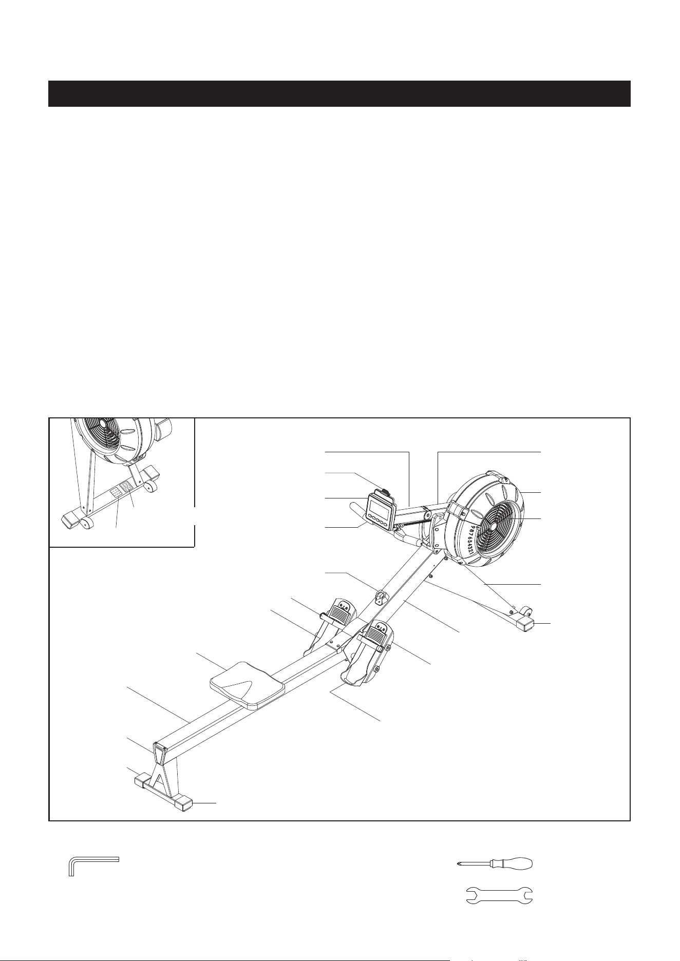
BEFORE YOU BEGIN
5
Rail Frame
Seat
Pedal Cap
Handlebar
Handlebar Holder
Rail Cap
Pedal Cap
Right
Fan Cage
Computer
Pedal Strap
Main Frame
Endcap
Endcap
Endcap
Damper
Right
Support Leg
Pedal Support
Phone Clamp
Computer Post
THE FOLLOWING TOOLS ARE INCLUDED FOR ASSEMBLY :
Allen Wrench (6mm)
(2 pieces)
Screwdriver
Wrench
Thank you for choosing the
STAMINA│X AMRAP
ROWER
. We take great pride in this quality product
and hope it will provide many hours of quality
exercise to make you feel better, look better, and
enjoy life to its fullest.
It's a proven fact that a regular exercise program
can improve your physical and mental health.
Too often, our busy lifestyles limit our time and
opportunity to exercise. The
STAMINA│X AMRAP
ROWER
provides a convenient and simple method
to begin your journey of getting your body in shape
and achieving a happier and healthier lifestyle.
Before reading further, please review the
drawing below and familiarize yourself with the
parts that are labeled. Locate the serial decal on
the product and write the serial number on the
cover of the manual in the space provided. See the
next page for an image of the serial decal. Model
number and serial number are required when
calling for assistance.
Read this manual carefully before using the
STAMINA│X AMRAP ROWER
.
Providing you with a quality product is Stamina's
top priority. However, sometimes there could be a
missing or incorrectly sized part. If you have any
questions or problems with the parts included with
your
STAMINA│X AMRAP ROWER
, please do not
return the product. Contact us FIRST!
If a part is missing or defective, please contact
Customer Care for assistance. Call us toll free
at 1-800-375-7520 (in the U.S.) or live chat on
staminaproducts.com. Our Customer Care Sta is
available to assist you from 7:30 A.M. to 5:00 P.M.
(Central Time) Monday through Thursday and 8:00
A.M. to 3:00 P.M. (Central Time) on Friday.
Be sure to have the name and model number of
the product available when you contact us.
Caution Label
Serial Decal
Extension
Post
6
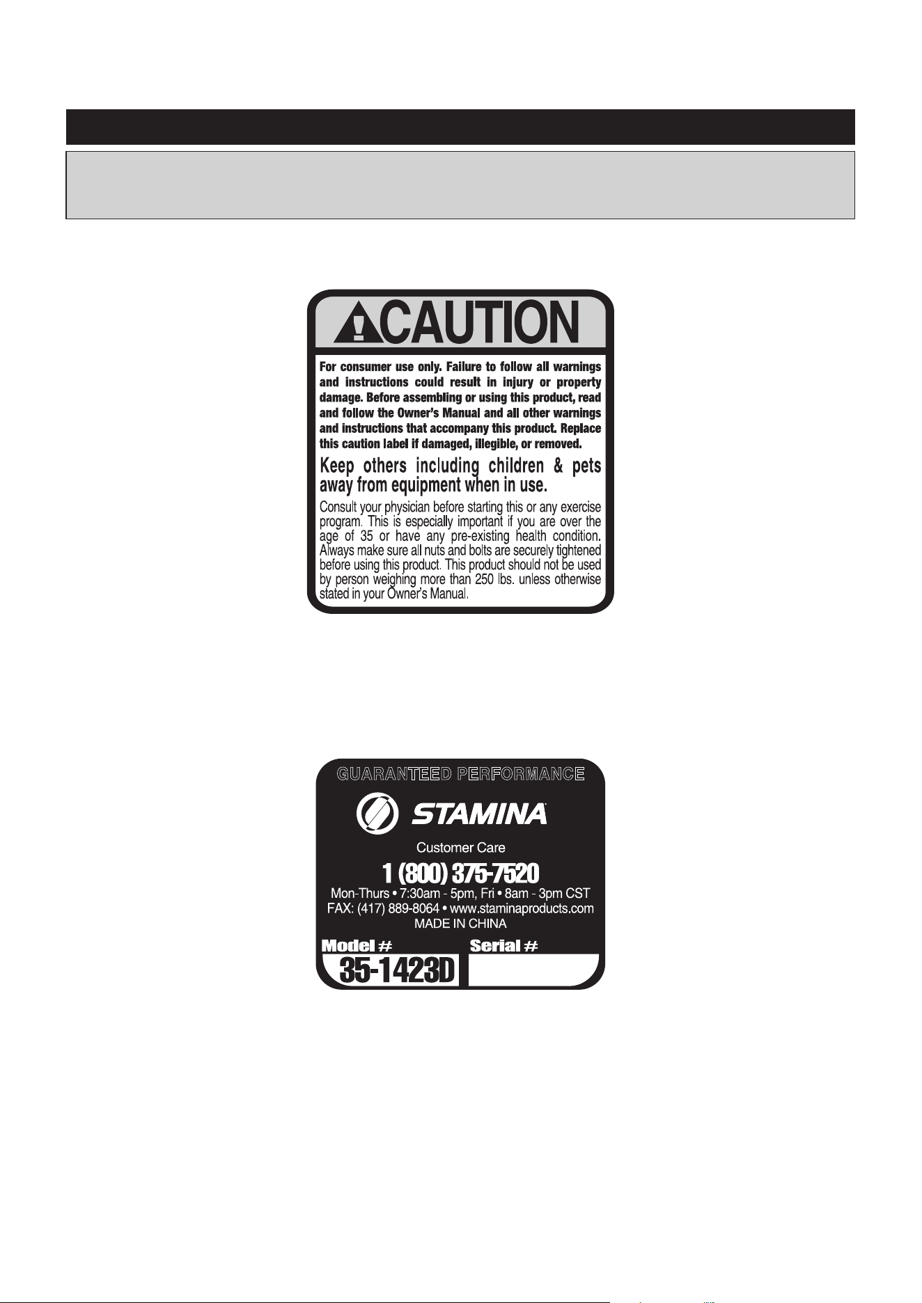
This chart is provided to help identify the warning, caution, and notice labels on the STAMINA│X
AMRAP ROWER. Please take a moment to familiarize yourself with all of the warning, caution, and
notice labels.
EQUIPMENT WARNING, CAUTION & NOTICE LABELS
To best serve you, our Customer Care Representatives will
need your serial number. For quick access, write in your
serial number on the cover of the manual.
SERIAL DECAL(129)
CAUTION LABEL(115)
Part Number and Description Qty
7
length
length
mm.
in.
INCHES
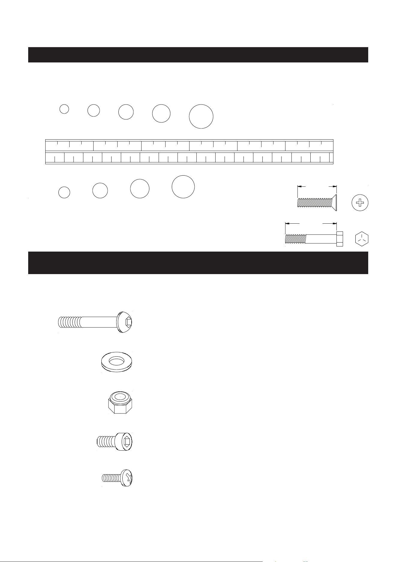
This chart is provided to help identify the fasteners used in the assembly process. Place the washers or
the ends of the bolts or screws on the circles to check for the correct diameter. Use the small scale to
check the length of the bolts and screws.
NOTICE: The length of all bolts and screws, except those with flat
heads, is measured from below the head to the end of the bolt
or screw. Flat head bolts and screws are measured from the
top of the head to the end of the bolt or screw.
After unpacking the unit, open the hardware bag and make sure that you have all the following
fasteners. Some fasteners may be already attached to the parts.
MILLIMETERS
0 10 20 30 40 50 60 70 80 90
100
110
120
130 140
150
0 1/2
1 1/2
2 1/2
3 1/2
4 1/2
5 1/2
6
6 8
10
12
3/16"
1/4"
5/16" 3/8" 1/2"
HARDWARE IDENTIFICATION CHART
79 Washer (M8) 9
81 Bolt, Socket Head (M8 x 1.25 x 12mm) 8
173 Bolt, Socket Head (M8 x 1.25 x 20mm) 4
141 Bolt, Round Head (M6 x 1 x 12mm) 2
80 Nylock Nut (M8 x 1.25) 1
78 Bolt, Button Head (M8 x 1.25 x 75mm) 1
8
ASSEMBLY INSTRUCTIONS
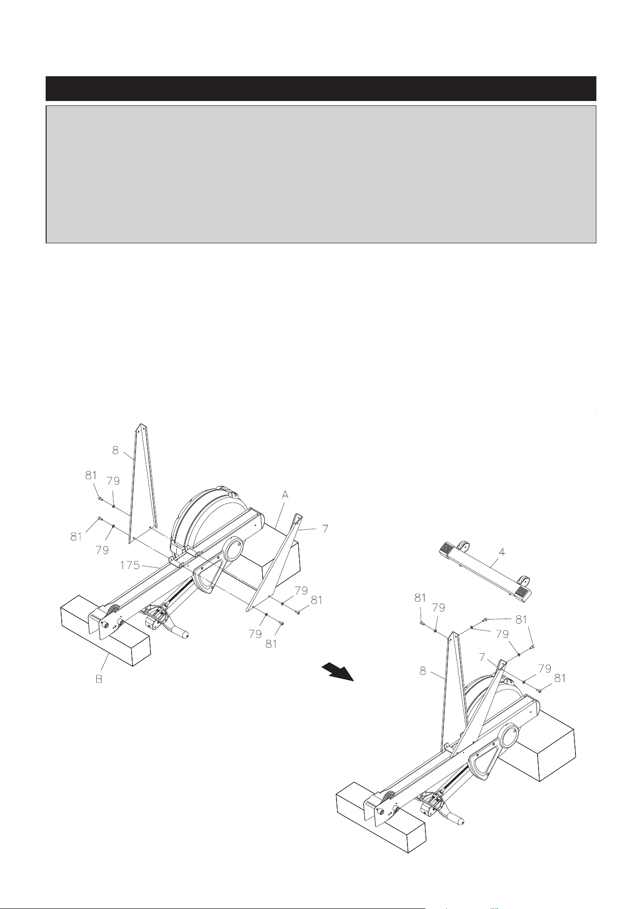
STEP 1
Refer to illustration 1. Turn the main assembly of the
STAMINA│X AMRAP ROWER upside down
and place
it in the packing material styrofoam(A) and (B) to avoid breaking the chain covers. Attach the LEFT and
RIGHT SUPPORT LEGS(7, 8) to the MAIN FRAME(175) with SOCKET HEAD BOLTS(M8x1.25x12mm)
(81) and WASHERS(M8)(79). Do not tighten all bolts until Step 2.
STEP 2
Refer to illustration 2. Attach the FRONT STABILIZER(4) to the LEFT and RIGHT SUPPORT LEGS
(7, 8) with SOCKET HEAD BOLTS(M8x1.25x12mm)(81) and WASHERS(M8)(79). Then tighten all bolts.
Turn the assembly over.
1.
2.
Place all parts from the box in a cleared area and position them on the oor in front of you. Remove
all packing materials from your area and place them back into the box. Do not dispose of the packing
materials until assembly is completed. Read each step carefully before beginning. If you are missing
a part, please go to staminaproducts.com under the Customer Care section and order the part
needed, e-mail us at customer[email protected], or call us toll free at 1-800-375-7520
(in the U.S.). Our Customer Care Sta is available to assist you from 7:30 A.M. to 5:00 P.M. (Central
Time) Monday through Thursday and 8:00 A.M. to 3:00 P.M. (Central Time) on Friday.
Some product parts are t tested at the factory to ensure proper t and alignment. Marks in
the paint may be noticeable, but are not an indication of damage.
ASSEMBLY INSTRUCTIONS
9
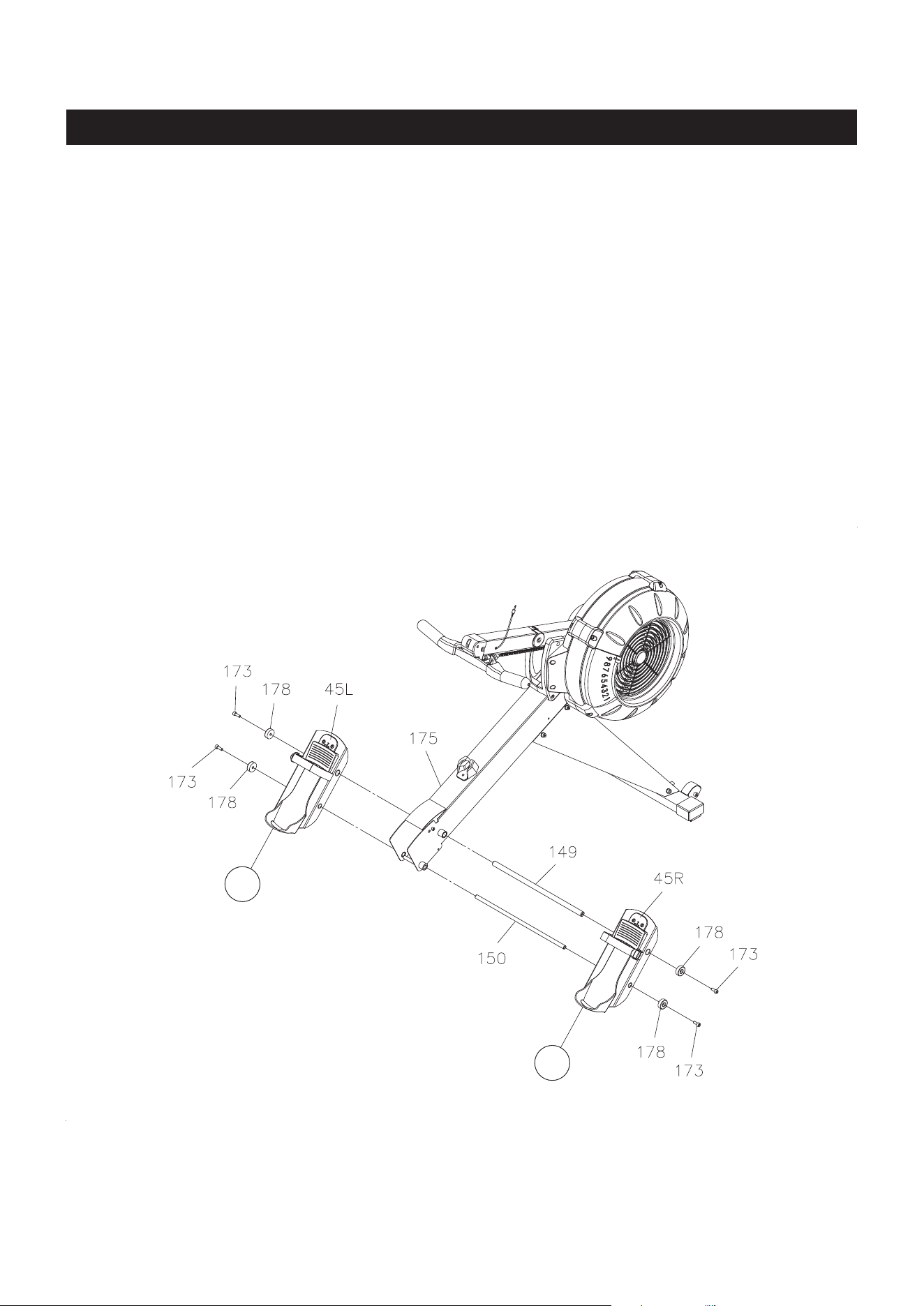
STEP 3
NOTE: You need to use two Allen Wrenches to tighten the SOCKET HEAD BOLTS(M8x1.25x20mm)(173)
at both ends of the PEDAL SHAFTS(149, 150) at the same time.
There is an “L” decal on the left PEDAL CAP(45L), and an “R” decal on the right PEDAL CAP(45R).
Insert the LARGE PEDAL SHAFT(149) through the upper hole located on the MAIN FRAME(175). Place
the left PEDAL CAP(45L) onto left end, and place the right PEDAL CAP(45R) onto right end of the LARGE
PEDAL SHAFT(149), slide them toward the MAIN FRAME(175). Then secure the PEDAL CAPS(45L,
45R) with SOCKET HEAD BOLTS(M8x1.25x20mm)(173) and SECURING CAPS(178) at both ends of
the LARGE PEDAL SHAFT(149).
Insert the PEDAL SHAFT(150) through the holes on the PEDAL CAPS(45L, 45R) and the MAIN
FRAME(175). Then secure the PEDAL CAPS(45L, 45R) with SOCKET HEAD BOLTS(M8x1.25x20mm)
(173) and SECURING CAPS(178) at both ends of the PEDAL SHAFT(150).
R
L
ASSEMBLY INSTRUCTIONS
10
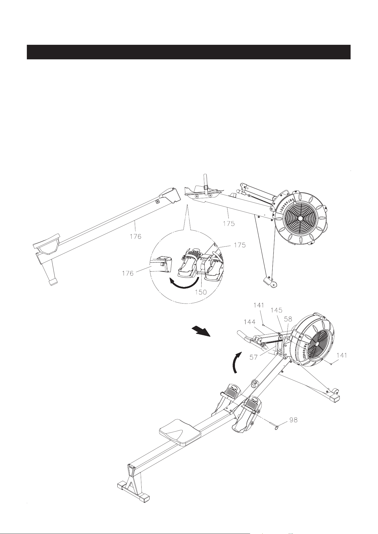
STEP 4
Refer to illustration 3. Lift up the MAIN FRAME(175) and RAIL FRAME(176) to insert the RAIL FRAME(176)
into the MAIN FRAME(175). Make the PEDAL SHAFT(150) on the MAIN FRAME(175) t into the gap in
the RAIL FRAME(176). Then put the MAIN FRAME(175) and RAIL FRAME(176) down. Refer to illustration
4. Lock the MAIN FRAME(175) and RAIL FRAME(176) together with the PULL PIN(98).
STEP 5
Refer to illustration 4. Swing up the COMPUTER POST(144) and EXTENSION POST(145) assembly.
Attach the EXTENSION POST(145) to the LEFT and RIGHT COVERS(57, 58) with ROUND HEAD BOLTS
(M6x1x12mm)(141).
3.
4.
ASSEMBLY INSTRUCTIONS
11
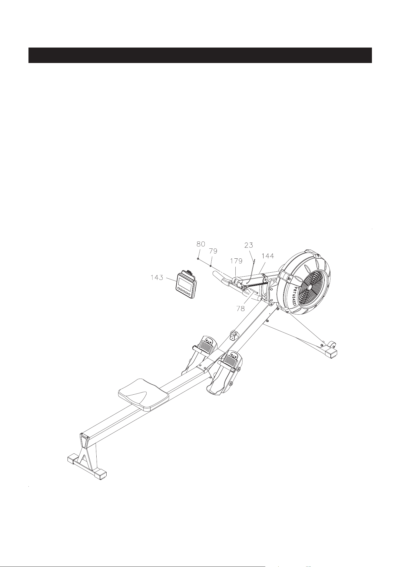
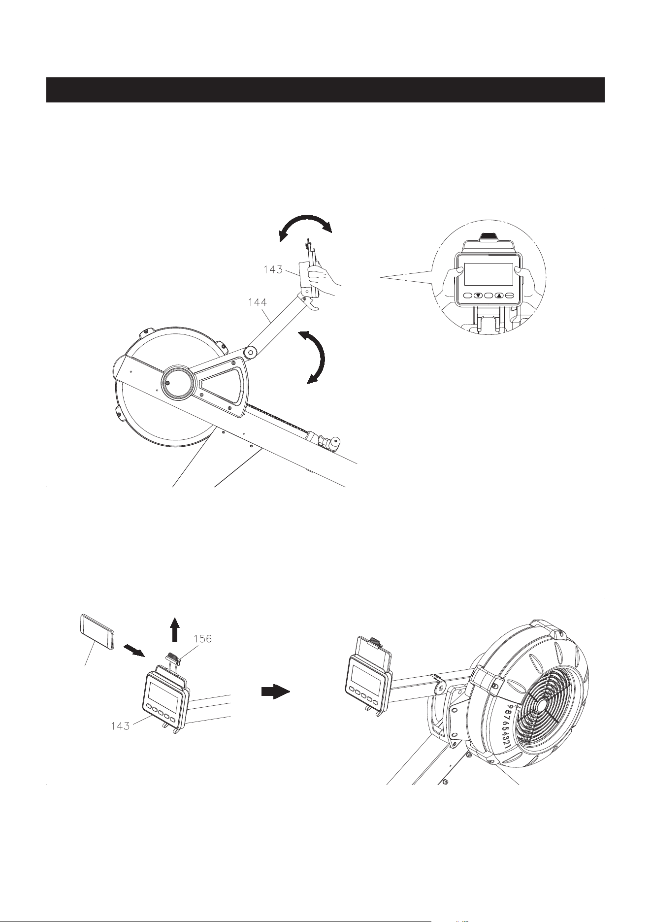
STEP 6
Install two size C batteries into the COMPUTER(143), the batteries are not included. See page 19 for
detailed battery installation instructions. Attach the COMPUTER(143) to the COMPUTER POST(144) with
BUTTON HEAD BOLT(M8x1.25x75mm)(78), WASHER(M8)(79), and NYLOCK NUT(M8x1.25)(80). Plug
the SENSOR WIRE(23) into the back of the COMPUTER(143).
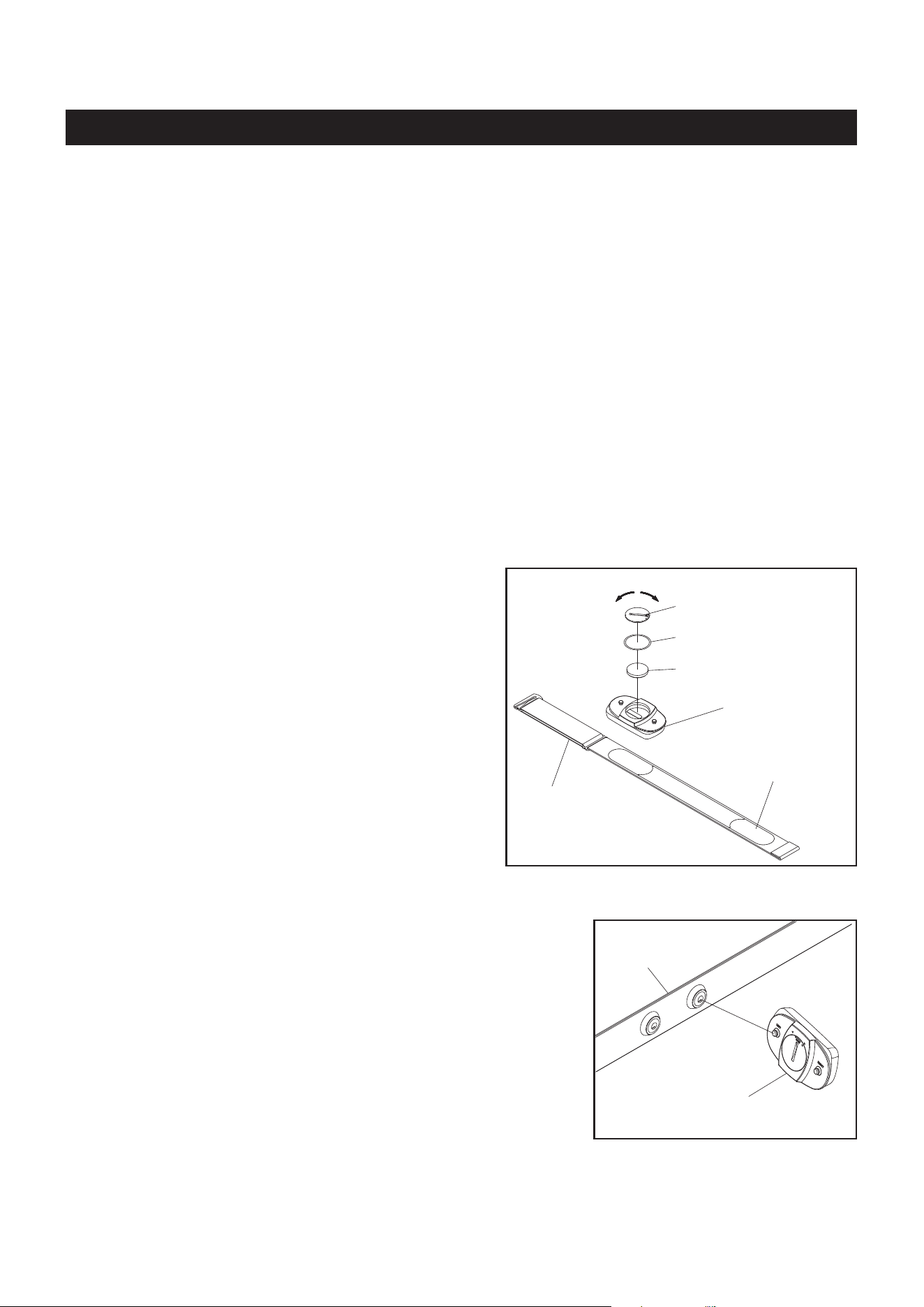
To assemble the HEART RATE TRANSMITTER(116),
insert the BUTTON BATTERY(CR2032)(120) as shown
in the illustration. Place the BATTERY RUBBER
RING(118) on the edge of the opening and place
the BATTERY COVER(119) over the BUTTON
BATTERY(CR2032)(120). Using a coin or similar
object, press down on the BATTERY COVER(119) and
turn to securely close the cover.
NOTE:
12
Using the Heart Rate Transmitter Chest Strap
The HEART RATE TRANSMITTER(116) worn around the chest is powered by a BUTTON BATTERY
(CR2032)(120) located in the back of the HEART RATE TRANSMITTER(116). Two electrodes on
the ELASTIC SENSOR STRAP(117) monitor your heartbeat, and the adjustable ELASTIC SENSOR
STRAP(117) holds the transmitter in place. The receiver built into the COMPUTER(143) picks up your
heart rate from the HEART RATE TRANSMITTER(116) and displays it on the monitor during your workout.
(116) Heart Rate Transmitter
(120) Button Battery
(119) Battery Cover
(118) Battery Rubber Ring
(117) Elastic
Sensor Strap
close
open
COMPUTER INSTRUCTIONS
The
STAMINA│X AMRAP ROWER
can measure how hard you are exercising by monitoring your heart rate
with the HEART RATE TRANSMITTER(116). Your heart rate reading gives you a snapshot of how hard
your heart is working at that point in your workout by measuring the number of heart beats per minute.
The HEART RATE TRANSMITTER(116) worn around your chest sends your heart rate information to a
receiver inside the COMPUTER(143) so your heart rate is tracked while you exercise. This is the most
reliable way to measure your heart rate to make sure you are exercising within your target heart rate zone
so you get the most out of your workout time.
HEART RATE TRANSMITTER
Heart Rate
Sensor Electrode
1. Make sure to close the BATTERY COVER
(119) very tightly as illustrated to prevent
sweat and moisture from damaging the
battery.
2. The HEART RATE TRANSMITTER(116) is
latex free and its material is appropriate for
human contact.
(117) Elastic
Sensor Strap
(116) Heart Rate Transmitter
Refer to the illustration. Press the HEART RATE TRANSMITTER(116)
onto the buttons on the ELASTIC SENSOR STRAP(117).
NOTE: If your heart rate is inconsistent or not tracking on your workout monitor, do the following:
The HEART RATE TRANSMITTER(116) will connect to the computer while using the unit and
within close proximity of the unit. If you are too far from the unit the connection will be lost.
Moisten the heart rate sensor electrodes on the back of the ELASTIC SENSOR STRAP(117)
and make sure they are in contact with the skin. Your skin may be dry when you begin your
workout and the moisture is necessary to ensure contact. As you sweat, contact will improve.
Tighten the elastic strap so it remains in place as you exercise. Movement of the heart rate sensor
electrodes will result in inaccurate or erratic signal and readings.
Clean the heart rate sensor electrodes as dirt can interfere with transmission. Use a mild soap
and water and dry with a soft towel.
Wash regularly with mild soap and water solution and dry with a soft towel being careful not to scratch
the heart rate sensor electrodes.
Store in a cool, dry place. Make sure the heart rate sensor electrodes aren’t stored with any wet material
and never store a wet transmitter in non-breathable material like a plastic bag or sports bag.
Do not stretch the heart rate sensor electrodes.
Transmitter Care and Maintenance
COMPUTER INSTRUCTIONS
NOTE: The frequency of the receiver built into the
STAMINA│X AMRAP ROWER
is 5 kHz. All compatible
heart rate transmitters from other companies will work with the
STAMINA│X AMRAP ROWER
.
13
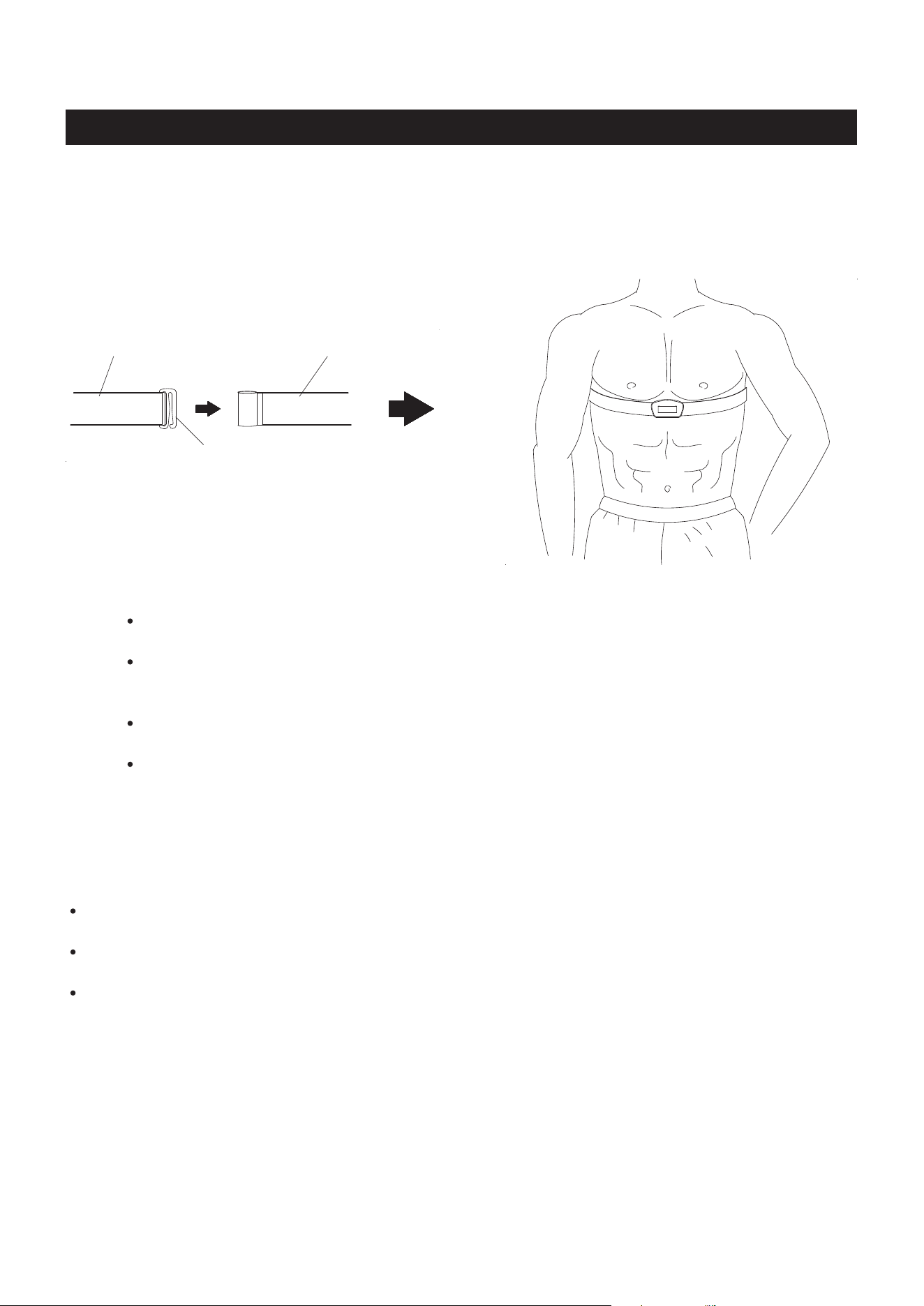
To wear the HEART RATE TRANSMITTER(116) around the chest, hook the hook end of the ELASTIC
SENSOR STRAP(117) to the other end of the ELASTIC SENSOR STRAP(117). Adjust the ELASTIC
SENSOR STRAP(117) to t your chest snugly as shown in the illustration below. Apply water or conductive
gel to moisten the heart rate sensor electrodes. These heart rate sensor electrodes must be wet and in
contact with your chest skin to properly detect your heart rate.
(117)Elastic Sensor Strap(117)Elastic Sensor Strap
Hook
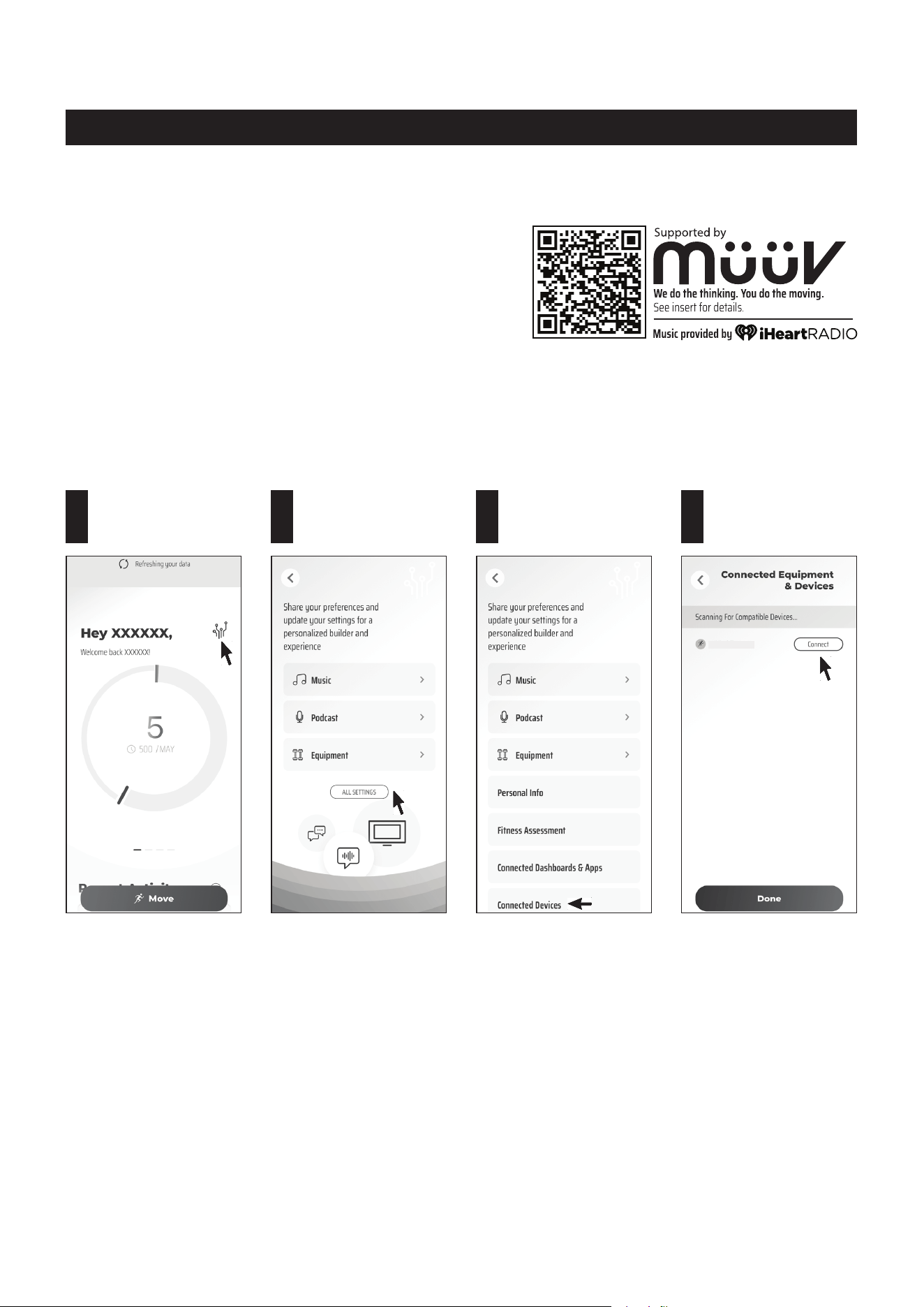
Tap on the Setting
icon.
1
Tap on
ALL SETTINGS.
2
Tap on Connected
Devices.
3
Tap on Connect next
to the "SERU-xxxxxx"
to connect.
4
OPERATIONAL INSTRUCTIONS
NOTE:
1. To fully operate your STAMINA│X AMRAP ROWER you
will need to download the free müüv app.
2. You will need to enable bluetooth in your phone settings
rst.
Power on the computer on your STAMINA│X AMRAP ROWER. Open the müüv app and follow the following
process to connect the rower to the müüv app. It will make your STAMINA│X AMRAP ROWER work with
the müüv application and many others. For more details and information, go visit https://müüv.t.
NOTE: Under low battery conditions, the COMPUTER(143) may still work, but may make the müüv app
unable to nd the bluetooth device to connect. Please pay attention to the issue and replace the
battery promptly.
SERU-XXXXXX
müüv
CONNECTION OPERATION
14
COMPUTER INSTRUCTIONS
15
In IDLE mode, press and release SELECT to cycle through each program option. Stop
on the program of your choosing. You can preset target values for DISTANCE, TIME, and
CALORIES, play the GAME, or select an Interval
Program
of 20/10, 10/20, or 10/10.
During exercise, press the button to switch between displaying DISTANCE and CALORIES.
Press to increase the preset values. Press the button and hold it down, the presetting value
will go faster, release the button to stop.
Press to decrease the preset values. Press the button and hold it down, the presetting value
will go faster, release the button to stop.
When selecting the programs, press the button to return to the previous program.
When you nish a running program, press the button to jump into the IDLE mode.
When selecting the programs and presetting target values, press the button to conrm.
Press the button and hold it down for three seconds to reset all functions to zero and restart
the computer.
During exercise, when back light is turned o, the rst pressing of this button will turn on
the back light. When the back light is still lit, press the button a second time to pause the
counting of all function values. Press the button a third time to restart the workout and
continue the counting of all function values.
Your STAMINA│X AMRAP ROWER utilizes an air fan system to create resistance for your workout. We
recommend that you use this computer console to vary your workout from session to session and note your
progress toward your tness goals. When used regularly in this way, the computer console can become an
important source of motivation and interest which will help keep you on track.
FUNCTION BUTTONS:
SELECT :
(UP) :
(DOWN) :
BACK :
ENTER/STOP
:
POWER ON:
POWER OFF:
Move the handlebar or press any button.
In IDLE mode, automatically shuts o after one minute of inactivity.
During workout, automatically shuts o after two minutes of inactivity.
SELECTBACK
STOP
ENTER

Displays ashing “500” for presetting the distance for preset DISTANCE Program, from
100 to 9999 meters, and counts down from the preset value.
Displays the distance you are traveling during exercise, from 1 meter up to 9999 meters.
For preset CALORIES Program, the matrix display will show a ashing “100” for presetting
the target calorie value, from 10 to 999 Kcals.
Displays the calories burned from zero up to 999 Kcals. The calories readout is an estimate
for an average user. It should be used only as a comparison between workouts on this unit.
NOTE: The display will switch to show DISTANCE and CALORIES every ve seconds.
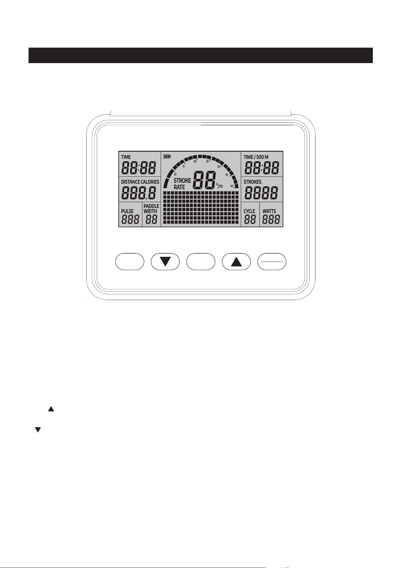
LCD DISPLAY INSTRUCTIONS
COMPUTER INSTRUCTIONS
16
TIME :
DISTANCE /
CALORIES:
Displays ashing "00:00" for presetting the time for preset TIME Program, from 1:00 to
99:00 minutes, and counts down from the preset value.
Displays the time during exercise, from 1 second up to 99:59 minutes.
STROKES: Displays the number of strokes you have taken, from zero to 9999 strokes.
PADDLE WIDTH:
Displays the traveling distance of eack stroke, from zero to 999 meters.
PULSE
:
Displays the heart rate, from 40 to 220 beats per minute during exercise.
To use this function, you must wear the HEART RATE TRANSMITTER(116) around your
chest so the receiver, which is built into the computer, registers your heart rate from the
HEART RATE TRANSMITTER(116) for display. If you do not wear the HEART RATE
TRANSMITTER(116) around your chest correctly the display window will be empty.
NOTE: The HEART RATE TRANSMITTER(116) is not a medical device. Maintaining
a consistent signal can be dicult due to the varying distances experienced during the
rowing stroke. The heart rate function is a great tool to optimize your workout, but should
be used as a reference only.
WATTS: Displays the amount of power being exerted from zero to 999 watts.
STROKE RATE:
Displays the current strokes per minute during exercise, from zero to 9999 strokes per
minute.
NOTE: The STROKE RATE INDICATOR will display the same number as the STROKE
RATE showed.
TIME / 500M: During exercise, displays the estimated time for traveling the distance 500 meters
according to your current rowing speed, from 1 second up to 99:59 minutes.
When an Interval Program is selected, 20/10, 10/20, and 10/10, displays a ashing “8” for
presetting the value of how many cycles you want to exercise, from
1 to 99,
the readout
of the CYCLE will
count down from the preset value when exercising.
CYCLE:
Matrix Display
Stroke Rate Indicator
For the preset function value programs, press the BACK button to enter IDLE mode. Or, press the
ENTER/
STOP
button and hold it down for three seconds to restart the computer. The computer will go through the
programs as follows and allow you to set the target value for the selected program. Use SELECT button to
select the program for DISTANCE, TIME, or CALORIES. You can only preset one function value for each
selected program. Use "
/ " buttons to input the value, and press
ENTER/STOP
button to conrm. After
the desired setting is chosen, begin pulling on the HANDLEBAR(3) to start the workout.
COMPUTER INSTRUCTIONS
17
Distance (100 to 9999 meters) Time (1:00 to 99:00) Calories (10 to 999 Kcals) Game
20/10 Interval Program 10/20 Interval Program 10/10 User Setting Interval Program
PROGRAM DESCRIPTIONS
This computer contains the programs, Normal Program, Distance, Time, Calories, Game, 20/10 Interval
Program, 10/20 Interval Program, and 10/10 User Setting Interval Program. Refer to the following for the
operation of these programs.
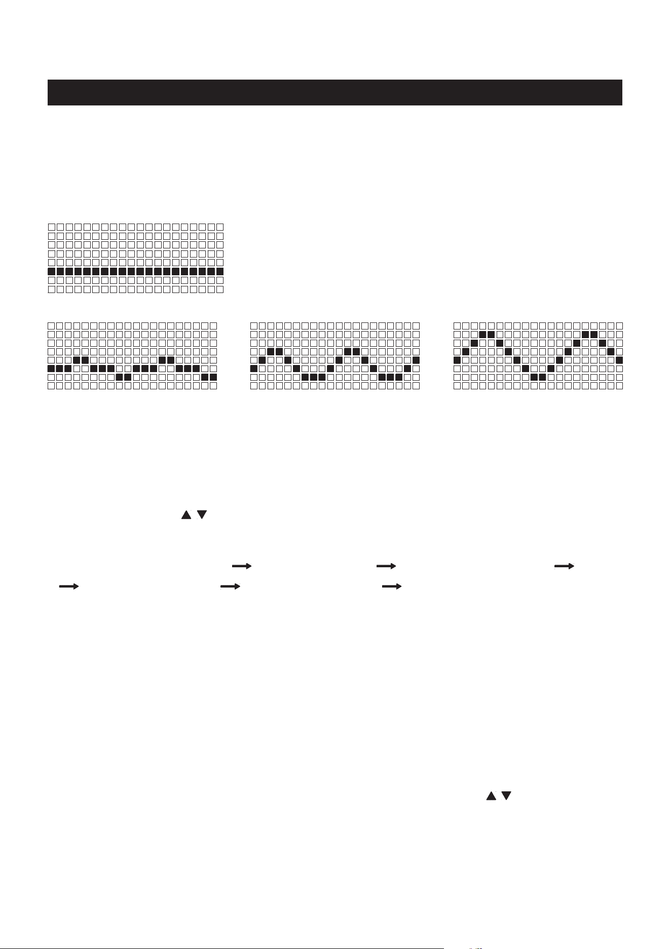
1. NORMAL PROGRAM:
You can pull on the HANDLEBAR(139) to power on the computer
and exercise with this program directly. All function values will count
up, and the matrix display will show the wave proles according to
your rowing speed. Refer to the following.
NOTE: This is the only program you can run with the built in generator
when the batteries are dead or not installed.
The medium waves display the
medium rowing speed.
The big waves display the high
rowing speed.
The small waves display the
low rowing speed.
2. DISTANCE PROGRAM: During exercise, the DISTANCE will count down from preset value, all other
functions will count up. The matrix display will show the estimated time for traveling the distance 500
meters according to your current rowing speed. When you complete the DISTANCE PROGRAM, the
computer will show "WINNER" and remind you with an audible alarm. Press the BACK button to jump
to the IDLE mode.
3. TIME PROGRAM: During exercise, the TIME will count down from preset value, all other functions will
count up. The matrix display will show the wave proles according to your rowing speed. Refer to the
above. When you complete the TIME PROGRAM, the computer will remind you with an audible alarm.
Press the BACK button to jump to the IDLE mode.
4. CALORIES PROGRAM: Use SELECT button to select this program. The matrix display will display
ashing "100" for presetting the target calorie value, from
10 to 999 Kcals
. Use " / " buttons to input the
value, and press
ENTER/STOP
button to conrm. Pull on the HANDLEBAR(139) to start the workout.
During exercise, the matrix display will count down from preset calorie value, all other function values
will count up, including the CALORIES readout at the left display window. When you complete the
CALORIES PROGRAM, the computer will show "END" and remind you with an audible alarm. Press
the BACK button to jump to the IDLE mode.
COMPUTER INSTRUCTIONS
18
NOTE: To exercise with the following programs, you will not be able to preset the function values. Refer
to the following for the operation of these programs.
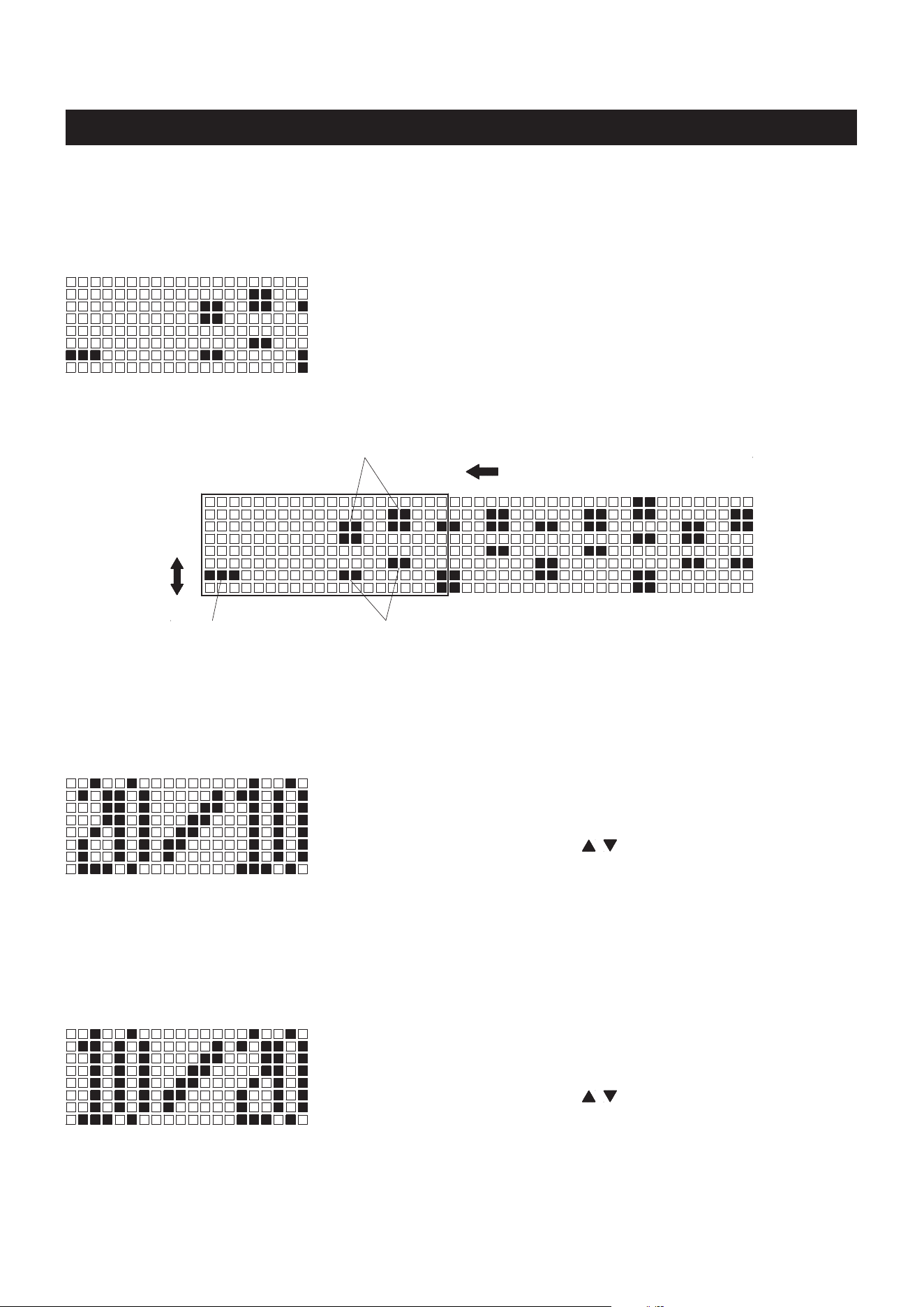
We call this program Score Game, use SELECT button to select
the program. The xed preset TIME for the game is 5 minuets, this
can’t be changed. Pull on the HANDLEBAR(139) to run the program
directly. When you complete the program, the matrix display will show
your point score and remind you with an audible alarm. Press the
BACK button to jump to the IDLE mode.
Hit the two square
block score two points.
Hit the four square block,
lose three points.
Matrix Display
The prole will move one interval per second.
YOUR POSITION
Depends on your rowing speed
and will move up and down, high
rowing speed will go high and
low rowing speed will go lower.
This program will allow the user to workout for 20 seconds, then rest
for 10 seconds, and will cycle this way.
Use SELECT button to select this program. The computer will display
ashing "8" for presetting the value of how many intervals you want
to exercise, from
1 to 99
. Use " / " buttons to input the value, and
press
ENTER/STOP
button to conrm. Pull on the HANDLEBAR(139)
to start to workout. The readout of the CYCLE will count down from
the preset value, all other function values will count up. When you
complete the program, the computer will remind you with an audible
alarm. Press the BACK button to jump to the IDLE mode.
5. GAME PROGRAM:
6. 20/10 INTERVAL PROGRAM:
This program will allow the user to workout for 10 seconds, then rest
for 20 seconds, and will cycle this way.
Use SELECT button to select this program. The computer will display
ashing "8" for presetting the value of how many intervals you want
to exercise, from
1 to 99
. Use " / " buttons to input the value, and
press
ENTER/STOP
button to conrm. Pull on the HANDLEBAR(139)
to start to workout. The readout of the CYCLE will count down from
the preset value, all other function values will count up. When you
complete the program, the computer will remind you with an audible
alarm. Press the BACK button to jump to the IDLE mode.
7. 10/20 INTERVAL PROGRAM:
19
COMPUTER INSTRUCTIONS
This program will allow the user to manually preset the workout
time and rest time from 10 to 99 seconds. The user will exercise for
the preset workout time, then rest for the preset rest time, and will
cycle this way. Use SELECT button to select this program. Use "
/ " and
ENTER/STOP
buttons to input the values of how many
intervals you want to exercise, workout time, and rest time. Pull on
the HANDLEBAR(139) to start to workout. The readout of the INTERVAL will count down from the preset
value, all other function values will count up. When you complete the program, the computer will remind
you with an audible alarm. Press the BACK button to jump to the IDLE mode.
8. 10/10 USER SETTING INTERVAL PROGRAM:
OPERATION DESCRIPTIONS
1. The back light of the LCD display will stay on for 10 seconds after the last pressing of any button, then
it will turn o. You can press any button to turn it on again.
2. To stop a running program, press the
ENTER/STOP
button. During exercise, when back light is turned
o, the rst pressing of this button will turn on the back light. When the back light is still lit, press the
button a second time to pause the counting of all function values. Press the button a third time to restart
the workout and continue the counting of all function values.
3. If you want to restart with a new program, press and hold the
ENTER/STOP
button down for three seconds
to reset all of the function values to zero and restart the computer. Use SELECT button to select a new
program.
C Batteries
HOW TO INSTALL AND REPLACE BATTERIES:
1. Open the Battery Door on the back of the COMPUTER(143).
2. The COMPUTER(143) operates with two C batteries (1.5V each),
the batteries are not included. Refer to the illustration to install or
replace the batteries.
1. Do not mix a new battery with an old battery.
2. Use the same type of battery. Do not mix an alkaline battery with
another type of battery.
3. Rechargeable batteries are not recommended.
4. Ultimate disposal of battery should be handled according to
all state and federal laws and regulations.
5. Do not dispose of batteries in re.
NOTE:
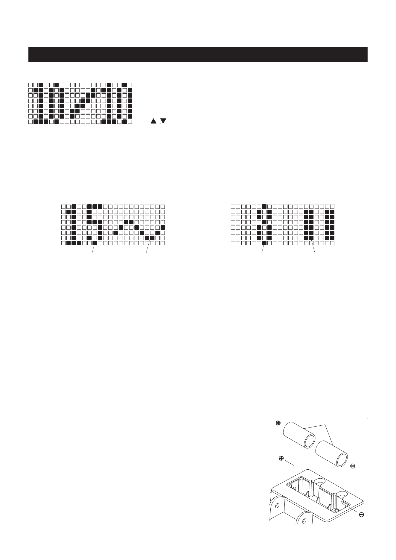
When working out with an Interval Program, 20/10, 10/20, and 10/10, the matrix display will show the
information as following.
When you complete running an Interval Program, if you continue rowing, the Interval Program will repeat
and continue to run.
Matrix display for the workout time
Workout time
counts down here.
Wave prole depends
on your rowing speed.
Matrix display for the rest time
Rest time counts
down here.
Pause symbol for
the rest time.
20
OPERATIONAL INSTRUCTIONS
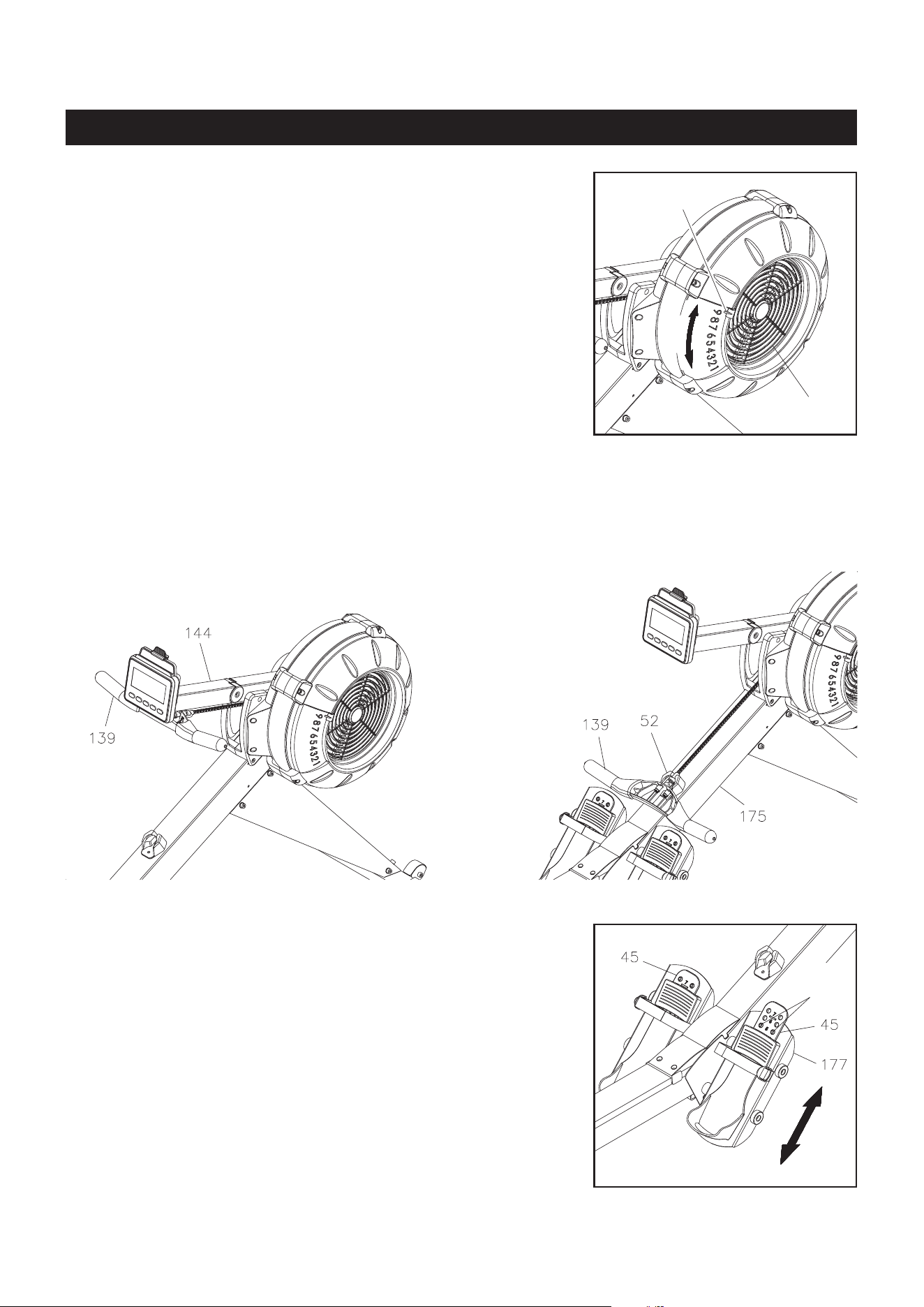
Damper(42)
Indicator
LOAD ADJUSTMENT
There is a DAMPER(42) built into the RIGHT FAN CAGE(43).
Move the Indicator in the DAMPER(42) to point to the numbers on
the RIGHT FAN CAGE(43) to adjust the load. There are settings
from 1 to 9. Setting #1 will provide the lowest resistance. Setting
#9 will provide the highest resistance.
HANDLEBAR POSITION
The HANDLEBAR(139) can be placed on the hook in the COMPUTER POST(144 ), refer to illustration A.
Or, you can place the HANDLEBAR(139) on the HANDLEBAR HOLDER(52) as shown in illustration B.
A.
B.
PEDAL CAP ADJUSTMENT
The position of the PEDAL CAPS(45) can be adjusted. Refer to
the illustration. Pull the PEDAL CAP(45) out from the two bulges
in the PEDAL SUPPORT(177), then lower or raise the PEDAL
CAPS(45) to the desired position. Lock the PEDAL CAPS(45) in
position by pressing the adjustment holes of the desired position
onto the two bulges.
Refer to the numbers on the PEDAL CAPS(45) to make sure that
PEDAL CAPS(45) are adjusted on the same position on both
sides.
Bulges
21
OPERATIONAL INSTRUCTIONS
COMPUTER POSITION ADJUSTMENT
To adjust, hold on both sides of the COMPUTER(143) and move the computer up or down by swinging
the COMPUTER POST(144) up or down. Rotate the COMPUTER(143) forward or backward to adjust its
angle.
USING THE PHONE CLAMP
Pull up the PHONE CLAMP(156), then slide the Cell Phone into the gap between the PHONE
CLAMP(156) and the COMPUTER(143). Move the PHONE CLAMP(156) downward to secure the Cell
Phone in position.
Cell Phone
SELECTBACK
STOP
ENTER
22
STORAGE
The MAIN FRAME(175) and the RAIL FRAME(176) can
be separated to minimize the unit size for storage. Remove
the PULL PIN(98) from the MAIN FRAME(175). Lift up the
MAIN FRAME(175) and pull out the RAIL FRAME(176) to
separate. Insert the PULL PIN(98) back into the hole in the
MAIN FRAME(175) for storage.
To store the STAMINA│X AMRAP ROWER, simply keep it in a clean dry place.
To avoid damage to the electronics, remove the batteries from the COMPUTER(143) before storing
the STAMINA│X AMRAP ROWER for one year or more.
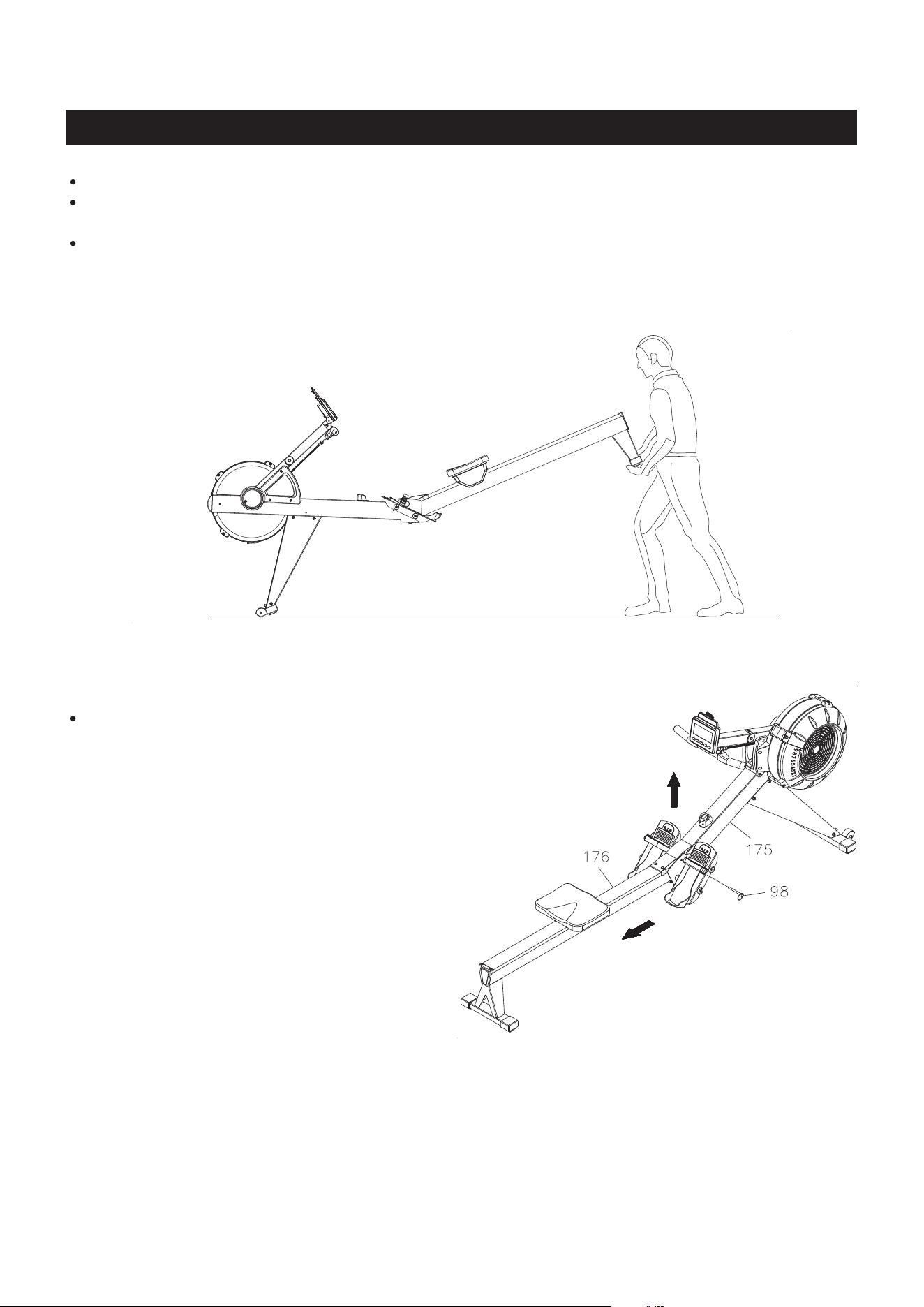
Move the STAMINA│X AMRAP ROWER with the MOVING WHEELS(66) on the FRONT STABILIZER
(4). Lift the Rear Stand of the RAIL FRAME(176) to move the STAMINA│X AMRAP ROWER. Refer
to the illustration below. Do not use the SEAT(51) to move the STAMINA│X AMRAP ROWER. The
SEAT(51) will move and the SEAT CARRIAGE(10) may pinch your hand or ngers.
The safety and integrity designed into the
STAMINA│X AMRAP ROWER
can only be maintained when
the
STAMINA│X AMRAP ROWER
is regularly examined for damage and wear. Special attention should
be given to the following:
MAINTENANCE
23
Pull on the HANDLEBAR(139) and verify that the Magnetic System provides tension and the seat
travel is smooth and stable.
Clean the roller tracks in the RAIL(14) with an absorbent cloth.
Verify that all nuts and bolts are present and properly tightened. Replace missing nuts and bolts.
Tighten loose nuts and bolts.
Check the condition of the CHAIN(36). Replace the CHAIN(36) if it is cracked or broken.
Verify that the CAUTION LABEL(115) is in place and easy to read. Call Stamina Products immediately
at 1-800-375-7520 for a replacement CAUTION LABEL(115) if it is missing or damaged.
It is the sole responsibility of the user/owner to ensure that regular maintenance is performed.
Worn or damaged components must be replaced immediately or the STAMINA│X AMRAP ROWER
removed from service until repair is made.
Only Stamina Products supplied components should be used to maintain/repair the STAMINA│X
AMRAP ROWER.
Keep your STAMINA│X AMRAP ROWER clean by wiping it o with an absorbent cloth after use.
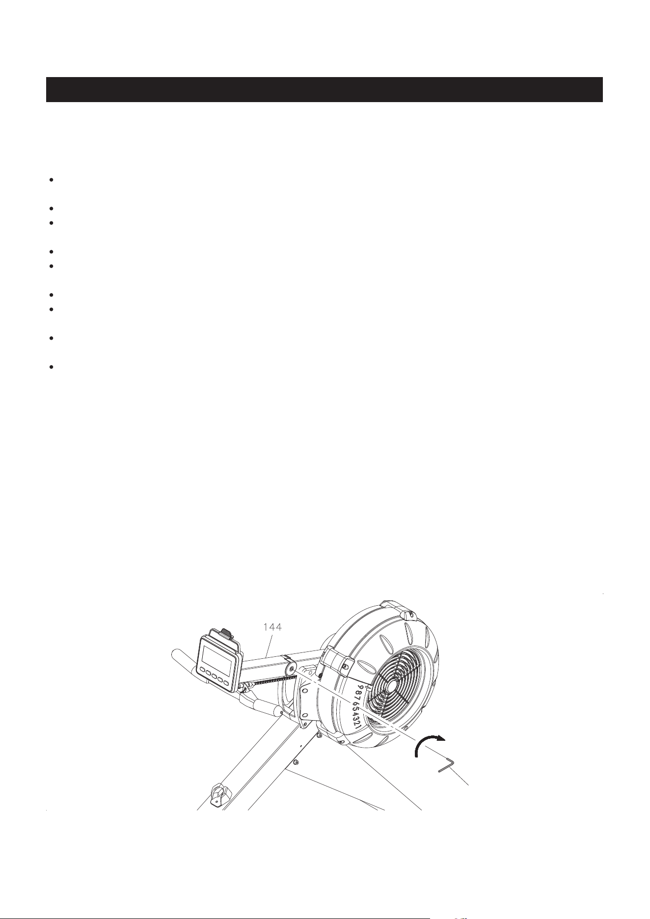
COMPUTER POST ADJUSTMENT
Over time the COMPUTER POST(144) may loosen. You can use the ALLEN WRENCH(5mm) to
tighten the SOCKET HEAD BOLT(M6x1x16mm)(99) which is located on the inside of the COMPUTER
POST(144). The COMPUTER POST(144) must be able to rotate, do not overtighten the bolt.
Allen Wrench (5mm)
MAINTENANCE
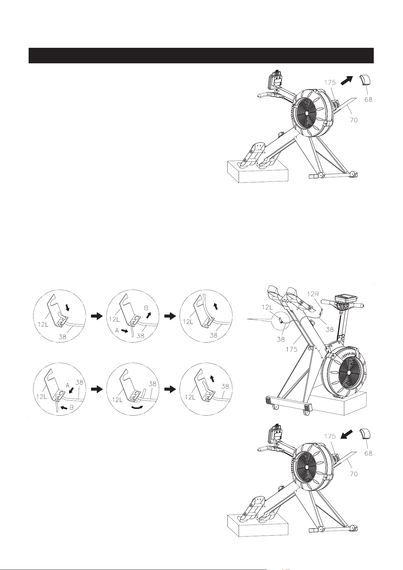
2. Position the MAIN FRAME ASSEMBLY(175) as shown in the below illustration. Unhook the LEFT
BUNGEE CORD HOOK(12L) from the MAIN FRAME(175). Make a mark on the BUNGEE CORD(38)
to move the hook forward 2 inches. Refer to View 1 to View 3 to untie the BUNGEE CORD(38) from
the LEFT BUNGEE CORD HOOK(12L), and move the hook forward 2 inches. Refer to View 4 to
View 6 to retie the BUNGEE CORD(38) to the LEFT BUNGEE CORD HOOK(12L). Hook the LEFT
BUNGEE CORD HOOK(12L) back into the MAIN FRAME(175) and push the hook to the left side to
touch the inner wall of the MAIN FRAME(175). CAUTION: Always use two hands with a secure
grip when re-attaching the BUNGEE CORD HOOKS(12L & 12R).
Unhook the RIGHT BUNGEE CORD HOOK(12R) from the MAIN FRAME(175). Do the same as
above to adjust the BUNGEE CORD(38) on the right side.
BUNGEE CORD ADJUSTMENT
Over time, about 250,000 strokes on HANDLEBAR(3),
your BUNGEE CORD(38) may stretch. Follow the
following process to adjust:
1. Position the MAIN FRAME ASSEMBLY(175) as
shown in the illustration. Remove the MAIN FRAME
CAP(68) from the MAIN FRAME(175). Slide out the
BOTTOM COVER(70) from the MAIN FRAME(175).
1. 2.
6.5.4.
3.
3. Position the MAIN FRAME ASSEMBLY(175)
as shown in the illustration. Slide the BOTTOM
COVER(70) back into the MAIN FRAME(175).
Press the MAIN FRAME CAP(68) into the MAIN
FRAME(175).
24
25
How you begin your exercise program depends on your physical condition. If you have been inactive for
several years or are severely overweight, start slowly and increase your workout time gradually. Increase
your workout intensity gradually by monitoring your heart rate while you exercise.
Initially you may only be able to exercise within your target zone for a few minutes; however, your aerobic
capacity will improve over the next six to eight weeks. It is important to pace yourself while you exercise
so you don't tire too quickly.
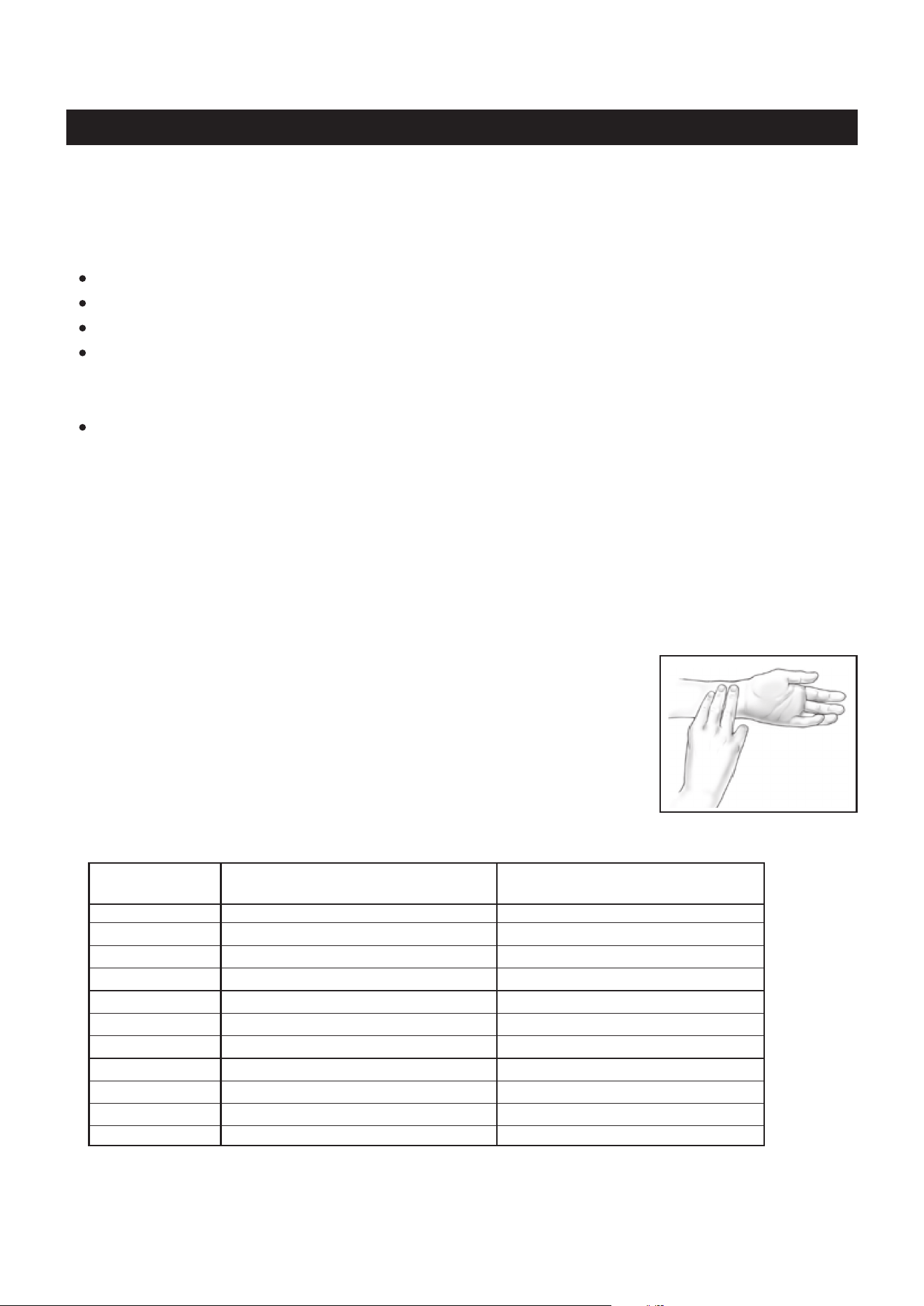
Measure your heart rate periodically during your workout by stopping the
exercise but continuing to move your legs or walk around. Place two or
three ngers on your wrist and take a six second heartbeat count. Multiply
the results by ten to nd your heart rate. For example, if your six second
heartbeat count is 14, your heart rate is 140 beats per minute. A six second
count is used because your heart rate will drop rapidly when you stop
exercising. Adjust the intensity of your exercise until your heart rate is at the
proper level.
wrist pulse
Remember to follow these essentials:
Have your doctor review your training and diet programs.
Begin your training program slowly with realistic goals that have been set by you and your physician.
Warm up before you exercise and cool down after you work out.
Take your pulse periodically during your workout and strive to stay within a range of 60% (lower
intensity) to 90% (higher intensity) of your maximum heart rate zone. Start at the lower intensity, and
build up to higher intensity as you become more aerobically t.
If you feel dizzy or lightheaded you should slow down or stop exercising.
To determine if you are working out at the correct intensity, use a heart rate monitor or use the table
below. For effective aerobic exercise, your heart rate should be maintained at a level between 60%
and 90% of your maximum heart rate. If just starting an exercise program, work out at the low end of
your target heart rate zone. As your aerobic capacity improves, gradually increase the intensity of your
workout by increasing your heart rate.
CONDITIONING GUIDELINES
Target Heart Rate Zone Estimated by Age*
* For cardiorespiratory training benefits, the American College of Sports Medicine recommends
working out within a heart rate range of 55% to 90% of maximum heart rate. To predict the
maximum heart rate, the following formula was used: 220 - Age = predicted maximum heart rate
20 years
25 years
30 years
35 years
40 years
45 years
50 years
55 years
60 years
65 years
70 years
Average Maximum
Heart Rate 100%
Age
110-180 beats per minute
107-175 beats per minute
105-171 beats per minute
102-166 beats per minute
99-162 beats per minute
97-157 beats per minute
94-153 beats per minute
91-148 beats per minute
88-144 beats per minute
85-139 beats per minute
83-135 beats per minute
200 beats per minute
195 beats per minute
190 beats per minute
185 beats per minute
180 beats per minute
175 beats per minute
170 beats per minute
165 beats per minute
160 beats per minute
155 beats per minute
150 beats per minute
Target Heart Rate Zone
(55%-90% of Maximum Heart Rate)

26
WARM-UP and COOL-DOWN
Warm-Up
The purpose of warming up is to prepare your body for exercise and to minimize injuries.
Warm up for two to ve minutes before strength training or aerobic exercising. Perform activities that
raise your heart rate and warm the working muscles. Activities may include brisk walking, jogging,
jumping jacks, jump rope, and running in place.
Cool-Down
The purpose of cooling down is to return the body to its normal, or near normal, resting
state at the end of each exercise session. A proper cool-down slowly lowers your heart rate and allows
blood to return to the heart. Your cool down should be completed after each strength training session.

LIMITED WARRANTY
MODEL 35-1423D
27
WARRANTY
Stamina Products, Inc. (“Stamina”) warrants to the original purchaser that this product will be free from
defects in materials and workmanship that arise under normal use, service, proper assembly and proper
operation in accordance with product warnings/instructions for a period of 90 days on the parts and three
years on the frame from the date of the original purchase from an authorized retailer. THIS WARRANTY
SHALL NOT APPLY TO ANY PRODUCT WHICH HAS BEEN SUBJECT TO COMMERCIAL USE,
ABUSE, MISUSE, ALTERATION OF ANY KIND OR TO ANY DEFECT OR CHANGE CAUSED BY
IMPROPER ASSEMBLY, REPAIR, REPLACEMENT, SUBSTITUTION OR USE WITH PARTS NOT
PROVIDED BY STAMINA. Commercial use includes use of product in athletic clubs, health clubs, spas,
gyms, and all other public or semipublic facilities whether or not the product’s use is in furtherance of a
prot making enterprise, and all other use which is not for personal purposes.
To implement this limited warranty, send a written notice stating your name, date, and place of purchase
and a brief description of the defect along with your receipt to Stamina Products, Inc. 2040 N Alliance
Ave, Springeld, Missouri, USA, MO 65803, or email us at customer[email protected], or call
us at 1-800-375-7520. If the defect is covered under this limited warranty, you will be requested to return
the product or part to us for free repair or replacement at our option.
NO ACTION FOR BREACH OF THIS LIMITED WARRANTY MAY BE COMMENCED MORE
THAN ONE (1) YEAR AFTER THE DATE THE ALLEGED BREACH WAS OR SHOULD HAVE
BEEN DISCOVERED. NO ACTION FOR BREACH OF ANY IMPLIED WARRANTY (INCLUDING
MERCHANTABILITY AND FITNESS FOR A PARTICULAR PURPOSE) MAY BE COMMENCED MORE
THAN ONE (1) YEAR AFTER DELIVERY OF THE PRODUCT TO THE PURCHASER. These warranties
are not transferable. IF ANY PART OF THE PRODUCT IS NOT IN COMPLIANCE WITH THIS LIMITED
WARRANTY OR ANY IMPLIED WARRANTY, THE REMEDY OF REPAIR OR REPLACEMENT IS THE
EXCLUSIVE REMEDY. If any claim is made under this limited warranty or any implied warranty, Stamina
reserves the right to require the product to be returned for inspection, at the purchaser’s expense, to
Stamina’s premises in Springfield, Missouri. Return of the enclosed warranty registration card is not
required for warranty coverage, but is merely a way of establishing the date and place of purchase.
Stamina SHALL NOT BE LIABLE FOR THE LOSS OF USE OF ANY PRODUCT, LOSS OF TIME,
INCONVENIENCE, COMMERCIAL LOSS OR ANY OTHER INDIRECT, CONSEQUENTIAL, SPECIAL
OR INCIDENTAL DAMAGES DUE TO BREACH OF THE ABOVE WARRANTY OR ANY IMPLIED
WARRANTY.
THIS LIMITED WARRANTY IS THE ONLY EXPRESS WARRANTY. NO ORAL OR WRITTEN
INFORMATION GIVEN BY STAMINA, ITS AGENTS OR EMPLOYEES, SHALL CREATE A WARRANTY
OR IN ANY WAY INCREASE THE SCOPE OF THIS WARRANTY. This warranty gives you specic legal
rights, and you may also have other legal rights which vary from state to state. ANY OTHER RIGHT
WHICH YOU MAY HAVE, INCLUDING ANY IMPLIED WARRANTY OF MERCHANTABILITY OR
FITNESS FOR A PARTICULAR PURPOSE, IS LIMITED IN DURATION TO THE DURATION OF THIS
WARRANTY.
The laws in some states aect the disclaimer or limitation of implied warranties and consequential and
incidental damages. If any such law is found applicable, the foregoing disclaimers and limitations of and
on implied warranties and consequential and incidental damages shall be deemed to be modied to the
extent necessary to comply with applicable law.
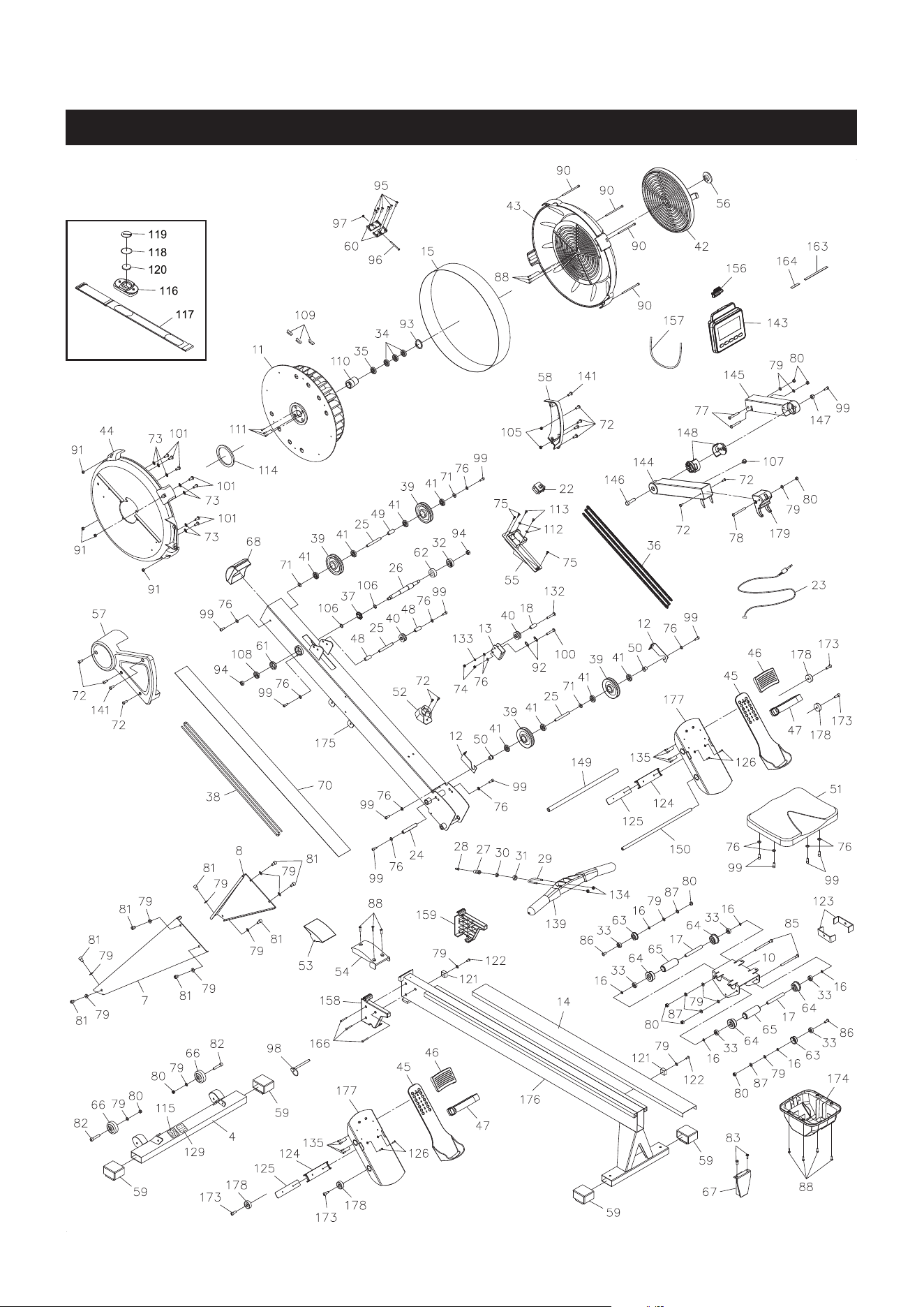
PRODUCT PARTS DRAWING
28
FRONT
BACK

PARTS LIST
29
4 Front Stabilizer 1
7 Left Support Leg 1
8 Right Support Leg 1
10 Seat Carriage 1
11 Fan 1
12 Bungee Cord Hook
2
13 Chain Idler Bracket 1
14 Rail 1
15 Outlet Perforation 1
16 Spacer (ø8.2 x ø12 x 3.2mm) 6
17 Long Spacer (ø8.2 x ø12 x 71.6mm) 2
18 Chain Roller Spacer (ø6.2 x ø10 x 15.5mm) 1
22 Generator 1
23 Sensor Wire 1
24 Shaft (M6 x 1, ø11.8 x 79.5mm) 1
25 Pulley Shaft (M6 x 1, ø10 x 76.5mm) 3
26 Fan Axle 1
27 Hook Connector 1
28 Chain Connector 1
29 U Bolt 1
30 Inner Spacer 1
31 Outer Collar 1
32 Bearing (6003RS) 1
33 Bearing (608ZZ)
6
34 Bearing (6201RS) 3
35 One-way Bearing (HF2016) 1
36 Chain, (1/4” pitch) 1
37 Sprocket 1
38 Bungee Cord 1
39 Bungee Cord Pulley 4
40 Chain Roller 2
41 Bearing (6000ZZ) 8
42 Damper 1
43 Right Fan Cage 1
44 Left Fan Cage 1
45 Pedal Cap 2
46 Toe Piece 2
47 Pedal Strap 2
48 Small Chain Roller Spacer (ø10 x ø16 x 30.5mm) 2
49 Pulley Spacer (ø10 x ø16 x 26.5mm) 1
50 Pulley Bushing 2
51 Seat 1
52 Handlebar Holder 1
53 Joint Cover 1
54 Fixed Joint Cover 1
55 Generator Base 1
56 Damper Securing Cap 1
57 Left Cover 1
58 Right Cover 1
PART# PART NAME QTY

PARTS LIST
30
PART# PART NAME QTY
59 Endcap (30mm x 60mm) 4
60 Connecting Plate 2
61 Bearing Cup (6001RS) 1
62 Bearing Cup (6003RS) 1
63 Guide Roller 2
64 Seat Roller 4
65 Roller Sleeve 2
66 Moving Wheel 2
67 Rail Cap
1
68
Main Frame Cap
1
70 Bottom Cover 1
71 Plastic Washer (ø10.2 x ø14 x 1mm thick) 3
72 Bolt, Round Head (M6 x 1 x 10mm) 11
73 Lock Washer, Internal Tooth (M6) 7
74 Nylock
Nut (M6 x 1)
2
75
Screw, Round Head
(ST4.2 x 10mm) 3
76 Washer (M6) 14
77
Bolt, Socket Head (M8 x 1.25 x 65mm)
2
78
Bolt, Button Head (M8 x 1.25 x 75mm) 1
79
Washer (M8)
19
80
Nylock
Nut (M8 x 1.25) 9
81 Bolt, Socket Head (M8 x 1.25 x 12mm)
8
82 Bolt, Socket Head (M8 x 1.25 x 40mm)
2
83 Bolt, Flat Head (M6 x 1 x 16mm)
2
85 Bolt, Socket Head (M8 x 1.25 x 110mm) 2
86 Bolt, Button Head (M8 x 1.25 x 25mm) 2
87 Lock Washer (M8) 4
88 Screw, Round Head
(ST4.2 x 16mm)
10
90
Bolt, Socket Head (M5 x 0.8 x 92mm) 4
91
Nut (M5 x 0.8)
4
92 Chain Hook
2
93 Inner C Ring (ø32) 1
94
Nylock
Nut (M10 x 1.5) 2
95 Screw, Round Head Self-Tapping (ST4.2 x 6mm) 6
96 Bolt, Socket Head (M4 x 0.7 x 45mm) 1
97 Nut (M4 x 0.7) 1
98 Pull Pin 1
99
Bolt, Socket Head (M6 x 1 x 16mm) 13
100 Bolt, Round Head (M6 x 1 x 30mm) 1
101 Bolt, Round Head (M6 x 1 x 10mm) 7
102 Screwdriver 1
103 Allen Wrench (6mm) 2
104 Wrench 1
105 Nut (M6 x 1) 2
106 PU Spacer 2
107 Grommet Plug 1
108 Bearing (6001RS) 1
109 Weight 3
110 Bearing Housing 1

31
PARTS LIST
PART# PART NAME QTY
111 Bolt, Socket Head (M4 x 0.7 x 12mm) 3
112 Washer
(ø3.5 x ø12 x 1mm thick) 2
113
Screw, Round Head
(ST3.5 x 12mm) 2
114 Magnet Ring 1
115 Caution Label 1
116 Heart Rate Transmitter 1
117 Elastic Sensor Strap 1
118 Battery Rubber Ring 1
119 Battery Cover 1
120 Button Battery (CR2032) 1
121 Seat Stopper 2
122 Bolt, Socket Head (M8 x 1.25 x 20mm) 2
123 Stopper Bracket 2
124 Strap Jacket 2
125 Jacket Plate 2
126 Screw, Flat Head
(M5 x 0.8 x 12mm) 4
129 Serial Decal 1
130 Manual 1
132 Bolt, Round Head (M6 x 1 X 30mm) 1
133 Lock Washer (M6) 1
134 Thick Nylock
Nut (M6 x 1)
2
135 Screw, Round Head Self-Tapping (ST4.2 X 10mm) 8
139 Handlebar 1
141 Bolt, Round Head (M6 X 1 x 12mm) 2
143 Computer 1
144 Computer Post 1
145 Extension Post 1
146 Shaft Bolt 1
147 Shat Spacer 1
148 Rotating Bushing 2
149 Large Pedal Shaft (ø16mm) 1
150 Pedal Shaft (ø12mm) 1
156 Phone Clamp 1
157 Rubber Band 1
158 Left Rail Gasket 1
159 Right Rail Gasket 1
163 EVA Pad 1
164 Short EVA Pad 1
166
Screw, Round Head
(ST4.2 x 35mm) 3
173 Bolt, Socket Head (M8 X 1.25 x 20mm) 4
174 Carriage Cover 1
175 Main Frame 1
176 Rail Frame 1
177 Pedal Support 2
178
Securing Cap 4
179
Mounting Cap 1

Model Number: ...................................................................................... Serial Number: .............................................................................................
Product Name: ..................................................................................................................................................................................................................................
Place Purchased: ..............................................................................................................................................................................................................................
Date of Purchase: .................................................................................. Purchase Price: ............................................................................................
First Name: ............................................................................................ Last Name: ...................................................................................................
City: .................................................................. State: ................................................................ Zip Code: .................................................
Email Address: ....................................................................................... Phone #: ( ) ......................................................................................
Would you like to receive email information or special oers from Stamina Products?* ____Yes ____No
*If yes, be sure your email address is included above.
Stamina Products, Inc.
2040 N Alliance Ave, Springeld, MO 65803
If there are missing or damaged parts, you can go to parts.staminaproducts.com and order those parts. If you have questions,
please contact customer care. Do not return the product. To order parts by mail, fill out the sheet below and fax it to
417-889-8064. The part will be mailed to your address.
Mr./Ms: ..............................................................................................................................................................................................................................................
Address: ........................................ ............................................................................................. Apt. #:..........................................................................
City: .................................................................. State: ................................................................ Zip Code: .................................................
IMPORTANT : We require your phone number to process the order!
Phone #: ( ) ................................................................................ Work Phone #: ( ) .............................................................................
Date of Purchase: ..................................................................................
Model #: ............................................................................................................................................................................................................................................
Purchased From: ..............................................................................................................................................................................................................................
IMPORTANT: Before lling out the portion below, make sure you have the correct information.
Refer to the parts list to make sure you're ordering the right parts!
Stamina Products, Inc.
2040 N Alliance Ave, Springeld, MO 65803
Detach and Mail or Fax the Form Above
TO CONTACT CUSTOMER CARE
For your convenience, Stamina’s customer care representatives can be reached by email at customer.care@staminaproducts.
com or by phone at 1-800-375-7520 (in the U.S.). Our customer care representatives are available Monday through Thursday
from 7:30 a.m. until 5:00 p.m., and Friday 8:00 a.m. until 3 p.m. Central Time.
TO REGISTER YOUR PRODUCT
Would you like to recieve email information or special oers from Stamina Products? Register at contact.staminaproducts.com
TELEPHONE
CUSTOMER CARE
Tel: 1 (800) 375-7520
FAX
CUSTOMER CARE
Fax: (417) 889-8064
MAIL
STAMINA PRODUCTS, INC.
ATTN: Customer Care
2040 N Alliance Ave, Springeld, MO 65803
ONLINE
CUSTOMER CARE
customer[email protected]
www.staminaproducts.com
To enact your warranty, please register your product by going to register.staminaproducts.com. Please have your product model
number (printed on the cover of this owner’s manual) and the serial number (printed on the black and white sticker on your
product) ready.
If you don’t have internet access, you can call customer care at 1-800-375-7520, or ll out and mail the product registration form
below to Stamina Products, Inc.; 2040 N Alliance Ave, Springeld, MO 65803.
PRODUCT REGISTRATION FORM
TO ORDER PARTS
Detach and Mail or Fax the Form Below
PARTS ORDER FORM
PART # DESCRIPTION QUANTITY
1 Rear Unit Assembly 1
EXAMPLE: