DIRECT DRIVE AIR COMPRESSORS
MODEL NO’s: SAC5002 SAC10002
Thank you for purchasing a Sealey product. Manufactured to a high standard, this product will, if used according to these
instructions, and properly maintained, give you years of trouble free performance.
IMPORTANT: PLEASE READ THESE INSTRUCTIONS CAREFULLY. NOTE THE SAFE OPERATIONAL REQUIREMENTS, WARNINGS & CAUTIONS. USE
THE PRODUCT CORRECTLY AND WITH CARE FOR THE PURPOSE FOR WHICH IT IS INTENDED. FAILURE TO DO SO MAY CAUSE DAMAGE AND/OR
PERSONAL INJURY AND WILL INVALIDATE THE WARRANTY. KEEP THESE INSTRUCTIONS SAFE FOR FUTURE USE.
1. SAFETY
1.1. ELECTRICAL SAFETY
WARNING! It is the responsibility of the owner and the operator to read, understand and comply with the following: You must check all
electrical products before use to ensure that they are safe. You must inspect power cables, plugs, sockets and any other connectors for
wear or damage. You must ensure that the risk of electric shock is minimised by the installation of appropriate safety devices. A Residual
Current Circuit Breaker (RCCB) should be incorporated in the main distribution board. We also recommend that a Residual Current Device
(RCD) is used. It is particularly important to use an RCD with portable products that are plugged into a supply which is not protected by an
RCCB. If in any doubt consult a qualified electrician. You must also read and understand the following instructions concerning electrical
safety:
1.1.1. The Health & Safety at Work Act 1974 makes owners of electrical appliances responsible for the safe condition of those appliances and
the safety of the appliance operators. If in any doubt about electrical safety, contact a qualified electrician.
1.1.2. Ensure that the insulation on all cables and on the appliance is safe before connecting it to the power supply.
1.1.3. Ensure that cables are always protected against short circuit and overload.
1.1.4. Regularly inspect power supply cables and plugs for wear or damage and check all connections to ensure that none are loose.
1.1.5. IMPORTANT: Ensure that the voltage marked on the appliance matches the power supply to be used and that the plug is fitted with the
correct fuse.
▲ DANGER! If the power cable for this equipment is damaged, it must be replaced by the manufacturer or it’s after-sales service or similarly
trained personnel to avoid danger.
8 DO NOT pull or carry the appliance by the power cable.
8 DO NOT pull the plug from the socket by the cable.
8 DO NOT use worn or damaged cables, plugs or connectors. Immediately have any faulty item repaired or replaced by a qualified
electrician.
1.1.6. OVER-CURRENT PROTECTION: The user has to make provision for the installation of the over-current protection of the power circuit in
accordance with EN 60204-1:2006.
NOTE: If using a transformer to supply the compressor, it must be rated at a minimum of 2kVA to allow the compressor to run efficiently.
1.2. GENERAL SAFETY
9 Before you connect the equipment to the mains supply make sure that the data on the rating plate are identical to the mains data.
9 Familiarise yourself with the application and limitations of the compressor.
9 Ensure the compressor is in good order and condition before use. If in any doubt DO NOT use the unit and contact your Sealey
Stockist.
9 Operation must be with all guards, covers, lids and enclosures correctly in place.
9 Fully assemble the compressor before using for the first time.
9 The concentration of processed gases that can displace breathing air shall be kept within acceptable levels. Reference EN 12021 for
acceptable levels of contaminants in breathing air.
9 Remove from mains supply when performing maintenance or inspections.
WARNING! Item must be serviced by an authorised agent. DO NOT tamper with or attempt to adjust pressure switch or safety valve.
8 DO NOT carry out any welding operations on any pressurised part of the vessel.
9 Before moving, or maintaining the compressor ensure it is unplugged from the mains supply and that the air tank pressure has been
vented.
9 Maintain the compressor in good condition and replace any damaged or worn parts. Use genuine parts only. Unauthorised parts may
be dangerous and will invalidate your warranty.
WARNING! All hoses and ttings shall be suitable for site use at the maximum allowable pressure of the portable compressor. Delivery
hoses should be fitted with a safety cord.
WARNING! In the event that an airline is cut or broken, the air supply must be turned off at the compressor. A broken airline which is
not supported is extremely dangerous and can whip around very quickly, both with the capability of striking people and blowing foreign
particles into the air.
WARNING! It is essential to use separators, water traps and draining facilities to process liquids produced by the compressor before
putting the unit into use.
9 The compressor may only be used in suitable rooms (with good ventilation and an ambient temperature from +5°C to +40°C). Ensure there
is no dust, acids, vapours, explosive gases, or flammable gases in the room. The air intake should be from a clean, outside air source.
9 Read the instructions relating to any accessory to be used with this compressor.
9 Ensure the safe working pressure of any air appliance used exceeds compressors output pressure. If using a spray gun, check that the
area selected for spraying is provided with an air change system/ventilation.
SAC5002 SAC10002 Issue 1 19/09/24
Original Language Version
© Jack Sealey Limited
Refer to
instructions
Wear eye
protection
Wear ear
protection
WARNING:
High Voltage
WARNING:
Hot surface
WARNING:
Automatic
start up
Indoor use only DO NOT open
the air cock
before an air
hose is attached
Work in progress
WARNING! Ensure the air supply valve is turned off before disconnecting the air supply hose.
9 To move a transportable compressor use the handle only.
Lift the compressor so that the front leg gives enough clearance for manoeuvring but maintain unit’s centre of gravity in front of the
wheels. DO NOT attempt to lift or move the compressor by any other means.
9 Use the compressor in a well ventilated area and ensure it is placed on a rm surface.
9 Keep tools and other items away from the compressor when it is in use, and keep area clean and clear of unnecessary items.
9 Ensure the air hose is not tangled, twisted or pinched.
9 Keep children and unauthorised persons away from the working area.
9 Only move the compressor by the handle (if portable).
8 DO NOT dis-assemble compressor for any reason. The unit must be checked by qualied personnel only.
8 DO NOT use the compressor outdoors, or in damp, or wet, locations.
8 DO NOT operate within the vicinity of ammable liquids, gases or solids.
8 DO NOT touch compressor cylinder head or pipe from the head to tank as these may be hot. DO NOT remove covers.
8 DO NOT use this product to perform a task for which it has not been designed.
8 DO NOT deface the certication plate attached to the compressor tank.
8 DO NOT cover the compressor or restrict air ow around the unit whilst operating.
▲ DANGER! DO NOT direct the output jet of air towards people or animals.
8 DO NOT operate the compressor without an air lter.
8 DO NOT allow anyone to operate the compressor unless they have received full instructions.
WARNING! The air tank is a pressure vessel and the following safety measures apply:
8 DO NOT tamper with the safety valve, DO NOT modify or alter the tank in any way and DO NOT strap anything to the tank.
8 DO NOT subject the tank to impact, vibration or to heat and DO NOT allow contact with abrasives or corrosives.
9 Drain condensation from tank daily and inspect inside walls for corrosion every three months and have a detailed tank inspection
carried out annually. The tank shell must not fall below the certied thickness at any point.
WARNING! If an electrical fuse blows, ensure it is replaced with an identical fuse type and rating.
9 When not in use, store the compressor carefully in a safe, dry, childproof location.
9 When the compressor is not in use, it should be switched off, disconnected from the mains supply and the air drained from the tank.
9 Under the PRESSURE SYSTEMS SAFETY REGULATIONS 2000 it is the responsibility of the owner of the compressor to
initiate a system of inspection that both denes the frequency of the inspection and appoints a person who has specic
responsibility for carrying out the inspection.
2. INTRODUCTION
V-Twin pumps with aluminium cylinders and cast iron liners for reduced weight and improved resistance to wear. Ideal for use where an
oil free air delivery is required. This is great for paint spraying as no oil can contaminate the supplied air. It also reduces maintenance
costs. Suitable for general-purpose workshop applications. Pump directly coupled to heavy-duty induction motor for reliable and quiet
operation. Precision welded receiver tank manufactured to meet Pressure Vessel Directive. Fitted with fully automatic pressure cut-out
switch, air regulator and pressure gauges for tank and supply. Supplied with handle and wheels. Fitted with 3-pin plug.
3. SPECIFICATION
4. ASSEMBLY
4.1. Remove compressor from packaging and inspect for any shortages
or damage. If anything is found to be missing or damaged, contact your
Sealey stockist.
4.1.1. Confirm that the mains voltage corresponds with the voltage shown on the
compressor data plate.
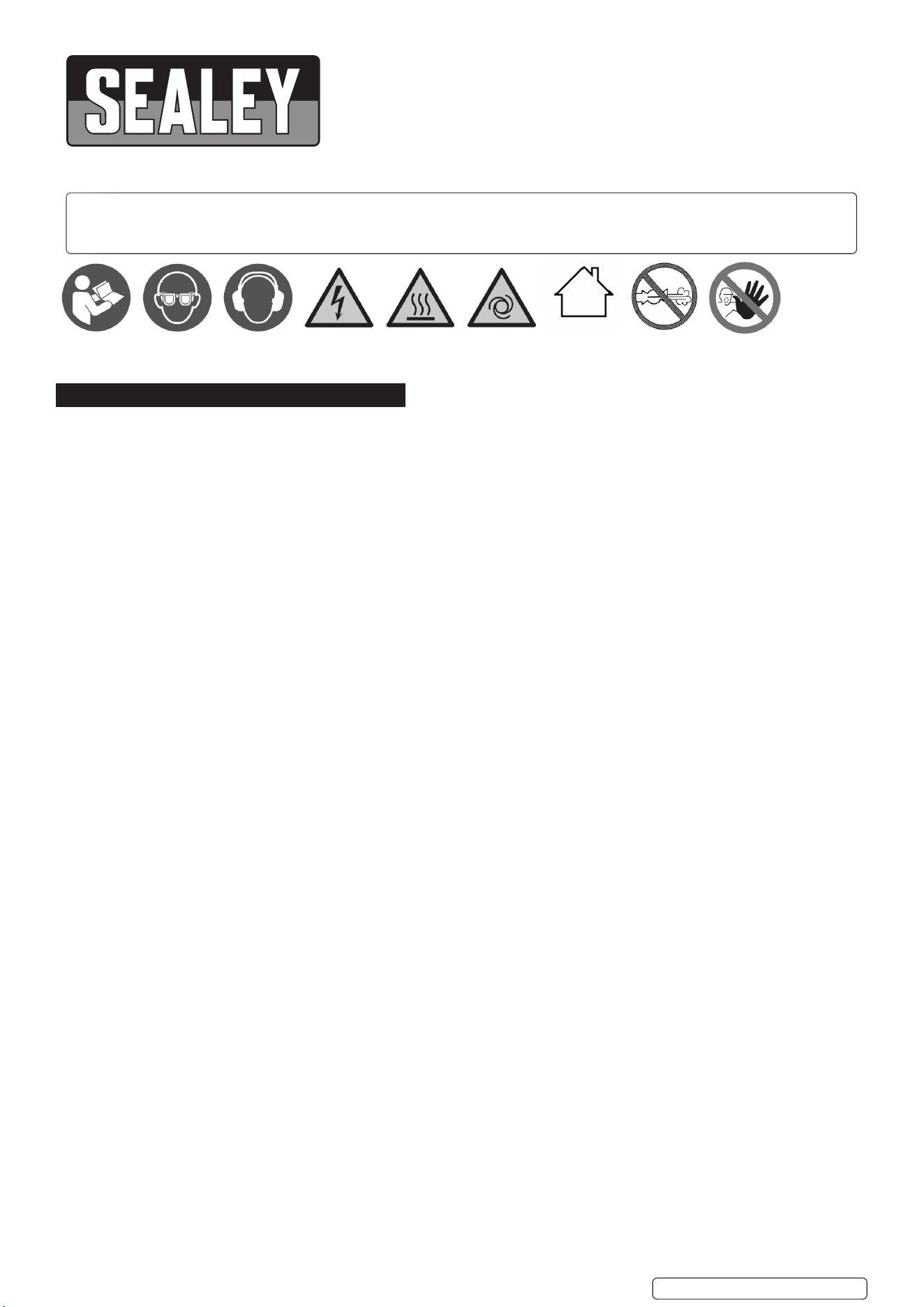
4.1.2. The compressor should be installed on a flat surface, or one that does not
exceed 10° either transversely or longitudinally, (see fig.2) as compressor
may tip over, and also allows good air circulation around the unit.
Additional Specication:
Short circuit current rating for each incoming power supply: 22A.
Full load current for each incoming supply: 9.0A@230V.
Intended media: Air.
Inlet discharge pressure and temperatures: Pressure
Temperature 70°C.
Maximum pressure ratio: 10bar ( or 1:10).
Pressure limits of the lubrication system: 2bar.
Temperature limits of the lubrication system: 100°C.
Maximum speed of the unit: 2900rpm.
Minimum speed of the unit: 2800rpm.
Tank Thickness: 2.5mm for 50L SAC5002 and 3.0mm for 100L
SAC10002.
Noise Test Code: EN ISO 2151:2008
Pressure and ow rate. (Pressure relief device.)
The safety valve will open at 8.8Bar (1.1 times of max working
pressure).
Flow rate 2960 L /M.
Original Language Version
© Jack Sealey Limited
SAC5002 SAC10002 Issue 1 19/09/24
Model No: SAC5002 SAC10002
Air Displacement cfm(L/min): 14.1cfm(400/min) 14.1cfm(400/min)
Applicable Standards:
EN IEC 61000-6-4:2019, EN IEC 61000-6-2:2019
EN 60204-1-2018, EN ISO 12100:2010
EN 1012-1:2010, EN 286-1:1998/A2:2005
Fuse Rating: 13A 13A
Maximum Free Air Delivery
cfm(L/min):
9.64cfm(272/min) 9.64cfm(272/min)
Maximum Pressure: 145psi(10bar) 145psi(10bar)
Minimum Rated Supply: 13A 13A
Motor Output: 3hp 3hp
Nett Weight: 39kg 53kg
Noise Level: 94dB(A) 94dB(A)
Outlet: Quick Release Coupling Quick Release Couplings
Phase: 1ph 1ph
Plug Type: 3-Pin BS 3-Pin BS
Power Supply Cable Length: 1.3m 1.3m
Product Life Applicable: No No
Receiver Capacity: 50L 100L
Size (W x D x H): 780 x 350 x 740mm 1050 x 450 x 800mm
Supply: 230V ~ 50Hz 230V ~ 50Hz
fig.
2
fig.
1
Tank drain valve
Original Language Version
© Jack Sealey Limited
4.2. Make sure the air intake is dry and dust free.
8 DO NOT set up the compressor in damp or wet areas.
4.2.1. The compressor may only be used in suitable areas (with good ventilation and an ambient temperature from 5°C to +40°C). There must
be no dust, acids, vapours, explosive gases or flammable gases in the room.
IMPORTANT: Take care when selecting tools for use with the compressor. Air tool manufacturers normally express the volume of air
required to operate a tool in cubic feet per minute (cfm). This refers to free air delivered by the compressor (‘air out’) which varies
according to the pressure setting. DO NOT confuse this with the compressor displacement which is the air taken in by the compressor (‘air
in’). ‘Air out’ is always less than ‘air in’ - due to losses within the compressor - and so it is important that, before choosing equipment, you
study the ‘Free Air Delivery’ figures shown in the Specification Chart.
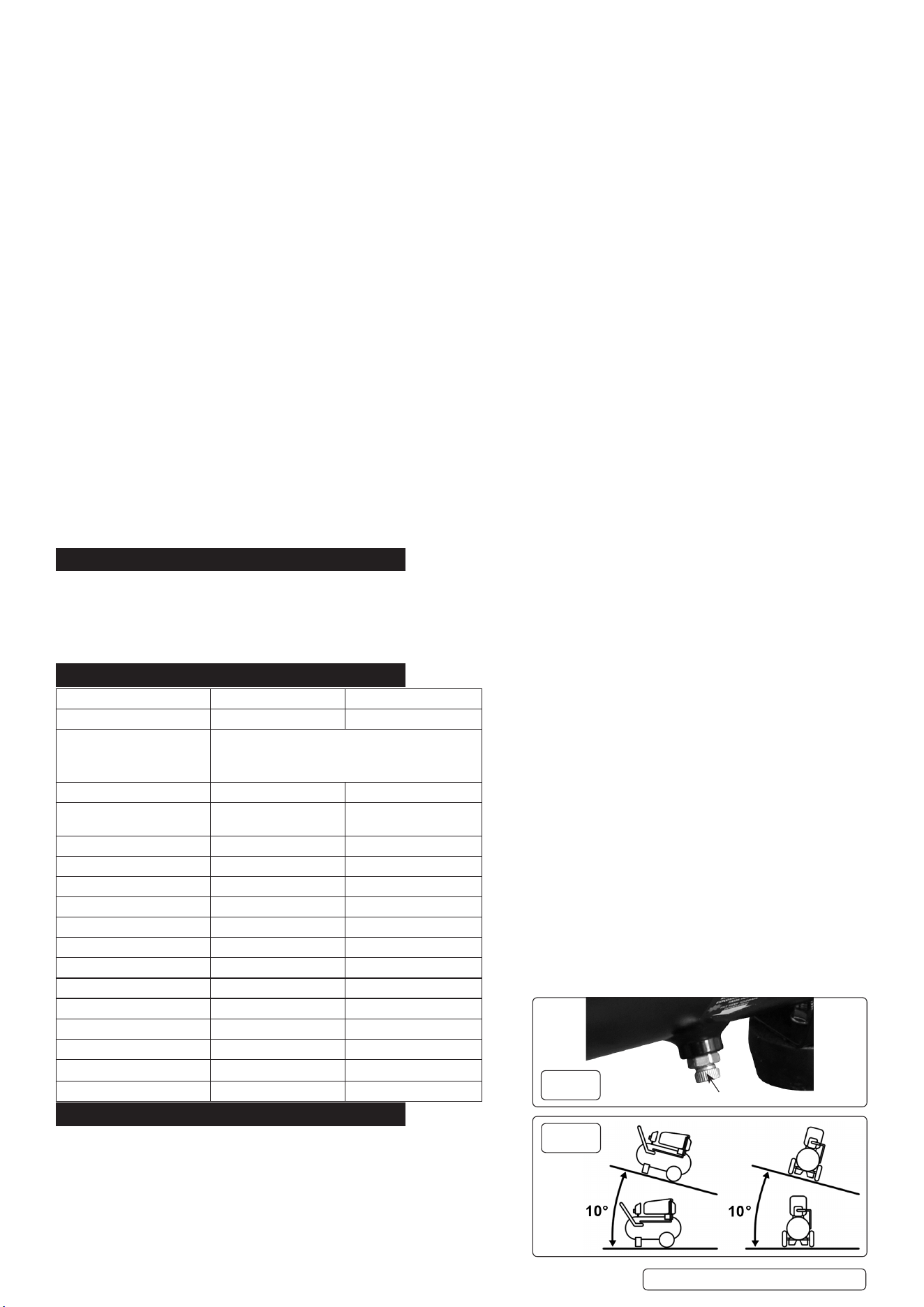
4.2.2. ATTACHING THE RUBBER FEET (model number SAC5002 only)
4.2.3. Remove the nut, spring washer and washer from one of the short bolts. Part no/SAC5001S-72
4.2.4. With the pressure tank on its side, insert the short bolt and washer through a supporting rubber foot and into the hole in the frame of the
tank. Fig.5
NOTE: The rubber feet should go on the front of the tank. The front end of the tank has 2 horizontal tubes on the top where the handle for
tank will be attached.
4.2.5. Place the washer then spring washer back onto the short bolt and secure it with the nut.
4.2.6. Repeat the same procedure on the other side of the tank with the second rubber foot.
4.3. ATTACHING FRONT WHEELS (model number SAC10002 only)
4.3.1. Repeat process as above using castor wheel set Part no/ SAC10001S-72. Fig.6
4.4. ATTACHING REAR WHEELS (both models)
4.4.1. Remove the nut, spring washer and washer from one of the short bolts. Part no/SAC5001S-71-SAC10001S-71
4.4.2. Place the wheel bolt through the wheel, then slide one of the washers back onto the bolt.
4.4.3. Place this through the hole in the wheel bracket below the tank.
4.4.4. Fasten the wheel bolt in position with a washer, spring washer and hex nut. Fig.7
4.4.5. Repeat the steps above to fit the second wheel on the opposite side of the tank.
4.5. ATTACHING THE HANDLE (model number SAC5002-71 and SAC10001S-77)
4.5.1. Loosen the four handle fixing bolts on the tank. Part no/ SAC5002-72 or SAC10001S-81
4.5.2. Slide the tank handle into the horizontal tubes, push the tank handle as far in as possible. Fig.8
4.5.3. Tighten the bolts to lock the tank handle in place.
5. OPERATION
5.1. STARTING UP THE COMPRESSOR
9 For the best practice, the compressor should be run without any load for 20
minutes before first use to lubricate the bearings and piston. This procedure should
be performed if the compressor has been stored for 6 months or more without
operation.
WARNING! ENSURE THAT YOU HAVE READ, UNDERSTOOD AND APPLIED
5.2. SECTION 1 SAFETY INSTRUCTIONS.
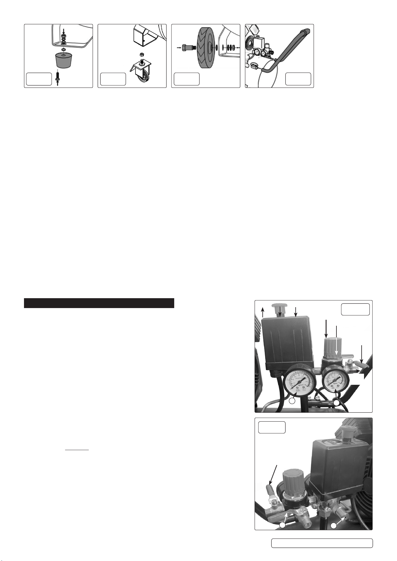
5.2.1. Make sure that the main switch (fig.9.1) is ‘OFF’ (down).
5.2.2. Ensure that the tank drain valve is closed (fig.1).
5.2.3. Connect the air tool required to the compressor via an air line connected to the air
outlet.
5.2.4. Plug the mains plug into the mains supply and start the compressor by pulling up
the main switch (fig.9.1).
5.2.5. Allow the pressure in the tank to rise to the maximum 8bar at which point the
compressor will automatically cut out. Tank pressure is shown on the larger gauge
(fig.9.6). The compressor automatically starts up again when the tank pressure
drops to 6bar.
5.2.6. Begin to gradually open the regulator by turning the knob (fig.9.2) until the small
gauge registers the required operating pressure specified for the tool to be used.
Always adjust up to the required pressure rather than down from a higher pressure.
The required setting, once achieved, can be locked by screwing the locking ring
(fig.9.3) up tight underneath the adjusting knob. Open air out tap (fig.9.4) for air to
flow.
5.2.7. You can now begin to use the tool. The compressor will operate automatically
cutting in and out as required to restore the air pressure in the tank. The pressure
switch (fig.10) stops the motor when the maximum tank pressure is reached and
restarts it when pressure falls below the minimum threshold.
5.2.8. If the motor does not cut in and out, but runs continuously when using an air
appliance, the capacity of the compressor may be too small for the appliance.
5.2.9. The main gauge (fig.9.6) indicates the pressure inside the main tank, NOT the
pressure supplied to the air equipment, which is shown on the smaller gauge
(fig.9.5).
SAC5002 SAC10002 Issue 1 19/09/24
fig.
5
fig.
6
fig.
7
fig.
8
1ON OFF
2
3
AIR
OUT
8
7
g.9
g.9b
5
6
AIR
OUT TAP
4
Should the pressure in the main tank exceed the pre-set maximum, the
safety valve (fig.9b.7) will activate. Clean the safety valve after working
1000 hours, along with the compressor thoroughly cleaned. See section
6.6. Cleaning.
WARNING! For this reason DO NOT tamper with, or adjust, the switch or
the safety valve.
5.2.10. When the compressor is not being used set the regulated pressure to zero
so as to avoid damaging the pressure regulator.
5.3. SHUTTING DOWN
To stop the compressor press down the main switch (fig.9.1).
When the compressor stops there will be a whistling sound as compressed
air is vented from the compressor head. DO NOT, other than in an
emergency, stop the compressor by switching off the mains power, or by
pulling the plug out, as the pressure relief will not then occur and motor
damage may result upon restart.
5.3.1. When you have finished using the compressor unplug the unit from the
mains power supply.
5.3.2. Set the outlet pressure on the regulator to zero.
5.3.3. Use a blow gun or similar to discharge any air in the tank. Rotate the pressure regulator anti-clockwise until it is fully closed; check the
regulated pressure gauge to ensure that it reads 0 psi.
5.3.4. Remove the air line and air tool.
5.3.5. The tank must now be drained. Release the air left in the tank by opening air tap (fig.9b.8). After, drain away condensation that may have
formed within the tank. Choose a suitable location for this operation and/or make provision to collect the condensation.
IMPORTANT: Wear ear and eye protection.
5.3.6. Open the tank drain valve (fig.1) slowly, allowing moisture to bleed from the tank. After bleeding, close the drain valve to prevent debris
building up in the valve.
WARNING! Water that is allowed to remain in the tank during storage will corrode and weaken the air tank, which could cause the tank to
rupture. To avoid serious injury, drain the tank on a daily basis.
5.4. SAFETY FEATURES
5.4.1. THERMAL CUT OUT: If the unit overheats the thermal cut out will operate and shut the unit down. Use ON/OFF switch and turn OFF.
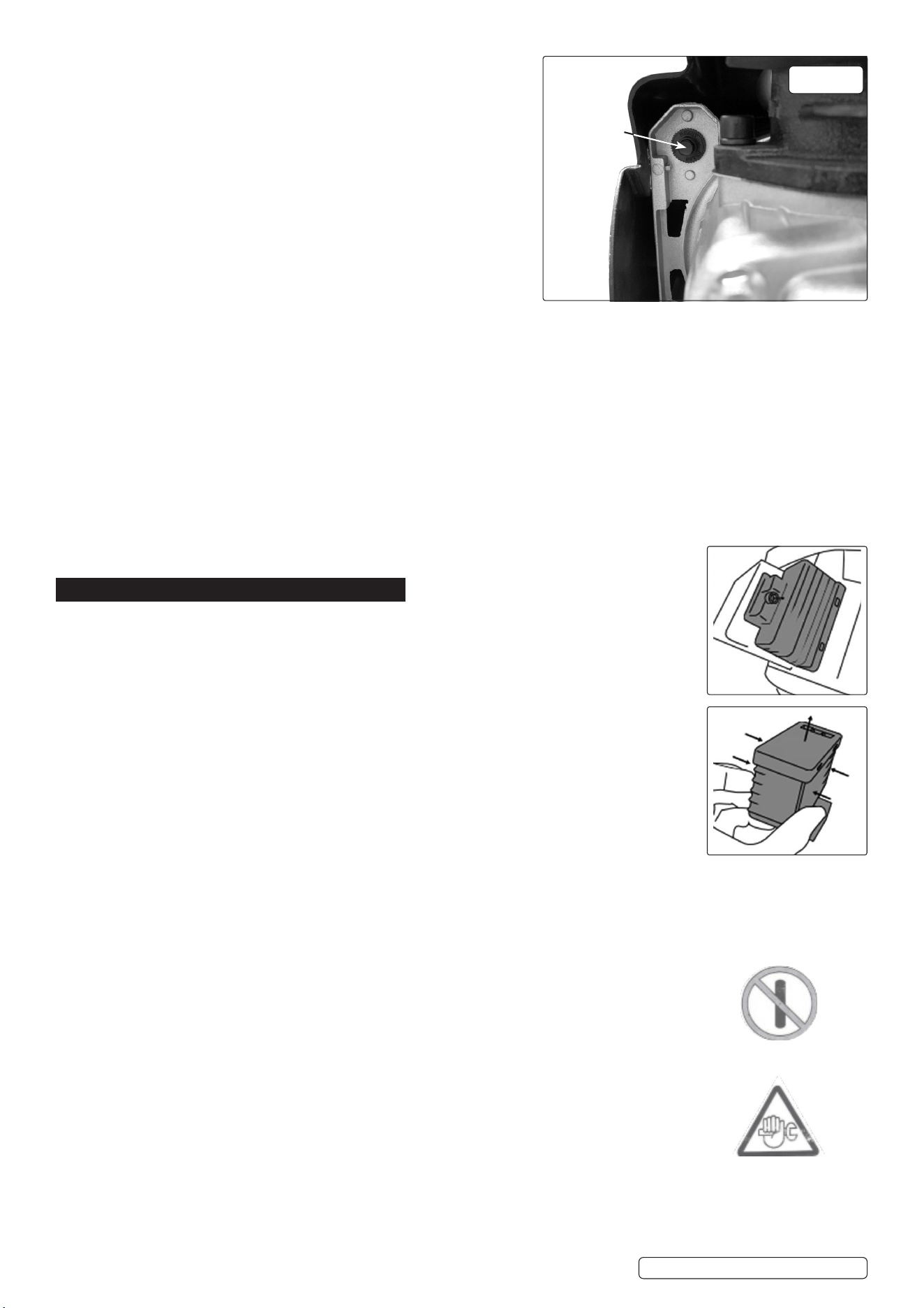
Allow the unit to cool down then press the reset button, located just inside the pump cover (fig.10). DO
NOT continue to use the unit if the overload switch trips again immediately after the reset.
6. MAINTENANCE & CLEANING
WARNING! Restrict availability of keys or tools to skilled or instructed persons only. Maintain by properly
trained personnel only.
WARNING! Before performing any maintenance operation, switch off the compressor, disconnect from
electricity supply and release all air from the tank. In order to keep the compressor in good working
condition, periodical maintenance is essential.
6.1. OPERATIONS TO BE CARRIED OUT DAILY:
WARNING! Display warning signs against reconnection whilst the compressor is being repaired such as:
8 DO NOT START MAINTENANCE WORK IN PROGRESS.
WARNING! Release all air pressure from the tank before opening the drain valve. Take care when
discharging air through the air outlets. The discharge air can cause dust, stones, or any other foreign
particles to be blown through the air at high pressure.
6.1.1. Drain condensation by placing a container under the valve fig.1, open the valve by turning anti-clockwise.
Re-tighten the valve after it has been drained.
6.1.2. Check that all nuts and bolts are tight, particularly those retaining the crankcase and cylinder head.
6.2. OPERATIONS TO BE CARRIED OUT EVERY 300 HOURS: (or more frequently, if the compressor operates in
a very dusty atmosphere).
6.3. CLEANING THE AIR FILTERS
6.3.1. The air filters prevent dust and dirt being drawn in. It is essential to clean these filters at least after every 300 hours in service. Clogged air
filters will decrease the performance of the compressor dramatically.
6.3.2. Allow the compressor to run and collect pressurised air in the tank. Once the motor has stopped running, turn the compressor off and
disconnect it from the power supply.
6.3.3. With an air hose and blow gun connected to the regulated pressure outlet, turn the pressure regulator until
the regulated pressure gauge shows a pressure of around 3bar.
6.3.4. Unscrew the bolt on the air filter housing with a hex key and remove the entire housing unit from the
compressor.
6.3.5. Gently squeeze the bottom part of the housing to disengage the plastic tabs and remove the lid.
6.3.6. Pull out the filter pads from the housing, tap it and spray with a blow gun to remove any dirt. Re-insert into
the housing.
6.3.7. Re-attach the lid and screw the air filter unit back onto the air compressor.
6.3.8. Repeat the above procedure for the other air filter unit.
6.4. SAFETY RELIEF VALVE
6.4.1. The safety relief valve has been set for the highest permitted pressure of the tank. It is prohibited to adjust
the safety relief valve or to remove it’s seal. The safety relief valve works automatically and requires no
maintenance by the user.
IMPORTANT! Failure to carry out maintenance tasks may invalidate the warranty on your compres-
sor.
WARNING - Air contaminants taken into the compressor will affect optimum performance. Example:
Body ller dust or paint overspray will clog the pump intake lter and may cause internal damage to
pump/motor components. NOTE: Any parts damaged by any type of contamination will not be covered by warranty.
Original Language Version
© Jack Sealey Limited
SAC5002 SAC10002 Issue 1 19/09/24
g.10
Reset Button
MAINTENANCE
WORK IN
PROGRESS
DO NOT START
6.5. INSPECTION OF PRESSURE TANK BOTH INSIDE AND OUT
6.5.1. Under the PRESSURE SYSTEMS SAFETY REGULATIONS 2000 it is the responsibility of the owner of the compressor to initiate a
system of inspection that both defines the frequency of the inspection and appoints a person who has specific responsibility for
carrying out the inspection.
6.6. CLEANING
6.6.1. Keep the safety devices free of dirt and dust as much as possible. Wipe the equipment with a clean or blow it with compressed air at
low pressure.
6.6.2. We recommend that you clean the appliance immediately after use.
6.6.3. Clean the appliance regularly with a damp cloth and some soft soap. DO NOT use cleaning agent or solvents; these may be
aggressive to the plastic parts in the appliance. Ensure that no water can get into the interior of the appliance.
6.6.4. You must disconnect the hose and any spraying tools from the compressor before cleaning. DO NOT clean the compressor with water,
solvents or the like.
6.7. STORAGE
6.7.1. Remove the mains plug from the socket and ventilate the appliance and all connected pneumatic tools.
Switch off the compressor and make sure that it is secured in such a way that it cannot be started up again by any unauthorised
person.
6.7.2. Store the compressor only in a dry location which is not accessible to unauthorised persons.
9 Take care when moving around work environment.
6.8. TRANSPORT
9 Remove air from tank before transporting the compressor.
6.9. SUPPLY CORDS
6.9.1. If the replacement of the supply cord is necessary, this has to be done by the manufacturer or a Sealey Service Agent in order to avoid
a safety hazard.
7. TROUBLESHOOTING
FAULT CAUSE REMEDY
Pressure drop in the tank. 1. Air leaks at connections.
2. Air leaks from cylinder head gasket.
1. Run compressor to maximum pressure, switch off. Brush soap solution over
connections and look for bubbles. Tighten connections showing leaks. If problem
persists, contact Authorised Service Agent.
2. Check tightness of head bolts, if leak continues contact Authorised Service Agent.
Pressure switch valve leaks when
compressor is idle.
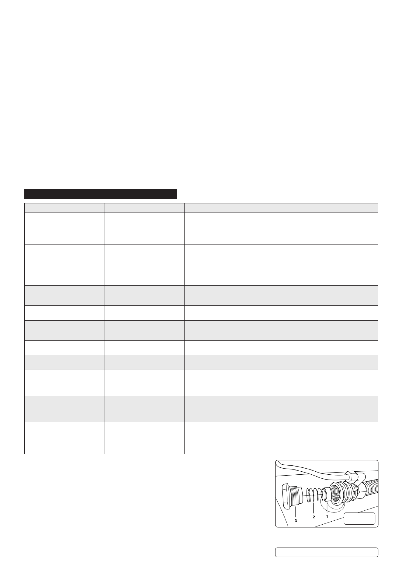
Non-return valve seal defective. Empty the air tank. Referring to (g.11), remove the non-return valve cap (g.11.3),
spring (g.11.2) and seal (g.11.1). Clean the seal and its seat, or if necessary replace
the seal and ret.
Air leaks from tank body or tank
welds.
Internal corrosion caused by infre-
quent tank draining or non permit-
ted modifications to tank.
Tank could rupture or explode. Cannot be repaired.
DISCONTINUE USE IMMEDIATELY.
Motor stops and will not restart. 1. Thermal cut out has operated.
2. Supply fuse has tripped.
1. Allow unit to cool for 30 minutes then press reset button (fig.10).
2. Reset fuse and restart unit. If repeated tripping occurs, replace the check valve
or contact Authorised Service Agent.
Compressor stops and will not
restart.
Motor failure. Contact Authorised Service Agent.
Compressor does not stop at
maximum pressure.
1. Pressure switch fault.
2. Filter clogged.
3. Head gasket or valve fault.
1. Contact Authorised Service Agent.
2. Replace filter element.
3. Contact Authorised Service Agent.
Compressor noisy with metallic
knock.
Bearing or piston damage. Contact Authorised Service Agent.
Excessive moisture in discharged
air.
High humidity environment. Drain tank after each use.
The compressor does not start. 1. No supply voltage.
2. Insufcient supply voltage.
3. Outside temperature is too low.
4. Motor is overloaded.
1. Check the supply voltage, the power plug and the socket-outlet.
2. Make sure that the extension cables are not too long.
3. Never operate with an outside temperature of below +5°C.
4. Allow the motor to cool down. If necessary, remedy the cause of the over heating.
The compressor starts but there is
no pressure.
1. The non-return valve leaks.
2. The seals are damaged.
3. The drain plug for condensation
water leaks.
1. Have an Authorised Service Agent replace the non return valve.
2. Check the seals and have any damaged seals replaced by Authorised Service Agent.
3. Tighten the screw by hand. Check the seal on the screw and replace if necessary.
The compressor starts, pressure
is shown on the pressure gauge,
but the tools do not start.
1. The hose connection has a leak.
2. The quick-lock coupling has a
leak.
3. Insufficient pressure set on the
pressure regulator.
1. Check the compressed air hose and replace if necessary.
2. Check the quick-lock coupling and replace if necessary.
3. Increase the set pressure with the pressure regulator.
Original Language Version
© Jack Sealey Limited
SAC5002 SAC10002 Issue 1 19/09/24
fig.
11
Original Language Version
© Jack Sealey Limited
SAC5002 SAC10002 Issue 1 19/09/24
Sealey Group, Kempson Way, Suffolk Business Park, Bury St Edmunds, Suffolk. IP32 7AR
01284 757500 sales@sealey.co.uk www.sealey.co.uk
WEEE REGULATIONS
Dispose of this product at the end of its working life in compliance with the EU Directive on Waste Electrical and Electronic
Equipment (WEEE). When the product is no longer required, it must be disposed of in an environmentally protective way. Contact
your local solid waste authority for recycling information.
NOTE: It is our policy to continually improve products and as such we reserve the right to alter data, specications and component parts
without prior notice. Please note that other versions of this product are available. If you require documentation for alternative versions, please
email or call our technical team on technical@sealey.co.uk or 01284 757505.
IMPORTANT: No Liability is accepted for incorrect use of this product.
WARRANTY: Guarantee is 12 months from purchase date, proof of which is required for any claim.
ENVIRONMENT PROTECTION
Recycle unwanted materials instead of disposing of them as waste. All tools, accessories and packaging should be
sorted, taken to a recycling centre and disposed of in a manner which is compatible with the environment. When
the product becomes completely unserviceable and requires disposal, drain any uids (if applicable) into approved
containers and dispose of the product and uids according to local regulations.
