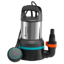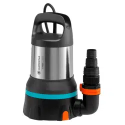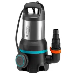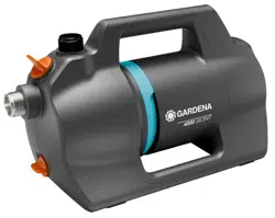
4100 Silent Art. 9050
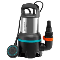
4200 Silent Art. 9054
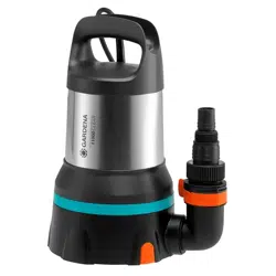
4300 Silent Art. 9056
Operator’s manual
Garden pumps
9050-52.960.02
Page 1 width 2 mm less: 208 mm
2
Fold-out Page width 5 mm less: 205 mm
Fold-out Page width 5 mm less: 205 mm
A1
A2
M
A
X
A3
Art. 9090
Art. 9091
BACKFLOW
A4
FULL
ON
ON
A5
3
Fold-out Page width 5 mm less: 205 mm
Fold-out Page width 5 mm less: 205 mm
A6
Art. 1723
Art. 1724
1
2
ß
G
A7
4
3
O1
min. 1,1 l
6
5
O2
min. 1,8 m
4
7
S1
4
5
8
6
T1
9
4
Garden pumps
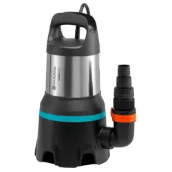
4100 Silent / 4200 Silent / 4300 Silent
Translation of the original instructions.
1. SAFETY WARNINGS
1.1. Explanation of the symbols
Read operator’s manual.
1.2. General safety warnings
1.2.1. General pump safety warnings
WARNING!
Electric shock!
Risk of injury due to electric current.
´ The product must be supplied through a residual current
device (RCD) having a rated residual operating current not
exceeding 30 mA.
´ Disconnect the product from the mains before you put it into
storage, maintain it or replace parts. Thereby the disconnected
socket must be in
the visual range.
1.2.2. Garden pump safety warnings
1.2.2.1 Safe operating practices:
The water temperature should not exceed 35 °C.
The pump must not be used when people are in the water.
Pollution of the liquid could occur due to leakage of lubricants.
1.2.2.2 Circuit breakers:
Thermal protection switch:
In the event of an overload, the pump is switched o by the built-in thermal motor
protection. After sucient cooling of the motor, the pump is operational again.
1.3. Additional safety warnings
1.3.1. Intended use
This product may be used under supervision, or if instruction regarding the safe
use of the product has been provided and the resulting dangers have been
understood, by children aged 8 and above, as well as by persons with physical,
sensory or mental disabilities or a lack of experience and knowledge. Children
must not be allowed to play with the product. Cleaning and user maintenance
shall not be carried out by children unless they aged 8 years and above and
supervision.
The use of this product by young people under the age of 16 is not recom-
mended.
The GARDENA Garden pump is intended to pump ground water and rain
water, tap water and water containing chlorine in private domestic gardens and
allotments.
The product is not intended for long term use (professional use).
The product is not intended for continuous running.
1.3.1.1 Liquids to be pumped:
The GARDENA Garden Pump must only be used to pump water.
DANGER!
Risk of injury!
The pump must not be used for the delivery of salt water, muddy water, corro-
sive, easily inflammable or explosive liquids (e. g. petrol, paraffin, thinners), oil,
heating oil or foodstuffs.
1.3.1.2 Pressure amplification:
The inlet pressure must be protected by an adjustable pressure relief valve. When
the pump is used for pressure amplication, the maximum permissible internal
pressure must not exceed 6 bar. The maximum inlet pressure is therefore:
GARDENA Garden pump 4100 Art. 9050 Max. 2.4 bar
GARDENA Garden pump 4200 Art. 9054 Max. 2.1 bar
GARDENA Garden pump 4300 Art. 9056 Max. 1.7 bar
1.3.2. Additional electrical safety warnings
DANGER!
Risk of cardiac arrest!
This product generates an electromagnetic field while it operates. This electro-
magnetic field may affect the functionality of active or passive medical implants
(e. g. pacemakers), which may result in serious injury or death.
g Consult your doctor and the manufacturer of your implant before using this
product.
g After using the product, disconnect the mains plug from the mains socket.
The pump must be installed in a stable and ood-proof location and protected
against falling into the water. Take care that the pump cannot fall into water.
Position the pump at a safe distance (min. 2 m) from the liquid to be pumped.
As an additional safety device an authorised safety switch can be used.
Ask your electrician for his advice.
If the supply cord is damaged, it must be replaced by the manufacturer, its
service agent or similarly qualied persons in order to avoid a hazard.
Protect the mains plug and the mains power cable from heat, oil and sharp
edges.
Do not use the power cable for carrying the pump or for unplugging.
Place the pump in a ood-proof location.
Please regularly check the connecting line.
Before using, always subject the pump (especially the power cables and
the power connections) to a visual inspection.
A pump which is damaged must not be used.
In the event of damage, have the pump checked by GARDENA Service.
Electrical changes are only conducted by an electrical specialist.
Before lling, dismantling, maintenance disconnect the mains.
When using our pumps with a generator, the warnings of the generator
manufacturer must be observed.
1.3.2.1 Cables:
If extension cables are used, these must comply with the minimum cross-sections
in the table below:
Voltage Cable length Cross section
230 – 240 V / 50 Hz Up to 20 m 1.5 mm²
230 – 240 V / 50 Hz 20 – 50 m 2.5 mm²
1.3.3. Additional personal safety warnings
DANGER!
Risk of suffocation!
Small parts can be easily swallowed.
g Keep toddlers away when you assemble the product.
DANGER!
Risk of injury from hot water!
Pumped water is under pressure and when it hits the body or eyes
directly can cause injury.
If the pump is operated for prolonged periods of time (> 5 min.) with the
delivery side closed, the water in the pump may heat up so that there is
arisk of scalding yourself with hot water.
g Let the pump operate for max. 5 minutes against the closed pressure
side or with missing water supply.
If the water supply on the intake side of the pump fails, the water in the
pump can heat up so that if water emerges, injuries could be caused by
the hot water.
g Disconnect the pump from the mains and let the water cool.
g Do not open any caps and screw connections when the water is hot.
g Before restarting, secure the water supply on the suction side and fill
the pump completely with water.
If hoses or pipes are exposed to the sun, they can become very hot.
Do not use the product with loose hair.
When connecting the pump to the water supply system, the country-specic san-
itary regulations must be observed to prevent water not of drinking water quality
being drawn back in.
Consult a specialist for sanitary installations.
In order to avoid dry-running of the pump, take care that the end of the suction
hose is always submerged into the liquid.
Before each operation, ll the pump with water up to the overow (min. 1.1 l)!
When lling the pump with water, make sure that no hoses or consumers are
connected to the pump and that the pump is generally in a horizontal position.
1. SAFETY WARNINGS .....................................4
2. ASSEMBLY ............................................5
3. OPERATION ............................................5
4. MAINTENANCE .........................................6
5. STORAGE .............................................6
6. TROUBLESHOOTING ....................................6
7. TECHNICAL DATA .......................................7
8. ACCESSORIES / SPARE PARTS .............................7
9. DISPOSAL .............................................7
10. PERFORMANCE CHARACTERISTICS ........................8
11. WARRANTY / SERVICE ...................................9
12. EU-DECLARATION OF CONFORMITY ........................9
5
Make sure that the hoses are laid without kinks.
Sand and other abrasive substances cause increased wear and reduce the
pump’s output.
Use a pump pre-lter for pumping sandy liquids.
Pumping dirty water, e. g. stones, pine needles etc., can cause damage to the
pump.
Do not pump dirty water.
The minimum ow rate is 90 l/h (1.5 l/min). Connection devices with a lower ow
rate must not be operated.
2. ASSEMBLY
DANGER!
Risk of injury!
Risk of injury due to accidental starting.
g Unplug the plug of the mains cable from the mains socket.
2.1. Installation site
• When installing below the water level, a shut-off device must be
installed to prevent unwanted water loss.
• The installation site must be horizontal, solid and dry and allow the
pump to stand securely.
• It must be at a distance of at least 2 m from the water.
• The pump must be installed in a flood-proof location with sufficient ven-
tilation in the area of the ventilation slots.
• The distance to the walls must be at least 5 cm.
• Dirt (e. g. sand or soil) must not be sucked in through the ventilation
slots.
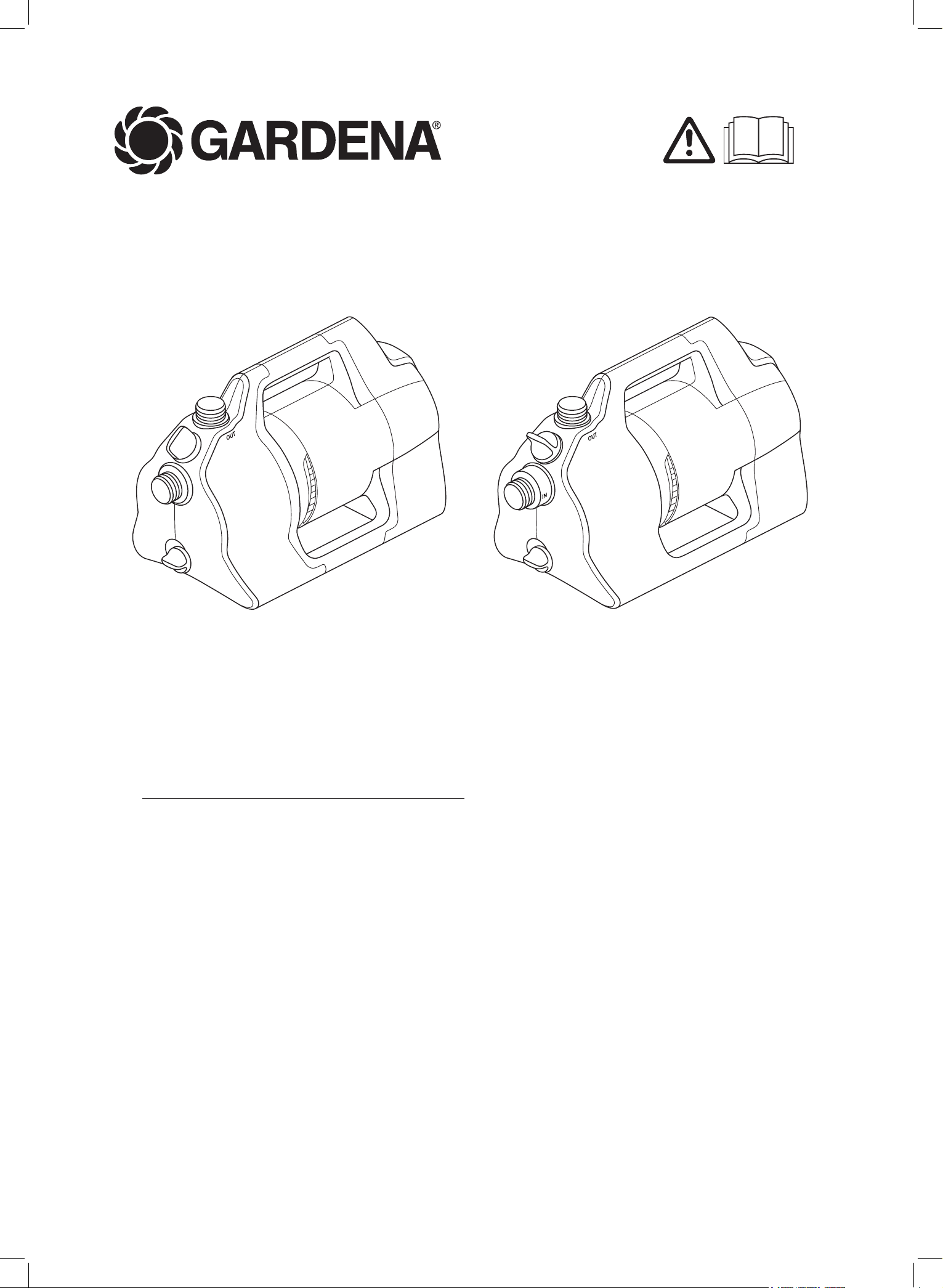
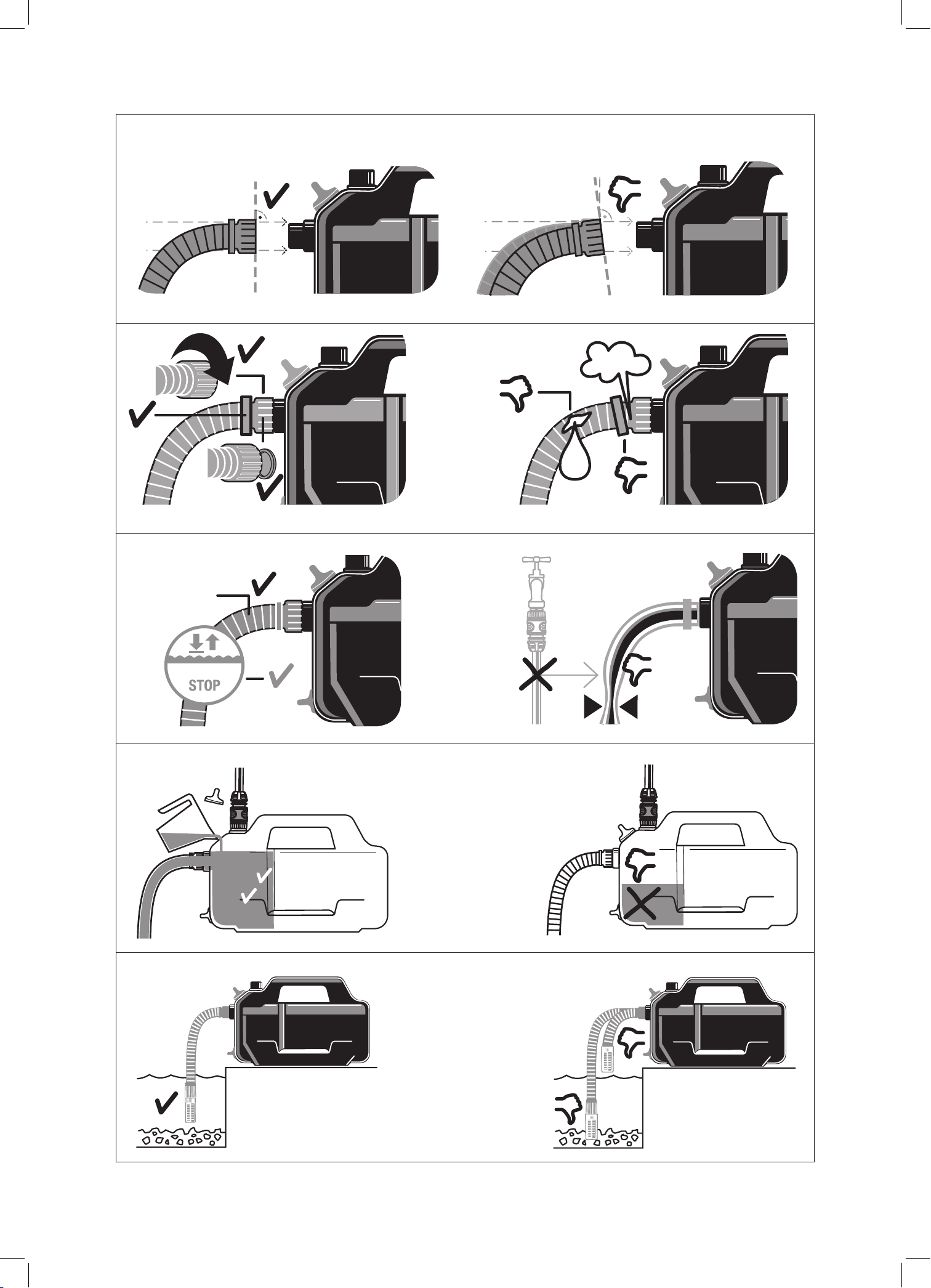
2.2. To connect the hose to the suction side [ Fig. A6 ]
The connector on the suction side
1
is equipped with a 33.3 mm (G 1")
external thread.
The connection piece on the suction side may only be tightened
byhand [ Fig. A2 ].
In order to reduce the suction time, it is advisable to use a suction hose
with backflow preventer avoiding automatic draining of the suction hose
when the pump has been switched off [ Fig. A3 ].
Sucking in air in the suction system can lead to functional failure and
increased noise generation.
g Connect the suction system carefully.
g Check the gasket regularly and replace it if necessary.
Don’t use any hose quick connection system fittings on the suction side.
A vacuum-resistant suction hose must be used on the suction
side:
• e. g. the GARDENA Suction Unit Art. 9090 / 9091 / 9092
• or the GARDENA Bore Hole Suction Hose Art. 1729.
• Connect suction hoses
2
without threaded connection via a suction
hose connection piece (e. g. Art. 1723 / 1724) to the connection of the
suction side and screw it airtight.
2.2.1 There are 2 types of connection systems
Intended for at gasket
No thread sealing tape is required.
g Make sure that the flat gasket
G
is inserted in the suction hose
connection piece and is undamaged.
Intended for thread sealing tape
No flat gasket is required.
An unsuitable sealing system can lead to leaks.
g Use the sealing system intended for this purpose.
1. Make sure that the flat gasket
G
is inserted in the suction hose
connection piece.
2. Screw the vacuum-resistant suction hose
2
airtight on the connector
on the suction side
1
. The connection piece must be placed straight
on [ Fig. A1 ].
3. Lay the suction hose
2
straight and free of twists.
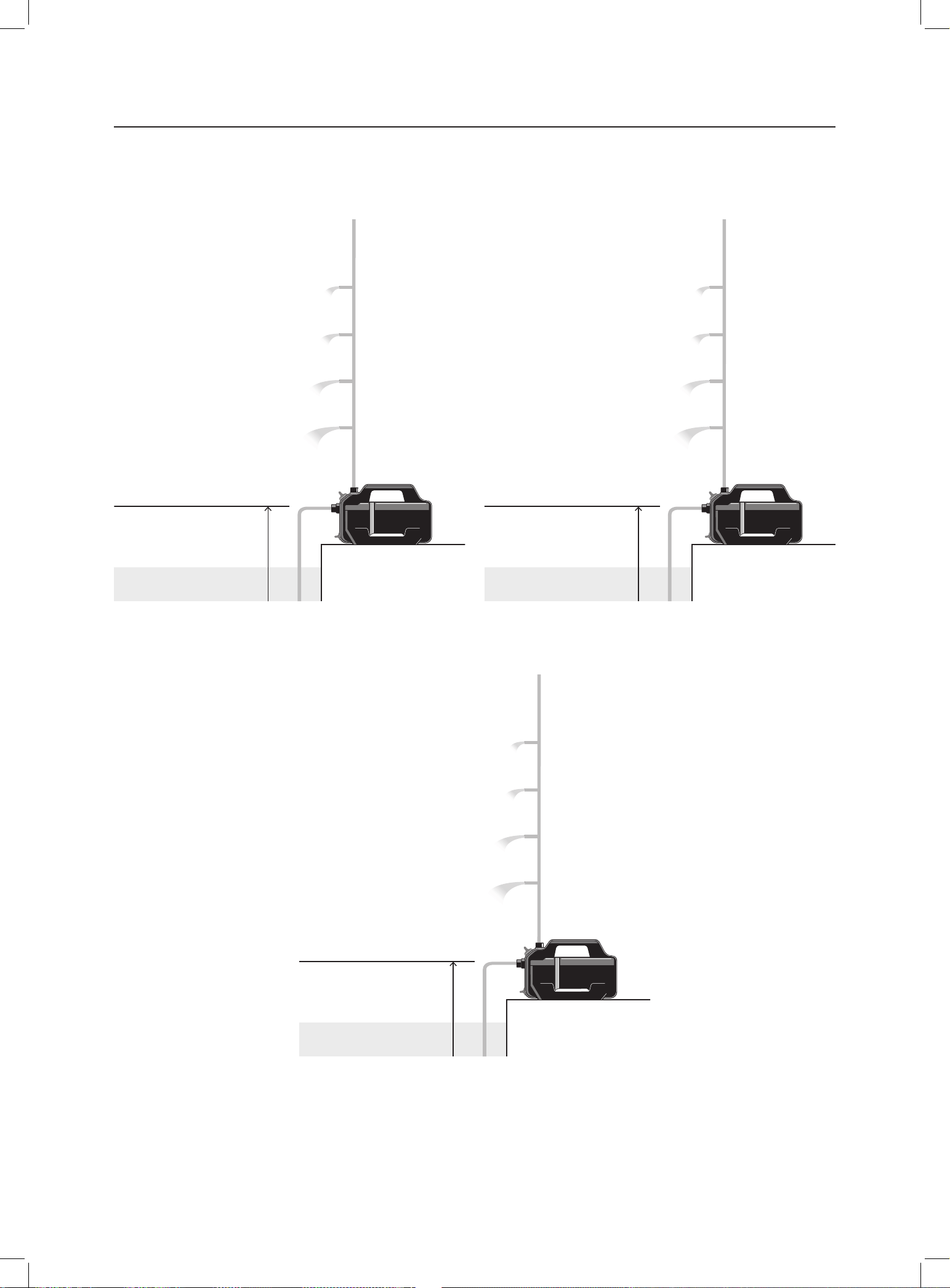
4. For suction heights exceeding 3 m: Fix the suction hose
2
additionally.
(e. g. by fastening it to a wooden post).
Therefore, the pump is relieved of the weight of the suction hose.
2.3. To connect the hose to the pressure side [ Fig. A7 ]
The connector on the pressure side
3
is equipped with a 33.3 mm (G 1")
external thread.
The connection pieces on the pressure side may only be tightened
by hand.
Optimised use of the pump capacity is achieved by connecting
19mm (3/4") hoses with:
• e. g. the GARDENA Pump Connection Set Art. 1752
• or by connecting 25 mm (1") hoses with the GARDENA Quick
Thread Coupling with female thread Art. 7109 / Quick Coupling
Hose Connector Art. 7103.
Hold or fix the pressure hose vertically to avoid kinking of the pressure
hose at the vertical pump outlet.
Lay the hose flat on the ground; avoid u-shaped elevations of the hose and
coiling it. In order to allow the air to escape optimally, lay out the pressure
hose completely and give it a rising course as seen from the pump.
g Connect the pressure hose
4
with the connector on the pressure
side
3
.
2.3.1 To connect the pressure hose via the GARDENA quick
connection system
19 mm (3/4") / 16 mm (5/8") and 13 mm (1/2") hoses can be connected via
the GARDENA Connection System.
Hose diameter Pump connection
13 mm (1/2") GARDENA Pump Connection Set Art. 1750
16 mm (5/8") GARDENA Tap Connector
GARDENA Hose Connector
Art. 18202
Art. 18216
19 mm (3/4") GARDENA Pump Connection Set Art. 1752
2.3.2 Only for Art. 9056: Parallel connection of pressure hoses:
When connecting more than one pressure hose in parallel, we recommend
the use of:
• e. g. the GARDENA 2- or 4-Channel Water Distributor
Art. 8193 / 8194
• or the GARDENA Twin-Tap Connector Art. 940.
These can be screwed directly onto the connector of the pressure side
3
.
3. OPERATION
DANGER!
Risk of injury!
Risk of injury due to accidental starting.
g Unplug the plug of the mains cable from the mains socket.
3.1. To start / To stop the pump [ Fig. O1 / O2 ]
CAUTION!
Dry-Running of the pump!
Make sure that the pump is filled with water up to the overflow
(min. 1.1 l) before each starting procedure.
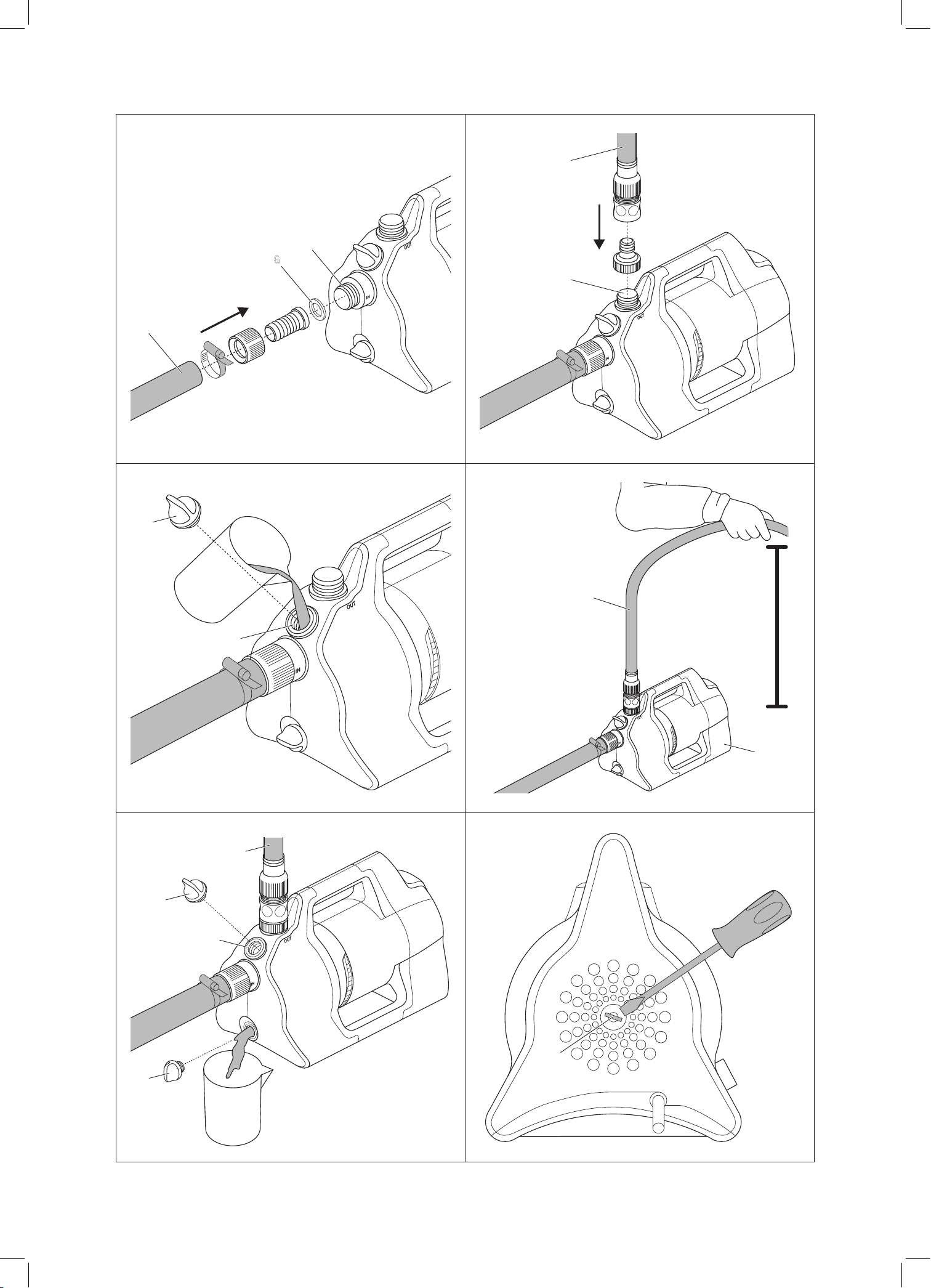
3.1.1 To start the pump
1. Connect the suction hose (In).
2. Disconnect the pressure hose (Out).
3. Unscrew the screw connection
5
on the filling opening
6
by hand.
4. Slowly fill in at least 1.1 l of water via the filler opening
6
until a stable
water level is reached at the level of the suction side connection
[ Fig. A4 ].
5. If a non-return valve is used: Fill the suction hose with water.
This speeds up the suction process.
6. Empty the residual water in the pressure hose
4
before connecting.
This allows the air to escape during the suction process.
7. After filling the pump: Connect the pressure hose (Out) to the pump.
8. Tighten the screw connection
5
on the filling opening
6
by hand
(do not use pliers).
9. Open any shut-off valves in the pressure line (connection devices,
water stop, etc.). All consumers must be opened to the max. possible
position.
6
10. Insert the plug of the mains cable into a mains socket.
11. For high suction heights: Lift and hold the pressure hose
4
at least
1.8 m vertically above the pump during the suction process.
12. Push the On / Off switch
7
to the position On.
The pump starts (the On/Off switch lights) and pumps the water after
the suction process.
The suction process can take up to 5 minutes.
If the pump does not pump water after 5 minutes
1. Push the On / Off switch
7
to the position Off.
The pump stops.
2. Let the pump cool down.
3. Search in the 6.2 Troubleshooting table for possible causes.
4. Start the pump again (see „3.1.1 To start the pump“).
3.1.2 To stop the pump
g Push the On/Off switch
7
to the position Off.
The pump stops.
3.2. Hints to pump
3.2.1 General tip on suction
The specified maximum self-priming height is only reached when the
pump is filled to the overflow via the filling opening and the pressure
hose
4
is held upwards during the priming process so that no water
can escape from the pump via the pressure hose
4
. Fill the pump before
hoses, fixed piping etc. are connected to the pump on the pressure side.
This ensures that the pump can be completely filled with water (1.1 l)
(air can escape).
The pump is to be filled with 1.1 l of water.
3.2.2 Silent operation
The pump is silent. This advantage can only be maintained with the
correct installation:
g Choose a low-vibration base (e. g. do not place on metal sheets or
plastic tanks).
3.2.3 Assembly of the prelter
If a prefilter is too long, it can be assembled in another position
(e. g. horizontally) instead of in the vertical position still below.
4. MAINTENANCE
DANGER!
Risk of injury!
Risk of injury due to accidental starting.
g Unplug the plug of the mains cable from the mains socket.
4.1. To clean the Pump:
DANGER!
Risk of injury!
Risk of injury and risk of damage to the product.
g Do not clean the product with water or with a water jet (in particular
high-pressure water jet).
g Do not clean with chemicals including petrol or solvents. Some can
destroy critical plastic parts.
The airflow slots must always be clean.
1. Clean the pump housing with a damp cloth.
2. Clean the airflow slots with a soft brush (do not use sharp objects).
4.2. To ush the pump
After pumping chlorinated water, the pump must be flushed.
1. Pump through lukewarm water (max. 35 °C), possibly adding a mild
cleaning agent (e. g. detergent) until the pumped water runs clear.
2. Dispose of the residues in accordance with local waste disposal
regulations.
5. STORAGE
To put into storage [ Fig. S1 ]
CAUTION!
Damage to the pump due to frost!
g Store the pump in a frost-free place.
The product must be stored away from children.
1. Unplug the plug of the mains cable from the mains socket.
2. Close any shut-off valves in the suction line.
3. Open any shut-off valves in the pressure line (accessories, water
stop, etc.).
Therefore the pressure line is depressurized.
4. Unscrew the screw fitting
5
of the filler neck
6
and the water drain
screw
8
by hand.
Therefore the pump is drained.
5. Tilt the pump in the direction of the drain (approx. 80°) so that the
pump empties completely.
6. Unscrew the suction hose and the pressure hose.
7. Tighten the screw connection
5
on the filling opening
6
and the
water drain screw
8
by hand (do not use pliers).
8. Clean the pump (see „4. MAINTENANCE“).
9. Store the pump in a dry, enclosed and frost-free place.
6. TROUBLESHOOTING
DANGER!
Risk of injury!
Risk of injury due to accidental starting.
g Unplug the plug of the mains cable from the mains socket.
6.1. To loosen the impeller [ Fig. T1 ]
An impeller blocked by dirt can be loosened.
g Turn the shaft of the impeller
9
clockwise with an insulated screw-
driver.
Therefore the blocked impeller is loosened.
6.2. Troubleshooting table
Problem Possible Cause Remedy
Pump is running,
but the suction action
doesn’t take place
Leaky or damaged suction line
[Fig. A2].
Check the suction line
for damage and seal so
is airtight.
Pump sucks in air at a con-
nection point [Fig. A2].
Seal the suction side
con nections airtight.
No water available in
the cistern,water tank,
water pipe, etc.
Make sure that the water
supply is on the suction
side.
Pump was not lled with water
[Fig. A4].
Fill the pump
(see „3.1.1 To start the
pump“).
Water escapes during the
suction process via the
pressure hose.
1. Fill the pump again.
2. Hold up the pressure hose.
3. Start the pump again
(see „3.1.1 To start the
pump“).
Pump is running,
but the suction action
doesn’t take place
Absolutely vacuum-resistant connection is achieved by
using GARDENA Suction Hoses (see „8. ACCESSORIES / SPARE
PARTS“).
Screw tting on the ller neck
is leaking [ Fig. A2 ].
Check the seal (replace
ifnecessary) and tighten
the screw tting by hand
(do not use pliers).
Air cannot escape, since the
delivery line is closed or
remaining water is in the
pressure hose.
Open any shut-o val-
ves (e. g. nozzle) in the
delivery line, or drain the
pressure hose.
Garden pump
Unit Value
(Art. 9050)
Value
(Art. 9054)
Value
(Art. 9056)
Power cable m
1.5
(H07RN-F)
1.5
(H07RN-F)
1.5
(H07RN-F)
Weight without cable
(approx.)
kg 5.6 5.8 6.3
Sound pressure level L
pA
Distance: 1 m
5 m
10 m
dB
64
50
44
63
49
43
65
51
45
Sound power level L
WA
1)
:
measured / guaranteed
Uncertainty k
WA
dB (A)
73 / 75
2.52
71 / 74
2.58
73 / 75
2.20
Max. media temperature °C 35 35 35
Measuring process complying with:
1)
RL 2000/14/EU
8. ACCESSORIES / SPARE PARTS
GARDENA Suction Hoses Kink-proof and vacuum-proof, optionally available by the metre
Art. 1720 / 1721 (19 mm (3/4") / 25 mm (1")) without connecting
ttings or in xed length Art. 9090 / 9091 complete with connect-
ing ttings.
GARDENA Suction Hose
Fitting
For connection on the suction side. Art. 1723 / 1724
GARDENA Pump Connection
Set
For connection on the delivery side. Art. 1750 / 1752
GARDENA Suction Filter
with backflow preventer
To equip suction hoses with backow
preventer sold by the meter.
Art. 9093
GARDENA Pump Preliminary
Filter
Recommended for pumping sandy water. Art. 1730 / 1731
GARDENA Bore Hole Suction
Hose
For vacuum-resistant connection of the pump
to boreholes or pipe networks. Length 0.5 m.
With 33.3 mm (G1) female thread at both ends.
Art. 1729
GARDENA Floater for floating
suction
Can be attached to suction lter 9090 / 9092
/ 9093 and enables dirt-free suction under the
surface of the water.
Art. 9094
GARDENA Quick coupling For pressure-side connection of 1" pressure
hoses.
Art. 7109 / 7103
9. DISPOSAL
Disposal of the pump
(according to Directive 2012/19/EU)
The product must not be disposed of to normal household waste.
It must be disposed of in line with local environmental regulations.
IMPORTANT!
Dispose of the product through or via your local recycling collection
centre.
7
Problem Possible Cause Remedy
Air cannot escape because the
pressure hose is coiled.
1. Lay out the pressure hose
straight along its entire
length.
2. Lay the hose from the pump
outlet upwards.
3. Do not kink the pressure
hose at the pump outlet.
4. Open all consumers maxi-
mum.
Suction time of 5 min. was
not waited for.
Wait up to 5 minutes for
the pump to pump water.
Suction lter or backow
preventer in the suction hose
are clogged.
Clean the suction lter or
the back ow preventer.
The end of the suction hose is
not in the water [Fig. A5].
Submerge the end of the
suction hose deeper in
the water.
Suction height is too high
[Fig. A5].
Reduce the suction
height.
In case of any other diculties concerning the suction action,
use GARDENA Suction Hoses with Backow Preventer
(see „8. ACCESSORIES / SPARE PARTS“). Fill the pump with
water before starting it.
Pump does not start,
or stops suddenly during
operation
Thermal switch has turned
the pump o because of over-
heating.
Let the pump cool down,
empty the pump and ll
it again.
Observe the max. media
Temperature (35 °C).
No power supply to the pump. Check the fuses and
electrical plug connec-
tions.
RCD has triggered
(residual current).
Unplug the plug from
the mains socket and
contact
the GARDENA Service.
Pump is not switched on. Push the On / O switch
to the
position On.
Pump is running,
but the delivery
drops suddenly
The end of the suction hose is
not in the water [Fig. A5].
Submerge the end of the
suction hose deeper in
the water.
Suction lter or backow
preventer in the suction hose
are clogged.
Clean the suction lter or
the back ow preventer.
No water available in the
cistern, water tank, water
pipe, etc.
Make sure that the water
supply is on the suction
side.
Suction line is leaking [Fig. A2]. Eliminate the leak.
Impeller is blocked. Loosen the impeller.
Pressure hose is kinked. Lay the pressure hose
without kinks and do not
kink the pressure hose at
the pump outlet.
NOTE:
Repairs must only be done by the GARDENA service departments or
specialist dealers approved by GARDENA.
g For any other malfunctions please contact the GARDENA service
department.
7. TECHNICAL DATA
Garden pump
Unit Value
(Art. 9050)
Value
(Art. 9054)
Value
(Art. 9056)
Rated power W 550 600 650
Mains voltage V (AC) 220 – 240 220 – 240 230
Mains frequency Hz 50 50 50
Max. delivery capacity l/h 4100 4200 4300
Max. pressure /
Max. delivery head
bar /
m
3.6
36
3.9
39
4.3
43
Max. self-priming suction
height
m 8 8 8
Permitted internal pressure
(delivery side)
bar 6 6 6
10. PERFORMANCE CHARACTERISTICS
8
20 m
10 m
5 m
max.
36 m
30 mmax. 270 l/h
max. 1.190 l/h
max. 2.880 l/h
max. 3.650 l/h
max. 8 m
20 m
10 m
5 m
max.
39 m
30 mmax. 430 l/h
max. 1.500 l/h
max. 3.110 l/h
max. 3.730 l/h
max. 8 m
4100 Silent Art. 9050
4200 Silent Art. 9054
30 m
20 m
10 m
max.
43 m
40 mmax. 108 l/h
max. 820 l/h
max. 2.060 l/h
max. 3.270 l/h
max. 8 m
4300 Silent Art. 9056
11. WARRANTY / SERVICE
11.1. Service
The current contact information for our service department can be found online: www.gardena.com/contact
11.2. Warranty
Husqvarna provides a manufacturer’s warranty against faulty workmanship in manufacture and/or defective components to initial purchaser for each new
GARDENA branded product produced by Husqvarna and purchased in Australia. To make a valid claim under this manufacturer’s warranty the product
and proof of purchase must be provided to the retailer. This warranty does not cover damage caused by misuse, neglect, adjustments and/or modica-
tions by the consumer or normal wear and tear, the costs of shipping and handling, travel expense, lost time, or pickup and delivery.
11.2.1 Australia
Our goods come with guarantees that cannot be excluded under the Australian Consumer Law. You are entitled to a replacement or refund for major fai-
lure and for compensation for any other reasonably foreseeable loss or damage. You are also entitled to have the goods repaired or replaced if the goods
fail to be of acceptable quality and the failure does not amount to a major failure.
Husqvarna Australia Pty Ltd (ABN 45 115 475 619) 4 Pioneer Avenue, Tuggerah NSW 2259. Tel: 1300 804 213.
11.2.2 New Zealand
This manufacturer’s warranty is in addition to the rights and remedies provided by the New Zealand Consumer Guarantees Act. Husqvarna New Zealand
Ltd (Company No. 111861) 51 Aintree Avenue, Airport Oaks, Manukau 2022. Tel: 09 920 2410. Made in Germany to GARDENA's specications.
12. DECLARATION OF CONFORMITY
EC Declaration of Conformity The undersigned hereby certies as the authorized representative of the manufacturer, GARDENA Germany AB, PO Box 7454, S-103 92,
Stockholm, Sweden, that, when leaving our factory, the unit(s) indicated below is / are in accordance with the harmonised EU guidelines, EU
standards of safety and product specic standards. This certicate becomes void if the unit(s) is / are modied without our approval.
Conformity Assessment procedure according to 2000/14/EC Art.14 Annex V, Noise level: measured / guaranteed
(1)
Deposited Documentation
(2)
| Year of CE marking: 2022 | Ulm, 01/11/2022
Garden pump Art. No.
4100 Silent
4200 Silent
4300 Silent
9050
9054
9056
(1) 73 dB (A) / 75 dB (A)
71 dB (A) / 74 dB (A)
73 dB (A) / 75 dB (A)
2014/35/EU
2014/30/EU
2011/65/EU
2000/14/EG
EN ISO 12100
EN 60335-1
EN 60335-2-41
(2) GARDENA Manufacturing GmbH
M. Jäger
Hans-Lorenser-Str. 40
89079 Ulm / Germany
Martin Lienhard,
Senior Vice President,
Business Unit Electric and
Battery
9

10
9050-52.960.02/0225
© GARDENA Manufacturing GmbH
D-89079 Ulm
https://www.gardena.com
Australia
Husqvarna Australia Pty. Ltd.
Locked Bag 5
Central Coast BC
NSW 2252
Phone: (+ 61) (0) 2 4352 7400
customer[email protected]
New Zealand
Husqvarna New Zealand Ltd.
PO Box 76-437
Manukau City 2241
Phone: (+64) (0) 9 9202410
support[email protected].nz