
70
52
49
50
46
48
(2x)
45
47
6
5
7
11
10
44
(4x)
4
18
65
41
(2x)
54
(2x)
53
(2x)
58
(4x)
19
(6x)
1
9
(2x)
8
61
17
12
(4x)
12
(8x)
3
2
68
63
64
71
51
(7x)
76
(2x)
75
52 70
71
82
41 53
54 65
81
44 45 46 47
48 49 50 51
83
17 18
19
84
3 4
12
85
1 2
8 9
12
86
8 9
88
5 6
90
75 76
91
58 61
93
10 11
97
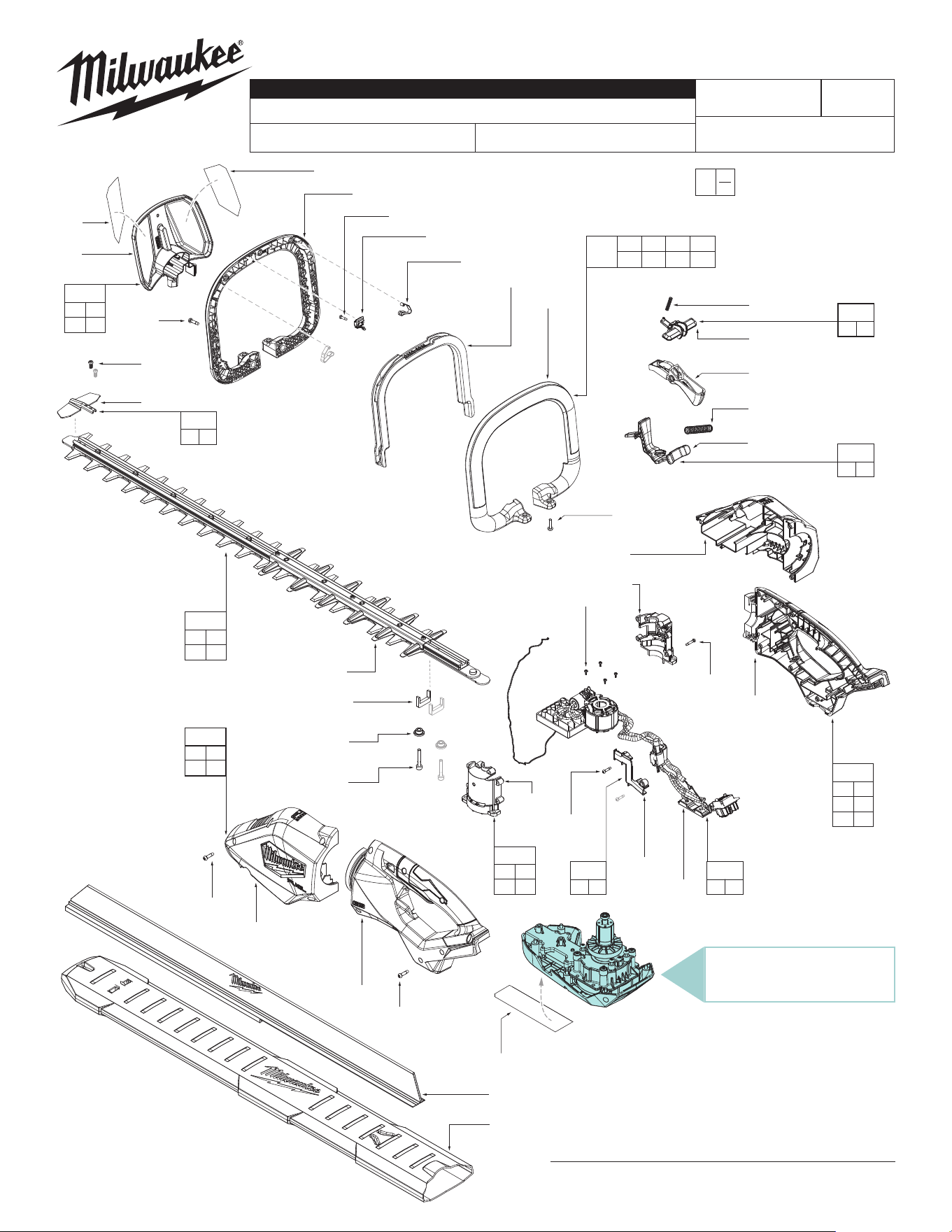
BULLETIN NO.
54-49-2725
SERVICE PARTS LIST
CATALOG NO. 3034-20
REVISED BULLETIN
SPECIFY CATALOG NO. AND SERIAL NO. WHEN ORDERING PARTS
M18 FUEL™ 30" HEDGE TRIMMER
SERIAL NO.
DATE
Oct. 2024
WIRING INSTRUCTION
P67A
See Page 6
0
00
EXAMPLE:
Component Parts (Small #)
Are Included When Ordering
The Assembly (Large #).
SERVICE BOM
- info on page 2 -
MILWAUKEE TOOL
l
www.milwaukeetool.com
13135 W. LISBON RD., BROOKFIELD, WI 53005
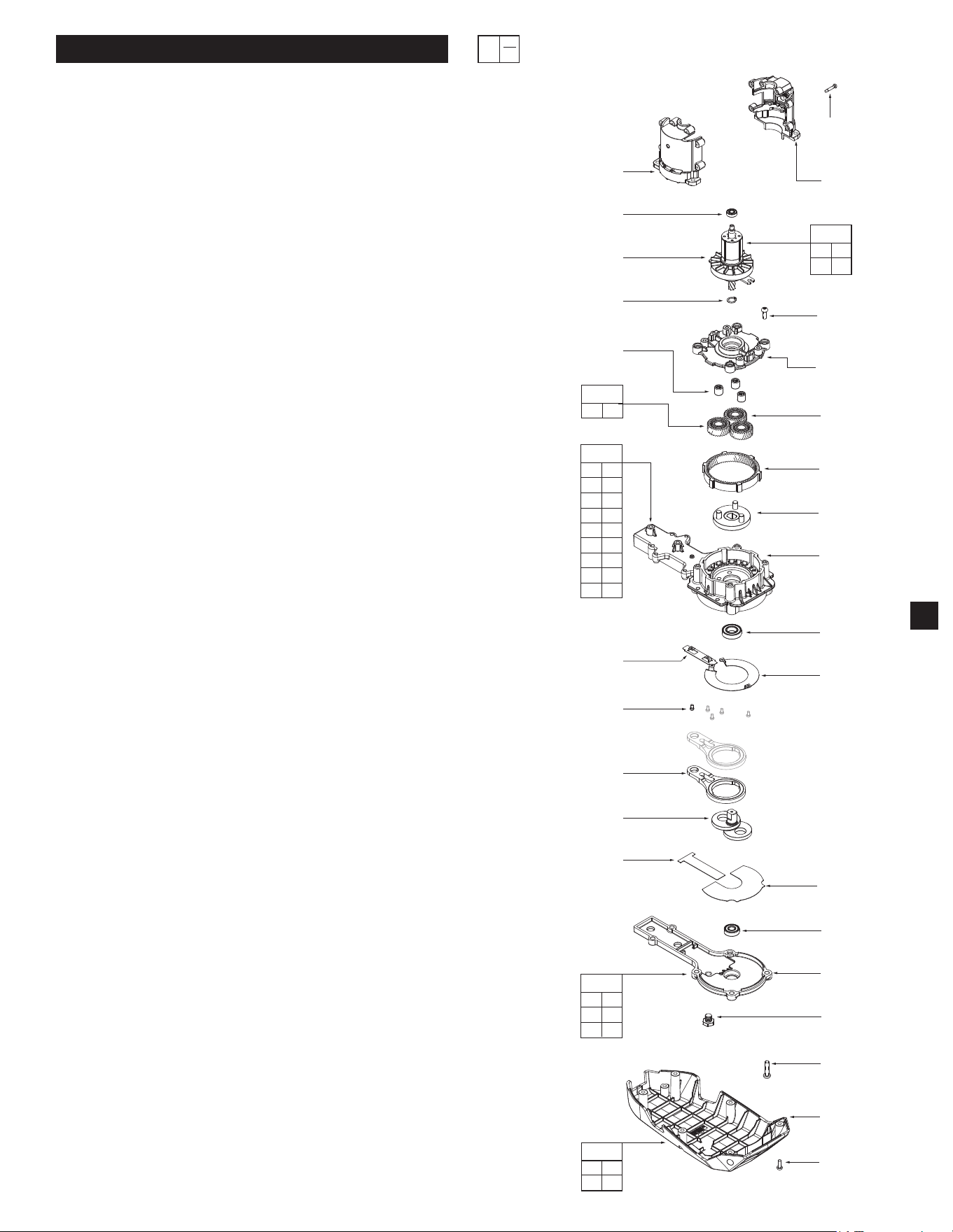
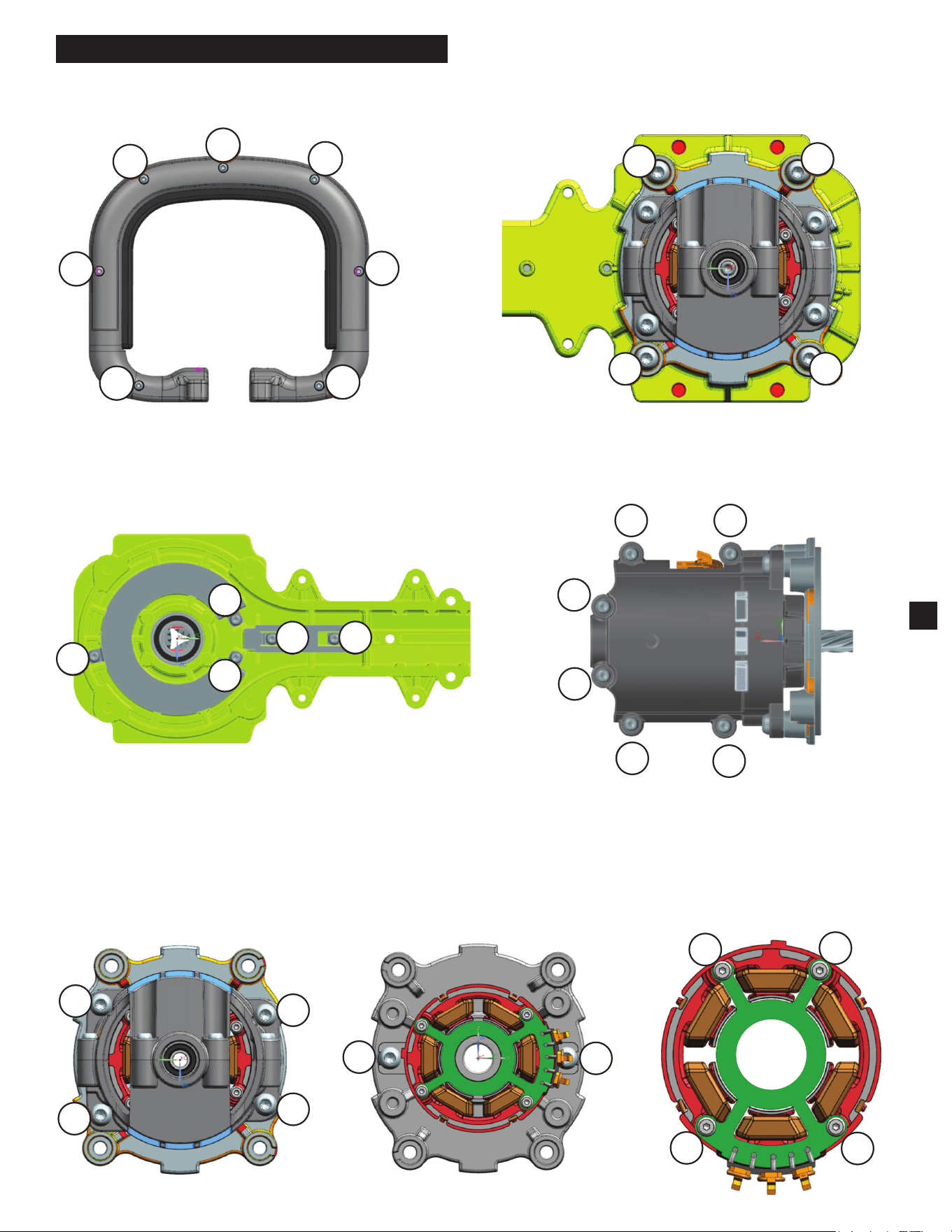
Drwg. 1
Rotor and Gearcase
Exploded on Page 2
FIG. SERVICE NOTES
68,70
A clean, dry surface is essential for proper performance
71
for any adhesive system. The area intended for
application of any adhesive label or nameplate must be
prepared by cleaning with isopropyl alcohol. The
solvent is to be applied with a clean, lint free applicator
and the surface allowed to dry before applying the
label or nameplate.
29
30
17
13
14
20
24
(3x)
21
(10x)
22
25
(3x)
26
27
28
31
32
(5x)
34
(2x)
33
36
35
37
38
39
40
(6x)
42
43
(8x)
19
(6x)
18
42 43
68
89
35 36
37 38
39 40
87
24 25
95
13 14
20 21
94
13 14
17 18
19 20
21 22
24 25
26 27
28 29
30 31
32
96
FIG. PART NO. DESCRIPTION OF PART NO. REQ.
1 --------------- Back Handle Support (1)
2 --------------- Back Handle Cover (1)
3 --------------- Front Handle Cover (1)
4 --------------- Front Handle Support (1)
5 42-42-0011 Safety Button (1)
6 --------------- Spring (1)
7 45-72-9362 Trigger (1)
8 --------------- Wire Cover (1)
9 06-82-1080 M3 x 14mm Pan Hd Screw (2)
10 --------------- Finger Clearance Slide (1)
(Rotation Lock Button)
11 --------------- Spring for Slide (1)
12 --------------- M4 x 16mm PH Torx T-20 B Screw (12)
13 --------------- Ball Bearing (1)
14 --------------- Rotor (1)
17 --------------- Motor Housing Support (1)
18 --------------- Motor Housing Cover (1)
19 06-82-6351 M3 x 16mm PH Torx T-10 B Screw (6)
20 34-80-1120 Retaining Ring (1)
21 --------------- M4 x 12mm PH Torx T-20 Screw (10)
22 --------------- Motor Mount (1)
24 --------------- Needle Bearing (3)
25 --------------- Planet Gear (3)
26 --------------- Ring Gear (1)
27 --------------- Carrier (1)
28 --------------- Gearcase (1)
29 --------------- Rear Spindle Ball Bearing (1)
30 --------------- Wear Plate Upper Gearcase (1)
31 --------------- Wear Plate Lower Gearcase (1)
32 05-74-0144 M3 x 5mm M Screw (5)
33 14-09-6147 Crankshaft (1)
34 30-94-5841 Connecting Rod (2)
35 --------------- Upper Wear Plate Gearcase Cover (1)
36 --------------- Lower Wear Plate Gearcase Cover (1)
37 --------------- Ball Bearing (1)
38 --------------- Gearcase Cover (1)
39 05-85-0080 M8 x 1.25 M Screw (1)
40 05-78-0033 M5 x 20mm M Screw (6)
41 45-06-4572 Felt Seal (2)
42 --------------- Bottom Front Cover (1)
43 06-82-0186 M4 x 10mm PH Torx T-20 M Screw (8)
44 --------------- M4 x 16mm PH Torx T-20 M Screw (4)
45 --------------- Bail Handle Support (1)
46 --------------- Gasket For Switch (1)
47 06-82-1087 M3 x 12mm PH Torx T-10 B Screw (1)
48 --------------- Spring Clip (1)
49 --------------- Trigger Bail Handle (1)
50 --------------- Bail Handle Cover (1)
51 --------------- M4 x 16mm PH Torx T-20 B Screw (7)
52 --------------- Hand Guard (1)
53 06-82-2259 M5 x 30mm Hexagon Rec. M Screw (2)
54 42-40-0019 Bushing (2)
58 05-88-0106 M2 x 5.5mm CH Torx T-8 PT Screw (4)
61 --------------- PCBA and Stator (1)
63 31-01-6812 30 inch Sweep Attachment (1)
64 31-01-4809 30 inch Sheath (1)
65 --------------- 30 inch Blade Assembly (1)
68 12-20-1920 Service Nameplate (1)
70 10-22-1979 Warning Label (1)
71 10-22-1980 Warning Label (1)
75 --------------- Tip Guard (1)
76 --------------- M4 x 10mm PHTorx T-20 M Screw (2)
81 42-41-0942 30 inch Blade Kit (1)
82 14-32-5306 Hand Guard Kit (1)
83 14-34-6251 Bail Handle Kit (1)
84 14-50-2881 Motor Insulator Kit (1)
85 14-34-6252 Handle Cover Kit (1)
86 31-50-6581 Housing Kit (1)
87 31-40-5248 Gearcase Cover Kit (1)
88 31-15-2482 Wire Cover Kit (1)
89 31-15-2481 Bottom Cover Kit (1)
90 42-42-6478 Safety Button Kit (1)
91 43-54-8521 Blade Tip Guard Kit (1)
93 14-20-5985 Electronics Assembly (1)
94 16-01-5339 Rotor Assembly (1)
95 14-46-2558 Bearing Assembly (1)
96 23-30-4626 Rotor / Motor Assembly (1)
97 45-72-0920 Slide Kit (1)
SERVICE BILL OF MATERIAL (BOM) LISTING
EXAMPLE:
Component Parts (Small #)
Are Included When Ordering
The Assembly (Large #).
0
00
2
SCREW TORQUE SPECIFICATIONS
SEAT TORQUE
FIG. PART NO. DESCRIPTION OF FASTENER WHERE USED (kgf-cm) (lb-in)
9 06-82-1080 M3 x 14mm Pan Hd. Screw Wire Cover 6 ± 1 5 ± 0.9
12 --------------- M4 x 16mm Pan Hd. Torx T-20 B Screw Back and Front Handle Support 9 ± 1 8 ± 0.9
19 06-82-6351 M3 x 16mm Pan Hd. Torx T-10 B Screw Motor Housing 9 ± 1 8 ± 0.9
21 --------------- M4 x 12mm Pan Hd. Torx T-20 Screw Motor Housing Mount 24 ± 3 21 ± 2.6
21 --------------- M4 x 12mm Pan Hd. Torx T-20 Screw Bearing Plate / Motor Mount 30 ± 3 26 ± 2.6
32 05-74-0144 M3 x 5mm M Screw Wear Plate (item 30 &31) 8 ± 1 7 ± 0.9
39 05-85-0080 M8 x 1.25 M Screw Grease Port Plug 60 ± 6 52 ± 5
40 05-78-0033 M5 x 20mm M Screw Gearcase Cover 60 ± 6 52 ± 5
43 06-82-0186 M4 x 10mm Pan Hd. Torx T-20 M Screw Bottom Front Cover / Hand Guard 12 ± 1 10 ± 0.9
44 --------------- M4 x 16mm Pan Hd. Torx T-20 M Screw Bail Handle 24 ± 3 20 ± 2.6
47 06-82-1087 M3 x 12mm Pan Hd. Torx T-10 B Screw Zippy Switch 3.5 ± 0.5 3 ± 0.4
51 --------------- M4 x 16mm Pan Hd. Torx T-20 B Screw Bail Handle Assembly 18 ± 2 15 ± 1.7
53 06-82-2259 M5 x 30mm Hexagon Rec. M Screw Blade Gearcase 90 ± 9 78 ± 7.8
58 05-88-0106 M2 x 5.5mm Cap Hd. Torx T-8 PT Screw Hall Board 3 ± 0.5 2.6 ± 0.4
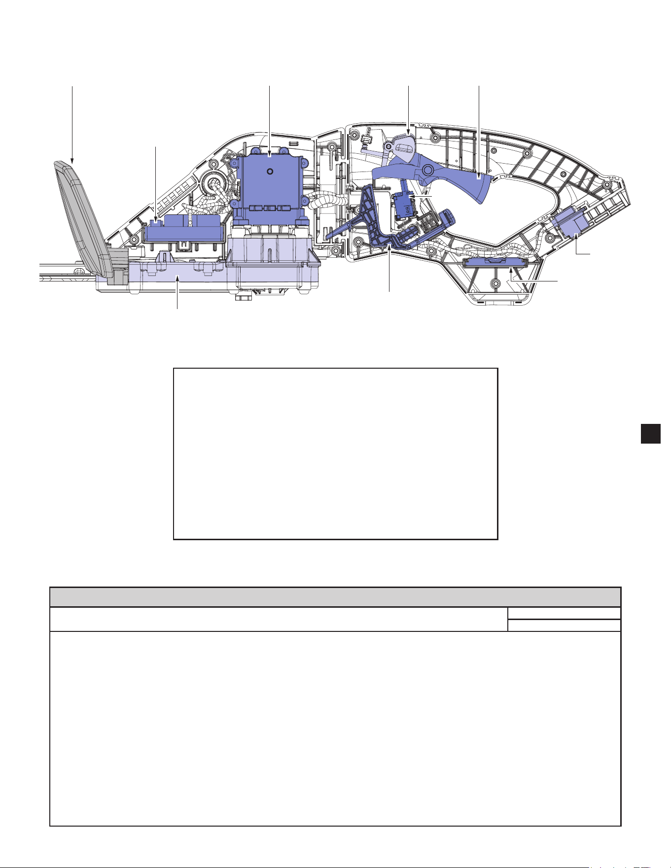
Terminal
Block
Safety Button Trigger
Finger
Clearance
Slide
Fuse
Holder
Control Board
Motor
Gearcase
Hand Guard
Switch
WARNING
• Take notice of wire routing and position in wire guides and
traps while dismantling tool.
• Be sure that all components of the electronics kit are seated
rmly and squarely in housing recesses.
• Avoid pinched wires, be sure all wires and sleeves are
pressed completely down in wire guides and traps.
• Prior to installing housing cover onto handle support,
be sure that there are no interferences.
• Be sure to check for proper functionality of switches and
buttons after housing halves have been secured.
3
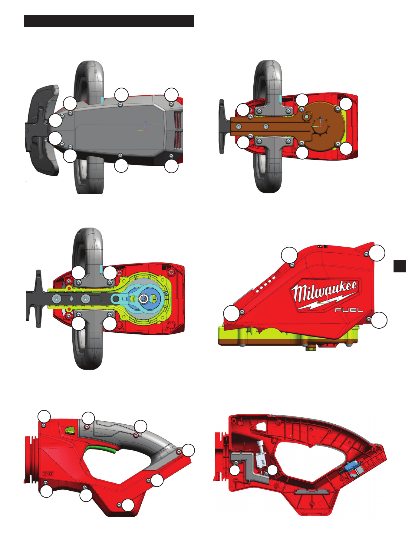
SCREW TIGHTENING SEQUENCE
STEP 1 - Bottom Front Cover STEP 2 - Gearcase Cover
STEP 3 - Bail Handle Bottom STEP 4 - Front Handle Cover
STEP 5 - Back Handle Cover STEP 6 - Back Handle Support
1
2
3
45
6
7
8
1
2
3
4
5
6
1
2
3
4
1
2
3
4
1
2
3
4
5
6
7
8
1
2
4
SCREW TIGHTENING SEQUENCE - Continued
STEP 7 - Bail Handle
STEP 9 - Upper & Lower Wear Plates
STEP 8 - Gearcase Cover
STEP 10 - Motor Housing
1
2
3
4
5
6
7
1
2
3
4
1
2
5
4
3
1
2
3
4
5
6
STEP 11
- Motor Housing
STEP 12
- Motor Housing
STEP 13
- Stator
2
3
4
1
2
1
2
3
4
1
5
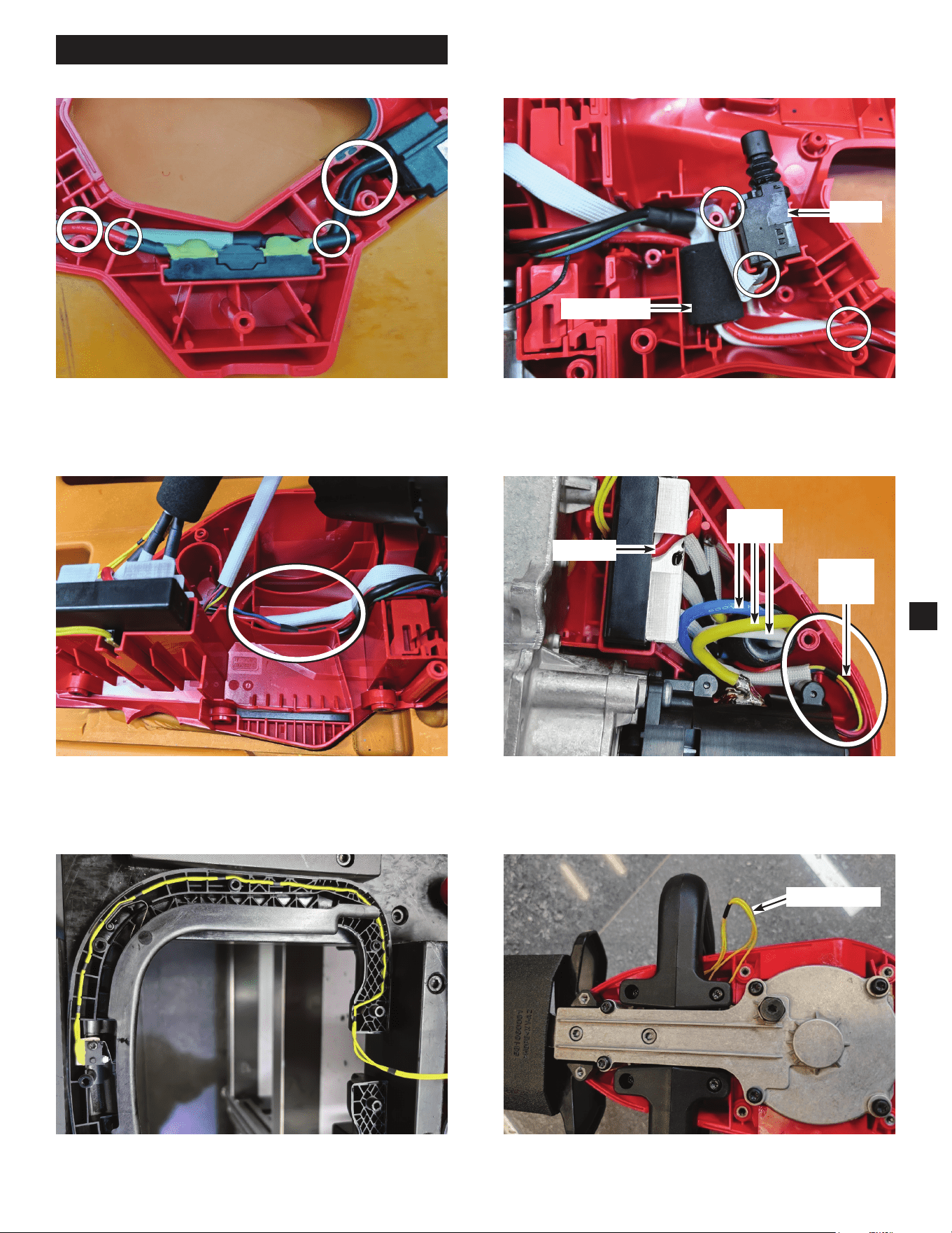
WIRING INSTRUCTIONS
The fuse and holder t into slot as shown above.
Be sure to t wires into guides and traps.
Fit the trigger switch and ferrite core into housing as
shown above, securing the wires into traps.
SWITCH
FERRITE CORE
The stator PCB wires should go through rib traps as
shown. Keep the red wire as far away from the three
stator wires as shown.
STATOR
PCB
WIRES
RED WIRE
STATOR
WIRES
Wires should be located at the bottom of the housing
support as shown.
Yellow wires must be seated in the slots of bail handle as
shown above.
Pull the yellow wires out before assembling the bail
handle.
YELLOW WIRES
6
Gear case grooves
to capture felt seal
Eccentric
Surface ‘A’
Connecting
Plate (34a)
Connecting
Plate (34b)
Eccentric
Surface ‘B’
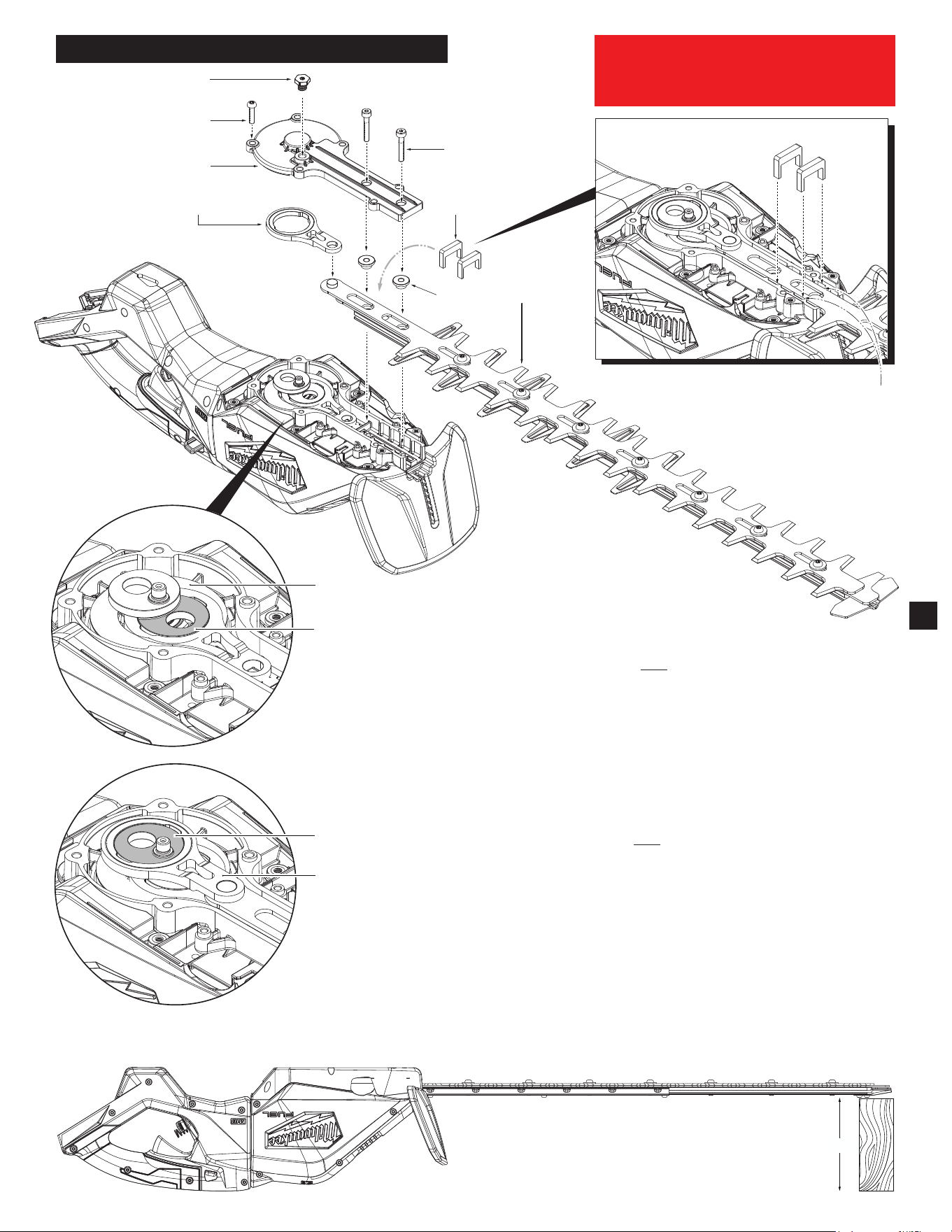
NOTE:
The service
replacement blade
assembly (81) is shipped
in a clear poly sleeve and
cardboard. It is recommended
to keep the cutting blade portion
of assembly in the poly sleeve/card-
board for safe handling during installation.
39
40
(6x)
38
34b
54
(2x)
41
(2x)
54(2x)
81
3.50"
7
Support the tool body so the bottom of
the tool is parallel with the work surface
BLADE REPLACEMENT INSTALLATION
INSTALLING REPLACEMENT BLADE ASSEMBLY (Model 3033-20 Shown)
• Remove battery pack
• Be sure top of Connecting Plate (34a) is ush with surface 'A' of the eccentric on the
Gear/Crank Shaft (33).
• Install new Blade Assembly (81) onto connecting plate (34a) as shown by placing the
hole of the blade assembly over the lug on the connecting plate.
• As an aid to keeping the connecting plate (34a) ush to the 'A' surface of the ec-
centric, support the tool housing on one end being sure the bottom of the gear case is
parallel with the work surface. Place a 3-1/2" wood block on the other end under the tip
of the replacement blade assembly, see illustration below.
• Place Connecting Plate (34b) over the bearing and onto the eccentric of the Gear/
Crank Shaft (33). Place the lug of connecting plate (34b) into the hole of the blade
assembly.
NOTE: An instrument such as a nail or small screwdriver may have to be inserted into
the exhaust vent to rotate the fan so the eccentric can turn and line up the hole with
the lug. Be sure eccentric surface 'B' is ush with the top surface of connecting plate
(34b).
• Place Felt Seal (41) over the blade assembly. Tuck each end down into grooves on
gear case.
• Place a light coating of lubrication onto the Bushings (54) and place onto slots of blade
assembly.
• Place a drop of red locking sealant onto the threads of screws (53). Insert screws
through the bushings and secure to the gear case.
• Place Gear Case Cover (38) onto gear case and secure with six screws (40).
• Place Bottom Front Cover (42) over gear case cover and secure with eight screws
(43). See page 2 for visual of items 42 and 43.
• Install battery and check for functionality.
ALWAYS REMOVE BATTERY PACK
BEFORE PERFORMING ANY
MAINTENANCE REPAIRS
8
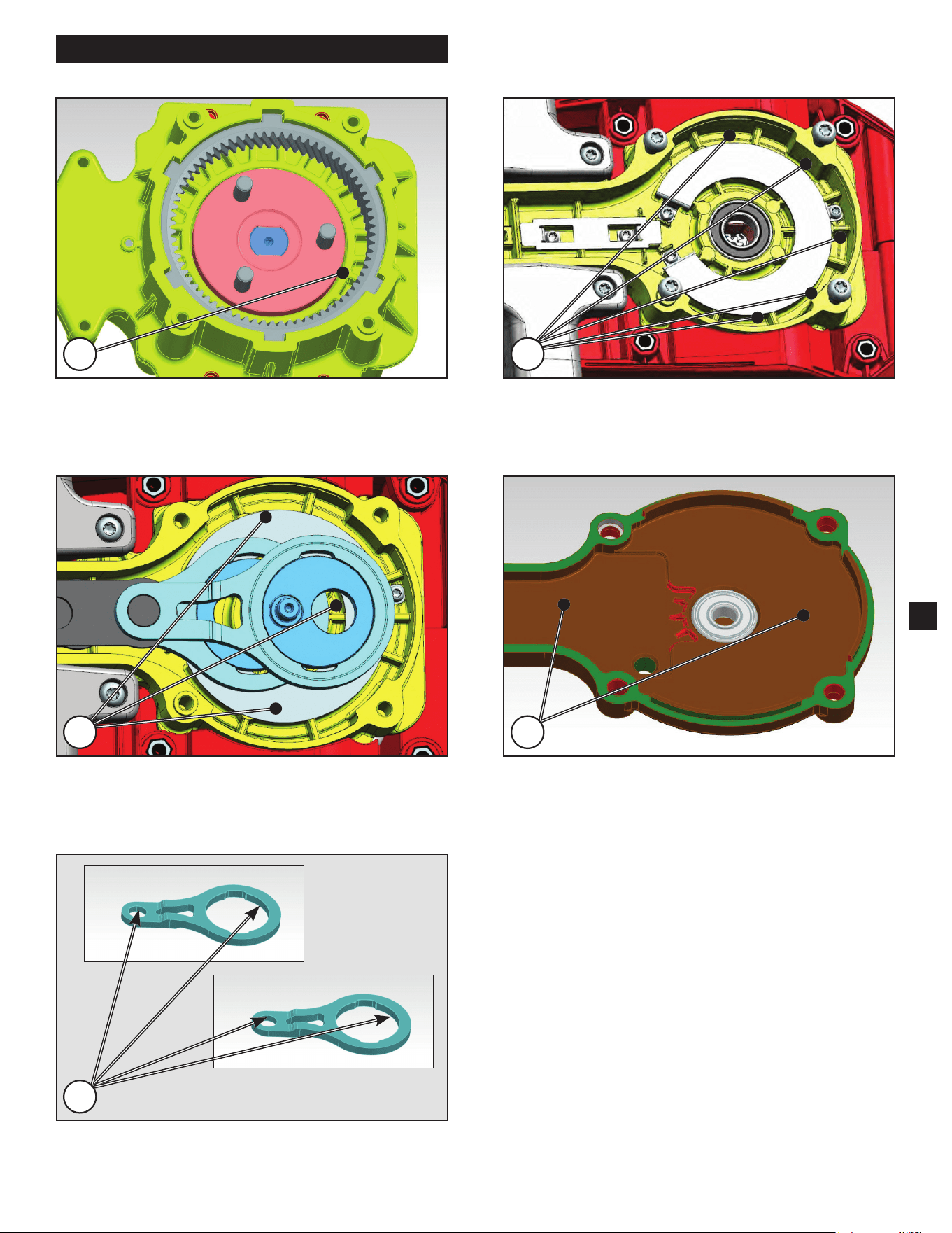
LUBRICATION INSTRUCTIONS
1) Apply approximately 15 grams of DECH 5157 grease
onto the prole of the gear as shown above.
2) Apply approximately 9 grams of DECH 5157 grease
as shown above and connect Rod Surface (Low) and
Wear Plate Upper Gearcase (30).
21
3) Apply approximately 9 grams of DECH 5157 grease
as shown above and connect Rod Surface (Low) and
Blade Groove.
3
4) Apply approximately 2 grams of DECH 5157 grease
as shown above and connect Wear Plate (35) and
Gearcase Cover (36).
4
5) Apply approximately 1 gram of DECH 5157 grease as
shown to EACH of the inner rings of the Connecting
Rods (34a & 34b).
5