
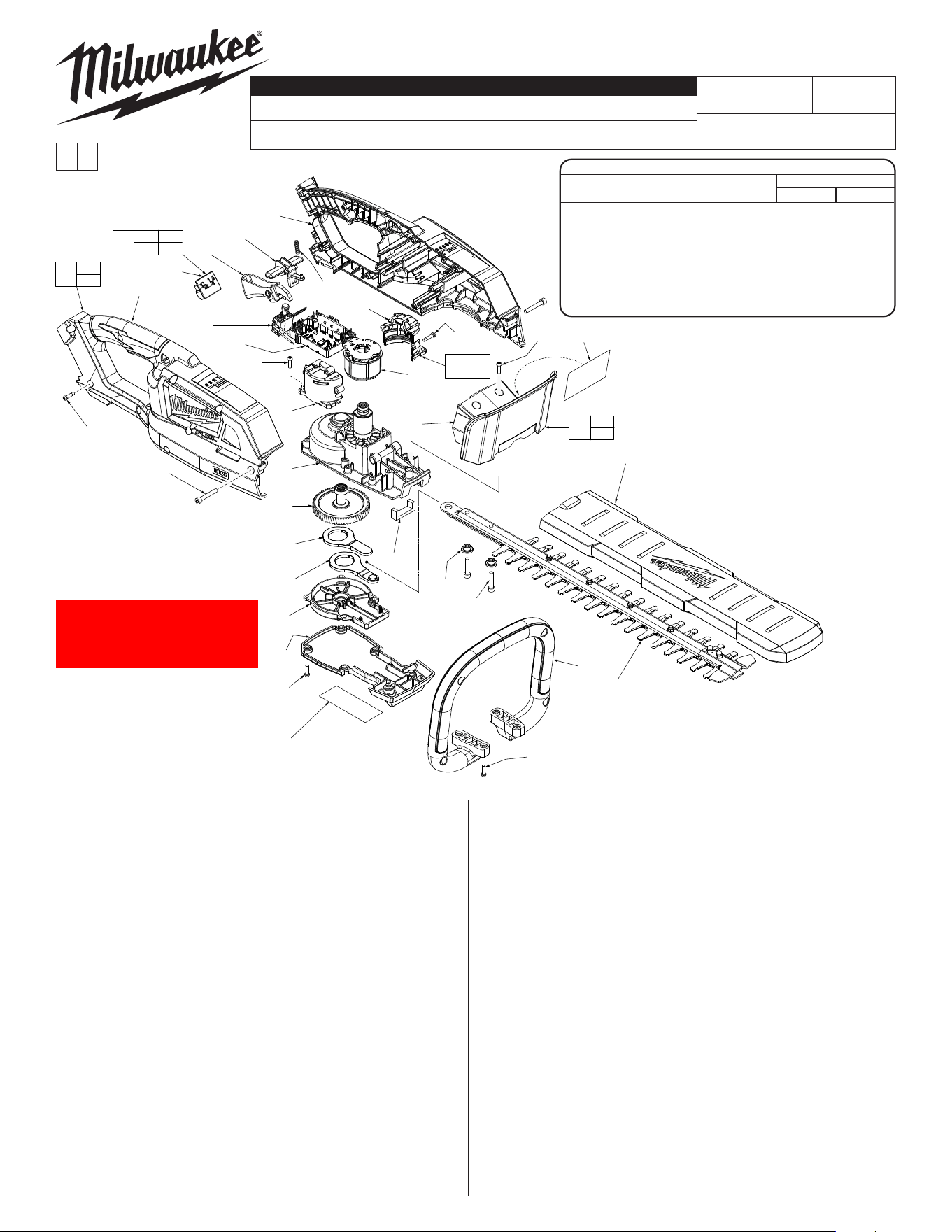
M18™ FUEL™ 18" HEDGE TRIMMER
3001-20
M42A
54-49-2705
See Page 3
Sept. 2021
REVISED BULLETIN
SERVICE PARTS LIST
BULLETIN NO.
WIRING INSTRUCTION
DATE
SPECIFY CATALOG NO. AND SERIAL NO. WHEN ORDERING PARTS
CATALOG NO.
STARTING
SERIAL NO.
EXAMPLE:
Component Parts (Small #)
Are Included When Ordering
The Assembly (Large #).
0
00
FIG. PART NO. DESCRIPTION OF PART NO. REQ.
1 42-26-0026 18" Blade Assembly 1
2 42-40-0019 Bushing 2
3 05-75-0012 M5 x 0.8 x 30, 4mm Hex Cap Screw 2
4 --------------- Hand Guard 1
5 43-62-0016 Bail Handle 1
6 31-15-0032 Gear Case Cover 1
7 05-88-1210 M4 x 0.7 x 14 Pan Hd. T-20 Machine Screw 16
8 42-92-0009 Gear Cover 1
12a 42-86-0101 Connecting Plate 1
12b 42-86-0101 Connecting Plate 1
23 --------------- Right Motor Housing Insulator - Support 1
24 --------------- Left Motor Housing Insulator - Cover 1
25 06-82-3006 M4 x 1.4 x 18 Pan Hd. ST T-20 Security Scr 4
26 14-20-0036 Electronic Assembly 1
26a --------------- Battery Connector Block Assembly 1
26b --------------- Switch Assembly 1
26c --------------- PCBA 1
26d --------------- Stator Assembly 1
28 40-50-4520 Lock-OSpring 1
29 05-74-0480 M5 x 0.8 x 25, 4mm Hex Cap Screw 2
30 42-42-0011 Lock-OButton 1
31 31-92-0016 Switch Trigger 1
32 --------------- Right Housing Assembly - Cover 1
33 --------------- Left Housing Assembly - Support 1
34 05-88-1200 M4 x 1.4 x 16 Pan Hd. ST T-15 Screw 8
MILWAUKEE TOOL
l
www.milwaukeetool.com
13135W.LisbonRoad,Brookeld,WI53005
Drwg. 1
FIG. PART NO. DESCRIPTION OF PART NO. REQ.
35 49-62-0115 18" Blade Sheath 1
36 12-20-0316 Service Nameplate 1
37 10-20-1041 Caution Label 1
38 45-06-0026 Felt Seal 1
40 31-44-2726 Housing Kit 1
42 31-50-2712 Motor Insulator Kit 1
43 14-29-0011 Gear / Crank Shaft Assembly 1
44 43-54-0099 Hand Guard Kit 1
45 14-30-0011 Gear Case / Rotor Assembly 1
FIG. NOTE:
5 Dimples of Bail Handle (5) must face to the front of the tool.
26d Be sure to position the grooves in the Stator Assembly (26b) on
the ribs in the inside cavities of Motor Insulator Halves (23,24).
38 See page two for proper location and orientation of Felt Seal (38).
44 Hand Guard Kit (44) must be installed prior to Housing Kit (40)
being secured with screws (29).
45 Do not attempt to remove the rotor from the Gear Case /
Rotor Assembly (45).
SCREW TORQUE SPECIFICATIONS
SEAT TORQUE
FIG. PART NO. WHERE USED (KG/CM) (IN/LBS)
3 05-75-0012 Blade Assembly 26 22.57
7 05-88-1210 Gear Case Cover 10 8.68
7 05-88-1210 Bail Handle 10 8.68
7 05-88-1210 Hand Guard 10 8.68
7 05-88-1210 Motor Insulator 10 8.68
25 06-82-3006 Motor Insulator 13 11.28
29 05-74-0480 Housing Halves 30 26.04
34 05-88-1200 Housing Halves 17 14.76
32
26a
31
30
33
26b
7
(4x)
26c
26d
4
24
25(4x)
35
45
43
12a
12b
8
6
7
(6x)
36
2
(2x)
3
(2x)
5
1
7
(4x)
34
(8x)
29
(2x)
23
26
26a 26b
26c 26d
40
32
33
44
4
37
37
42
23
24
7(2x)
38
28
Note: Before installing Screws (7) Note: Before installing Screws (7)
to Gear Case Cover (8) and Bail to Gear Case Cover (8) and Bail
Handle (5), add a drop of Blue Handle (5), add a drop of Blue
Loctite 243 (44220095).Loctite 243 (44220095).
*
*
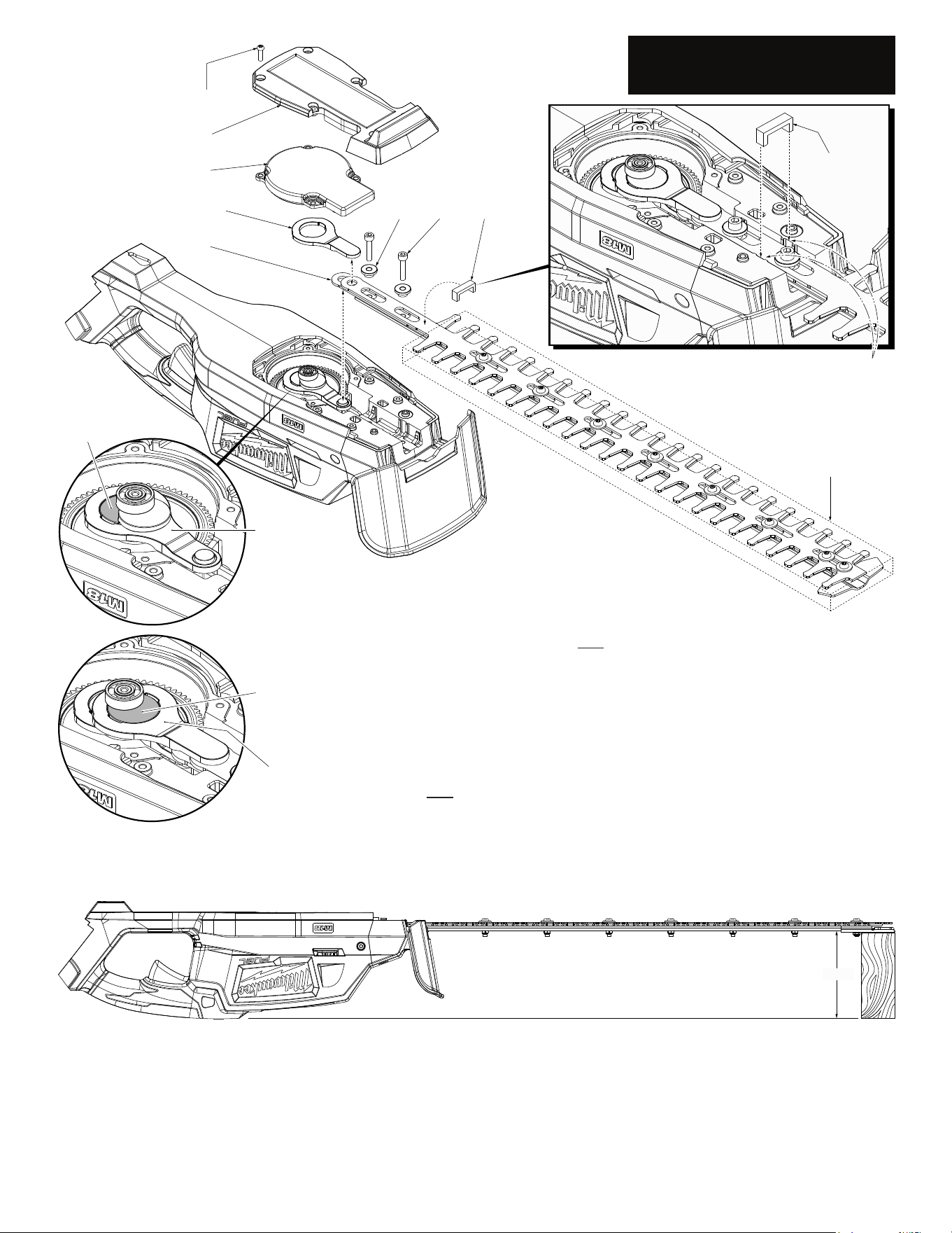
3.50”
NOTE:
The service
replacement blade
assembly (1) is shipped
in a clear poly sleeve and
cardboard. It is recommended
to keep the cutting blade portion
of assembly in the poly sleeve/card-
board for safe handling during installation.
Gear case grooves to
capture felt seal
Poly Sleeve/Cardboard
Eccentric
Surface ‘A’
Connecting
Plate (12a)
Eccentric
Surface ‘B’
Connecting
Plate (12b)
7(6x)
6
8
12b
1
2(2x) 3(2x) 38
Felt
Seal (38)
Support the tool body so the bottom of
the tool is parallel with the work surface
INSTALLING REPLACEMENT BLADE ASSEMBLY (Model 2726-20 Shown)
• Remove battery pack
• Be sure top of Connecting Plate (12a) is ush with surface 'A' of the eccentric on the Gear/
Crank Shaft Assembly (43).
• Install new Blade Assembly (1) onto connecting plate (12a) as shown by placing the hole of the
blade assembly over the lug on the connecting plate.
• As an aid to keeping the connecting plate (12a) ush to the 'A' surface of the eccentric,
support the tool housing on one end being sure the bottom of the gear case is parallel with the
work surface. Place a 3-1/2" wood block on the other end under the tip of the replacement blade
assembly, see illustration below.
• Place Connecting Plate (12b) over the bearing and onto the eccentric of the Gear/Crank Shaft
Assembly (43). Place the lug of connecting plate (12b) into the hole of the blade assembly.
NOTE: An instrument such as a nail or small screwdriver may have to be inserted into the exhaust
vent to rotate the fan so the eccentric can turn and line up the hole with the lug. Be sure eccentric
surface 'B' is ush with the top surface of connecting plate (12b).
• Place Felt Seal (38) over the blade assembly. Tuck each end down into grooves on gear case.
• Place a light coating of lubrication onto the Bushings (2) and place onto slots of blade assembly.
• Place a drop of red locking sealant onto the threads of screws (3). Insert screws through the bush-
ings and secure to the gear case.
• Place Gear Cover (8) onto gear case.
• Place Gear Case Cover (6) over gear cover and onto the gear case. Secure with six screws (7).
• Remove plastic cover (if used) from blade assembly. Install battery and check for functionality.
ALWAYS REMOVE BATTERY PACK
BEFORE PERFORMING ANY
MAINTENANCE OR REPAIRS
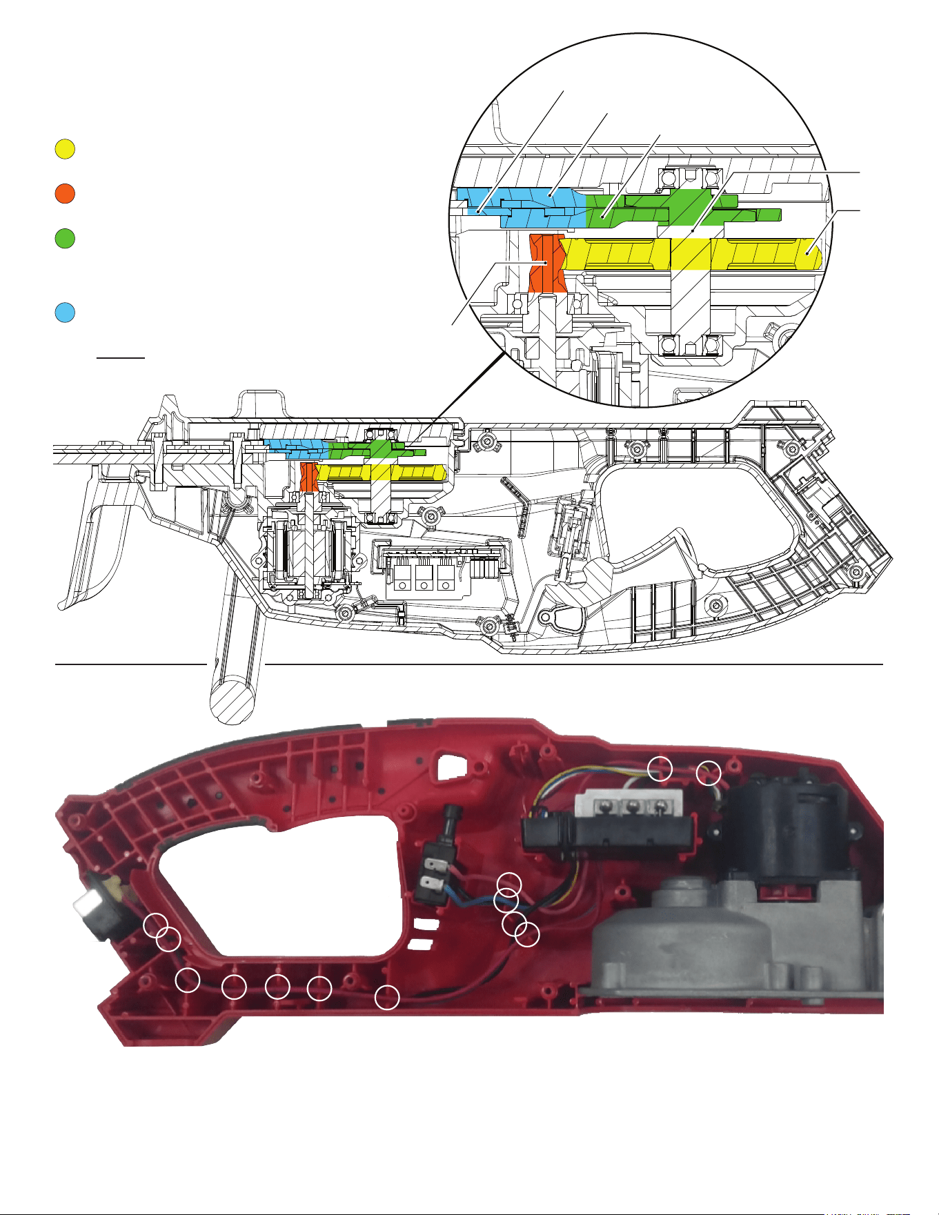
LUBRICATION
White Lithium Grease
NOTE:
When servicing the tool, 90-95% of the old grease must be
removed prior to new grease being added.
Apply a heavy coat of grease around the perimeter of the
gear, being sure to cover all gear teeth (approx. 3 grams).
Apply a heavy coat of grease to the motor pinion, being
sure to cover all the pinion teeth (approximately 3 grams).
Apply a thick film of grease to the entire connecting rod,
including the walls of the ID, (2 pieces).
Apply a thick coat of grease to the corresponding contact
area of the crank shaft (approximately 2 grams).
Apply a thick coat of grease to the blade assembly where
there is contact with the connecting rods (approx. 2 grams).
NOTE: DO NOT over lubricate tool! Too much grease can
cause grease discharge through the gear case.
Gear
Pinion
Upper Connecting Rod
Lower Connecting Rod
Blade Assembly
Crank
Shaft
• Attach the Motor Insulator Assembly, containing the Stator (26d), to the Gear Case /Rotor Assembly (45).
PlacethatassemblyrmlyandsquarelyintheHousingSupport(33).
• PlacethePCBA(26c),Switch(26b)andBatteryConnectorBlockAssembly(26a)rmlyandsquarelyinthe
corresponding cavities in the Housing Support (33).
• Routethewiresasshown,beingsuretopushthewiresrmlydownintothetraps(markedwithwhitecircles).
• ReturnSwitchTrigger(31),Lock-OButton(30)andSpring(28)totheproperlocationintheHousingSupport.
• Carefully install the Hand Guard (44) and Housing Cover (32) onto the Housing Support, checking for interferences.
• Secure the Housing Halves and Hand Guard with eight Screws (34) and two Screws (29).
• CheckforthethefreemovementandproperfunctionalityoftheSwitchandLock-OButton.
• Install battery and check for proper operation of the entire tool.
WIRING INSTRUCTION