
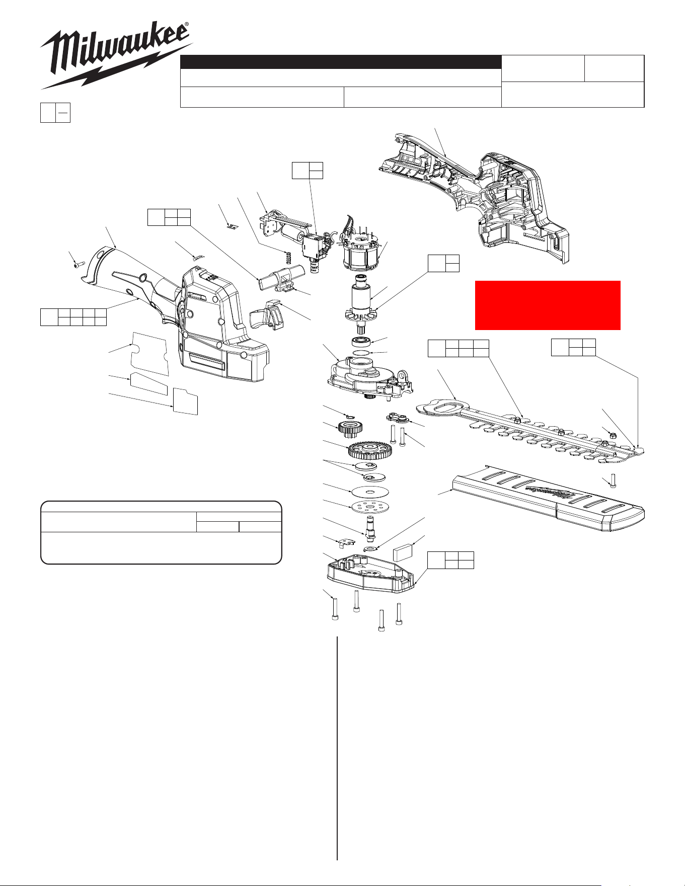
M12™ FUEL™ HEDGE TRIMMER
2533-20
M68A
54-49-2530
See Page 3
Feb. 2022
REVISED BULLETIN
SERVICE PARTS LIST
BULLETIN NO.
WIRING INSTRUCTION
DATE
SPECIFY CATALOG NO. AND SERIAL NO. WHEN ORDERING PARTS
CATALOG NO.
STARTING
SERIAL NO.
EXAMPLE:
Component Parts (Small #)
Are Included When Ordering
The Assembly (Large #).
0
00
FIG. PART NO. DESCRIPTION OF PART NO. REQ.
1 --------------- Handle Cover 1
2 40-50-1760 Spring 1
3 --------------- LockoLever 1
4 --------------- Trigger 1
5 42-70-0058 Housing Connection Clip 1
6 --------------- Handle Support 1
7 05-74-0445 M4 x 0.7 Hex Screw 4
8 --------------- Cover 1
9 --------------- Washer 1
10 --------------- Foam Insert 1
11 05-74-0012 M4 x 0.7 Pan Hd. T-20 Screw 2
12 42-40-2533 Cover w/ Bushings 1
13 --------------- Trimmer Blades 1
14 31-55-0455 Blade Sheath 1
16 --------------- Ball Bearing 1
17 --------------- Rotor 1
19 --------------- Ball Bearing 1
20 --------------- Gear Box 1
21 --------------- Washer 2
22 --------------- Output Gear 1
23 --------------- Washer to Middle Shaft 1
24 --------------- 1st and 2nd Driven Gear 1
25 --------------- Cam Coin 2
26 --------------- Cam Washer 1
27 --------------- Cam Cover 1
MILWAUKEE TOOL
l
www.milwaukeetool.com
13135W.LisbonRoad,Brookeld,WI53005
Drwg. 3
32
x12
1
5
46
2
33
29
17
19
45
47
48
49
13
12
11
x2
14
21
10
3
4
20
23
24
22
25
x2
26
27
28
9
8
7
x4
39
40
41
6
35
2 3
4
37
13 22 25
26 27 28
36
29
33
38
8 9
10 21
34
1 6 32 39
40 41 42 46
44
17
19
43
47 48
49 50
FIG. PART NO. DESCRIPTION OF PART NO. REQ.
28 --------------- Output Shaft 1
29 --------------- Stator 1
32 06-82-1080 M3 ST Screw 12
33 --------------- PCBA 1
34 31-44-2533 Handle Housing Kit 1
35 14-46-0493 Trigger Kit 1
36 14-20-0138 PCBA w/ Motor Assembly 1
37 42-26-0018 Trimmer Blade Assembly 1
38 14-30-0046 Gearcase Kit 1
39 10-20-3937 Warning Label 1
40 10-20-3938 Warning Label 1
41 12-20-1033 Service Nameplate 1
42 10-20-3939 Warning Label (Not Shown) 1
43 14-46-0494 Trimmer Blade Hardware Kit 1
44 16-01-2533 Rotor Assembly 1
45 34-40-0108 O-Ring 1
46 10-20-4359 Gauge Label 1
47 --------------- Tip Guard 1
48 --------------- M4 Hex Nut 4
49 --------------- M4 Screw 4
50 --------------- Bushing (Not Shown) 4
SCREW TORQUE SPECIFICATIONS
SEAT TORQUE
FIG. PART NO. WHERE USED (KG/CM) (IN/LBS)
7 05-74-0445 Cover 27-33 23-29
11 05-74-0012 Gear Box 23-27 20-23
32 06-82-1080 Handle Cover 8-12 7-10
Note: When replacing Rotor (17), Note: When replacing Rotor (17),
be sure to replace the O-Ring (45) be sure to replace the O-Ring (45)
because it can damage during because it can damage during
removal.removal.
*
*
7
x4
8
10
11
x2
12
37
28
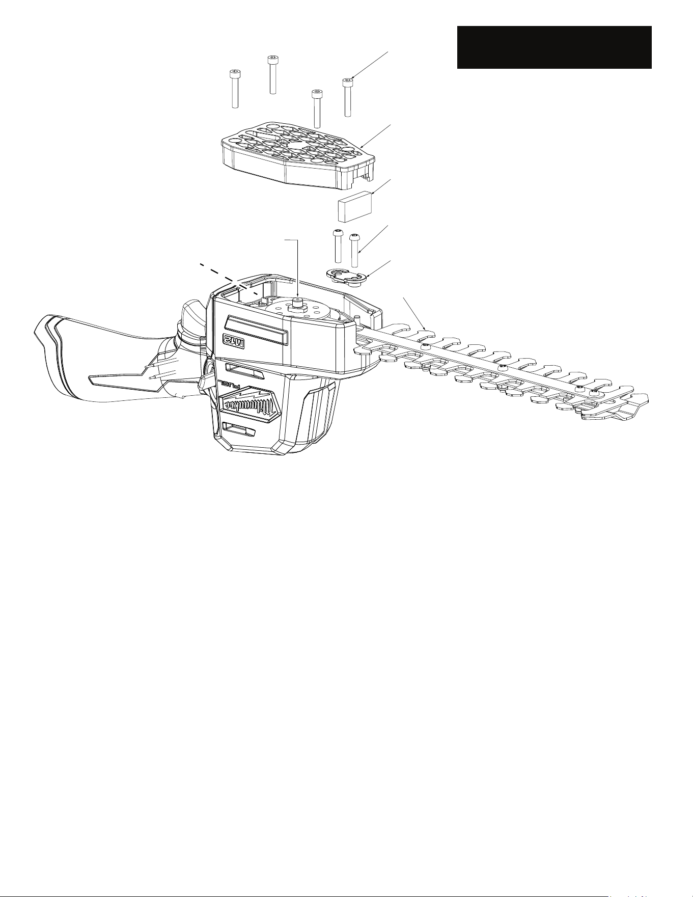
NOTE:
The Trimmer Blade Assembly (37) is
shipped in a clear poly sleeve and
cardboard. It is recommended to keep the
cutting blade portion of assembly in the poly
sleeve / cardboard for safe handling during
installation.
NOTE:
Remove excess debris from Gear Box (20)
cavity when replacing the trimmer Blade
Assembly (37).
REMOVING TRIMMER BLADE ASSEMBLY
• Remove battery pack
• Remove four Screws (7).
• Remove Gearcase Kit (38).
• Remove two Screws (11).
• Remove Cover w/ Bushings (12).
• Remove Trimmer Blade Assembly (37) away from tool.
INSTALLING REPLACEMENT BLADE ASSEMBLY
• Place Trimmer Blade Assembly (37) into gearbox (20) gear side down.
• Place a light coating of lubrication on the Output Shaft (28).
• Place Cover w/ Bushings (12) onto Trimmer Blade Assembly (37)
• Place a drop of red locking sealant onto the threads of screws (11). Insert screws through the Cover w/ Bushings (12) and fasten to Gearbox.
• Place Cover (8) onto gear case.
• Secure Gear Case Kit (38) to Gear Box and fasten four Screws (7).
• Remove plastic cover (if used) from blade assembly. Install battery and check for functionality.
ALWAYS REMOVE BATTERY PACK
BEFORE PERFORMING ANY
MAINTENANCE OR REPAIRS
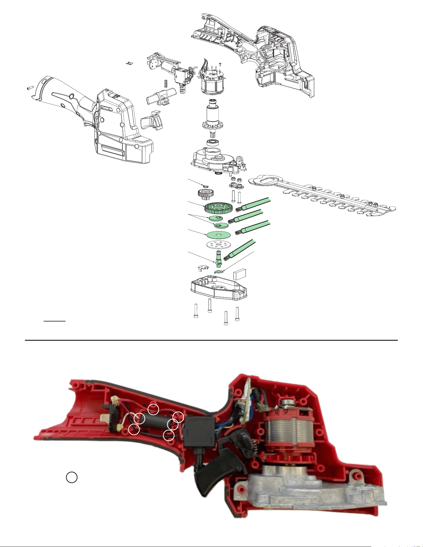
LUBRICATION
Type “J” Grease 49-08-4220
NOTE:
When servicing the tool, 90-95% of the old grease must be
removed prior to new grease being added.
•Apply 0.5g to Washer (21,23) surface.
•Apply 0.5g to Bushing surface inside Cover (8).
•Apply 5.0g to Output Gear (22).
•Apply 2.0g to the Cam Coin surface (25).
•Apply 0.5g to Washer surface (26).
•Apply 2.0g to Output Shaft (28).
NOTE: DO NOT over lubricate tool! Too much grease can
cause grease discharge through the gear case.
21
23
22
25
x2
26
28
Wire traps or Channels
WIRING INSTRUCTION