PRODUCT DATA
68-0222-5
The Honeywell Trademark is used under license from Honeywell
International Inc. by Air-Pure Systems.
Honeywell International Inc. makes no representations or warranties
with respect to this product,
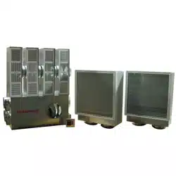
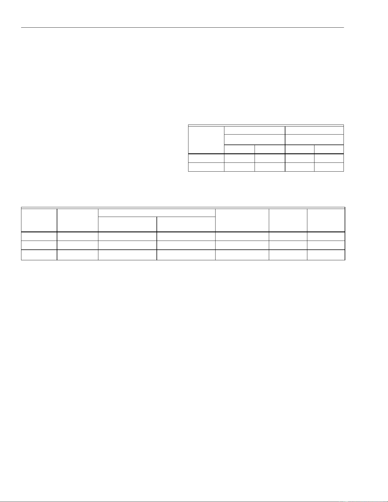
F120 Room Air Cleaning System
GENERAL
The F120 Room Air Cleaning System is designed to collect
particles by circulating room air through a media filter. When
equipped with an optional CPZ module, the system also
adsorbs gaseous contaminants and odors.
The F120 exhaust feature is used to maintain the space at a
negative pressurization relative to adjacent spaces to prevent
contaminants and odors from moving into nearby areas.
The air supply and return design of the F120 allows air
contaminants to be filtered at the center of the room with the
filtered air returned toward the sides of the room for maximum
room air cleaning.
FEATURES
• Specifically designed for use in offices, hospitals,
medical clinics, childcare centers, schools, conference
rooms, copy centers, laboratories, cafeterias, and
hospitality business.
• Ultra-quiet operation allows the system to be used in
sound sensitive areas such as conference rooms,
offices, classrooms and libraries.
• Modular design of air supply and return allows
maximum flexibility when planning the appropriate air
recirculation pattern to maximize overall system
performance.
• Special return module filter removes both particulates
and gaseous contaminants from the air stream.
• Convenient roomside service for all filters.
• Easy-to-change prefilter extends the media filter life.
• Blower module can be mounted remotely from the
room to further reduce sound levels.
• Two-speed fan motor allows selecting high or low
airflow speeds.
• Optional exhaust feature allows installations to
maintain the space at a negative pressure with respect
to surrounding areas to prevent contaminants and
odors from moving into nearby areas.
• Installation is ideally suited to rooms with either two-
by-four or two-by-two foot drop ceiling panels, but can
be installed in any wall or ceiling that allows ducting
space.
• READ AND SAVE THESE
INSTRUCTIONS
M13442
BLOWER
MODULE
RETURN
MODULE
SUPPLY
MODULE
Contents
General..............................................................................1
Features ............................................................................1
Specifications ....................................................................2
Ordering Information .........................................................2
Planning the Installation ....................................................3
Installation .........................................................................7
Operation...........................................................................11
Maintenance......................................................................11
Parts List ...........................................................................11
Warranty............................................................................16
F120 ROOM AIR CLEANING SYSTEM
68-0222-5 2
ORDERING INFORMATION
If you have additional questions, need further information, or would like to comment on our products or services, please write or
phone:
1. Your local Honeywell Commercial Air Products Distributor.
2. Air-Pure Systems
16873 Fish Point Rd. SE
Prior Lake, MN 55372-1714
Phone: (800) 998-1919
Fax: (800) 221-3248
SPECIFICATIONS
IMPORTANT
The specifications given in this publication do not
include normal manufacturing tolerances. Therefore,
this unit may not exactly match the listed specifica-
tions. This product is tested and calibrated under
closely controlled conditions, and some minor differ-
ences in performance can be expected if those con-
ditions are changed.
Model:
F120
consists of:
— two filtered return modules with a return grille, prefilter,
and
— either a 99.97% HEPA filter or a 95% DOP filter and
CPZ module;
— four air supply modules with supply grilles;
— a blower module with a two-speed blower, four
recirculating air supply openings, four recirculating air
return openings and an optional exhaust opening.
— mounting hardware kit consisting of 12 mounting
brackets; 40 ft (12m) of 12-gauge high-tensile strength
wire; six standard T- bar mounts; duct tape;
— seven duct collar straps.
Color:
Blower Housing: Unpainted galvanized steel.
Return and Supply Grilles: Off-white
Electrical Ratings:
a
Off is “O”.
Air Flow Capacity:
a
With exhaust option installed.
b
Purchase filters separately.
Filters:
HEPA: High efficiency particulate air (HEPA) filter is 99.97 per-
cent efficient for 0.3 micron particulates when measured
with Military Standard 282 DOP test.
DOP: Hospital-grade DOP filter is 95 percent efficient for 0.3
micron particulates when measured with Military Standard
282 DOP test.
CPZ: Sorbent modules contain 11 pounds of sorbent. Adsorbs
higher molecular weight hydrocarbons and oxidizes acid
gases and lower molecular weight hydrocarbons.
Ambient Temperature Rating:
Shipping and Storage: -20°F to +150°F (-29°C to +66°C).
Operating: Ambient temperatures ≥90°F (32°C).
Can tolerate 104°F (40°C) for brief periods.
Sound Output Rating at 3.3 ft (1m):
High Speed: 52 dBA (below ASHRAE noise criteria (NC)
curve specifications for NC45 over speech recognition fre-
quency range of 500 to 2000 Hz).
Low Speed: 45 dBA (below ASHRAE noise criteria (NC) curve
for NC35 over speech recognition frequency range of 500
to 2000 Hz).
120 Vac, 60 Hz 240 Vac, 60 Hz
Fan Speed
a
Fan Speed
a
II (high) I (low) II (high) I (low)
Current (A) 7.0 5.5 3.5 2.8
Power (W) 800 695 800 695
Model Voltage
Efficiency
Gas, VOC, Odor
Control Module (2)
Air Vol cfm
(cu m/hr)
Air
Vol cfm
(cu m/hr)
a
Particulates at 0.3
micron (DOP Test)
VOC/Odors
(First Pass Average)
F120A 1023 120 Vac 60 Hz 95% 85% CPZ 900 (1530) 1050 (1780)
F120A 1031 120 Vac 60 Hz 99.97% — — 900 (1530) 1000
(1700)
F120A 1015 120 Vac 60 Hz
bbb
——
F120 ROOM AIR CLEANING SYSTEM
3 68-0222-5
Installation Weight:
Blower Module: 63 lb (28.6 kg).
Supply Module: (4 required): 8 lb (3.6 kg).
Return Module without filter (2 required): 24 lb (10.9 kg).
95% DOP Filter/CPZ Module (2 required): 21 lb (9.5 kg).
99.97% HEPA Filter (2 required): 10 lb (4.5 kg).
Shipping Weight:
F120 with 95% DOP Filter and CPZ Module: 207 lb (94 kg).
F120 with 99.97% HEPA Filter: 182 lb (83 kg).
F120A1015: 152 lb (69 kg).
F120A1007: 70 lb (32 kg).
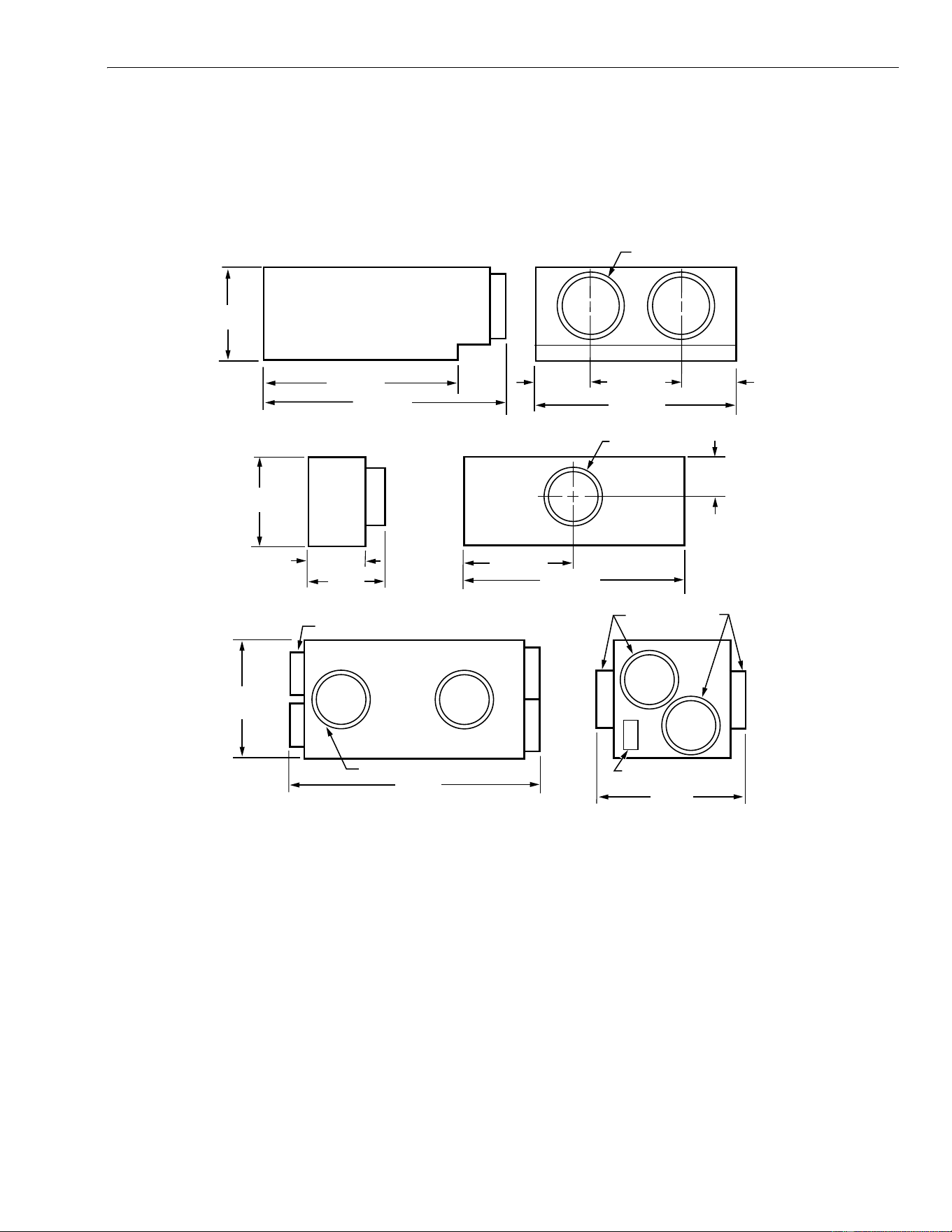
Dimensions:
See Fig. 1.
Fig. 1. Approximate F120 dimensions in in. (mm).
PLANNING THE INSTALLATION
The F120 Room Air Cleaning System is designed for use in
offices, hospitals, medical clinics, childcare centers, schools,
conference rooms, smoking rooms, copy centers, laboratories
and cafeterias.
The quiet design allows the system to be used in sound sensi-
tive areas such as conference rooms, offices, classrooms,
and libraries where other air cleaning systems may be too
noisy.
Determining F120 Size
Use the sizing procedure to determine how many F120 are
needed. The correct number for a particular application
depends on:
• type of contaminant.
• number of occupants.
• room volume.
• room use.
• outdoor air quality.
1. Select the fan speed to be used for the application as
the normal operating speed. Select the speed according
to the sound sensitivity level appropriate for the applica-
tion (if the application requires an especially quiet oper-
ation, low speed sizing is recommended):
a. High speed − the sound output is below the
ASHRAE NC-45 noise criteria curve over the
speech frequency range of 500 to 2000 Hz.
b. Low speed − the sound output is below the
ASHRAE NC-35 curve over the speech frequency
range of 500 to 2000 Hz.
22-3/4 (578)
8 (203) DIAMETER (2)
11
(279)
6-1/2 (165) 6-1/2 (165)
M13406
28-5/8 (727)
23-3/4 (603)
8 (203) RETURN (4)
23-3/4 (603)
9
(229)
34 (864)
20 (508)
16
(406)
11-7/8 (302)
6 (152)
8 (203)
6 (152) DIAMETER
8 (203) EXHAUST (OPTIONAL)
6 (152) SUPPLY (4)
UTILITY BOX AND LOW/
OFF/HIGH (I/O/II) SWITCH
4
(102)
RETURN MODULE
SUPPLY MODULE
BLOWER MODULE

F120 ROOM AIR CLEANING SYSTEM
68-0222-5 4
2. Determine if the room requires optional exhaust feature
to prevent the migration of contaminants to other areas.
(This F120 feature is used to maintain the controlled
space at a slightly negative pressure.)
WARNING
Combustion Hazard.
Installing combustion appliances in same space
as F120 System can cause backdrafting and haz-
ardous gas accumulation.
Consult combustion appliance manufacturer installa-
tion instructions to determine appropriate installation
location.
3. Identify the types of contaminants to be controlled. For
particulates only, use the F120 with a 99.97% HEPA fil-
ter. To remove particulates and control odors and gas-
eous contaminants (for example, smoking rooms), use
the F120 with a 95% DOP filter and a CPZ module.
4. Use the airflow ratings in the Specifications section to
determine the number of F120 needed.
a. Size the air cleaning system using either air
changes per hour (ac/h) or occupant load. See
ASHRAE Standard 62-1999, Ventilation for Accept-
able Indoor Air Quality, for the outdoor air require-
ments. (Use the clean recirculated F120 air for a
portion of the recommended values.)
b. When calculating the system requirements, con-
sider factors such as architectural features, lighting
fixtures, sprinkler systems, HVAC air ducts, and
grilles in the room.
Example 1: Sizing By Occupant Load
A cocktail lounge averages 75 occupants. How many F120
should be installed?
Solution:
F120 required = ASHRAE clean air per person x occupants
F120 airflow capacity
ASHRAE recommends 30 cfm per person clean air for cock-
tail lounges. Operating the F120 on high speed with the
exhaust feature and a 95% DOP filter, the airflow capacity is
1050 cfm. 80 percent of the air is supplied to the space and 20
percent is exhausted. (Air is drawn into the space from sur-
rounding areas to compensate for the air removed.)
Calculation:
Number of F120 required = 30 cfm per person x 75 people
1050 cfm
= 2250 cfm
= 2 units
1050 cfm
Minimal outside air is required.
Outside Air Calculation:
15 cfm per person x 75 people = 1125 cfm.
Example 2: Sizing By Air Changes Per Hour (Ac/h).
A restaurant measures 40 x 45 feet with a 12 foot ceiling. How
many F120 should be installed?
Solution:
F120 feet required = desired air circulation (cfm
)
F120 airflow capacity
Without considering other data, select the correct number of
F120 units that provides between 8 and 12 ac/hr. This
example uses 10 ac/hr. Operate the F120 on high speed with
the exhaust feature and a 95 percent DOP filter; the airflow
capacity is 1050 cfm.
Calculation:
First determine the volume of the space:
Volume = 40 x 45 x 12 = 21,600 cubic feet.
Then determine the volume of air to be circulated.
21,600 cu ft x 10 ac/hr = 216,000 cfh or
216,000 cfh
= 3600 cfm
60 min/hr
F120 required = 3600 cfm = 3 units
1050 cfm
Minimal outside air is required.
Outside Air Calculation:
Provide air equal to 15 cfm/person.
Example 3: Designated Smoking Room
In buildings where smoking is banned in the general office
area but segregated to an enclosed designated smoking room
with its own ventilation system exhausted to the outside, what
is needed?
Solution:
F120 with a 95 percent DOP filter, a CPZ module and the
exhaust feature is the perfect solution for designated smoking
rooms.
The F120 is specifically designed to maintain an acceptable
comfort level for the occupants in rooms with up to fifteen
smokers on High speed and up to twelve smokers on Low
speed.
The exhaust feature exhausts up to 20 percent of the rated
airflow of the F120 and maintains the smoking room at a neg-
ative pressure with respect to the surrounding areas.
Air exhausted from the room is treated by the 95 percent DOP
filter and CPZ module; however, it must be exhausted from
the building and not returned to the HVAC system
Provide minimal outside air. Supply fresh air to the room
through a door grille or an outside duct.
Outside Air Calculation:
Allow 15 cfm per person.
Choosing the Location
The modular design of the F120 allows maximum flexibility to
optimize the airflow pattern when selecting locations for the
blower module, return modules, and supply modules.
1. Plan the position of the return and the supply modules
so the airflow can reach the farthest area of the space:
a. Mount the return modules up to 20 ft (6m) and the
supply modules up to 12 ft (3.5m) from the blower
module (longer duct runs can be used with reduced
airflow).
F120 ROOM AIR CLEANING SYSTEM
5 68-0222-5
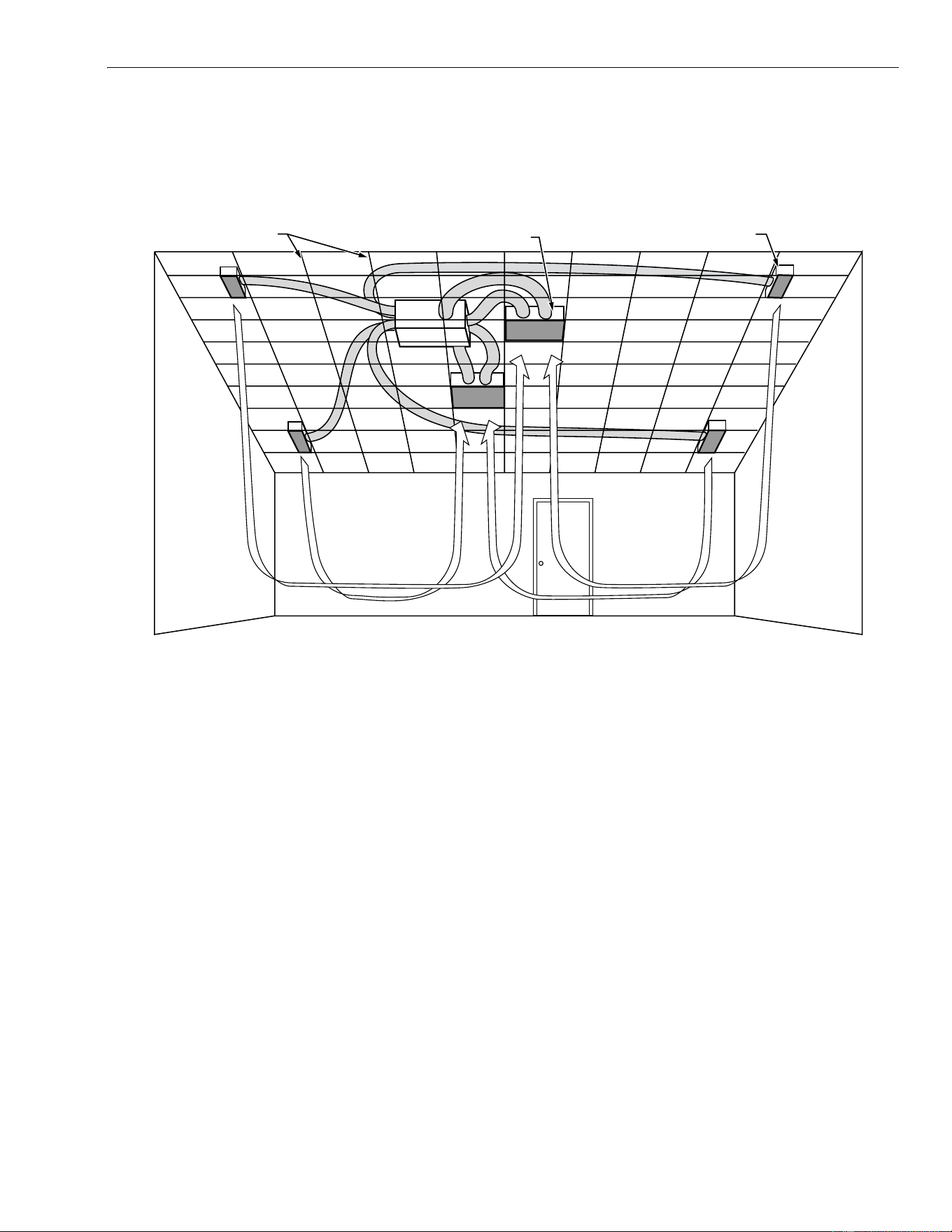
b. Mount the return modules in the center of the area
with two supply modules installed on each side. See
Fig. 2.
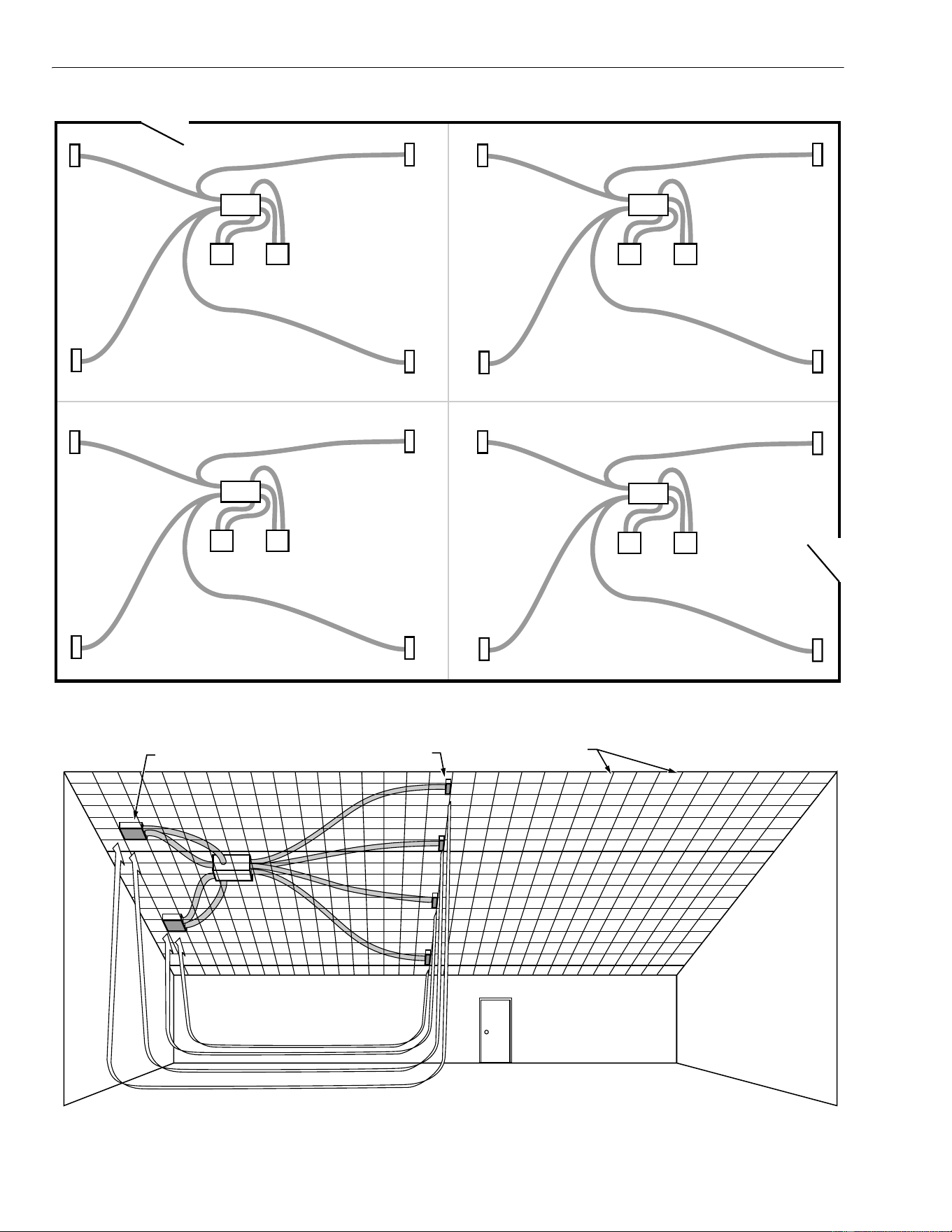
c. With multiple F120 in a room, distribute them
equally throughout the space by dividing the entire
space into equal volumes. See Fig. 3.
d. To use the F120 to divide a large area into smoking
and non-smoking sections, mount the return mod-
ules on one side of the smoking area and place the
supply modules along the dividing line between the
two sections. Use the exhaust option to help keep
the smoke out of the non-smoking section. See
Fig. 4.
Fig. 2. Mounting F120.
AIR SUPPLY
AIR RETURN
CEILING GRID
AIR FLOW AIR FLOW
M13407
F120 ROOM AIR CLEANING SYSTEM
68-0222-5 6
Fig. 3. Installing multiple F120.
Fig. 4. Dividing a large area into smoking and non-smoking sections.
SUPPLY
SUPPLY
SUPPLY
SUPPLY
RETURN RETURN
BLOWER
M13408
SUPPLY
SUPPLY
SUPPLY
SUPPLY
RETURN RETURN
BLOWER
SUPPLY
SUPPLY
SUPPLY
SUPPLY
RETURN RETURN
BLOWER
SUPPLY
SUPPLY
SUPPLY
SUPPLY
RETURN RETURN
BLOWER
AIR SUPPLY
AIR RETURN
CEILING GRID
AIR FLOW
M16629
SMOKING
NON SMOKING

F120 ROOM AIR CLEANING SYSTEM
7 68-0222-5
2. Examine the space above the drop ceiling for
obstructions, such as piping for sprinkler systems,
HVAC ducting or electrical wiring for the lighting system,
that can interfere with installing the F120.
3. Decide where to mount the F120 modules:
a. Hang the blower module from the structural ceiling
above the drop ceiling (minimum of 17 in. is
required).
b. Allow a minimum of 16 in. clearance on all four
sides for the flexible ductwork.
c. For the return and supply modules, allow a
minimum of 12 in. clearance between the drop
ceiling and the structural ceilings, with clearance on
one side for duct access.
4. If the exhaust feature is used with the F120, determine
the location of the exhaust discharge. If the discharge is
more than 50 ft. from the blower module, use an
optional booster blower to achieve adequate exhaust
airflow.
5. For optimum performance of each F120 System:
a. Use the sizing formulas to determine the number of
F120 required for the larger room.
b. Visually divide the entire room into several cubic
volumes. For example, if three F120 are planned,
visualize the room as three roughly equal cubic
volumes.
c. Consider each cubic volume as a single room, and
install the return modules at the center of each area
with the supply modules on the periphery.
d. Draw an installation layout diagram showing the
location of the blower, return and supply modules,
and the exhaust outlet (optional). Use this diagram
later during the air cleaning system installation.
INSTALLATION
WARNING
Explosion Hazard.
Can cause personal injury or equipment damage.
Do not install or use the F120 Room Air Cleaning
System where there is any danger of gas, vapor or
dust explosion.
Do not install when explosion-proof electrical fixtures
are specified.
Canadian Installation: Do not use in ceilings where
fire-resistant assemblies are specified.
WARNING
Fire or Electric Shock Hazard.
Can cause personal injury or equipment damage.
Turn off power source before installing or servicing the
air cleaning system.
When Installing this Product…
1. Read these instructions carefully. Failure to follow them
could damage the product or cause a hazardous
condition.
2. Check the ratings given in the instructions and on the
product to make sure the product is suitable for your
application.
3. The installer must be a trained, experienced service
technician.
4. After installation is complete, check out product
operation as provided in these instructions.
Unpacking Air Cleaning System
CAUTION
Personal Injury Hazard.
Sharp metal edges on components of air cleaning
system can injure hands and fingers.
Wear protective gloves and carefully handle system
components to avoid cuts from sharp metal edges.
Preparing Air Cleaning System for
Installation
1. Unpack, identify and inventory all parts:
• Literature.
• Mounting hardware kit: 12 mounting brackets, 40 ft
(12m) of 12-gauge high tensile strength wire, duct
tape, six 2-ft (0.6) drop-ceiling T-bar mounts.
• Two return modules with grilles.
• Four supply modules with grilles.
• Two high-efficiency filters ⎯ either HEPA or DOP
and CPZ module.
• One package (12) prefilters.
• Blower module.
• Seven duct-collar straps.
• Duct tape.
2. Remove the grilles from the return and supply modules
and set aside until the modules are mounted in the drop
ceiling.
4. Remove all shipping cardboard, plastic and containers
from the system parts.
5. Locate additional items required for the installation (not
included) that the installer provides:
a. External hardware such as extra nuts and bolts
secure the mounting wire or chain to the ceiling.
b. Leveling tool.
c. Drop-ceiling T-bars (4) two-feet (0.6m) long if grids
supplied do not match the grid system.
Preparing Area for Installation
1. Refer to the installation diagram for locations of the
blower, return and supply modules and remove ceiling
panels from those locations.
2. Verify the required clearance between the drop and
structural ceilings:
• blower module clearance of 17 in. (430 mm); 16 in.
(400 mm) clearance is required on all four sides for
ductwork.
• return module clearance of 12 in. (304 mm).
• supply module clearance of 10 in. (205 mm).
• clearance for ductwork.
• 6 in. (150 mm) diameter between blower and supply
modules.
F120 ROOM AIR CLEANING SYSTEM
68-0222-5 8
• 8 in. (200 mm) diameter between blower and return
modules.
• clearance for exhaust duct.
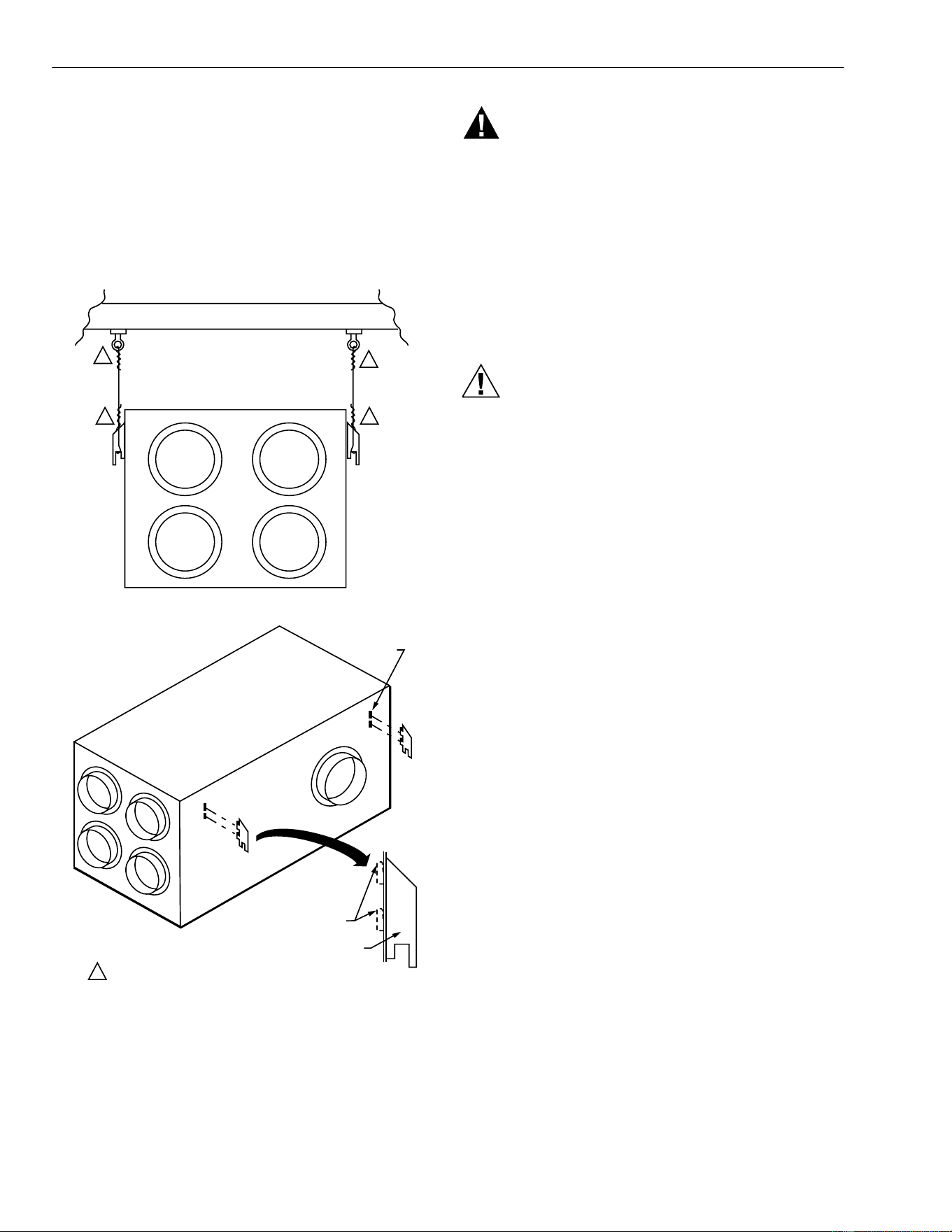
Installing Blower Module
1. Prepare blower module to mount entirely above the
drop ceiling.
2. Mark the location for the mounting bolts in the structural
ceiling. See Fig. 5.
3. Install the mounting bolts in the structural ceiling.
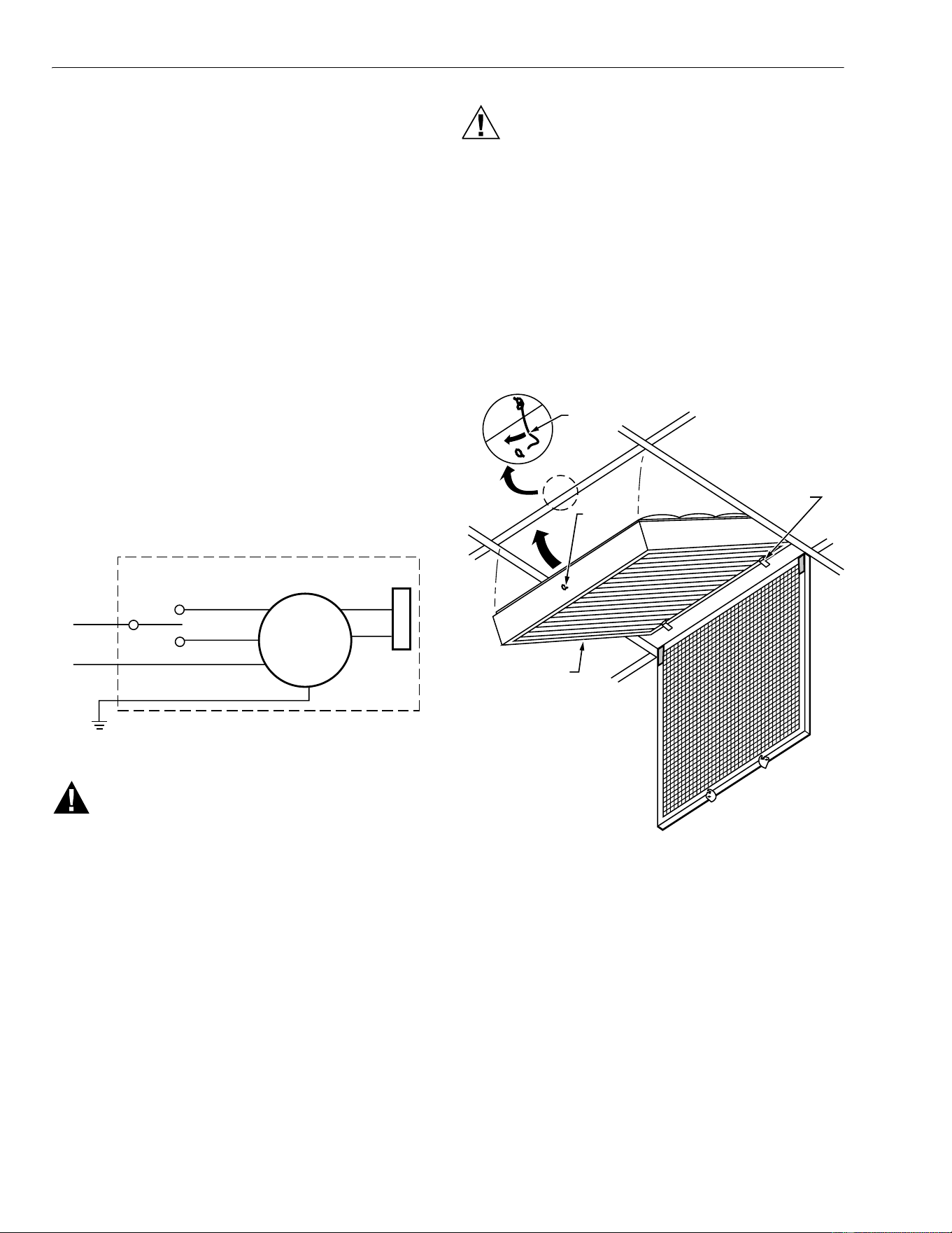
Fig. 5. Installing blower module mounting bolts.
WARNING
Fire and Electric Shock Hazard.
Can cause personal injury or equipment damage.
Wait to connect the power source to the blower
module after securely mounting in the ceiling.
4. Locate the multiple slots on the blower module for
mounting the support shoulder mounting brackets.
See Fig. 5.
5. Insert the brackets into the selected slots.
6. Thread the wire through the brackets. Do not rest the
blower module on the T-bar unless it is reinforced to
hold the weight.
7. Twist the support wire a minimum of four times.
CAUTION
Personal Injury or Equipment Damage Hazard.
Equipment can fall and injure installer or become
structurally weakened, buckled or damaged.
Verify platform is stable and can bear combined weight
of installer and equipment.
Seek installation assistance to prevent return module
from accidentally falling or dropping.
8. Standing on a secure platform, lift the module and raise
it up above the drop ceiling.
9. Attach the free ends of the support wires to the bolts
mounted in the structural ceiling.
10. Check the wire to observe that it supports the blower
module.
11. Level the blower module.
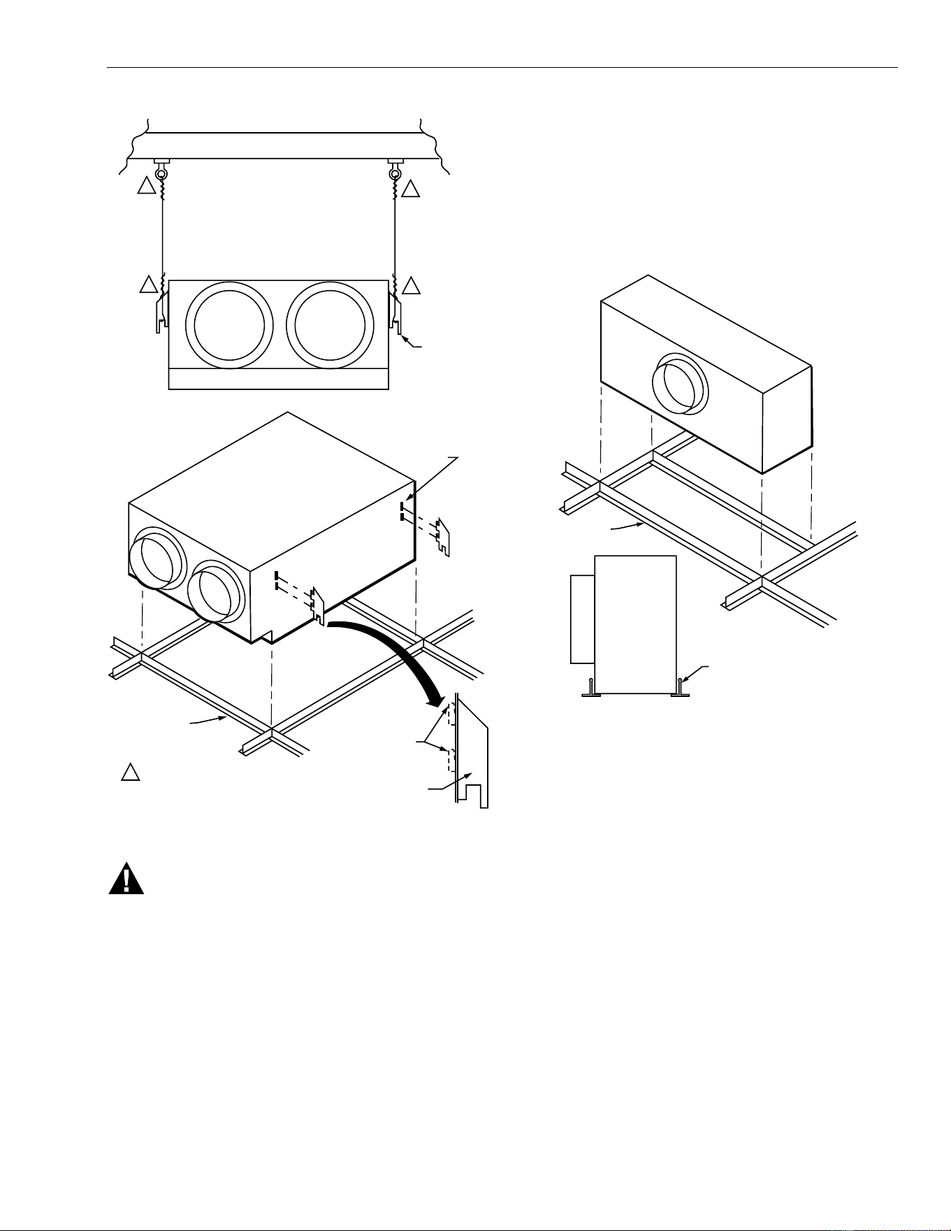
Installing Return Module
1. The return module mounts level with the drop ceiling
T-bars. Mark the location for the mounting bolts in the
structural ceiling. See Fig. 6.
2. Install the mounting bolts in the structural ceiling.
3. Locate the return module slots for mounting the
shoulder support mounting brackets.
4. Insert the brackets into the selected slots.
5. Orient the return module so the duct collars are pointing
correctly.
6. Thread the wire through the support shoulders. Do not
rest the blower module on the T-bar unless it is
reinforced to hold the weight.
7. Twist the support wire a minimum of four times.
F120A
BE SURE TO TWIST THE SUPPORT WIRE A MIINIMUM
OF FOUR TIMES TO PROPERLY HOLD WEIGHT.
SUPPORT
SHOULDER
POSITIONS
M13409
STRUCTURAL CEILING
11
1
1
1
SUPPORT SHOULDER (1 OF 4)
BEND TABS TO
HOLD MOUNT
ON AIR CLEANER
F120 ROOM AIR CLEANING SYSTEM
9 68-0222-5
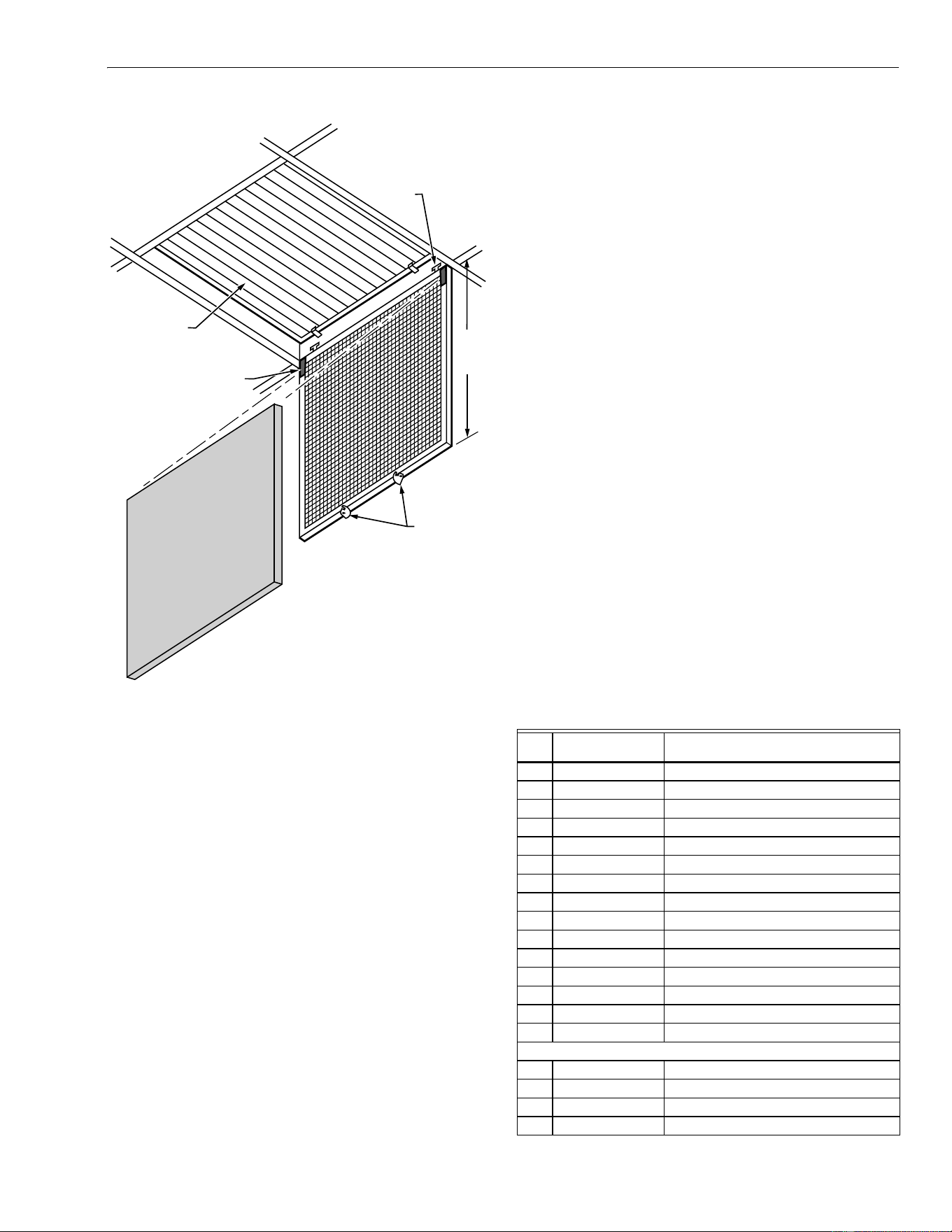
Fig. 6. Installing return module.
WARNING
Personal Injury or Equipment Damage Hazard.
Equipment can fall and injure installer or become
structurally weakened, buckled or damaged.
Verify platform is stable and can bear combined weight
of installer and equipment.
Seek installation assistance to prevent return module
from accidentally falling or dropping.
8. Standing on a secure platform, lift the module and insert
it into the drop ceiling opening level with the T-bars.
9. Attach the free end of the support wire to the bolts
mounted in the structural ceiling.
10. Level the return module.
NOTE: If installed in a 2 x 4-foot ceiling grid, use the
two-foot T-bar provided to trim the return grille.
Resize the drop ceiling panel, if necessary, to
fit.
Installing Supply Module
The supply modules are mounted directly on the drop-ceiling
T-bars. Orient the modules so the duct collars are pointing
correctly for easy duct attachment. See Fig. 7
Fig. 7. Mounting supply modules.
1. Mount the modules directly on the drop ceiling T-bar.
2. Install the two-foot T-bar.
3. Resize the drop ceiling panel to fit.
4. Install the grille by inserting it into the supply module
and letting it rest on the T-bar.
Installing System Ductwork
Select models of the F120 System include 75 feet of 6 in.
diameter flexible ducting to connect the four supply modules
to the blower module. It also includes 75 feet of 8 in. diameter
flexible ducting to connect the two return modules to the
blower module.
1. Measure the 6 in. diameter duct lengths (distance
between blower and supply module 6 in. diameter col-
lars).
2. Cut the ducting to the correct lengths.
3. Install the 6 in. ducting between the blower and the
supply modules.
4. Use duct tape and straps to secure the flexible ducting
to the collars.
5. Measure the 8 in. diameter ducting lengths (distance
between blower and return module 8 in. diameter
collars).
BE SURE TO TWIST THE SUPPORT WIRE A MINIMUM
OF FOUR TIMES TO PROPERLY HOLD WEIGHT.
SUPPORT
SHOULDER
POSITIONS
SUPPORT
SHOULDER
M13410
STRUCTURAL CEILING
1
SUPPORT
SHOULDER
(1 OF 4)
BEND TABS
TO HOLD AIR
CLEANER MOUNT
T-BARS
1
1
1
1
M13411
T-BARS
SUPPLY
MODULE
EDGE OF MODULE RESTS
DIRECTLY ON T-BARS
F120 ROOM AIR CLEANING SYSTEM
68-0222-5 10
6. Cut the ducting to the proper lengths (two 8 in. diameter
ducting are required for each return module).
7. Install the 8 in. ducting to the blower module and to the
return modules.
8. Use duct tape and straps to secure the flexible ducting
to the collars.
9. If using the F120 room exhaust feature, measure the
length from the blower exhaust to the exhaust outlet.
10. Attach the exhaust ducting to the blower exhaust using
duct tape and straps.
Wiring
The F120 has a standard 2 x 4 in. (50 x 100 mm) electrical
box for field wiring. The field-wiring compartment is located on
the return end of the blower module.
IMPORTANT
All wiring must comply with applicable codes and
ordinances. Check that the air cleaner is grounded
for proper operation and safety.
Canadian installation: Do not install in ceilings with
thermal insulation value greater than R-40.
1. Use the appropriate knockout to run the electrical wiring
into the box.
2. Connect the electrical wiring as shown in the Fig. 8.
Fig. 8. F120 wiring diagram.
WARNING
Electric Shock Hazard.
Can cause personal injury or equipment damage.
Be extremely careful to avoid electrical shock during
operation checkout.
Be extremely careful when working near moving parts.
Installing Filters
The F120 offers two types of filters:
1. 99% HEPA.
2. 95 percent DOP with CPZ module.
All filters are installed the same. See Fig. 9.
IMPORTANT
Wear safety goggles when installing or removing the
overhead CPZ™ modules to avoid contact with dust
released during normal handling.
CAUTION
Equipment Damage Hazard.
Can damage filter frame or filter media.
Avoid touching pleated filter media.
Handle only the filter frame.
1. Remove filters from plastic wrapper.
2. Be sure front of filter assembly rests on filter support
hooks in return module.
3. Make sure airflow direction arrow is pointing toward top
of return module and the filter eye hook faces out.
4. Carefully lift the filter and hook frame onto the support
hooks.
5. Swing the filter into the unit and latch the filter frame
securely to the module by inserting the module hook
through the eye bolt on the filter.
Fig. 9. Installing F120 filters.
Installing Grille and Prefilter
When installing, allow space for pulling down the grille a
radius of two feet to open it. Be sure it can open freely without
obstruction.
1. Install the grille by inserting the grille hinge hooks into
the opening in the return module. Be sure the grille
hangs freely from the cabinet. See Fig. 10.
2. Install the prefilter by pressing the filter onto the velcro-
fasteners at the top of the hanging grille. See Fig. 10.
3. Swing the grille up into the cabinet and rotate the two
latches closed.
FACTORY WIRING
BLACK (HI)
RED (LO)
BLACK
WHITE
GREEN
BROWN
BROWN
CAPACITOR
MOTOR
M1340
5
FILTER
SUPPORT
HOOKS (2)
EYE BOLT
FILTER
ASSEMBLY
CABINET
HOOK
M13412
F120 ROOM AIR CLEANING SYSTEM
11 68-0222-5
Fig. 10. Installing grille and prefilter.
OPERATION
The F120 System is engineered to improve indoor air quality
for commercial applications. The filters effectively capture
atmospheric dust, mold spores, smoke, fumes, mists and
aerosols.
Air cleaning systems and ventilators use filtration or dilution to
reduce excessive accumulation of contaminants. To eliminate
airborne contaminants, the source must be removed.
Ventilation standards and codes specify minimum ventilation
rates to dilute air contamination for specific applications. The
rates assume a fresh outdoor air exchange.
Using the F120 to comply with ventilation requirements is an
acceptable alternative to ventilation with outdoor air. It is
recommended that a minimum of 15 cfm per person outdoor
air be provided.
MAINTENANCE
The F120 Room Air Cleaning System is designed with a dual
filter to allow longer intervals between maintenance. Regular
maintenance of the prefilter and filter assembly can be done
easily without special tools:
1. Remove and replace the HEPA filter, which collects
smaller particles not collected by the prefilter. (Washing,
vacuuming and reverse air blasting the filter are not
effective.)The filter lasts 12 to 24 months, depending on
facility occupancy factors.
2. Change the disposable prefilter after every one to two
months of operation.
3. Replace the CPZ Module every four to 24 months,
depending on the application, when the adsorbent emits
a continuously strong pungent odor.
NOTE: When tobacco smoke is the contaminant,
replace both the 95 percent DOP filter and the
CPZ module at the same time.
Replacing the filter
1. Open the two grille latches by swinging down the grille.
2. Remove the dirty prefilter from the velcro holders.
3. Unhook the filter assembly and swing it out of the unit.
4. Lift the filter assembly from the installation hooks and
place it on the floor.
5. Install the filter assembly by positioning it on the installa-
tion hooks with the air flow arrows pointing up to the
unit.
6. Replace the prefilter pad by attaching it to the velcro
holders.
7. Swing the grille into the unit and close the latches.
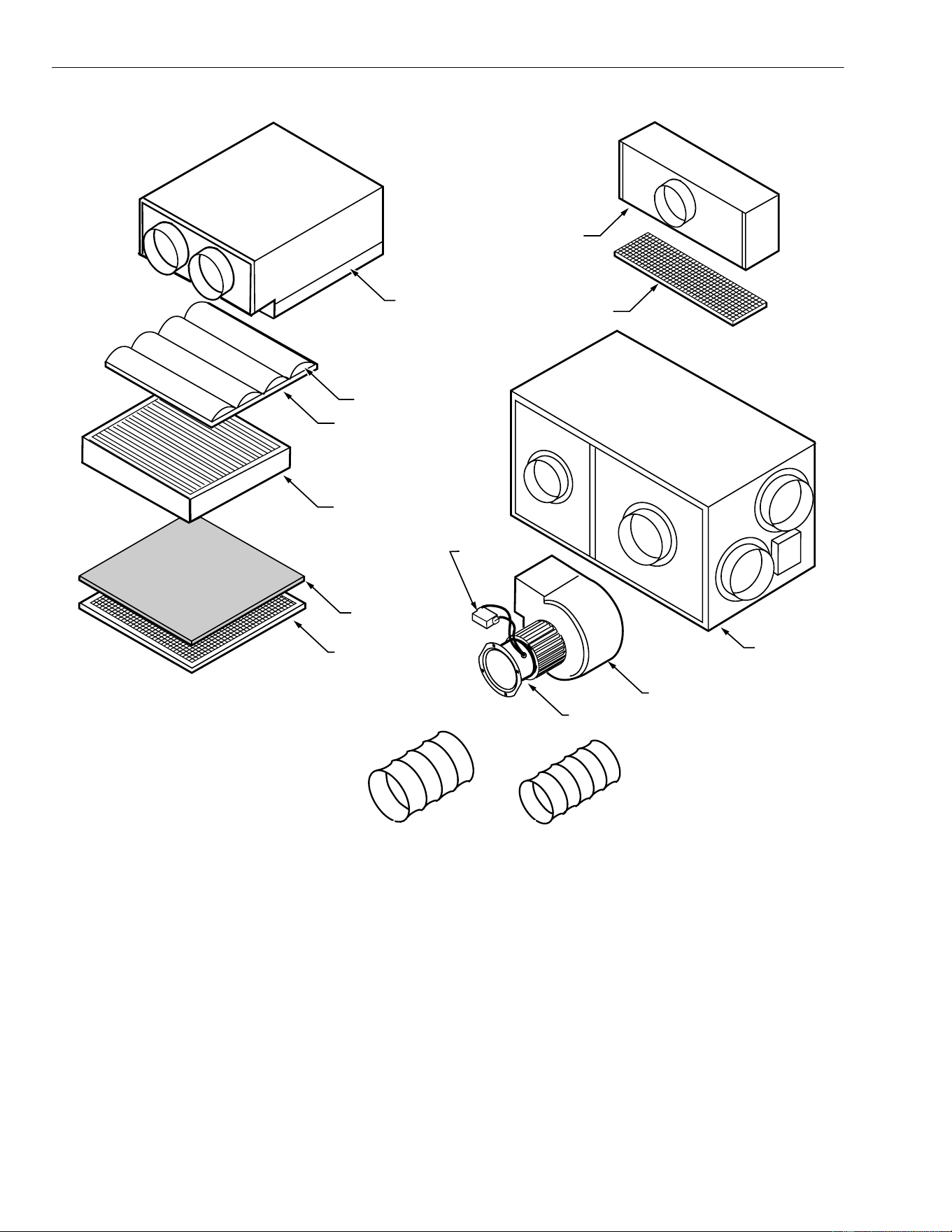
PARTS LIST
See Fig. 11 for exploded view of F120.
FILTER
ASSEMBLY
M13413
PREFILTER
VELCRO
FASTENERS
INSERT GRILL
HINGE INTO
GRILL HINGE
SLOT
GRILLE
GRILLE
LATCHES
2 FT
SWING
RADIU
S
Item
No.
F120A
Part No. Description
1 32003982-001 Return Module (without filters)
2 32003983-001 Prefilter (12 pack)
3 32003984-001 Return Grille Assembly
4 32003985-001 95% DOP Filter
5 32003986-001 99.97% HEPA Filter
6 32003987-001 CPZ Module
7 32003988-001 CPZ Module Frame
8 32003989-001 Blower
9 32003990-001 Motor
10 32003991-001 Blower Module
11 32003992-001 Supply Module with Grille
12 32003993-001 Supply Grille
13
14
15 32003995-001 Motor Capacitor
Parts Not Shown in Fig.11.
32003996-001 Exhaust Kit F120 Upgrade
32003997-001 Filter Exchange Pack
32004137-001 High, Off, Low Switch
32004138-001 Mounting Hardware Kit
F120 ROOM AIR CLEANING SYSTEM
68-0222-5 12
Fig. 11. F120 exploded view.
1. RETURN MODULE
2. PREFILTER
3. RETURN GRILLE
ASSEMBLY
4. 95% DOP FILTER
5. 99.97% HEPA FILTER
6. CPZ MODULE
7. CPZ MODULE FRAME
8. BLOWER
9. MOTOR
10. BLOWER
MODULE
11. SUPPLY
MODULE
12. SUPPLY
GRILLE
15. MOTOR
CAPACITOR
M13414

F120 ROOM AIR CLEANING SYSTEM
13 68-0222-5
NOTES

F120 ROOM AIR CLEANING SYSTEM
68-0222-5 14
NOTES

F120 ROOM AIR CLEANING SYSTEM
15 68-0222-5
NOTES

68-0222-5 Revised 01-09 www.cleanairfacility.com
Air-Pure Systems
16873 Fish Point Rd. SE
Prior Lake, MN 55372-1714
Phone: (800) 998-1919
Fax: (800) 221-3248
F120 ROOM AIR CLEANING SYSTEM
LIMITED TWO-YEAR WARRANTY
Air-Pure Systems warrants its air cleaner products to be free from defects in workmanship or materials under normal use and service, for a period
of two (2) years from the date of purchase by the original end-user. If at anytime during the warranty period the product is defective or malfunc-
tions, Air-Pure Systems, through the distributor or dealer, from which the product was purchased, or through an authorized warranty repair
station, shall at Air-Pure Systems option, replace or repair the defective product or component.
This warranty does not cover removal or installation costs. This warranty shall not apply if it is shown that the defect or malfunction was caused
by damage which occurred during handling or shipment, improper electrical connections, improper use of the product or abuse.
Air-Pure Systems sole responsibility shall be to repair or replace the product within the terms stated above. AIR-PURE SYSTEMS SHALL NOT
BE LIABLE FOR ANY LOSS OR DAMAGE OF ANY KIND, INCLUDING ANY INCIDENTAL OR CONSEQUENTIAL DAMAGES RESULTING,
DIRECTLY OR INDIRECTLY, FROM ANY BREACH OF WARRANTY, EXPRESS OR IMPLIED, OR ANY OTHER FAILURE OF THIS PROD-
UCT. (Some states do not allow the exclusion or limitation of incidental or consequential damages, so this limitation may not apply to you.) THE
WARRANTIES SET FORTH HEREIN ARE EXCLUSIVE AND AIR-PURE SYTEMS EXPRESSLY DISCLAIMS ALL OTHER WARRANTIES,
WHETHER WRITTEN OR ORAL, IMPLIED OR STATUTORY, INCLUDING BUT NOT LIMITED TO ANY WARRANTIES OF MERCHANTABIL-
ITY, WORKMANSHIP, OR FITNESS FOR A PARTICULAR USE.
This warranty gives you specific legal rights and you may have other rights which vary from state to state.
How to make a warranty claim or have questions answered:
Should you have a warranty claim or questions about the warranty policy, contact the distributor or dealer from which you purchased the product
or the authorized warranty repair stations nearest your location.
NOTE: Do not return any products or parts to the factory without a factory issued “Returned Warranty Goods Label” issued by Air-Pure Sys-
tems.
In the event you or other persons, have any questions concerning the use and care of this product or this warranty please call or write the factory.
Air-Pure Systems
16873 Fish Point Rd. SE
Prior Lake, MN 55372-1714
Phone: (800) 998-1919
Fax: (800) 221-3248
