DEUMIDIFICATORI
DEHUMIDIFIERS
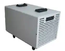
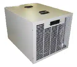
FDKA100.1
MANUALE D’USO E MANUTENZIONE
USE AND MAINTENANCE MANUAL
M.FDKA100.1-03 09/20/18

2
M.FDKA100-03
M.FDKA100.1-03
1. SAFETY WARNINGS
• The FDK100 Series Dehumidifier must always be connected using the grounded electrical
connection as required from all electrical appliances. The warranty is voided and all
responsibility for the operation is born by the owner if non-grounded wiring is utilized.
• The FDK100 Dehumidifiers must only be maintained and serviced by a qualified technician.
• The FDK100 Dehumidifiers are intended only for operation when oriented with the unit sitting on
its feet and level. Any other orientation could cause water to come in contact with the electrical
components. Remove plug before moving dehumidifier. If any water may have spread
throughout unit, the unit should be opened and allowed to dry thoroughly before reconnected to
electric and restarting.
• For proper operation, neither the inlet or discharge should be positioned against a wall. The
inlet requires a minimum of 12” clearance and the discharge needs a minimum of 24” clearance.
• For proper diffusion of air throughout the room, the dehumidifier should be positioned with the
sides against a wall and the inlet and discharge perpendicular to the wall.
• Do not insert any objects into the inlet or discharge. If service is required, call a qualified
technician. All work on unit should be down with the unit “off” and unplugged.
• Do not use water to clean unit exterior. Only use a damp cloth with unit unplugged.
• Do not use unit as shelf or device to hang clothes. This could cause damage to unit.
• The inlet filter generally needs cleaned once per month. Check unit on a weekly basis to ensure
that more frequent cleaning is not required.
Identification:
For future reference, write down the model, serial number, date of purchase and use this information
wh
enever corresponding concerning your dehumidifier.
Model Number ______________________
Serial Number _____________________________
Da
te of Purchase _____________________________
Warning
115 Volts AC may cause serious injury from electric shock.
1. Disconnect electrical power before servicing
2. Plug unit only into grounded electrical outlet
3. Do not use extension cord
4. Do not use plug adapter
Power Supply: 115V, 60 Hz
AC Only 1 Phase
Outlet Requirement: 3-Prong
Circuit Protector: Only compressor thermal and overload relay protector
Circuit Breaker Fuse on PCB supply
3
M.FDKA100-03
M.FDKA100.1-03
2. DESCRIPTION OF THE MACHINE
Functioning
This dehumidifier is a refrigerating cycle dehumidifier: its functioning is based on a physical principle
according to which the air, coming into contact with a cooled surface, wets the surface by covering it
with humidity in the form of condensed drops, or ice with low ambient temperature. What really happens
is that a refrigerating machine maintains in a refrigerated state the coil through which is conveyed the
incoming air that, in this way, is cooled and dehumidified. Then the air, passing through a warm heat-
exchanger, heats up and returns in the room dehumidified and at a slightly higher temperature.
The FDK100 Dehumidifier is a refrigerating machine which utilizes its Electronic Board for Room
Humidity control and Defrosting Device control. When the relative humidity goes above the selected set
point, the dehumidifier will energize. Air, moved by an electric fan, is drawn across an evaporator coil.
The evaporator coil is cooler than the dew point of the air so moisture will condense out of the air.
Air is then reheated through the condenser coil and distributed back into the room at a little bit higher
temperature and lower Relative Humidity.
If the room temperature is lower than about 70°F, the
condensed moisture become ice; In this case
every roughly 30 minutes, a defrost device allows, tanks a Solenoid Valve, hot gas supplied by the
compressor enter the evaporator melting the ice.
3. INSTALLATION
The area to be controlled should be sealed with a vapor barrier. If installed in a crawlspace, all vents
should be sealed.
Place dehumidifier on level surface
CAUTION – Once unit is positioned, if the machine didn’t remain always in vertical position, wait
minimum 5 hours before turning the unit “on.” The Electronic board manages the compressor start and
stop to prevent the compressor starts too close.
Route drain line (3/4” ID tubing) to drain condensed water outside of the area.
Plug unit into 10 amp grounded outlet.
To operate unit, press Power key until unit energizes.
o Co
nfirm compressor is running and allow to run for minimum of 15 minutes
If under 70°F, a layer of ice will form on evaporator coil
If over 70°F, a layer of frost or water droplets will form on coil
After you’ve confirmed satisfactory operation of unit, humidistat should be set at desired position
for automatic operation.
NOTE: Humidistat settings are approximate only. For critical applications, you may want to confirm
actual settings with a psychrometer and adjust according.
4
M.FDKA100-03
M.FDKA100.1-03
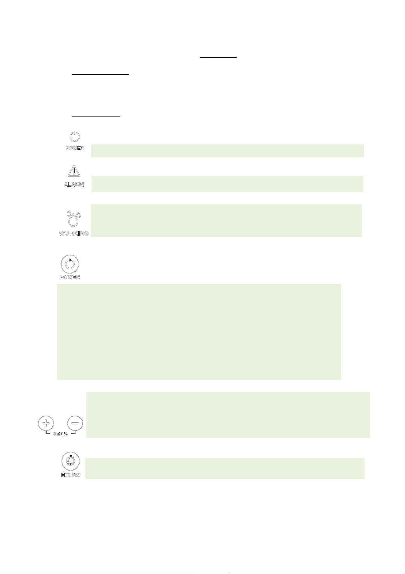
3. CONTROL
Signalling panel
Units are provided with signalling light panel that indicates unit operational status. Below is
reported a brief description of their meaning.
Control panel
The Electronic card with microprocessor, control many functions:
Power LED; it’s on when the machine is in the ON state.
Alarm LED; it’s on when an alarm comes on. It turns off if the alarm is reset.
Working LED
; the LED is on when the compressor is running, blinks when the dehumidifier is
waiting to restart or is in defrost. It’s switched off when, in the ON state, the set of desired
humidity has been reached.
ON/OFF function
; plugged into the outlet (with ground wire!), the display turns on and shows the
relative humidity in the room.
The machine is in the OFF state when the Power LED is off. It’s in the ON state when the Power LED
is on.
When OFF, to switch on the dehumidifier, simply press the POWER key and depending on the
relative humidity set the machine starts working.
When the machine reaches the level of required moisture goes into stand-by mode: automatically
stops but remains in the ON state (POWER LED on).
If the humidity goes above the set point the dehumidifier starts again.
When ON to put the dehumidifier in OFF just press the POWER button (the display continues to
indicate the humidity in the room).
Note: putting the machine OFF and immediately ON, the compressor does not start immediately and
the Run led starts to flash. After a time of 210 seconds the
machine restarts.
HUMIDITY/TEMPERATURE SET function
; press one of the SET-/ +: the display starts flashing to
indicate the humidity set; continuing to press SET-/ + you can bring to the set of required moisture
(from 30% to 80%). After 4 seconds the display stops flashing and the new set of moisture is
detected by the control unit.
It’s possible to make the machine works regardless of the degree of moisture holding SET- until the
message "Cont" appears.
HOUR COUNTER: to show on the display the machine operating time push switch HOURS.
5
M.FDKA100-03
M.FDKA100.1-03
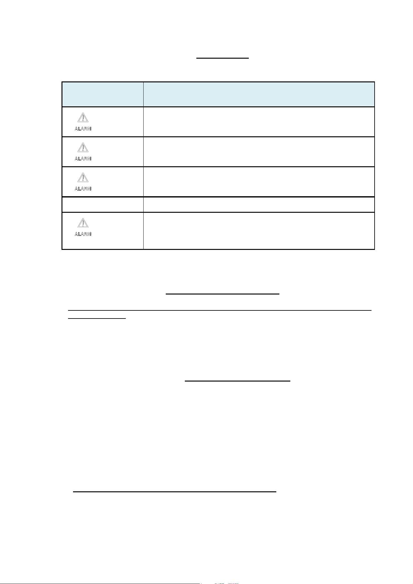
4. UNIT ALARMS
5.
FIRST STARTING OF MACHINE
Before starting the dehumidifier, make sure that the machine has been standing in vertical position
for at-least 5 hours. If one fails to observe this procedure, irreparable damage may be caused to the
compressor. Then one can proceed and connect the dehumidifier plug to a 115 V - one phase
power socket.
If the dehumidifiers is still off, set a lower value of humidity on the control panel .
After about 3 minutes the dehumidifier will start dehumidifying.
6. PERIODICAL MAINTENANCE
Air Filter Cleaning
The only required periodical maintenance is the cleaning of the filter once every month, or more
often if the environment is very dusty or the dehumidifier is working for many hours every day.
The cleaning must be done by placing the filter under a water jet with the drilled panel facing the
floor so that the water jet may push the filter towards the drilled panel.
After a few years running, may be necessary to make a cleaning of the warm heat exchanger
(condenser) by using compressed air. This operation must be done by a specialized technician.
This cleaning will improve the performances and the long life of the machine.
Note: You can require spare filters from your dealer's service.
PROBLEM PROBABLE CAUSE and CORRECTIVE ACTION
+ “Lo t”
It occurs for two possible reasons: the environment temperature is too low or
the defrost cycles are not able to melt the ice in the battery. To reset put the
dehumidifier above 50 ° F, if not reset put the dehumidifier off with POWER
button and unplug the machine.
+ “LoPt”
Possible lack of gas in the circuit. The alarm resets automatically after 210
seconds.
If the alarm does not reset simultaneously press and SET HOURS + for 10
seconds. If the problem occurs again, call for service.
+ “HI t”
Combination of temperature and humidity too high.
The alarm resets automatically when the temperature drops.
“Prob”
Malfunction humidostat. In any case, the machine continues to operate. Contact
the service to replace the humidistat.
+ “Pro1” o
“Pro2” o “Pro3”
Malfunction of one of the three temperature probes. The dehumidifier goes into
stand-by mode. Contact the service to replace the probes.

6
M.FDKA100-03
M.FDKA100.1-03
Warning: Never apply an external source of heat to melt ice off coil.
Maintenance – Annual Inspection of Coils and drain line is required.
1. Unplug Unit
2. Filter may be cleaned by
a. Vacuuming
b. Washing with warm, soapy water. Rinse and shake dry.
3. Coils may be cleaned by
a. Vacuuming the external surfaces of coil
b. Blowing compressed air from behind coils. Hold air nozzle 6” away from coil to avoid
damage.
Warning: Do not steam clean refrigerant coils.
4. Plug in Unit
5. Test Refrigerant Charge
a. Confirm compressor is running and allow to run for minimum of 15 minutes
i. If under 70°F, a layer of ice will form on evaporator coils
ii. If over 70°F, a layer of frost or water droplets will form on coil
6. Test Defrost System
a. Leave unit running for approximately 30 minutes (45-55 minutes). The unit should
enter a defrost mode for approximately 5 minutes. The unit will enter a defrost mode
with the compressor operating and fan off to defrost the coil. If the unit will not defrost,
either
i. Control board may be defective
ii. Bypass valve may be defective
7. After routine maintenance has been completed, return humidistat to desired setting.
If any problems occur during routine maintenance, contact your contractor or the factory.

7
M.FDKA100-03
M.FDKA100.1-03
7. TECHNICAL DATA
Rated Average Power Consumption (at 80°F, 60% R.H.) 960 W
Max. Absorbed Current (at 95°F, 70% R.H.) F.L.A. 13,0 A
Air Flow 600 cfm
Refrigerant R410A
Standard Defrosting Control System electronic
Hot gas defrosting control system termost./ electronic
Condensed Water Draining Pipe Connection 3 / 4 “ M
Functioning Relative Humidity Range (Temperature range 33,8°F-89,6°F) 35 - 99 %
Functioning Relative Humidity Range (Temperature range 89,6°F-96,8°F) 35 - 78 %
Rated Condensation Capacity (at 80°F-60%) 100 ppd
Weight 105 lb
Dimensions LxDxH 20,3 x 25,8 x 20,3 in
Voltage : 115V / 1ph / 60Hz
8
M.FDKA100-03
M.FDKA100.1-03
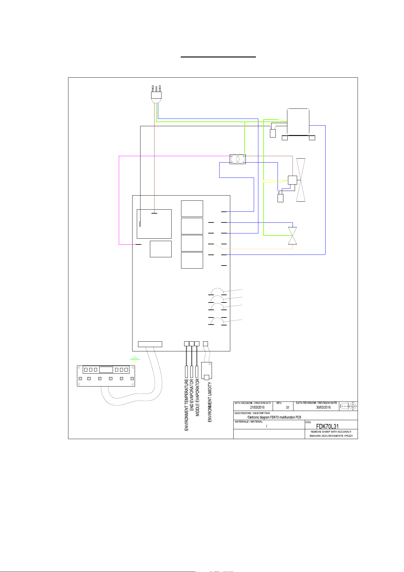
8. ELECTRIC DIAGRAM
COM
F PUMP
FAN
FLOAT
HPS
LPS
COMPRESSOR
P
URPLE
ORANGE
WHITE
BROWN
BLUE
BLUE
FAN
SOLEDOID VALVE
ELECTRICAL BRIDGE 2
ELECTRICAL BRIDGE 3
BLU-BLUE
R.G.A
E.V
PUMP
T1T2
T3
0105
UR
BLUE
POWER SUPPLY
115V-60HZ
PCB 115V-60HZ
TRANSFORMER
115V-220V-60HZ
3x1,5mm
CAPACITOR
40uF
CAPACITOR
1,5uF
BLUE
BLACK
BROWN
ELECTRICAL BRIDGE 1
ELECTRICAL BRIDGE 5
RC
GA

M.FDKA100-03
M.FDKA100.1-03
LIMITED WARRANTY (FRAL FDK54, FDK70 AND FDK100 MODELS)
Customer should not repackage and ship the Fral FKD 54, FDK70 and/or FDK100 (the “Product”) unit
due to possibility of irreparable damage. For warranty service, please contact Aerus Customer Service
by calling 1-888-764-0693 or via email at suppor[email protected].
WHAT IS COVERED BY THIS WARRANTY
Aerus is pleased to pass through to customers the warranties provided to Aerus by Fral, SRL.
Specifically, the Product is warranted to the Customer, subject to the conditions herein, as follows: (i)
the Product will be free of material defects in workmanship and material, for a period of One (1) year
following the date of initial purchase of such Product by an original customer from an authorized reseller
(“Customer”); and (ii) the Product’s condenser, evaporator, and compressor will be free of material
defects in workmanship or materials for a period of five (5) years following the date of initial purchase of
such Product by a Customer.
LIMITATION OF REMEDIES. CUSTOMER’S SOLE AND EXCLUSIVE REMEDY UNDER THIS
LIMITED WARRANTY AND AERUS’ ENTIRE LIABILITY HEREUNDER, SHALL BE, AT THE SOLE
OPTION OF AERUS, REPLACEMENT OR REPAIR OF SUCH PRODUCT OR ITS COMPONENTS
(“COMPONENTS”) BY AERUS OR AERUS’ AGENTS ONLY. REFRIGERANT, PIPING, SUPPLIES,
TRANSPORTATION COSTS, LABOR COSTS INCURRED IN REPAIR OR REPLACEMENT OF SUCH
COMPONENTS ARE NOT INCLUDED. THIS DISCLAIMER AND EXCLUSION SHALL APPLY EVEN IF
THE EXPRESS WARRANTY AND LIMITED REMEDY SET FORTH HEREIN FAILS OF ITS
ESSENTIAL PURPOSE. CUSTOMER ACKNOWLEDGES THAT NO REPRESENTATIVE OF AERUS
OR OF ITS AFFILIATES OR RESELLERS IS AUTHORIZED TO MAKE ANY REPRESENTATION OR
WARRANTY ON BEHALF OF AERUS OR ANY OF ITS AFFILIATES OR RESELLERS THAT IS NOT
IN THIS WARRANTY.
WARRANTY LIMITATIONS
This warranty is expressly conditioned upon proper installation, operation, cleaning, and maintenance,
all in accordance with the Owner’s Manual. Failure to meet any of these requirements will void this
warranty. Servicing of the Product by parties other than Aerus’ authorized representatives and/or using
parts other than genuine parts will also void this warranty. Not for commercial use. Ordinary wear and
tear shall not be considered a defect in workmanship or material. These warranties do not apply for loss
or damage caused by accident, fire, abuse, misuse, improper installation, leaking, modification,
misapplication, weather, freezing, lack of normal care, failure to follow written instructions or any repairs
other than those provided by our authorized Service Center. This warranty is non-transferable and does
not cover consumable items such as filters.
CUSTOMER RESPONSIBILITIES
As a further condition to obtaining warranty coverage hereunder, the Customer must send a valid
warranty claim to Aerus such that Aerus receives such claim prior to the end of the applicable warranty
period. Aerus shall have no obligation hereunder with respect to any claim received by Aerus after the
expiration of the applicable warranty period. As a further condition to obtaining warranty coverage
hereunder, the Customer must present forms of invoices evidencing proof of purchase of a Product. If
such invoices do not clearly indicate the date of initial purchase by a Customer, the applicable Product’s
date of manufacture will be used instead of the date of initial purchase for the purpose of
calculating the commencement of the applicable warranty period. Warranty service must be performed
by Aerus or a servicer authorized by Aerus. In order to obtain warranty service, the Customer should
call Aerus at1-888-764-0693 or via email at support@aerusonline.com, which will then arrange for
applicable warranty service. Warranty service will be performed during customary, daytime working
hours. If the Product must be shipped for service, Customer shall be solely responsible for properly
packaging the Product, for all freight charges, and for all risk of loss associated with shipment.
HOW TO OBTAIN WARRANTY SERVICE
Customer must contact Aerus Customer Service by calling 1-888-764-0693 or via email at
support@aerusonline.com and provide proof of purchase within the above time periods. We will repair
or replace and return the product, without charge and within a reasonable period of time, subject to the
conditions herein, if our examination shall disclose any part to be defective in workmanship or material.
If we, in our discretion, are unable to repair the product after a reasonable number of attempts, we will
provide either a refund of the purchase price or a replacement unit, at the company’s option. We reserve
the right to inspect and/or require conformation o
f
installation method.
9

10
0
M.FDKA100-03
M.FDKA100.1-03
UNAUTHORIZED CHANNELS
Warranties are voided if a product is purchased through unauthorized channels; this includes websites
that are not authorized to use our trademarked names, images, and logos as well as Internet auction
sites (e.g. eBay and Craigslist). To confirm warranty coverage prior to purchasing a product, contact
Customer Service with the product serial number.
EXCLUSION OF OTHER WARRANTIES & CONDITIONS
EXCEPT AS PROVIDED HEREIN, WE MAKE NO REPRESENTATION OR WARRANTY OF ANY KIND.
ALL OTHER WARRANTIES OF ANY KIND, EXPRESS OR IMPLIED, ARE HEREBY EXPRESSLY
DISCLAIMED, INCLUDING ANY IMPLIED WARRANTY OF MERCHANTABILITY OR FITNESS FOR A
PARTICULAR PURPOSE.
LIMITATION OF LIABILITY FOR SPECIAL, INCIDENTAL, OR CONSEQUENTIAL DAMAGES
WE SHALL NOT IN ANY CASE BE LIABLE FOR SPECIAL, INCIDENTAL, OR CONSEQUENTIAL
DAMAGES ARISING FROM BREACH OF EXPRESSED OR IMPLIED WARRANTIES, CONDITIONS,
GUARANTEES, OR REPRESENTATIONS, BREACH OF CONTRACT, NEGLIGENCE, OR ANY
OTHER LEGAL THEORY. Such excluded damages include, but are not limited to, loss of profits or
revenue, and loss of the use of the products, and any loss caused by leaks or other water damage.
FOR U.S. APPLICATION ONLY
This warranty gives you specific legal rights, and you may also have other rights which vary from state
to state. Some states do not allow limitations on warranties, or on remedies for breach. In such states,
the above limitations may not apply to you.
FOR CANADIAN APPLICATION ONLY
Exclusion of Subsequent Owners: Except as otherwise required by applicable legislation, this warranty
is not transferable. This warranty gives you specific legal rights and you may also have other rights
which vary from province to province. Some provinces and territories do not allow limitations on
warranties, or on remedies for breach. In such provinces or territories, the above limitations may not
apply to you.
If any provision of this warranty or part thereof is held by a court of competent jurisdiction to be invalid,
illegal, or unenforceable, the validity, legality and enforceability of the remaining provisions or parts
thereof will not in any way be affected or impaired within the jurisdiction of that court. This entire
warranty shall continue to be valid, legal, and enforceable in any jurisdiction where a similar
determination has not been made.
This warranty is provided by:
Aerus Health Direct, LLC
300 East Valley Drive
Bristol, VA 24201
SERVICE
Every effort is made to ensure customers receive an up-to-date instruction manual on the use of our
products; however, from time to time, modifications to our products may without notice make the
information contained herein subject to alteration. For the latest information, please visit our website.
M.FDKA100.1-03
M.FDKA100-03
dr
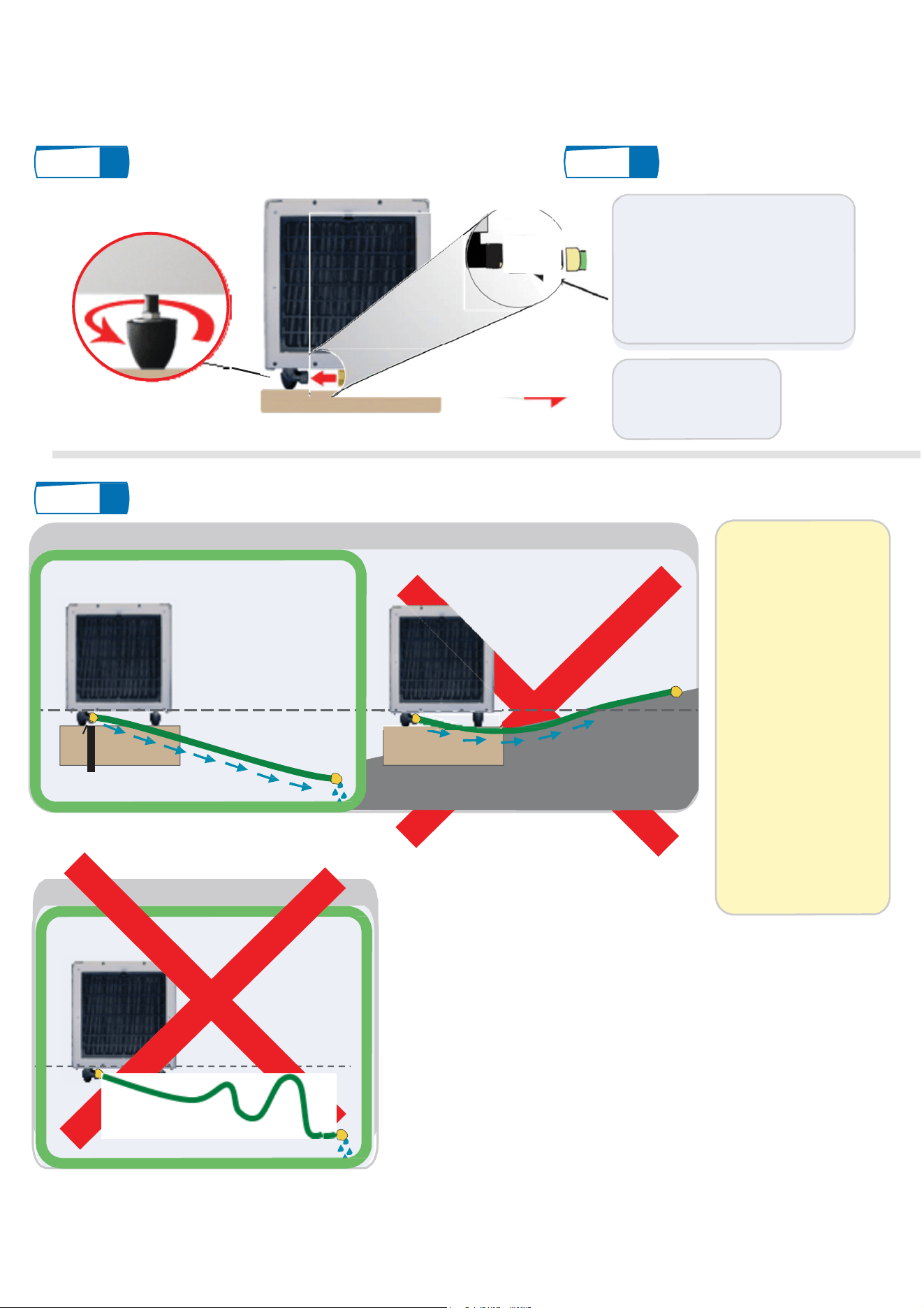
GRAVITY DRAIN INSTALLATION
Step
1 Level Unit
Step
2 Attach Drain Line
Use adjustable
feet to level unit
Screw female end of drain line
onto Fral drain.
The Fral dehumidifier comes
with a fixed drain outlet
underneath the machine, it is a
standard garden hose
thread" (GHT), which is 3/4"
diameter straight
Run line down to drain,
c
ondensate pump or
sump pump.
Note well: If the machine does not have adjustable feet, check that it is properly leveled.
Step
3 Run Drain Line
Option 1: Gravity Drain Installation
NOTICE:
It is very important to
get a constant gravity
flow from the unit to
the condensate pump.
Dehumidifier
Drain Fitting
Level of Dehumidifier Drain Fitting
drain
drain
Make sure no part of
the hose is higher
than the bottom of the
drain fitting.
Note: The drain elbow
is spot welded to the
base of the unit to
allow proper venting
of drain line.
IMPORTANT: The drain hose must run downward and stay below
the level of dehumidifier drain fitting.
Option : Gravity Drain Installation
Level of Dehumidifier Drain Fitting
WARNING: No part of hose can be above level of dehumidifier
drain fitting. Water will not go above this level and will flood the
dehumidifier.
If any water leaks at
this joint, please
check for restrictions
or low spots in drain
line
D
ehumidifier
Drain Fitting
Siphon 1
Siphon 2
ain
W
ARNING: Double siphon is not allowed because it not allow
correct drainage of water
M.FDKA100.1-03
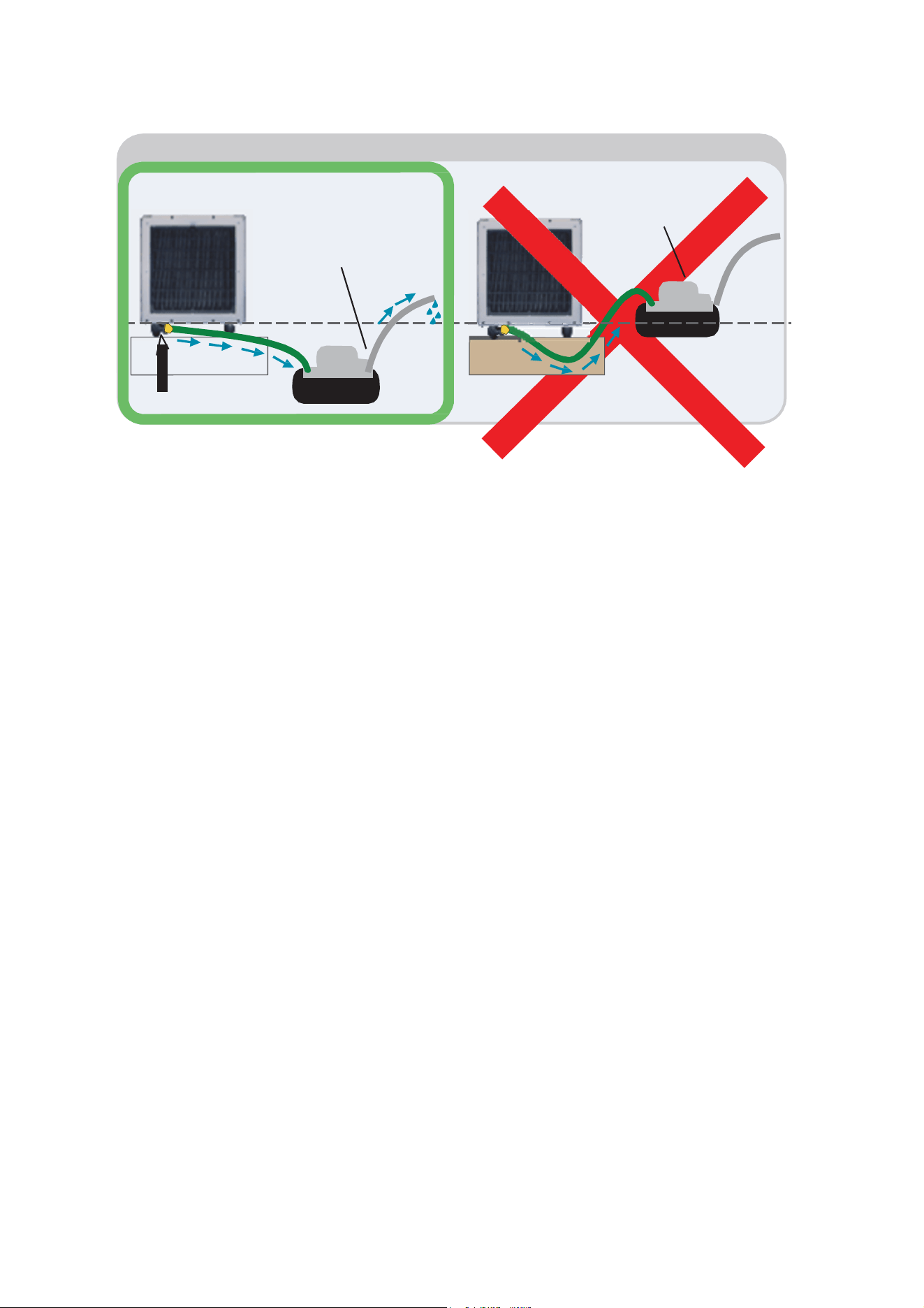
Option 2: Condensate Pump Installation
Condensate
Pump
Condensate
Pump
drain
drain
Level of Dehumidifier Drain Fitting
D
ehumidifier
Drain Fitting
IMPORTANT: The drain hose from
dehumidifier to pump must run downward
and stay below the level of dehumidifier drain
fitting.
Tubing line from pump can run up to 20 feet
upward and out into drain.
WARNING: Hose line going from dehumidifier
into pump must run downward. Water will not
go above the level of dehumidifier drain fitting
and will flood the dehumidifier.