
16
17
20
23
2
8
82
48
10
(4x)
42
(4x)
39
32
43
10
(4x)
33
79
38
(4x)
34
54
56
24
71e
51
(9x)
50
52
15 16 17
19 20 23
70
60
(2x)
55
53
6
9
22
22
72
25
26
24 25
26
73
46
46 47
48
76
33 34 49 50
51 65 66 68
71
40
30
31
30 31
32
74
27
28
29
19
53 54
55 56
80
40 41
42
78
44
45
(4x)
39 43
45
77
15
47
41
4
5
63
7
4 5
7 63
83
11
12
13
14
11 12
13 14
75
1
3
1 2
3
81
22
22
85
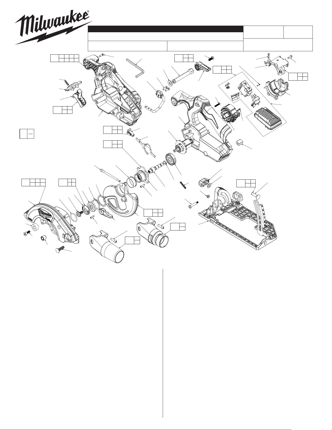
M12 FUEL™ 5-3/8" (136mm) Circular Saw
2521-20 P32A
54-40-2535
See Page Three
FIG. PART NO. DESCRIPTION OF PART NO. REQ.
1 --------------- Flange Bolt 1
2 --------------- 30mm Outer Flange 1
3 --------------- 30mm Inner Flange 1
4 06-82-1087 M3 x 12mm PH T-10 Screw 1
5 --------------- Lower Guard Long Lever 1
6 34-60-0631 Retaining Ring 1
7 --------------- Lower Guard 1
8 40-50-1710 Spring 1
9 45-14-0370 Lower Guard Sleeve 1
10 06-82-5285 6-32 x 1/2 Pan Hd. Taptite T-15 Screw 8
11 --------------- Hub 1
12 --------------- Output Shaft 1
13 34-80-1120 Retaining Ring 1
14 --------------- Output Gear 1
15 --------------- Bushing 1
16 45-04-0485 Bumper Screw 1
17 42-38-0224 Rubber Bumper 1
19 06-10-0455 Carriage Bolt 1
20 --------------- Upper Guard Cover 1
22 05-83-0011 M5 x 17mm Philips Machine Screw 1
23 34-40-5262 O-Ring 1
24 --------------- Spindle Lock Button 1
25 --------------- Spindle Lock Plate 1
26 40-50-1615 Spindle Lock Spring 1
27 06-04-0010 5.5 x 25 Shoulder Bolt 1
28 05-55-0101 M4 Hex Nut w/Nylon Insert 1
29 26-06-0120 Baseplate Assembly 1
30 43-98-0082 Bevel Knob 1
31 45-88-1560 Washer 1
32 06-10-0150 M6 x 25mm Carriage Bolt 1
33 --------------- Handle Support 1
34 44-86-0029 Retention Rubber 1
38 05-83-0012 M3.5 x 19mm Pan Hd. T-15 Screw 4
39 --------------- Stator 1
40 --------------- Motor Housing Support 1
41 --------------- Motor Housing Cover 1
REVISED BULLETIN
SERVICE PARTS LIST
BULLETIN NO.
WIRING INSTRUCTION
DATE
SPECIFY CATALOG NO. AND SERIAL NO. WHEN ORDERING PARTS
CATALOG NO.
STARTING
SERIAL NO.
EXAMPLE:
Component Parts (Small #)
Are Included When Ordering
The Assembly (Large #).
0
00
July 2024
FIG. PART NO. DESCRIPTION OF PART NO. REQ.
42 06-82-1080 M3.0 x 14mm Pan Hd. T-10 ST Screw 4
43 --------------- PCBA 1
44 45-88-0229 M2 x 10mm Pan Hd. T-6 Screw 1
45 05-88-0106 M2 x 5.5mm Pan Hd. T-8 Screw 4
46 --------------- Lockout Switch 1
47 --------------- Trigger 1
48 40-50-1760 Spring 1
49 10-22-0656 Fuel Gauge Label (not shown) 1
50 --------------- Handle Cover 1
51 05-81-5383 M3.5 x 14mm Pan Hd. T-10 Screw 9
52 49-96-0600 3/16" Hex Key 1
53 05-90-0068 Flat Washer 1
54 --------------- Plunge Shaft 1
55 44-10-0645 Depth Lever w/Insert 1
56 05-83-0013 M5 x 12mm Philips Screw 1
60 06-82-0134 M4 x 12.5mm Pan Hd. T-20 Screw 2
63 --------------- Lower Guard Washer 1
65 10-22-0639 Warning Label (not shown) 1
66 10-22-0638 Warning Label (not shown) 1
68 12-20-1014 Service Nameplate (not shown) 1
70 14-30-0255 Gearcase Kit 1
71 14-34-0302 Handles Kit 1
72 14-46-0522 Dust Tube Kit 1
73 14-46-0523 Spindle Lock Kit 1
74 14-46-0521 Bevel Angle Adjust Kit 1
75 14-29-0119 Output Gear Assembly 1
76 14-46-0527 Trigger Kit 1
77 14-20-1012 PCBA & Stator Assembly 1
78 14-38-0098 Motor Mount Housing Kit 1
79 14-46-0547 Rotor Assembly 1
80 14-46-0548 Plunge Lever Kit 1
81 14-46-0549 Blade Retention Kit 1
82 14-36-0346 Rafter Hook Assembly 1
83 14-32-0125 Lower Guard Assembly 1
84 49-22-2530 Rip Fence (Accessory - not shown) 1
85 14-46-0617 DEK26 Dust Tube Kit (Accessory) 1
MILWAUKEE TOOL
l
www.milwaukeetool.com
13135 W. LISBON RD., BROOKFIELD, WI 53005
Drwg. 1
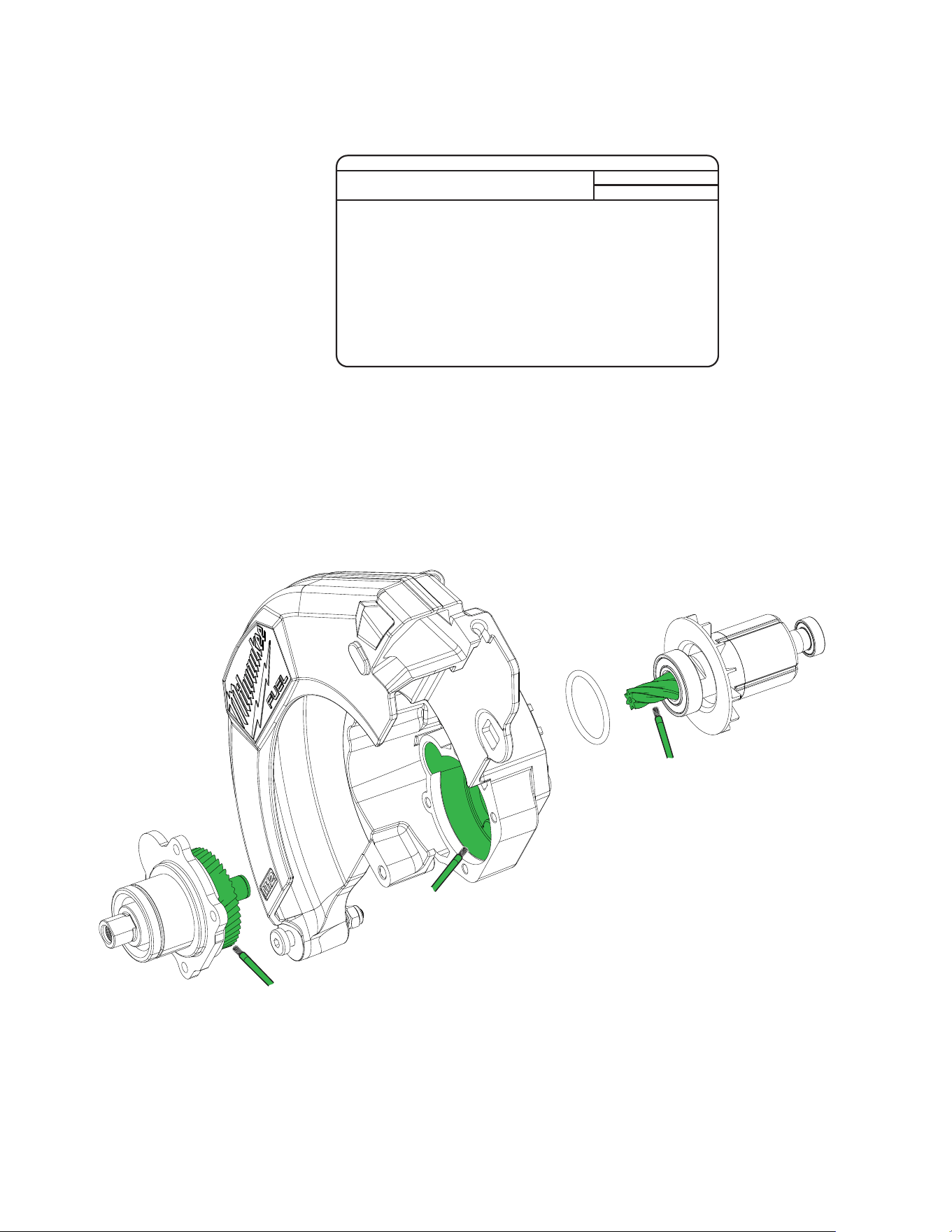
LUBRICATION
Type 'Y' Grease, No. 49-08-5275
Apply 3.0 grams (.10 oz) of 'Y' Grease to the gear bore in Upper Guard Gearcase.
Place a liberal amount of grease on the teeth of the pinion of the Rotor Assembly.
Place a liberal amount of grease on all of the teeth of the output gear In the Spindle
Hub Assembly. Coat the face of output gear and the end of output shaft with grease.
Total amount of grease used is approximately 6.0 grams (.20 oz).
When servicing, remove 90-95% of the existing grease prior to installing Type 'Y'.
Original grease may be similar in color but not compatible with 'Y'.
SCREW TORQUE SPECIFICATIONS
SEAT TORQUE
FIG. PART NO. WHERE USED (kgf-cm) (lb-in)
10 06-82-5285 Hub and Motor Housing 18±2 16±2
16 45-04-0485 Rubber Bumper 35±5 30±4
22 45-04-0485 Vac Port 20±3 17±1
27 06-04-0010 Gearcase 20±3 17±1
38 05-83-0012 Handle Support 10±1 9±1
42 06-82-1080 Motor Housing 10±1 9±1
44 45-88-0229 Worklight 2±0.5 2±0.5
45 05-88-0106 Hall Board 2.7±0.3 2.3±0.3
51 05-81-5383 Handle Cover 10±1 9±1
56 ---------------- Depth Lever 28±2.5 24±2
60 06-82-0134 Rafter Hook 35±5 30±4
1 23 4
5 6
8
7
9
10
11
12
13
14
15
18
17
16
19
20
23
22
21
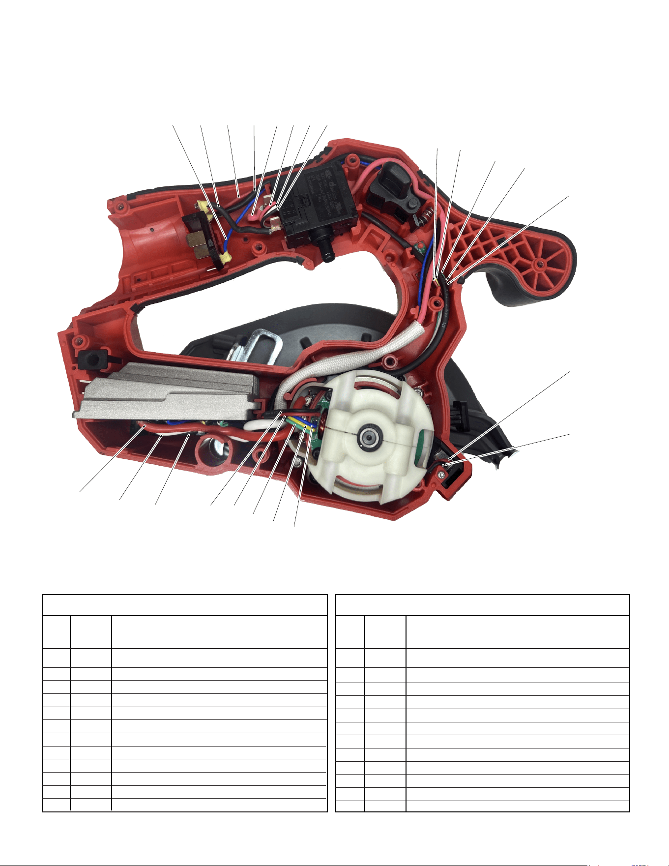
As an aid to reassembly, take notice of wire routing and position
in wire guides and traps while dismantling tool.
Be sure that all components of the electronics kit are seated
rmly and squarely in the housing recesses.
Avoid pinched wires, be sure that all wires and sleeves are pressed
completely down in wire guides and traps.
Prior to securing the housing cover onto the housing support, be
sure that there are no interferences.
Wire
Color
Wire
No.
WIRING SPECIFICATIONS
1 Red From Swich to Control Board
2 Black From Terminal to Control Board
3 Blue From Terminal to Control Board
4 Black From Terminal to Switch
5 Red From Switch to Control Board
6 Black From Switch to Control Board
7 Red From Switch to Control Board
8 White From Switch to Control Board
9 Green From Fuel Gauge Board to Control Board
10 Yellow From Fuel Gauge Board to Control Board
11 White From Fuel Gauge Board to Control Board
12 Black From Fuel Gauge Board to Control Board
Destination
Wire
Color
Wire
No.
WIRING SPECIFICATIONS
Destination
13 Red From Fuel Gauge Board to Control Board
14 Red From LED to Control Board
15 Black From LED to Control Board
16 Black From Control Board to Stator
17 White From Control Board to Stator
18 Red From Control Board to Stator
19 Red From Hall Board to Control Board
20 Black From Hall Board to Control Board
21 Blue From Hall Board to Control Board
22 Yellow From Hall Board to Control Board
23 Green From Hall Board to Control Board