INSTRUCTION MANUAL
PLEASE READ THE INSTRUCTION MANUAL CAREFULLY BEFORE
USING THE UNIT.
www.belling.com.au
www.belling.co.nz
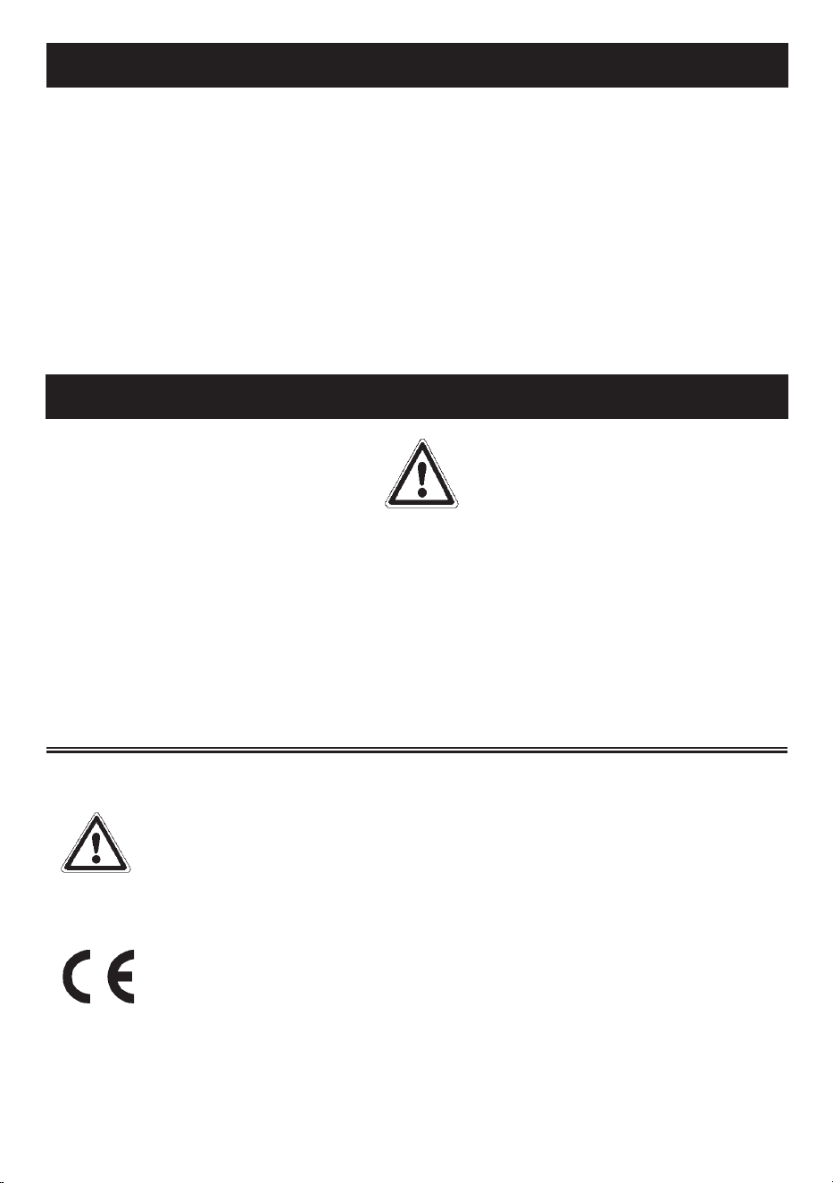
BDO9608BK
90x60cm 8 Function Built-In Oven with LED Program Timer
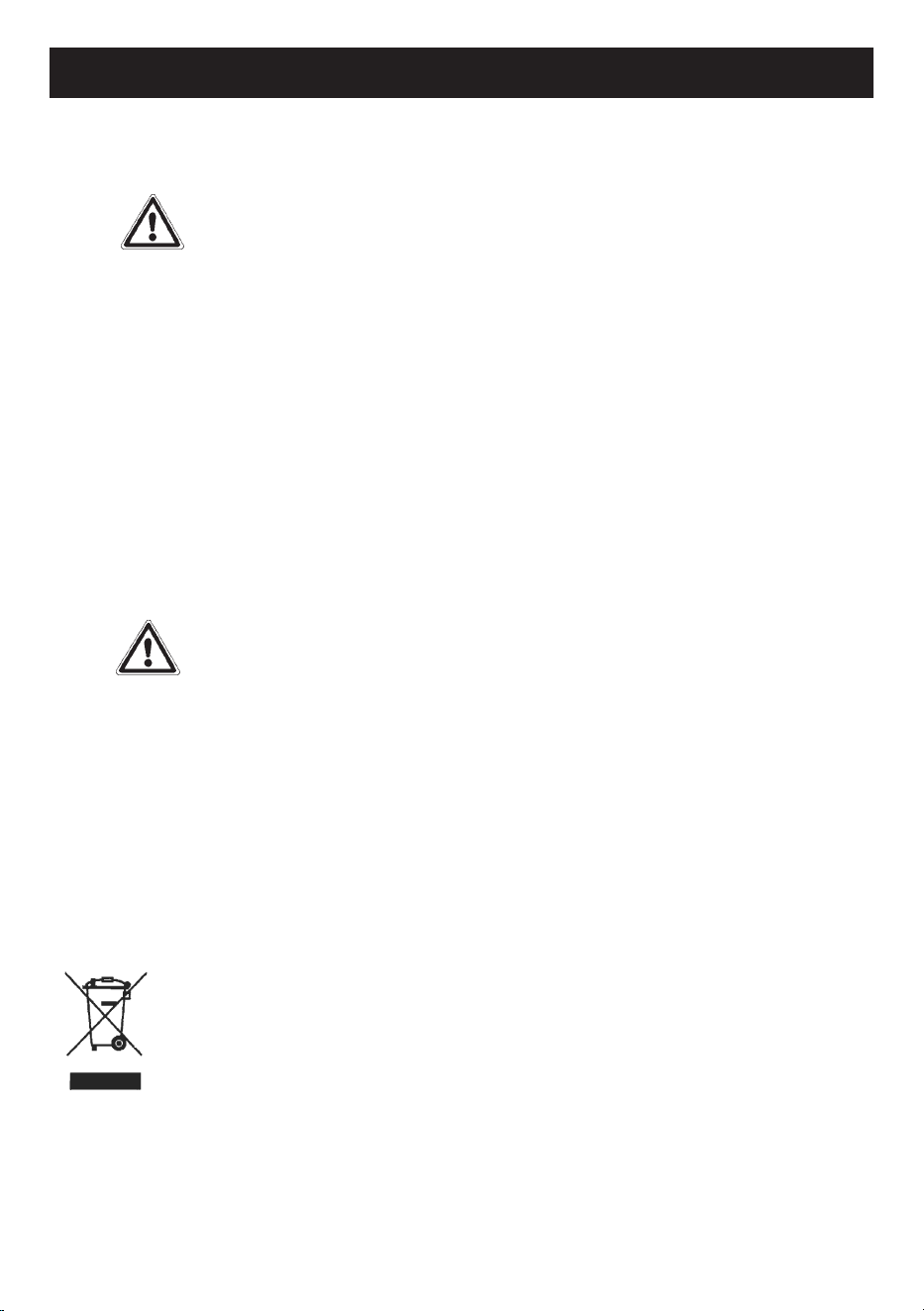
BDO9611BK
90x60cm 11 Function Built-In Oven with Full-Touch LED Display

2
CONTENTS
General Warnings.......................................................................................................3
Disposal.........................................................................................................................6
INSTALLATION
Installation warnings...................................................................................................7
Electrical connection..................................................................................................8
Dimensions...................................................................................................................9
Oven installation.........................................................................................................10
DESCRIPTION
Oven description.....................................................................................................................
12
Accessories...............................................................................................................................
13
First use.....................................................................................................................................
14
8 FUNCTION MODEL
Description.......................................................................................................................15
Cooking functions...........................................................................................................15
Using the timer................................................................................................................17
11 FUNCTION MODEL
Description...................................................................................................................
Cooking functions.......................................................................................................
Operation.....................................................................................................................
Error codes..................................................................................................................
Programmable options..............................................................................................
CLEANING AND MAINTENANCE
Cleaning inside the oven........................................................................................................
Removing the oven door.......................................................................................................
Cooling fan................................................................................................................................32
WARRANTY.............................................................................................................................33
20
21
23
27
28
29
30
3
INTRODUCTION
Dear Customer,
We thank you and congratulate you on your choice to purchase one of
our products. We are confident that this new appliance, built with quality
materials, will fully satisfy your requirements.
Use of this new equipment is easy, however we invite you to read this
manual carefully before installing and using the appliance.
The manual provides correct information on installation, use and
maintenance as well as providing useful advice.
GENERAL WARNINGS
Please read this instruction manual before installing and using the equipment.
The manual must be kept together with the appliance for any future
consultation. If the appliance should be sold or transferred to another person,
ensure that the manual accompanies it, so that the new user will be informed
of the operation and of the relevant warnings.
The product label, with the serial number, is glued to the front of the oven.
All operations relating to installation, adjustment and adaptation
to the power supply available must be carried out by qualified
personnel according to the regulations in force.
The specific instructions are described in the part of the manual
reserved for the installer.
Declaration of Conformity:
we declare that our products comply with the European directives,
orders and regulations as well as with the requirements indicated in the
reference standards.
The manufacturer declines all responsibility in the event of damage to property
or to persons resulting from improper installation or from improper, incorrect or
unreasonable use of the appliance.

4
WARNINGS
Premise
This user manual is an integral part of
the appliance and must be kept intact
and within reach of the user
throughout the life of the appliance.
In case of lost the instruction manual,
it is available in electronic format
upon request from the manifacturer.
Before using the appliance read this user
manual carefully.
Product label
The identification plate shows the
technical data, the serial number and
the power rating.
The identification plate must never be
removed.
Responsibility of the manufacturer
The manufacturer declines all
responsibility for damage to persons
and property caused by:
• Use of the appliance other than that
intended.
• Failure to comply with the
instructions in the user manual .
• Tampering with even a single part of
the appliance .
• The use of non-original spare parts .
Precautions
• WARNING: Ensure that the
appliance is switched off before
replacing the lamp,to avoid the
possibility of electric shock.
• Do not lean or sit on the open door.
• Check that objects are not trapped
in the doors.
Appliance purpose
• This appliance is intended for
the cooking of food in a domestic
environment. Any other use is
improper.
• This appliance is not intended for use
by persons (including children) with
reduced physical, sensory or mental
capabilities, or lack of experience
and knowledge, unless they have
been given supervision or instruction
concerning use of the appliance by a
person responsible for their safety.
• Children should be supervised to
ensure that they do not play with the
appliance.
• The appliance is not designed to
work with external timers or remote
control systems.
• Racks and trays have to be inserted
into the side guides until they come
to a complete stop.The mechanical
safety locks that prevent the rack
from being taken out accidentally
must face downwards and towards
the back of the oven .

5
WARNINGS
Damage to persons
• WARNING:This appliance and its
accessible parts become very hot
during use.
• Do not touch the heating elements
during use.
• Keep children away if they are not
being continuously supervised.
• Children shall not play with the
appliance.
• During use, do not place metal
objects such as knives, forks, spoons
and lids on the appliances.
• Switch off the appliance after use.
• Never try to extinguish a flame/fire
with water: switch off the appliance
and smother the flame with a lid or a
fireproof blanket.
• Cleaning and user maintenance
shall not be made by children without
supervision.
• Have the installation and servicing
performed by qualified personnel in
compliance with the regulations in
force.
• Do not modify the appliance.
• Do not insert sharp metallic objects
(cutlery or utensils) into the slots.
• Never attempt to repair the appliance
yourself or without the intervention of
a qualified technician.
Damage to the appliance
• Do not use harsh abrasive cleaners
or sharp metal scrapers to clean the
oven door glass, since they scratch
the surface, which may result in
shattering of the glass.
• Use wooden or plastic utensils if
necessary.
• Do not sit on the appliance.
• Do not use steam jets to clean the
appliance.
• Do not obstruct the openings,
ventilation and heat dissipation slots.
• Do not leave the appliance
unattended during cooking that can
release fats and oils.
• Do not leave objects on the cooking
surfaces.
• If the door glass breaks, turn off the
oven to avoid electric shock .
• Never use the appliance to heat the
room.
• If the supply cord is damaged, it
must be replaced by the
manufacturer, its service agent or
similarly qualified persons in order to
avoid a hazard.
6
WARNINGS
To dispose of the appliance
• Cut the power supply cable and remove the cable together with the
plug.
Electrical voltage
Danger of
electrocution
• Turn off the power supply from the electrical system.
• Disconnect the power supply cable from the electrical system.
• Take the appliance to the appropriate waste collection centres for electrical
and electronic waste, or return the appliance to the retailer at the time of
purchase of equivalent equipment, on a like-for-like exchange.
• It should be noted that non-polluting and recyclable materials are used for
packaging of the appliance.
• Give the packaging materials to the appropriate recycling centres.
Plastic packaging
Danger of
suffocation
• Do not leave the packaging or parts of it unattended.
• Do not allow children to play with the plastic packaging
bags.
Disposal
By ensuring this product is disposed of correctly, you will help
prevent potential negative consequences for the environment and
human health, which could otherwise be caused by inappropriate
waste handling of this product.
The symbol on the product indicates that this product may not be
treated as household waste. Instead it shall be handed over to the
applicable collection point for the recycling of electrical and
electronic equipment.
Disposal must be carried out in accordance with local
environmental regulations for waste disposal.
For more detailed information about treatment, recovery and
recycling of this product, please contact your local city
council office.

7
INSTALLATION
INSTALLATION WARNINGS
Built-in under worktop
Make sure that cabinet in the rear/bottom areas has
proper opening, of approx 90mm,to allow the oven to
vent properly once fully installed.
Column installation
Make sure that cabinet in the rear/bottom areas has proper opening, of approx 90mm
and 50mm at the top areas,to allow the oven vent properly once fully installed.
• The dimensions and materials of the cabinet in which the built-in oven will be
installed must be correct and must be resistant to temperature increases.
• Please install as shown in figure 3
• Wall panels must be 100°C resistant.
• Plastic panels or adhesives that are not resistant to this heat can deform and sustain
damage.
• The appliance must not be installed behind a decorative door in order to avoid
overheating .
• For safety reasons it is necessary to avoid direct contact with the electrical parts of
the oven.
• The insulation and protection parts must be installed such as to prevent them from
being removed by any instrument.
• The oven must be installed as shown in figure 3 in order to provide a more effective
air flow.
• It is advisable to leave a space of at least 90 mm on the back for the kitchen unit in
which the oven is installed.
• The rear panel of the cabinet unit must be removed to provide better
airflow.
• The rear surface of oven, can be placed against the wall .
• It is not recommended to install the device near refrigerators or freezers, otherwise
their performance may be affected by radiated heat.
• For stationary appliances permanently connected to the fixed wiring, compliance
with this requirement is considered to be met if the instruction concerning
disconnection incorporated in the fixed wiring is in accordance with
AS/NZS 3000.
This requirement is valid only for Australia and New Zealand
Oven technical specification
The oven has been designed to work with single phase 220-240V AC 50/60
electricity.
Carefully read the label of the data plate placed on the oven before installation.
8
INSTALLATION
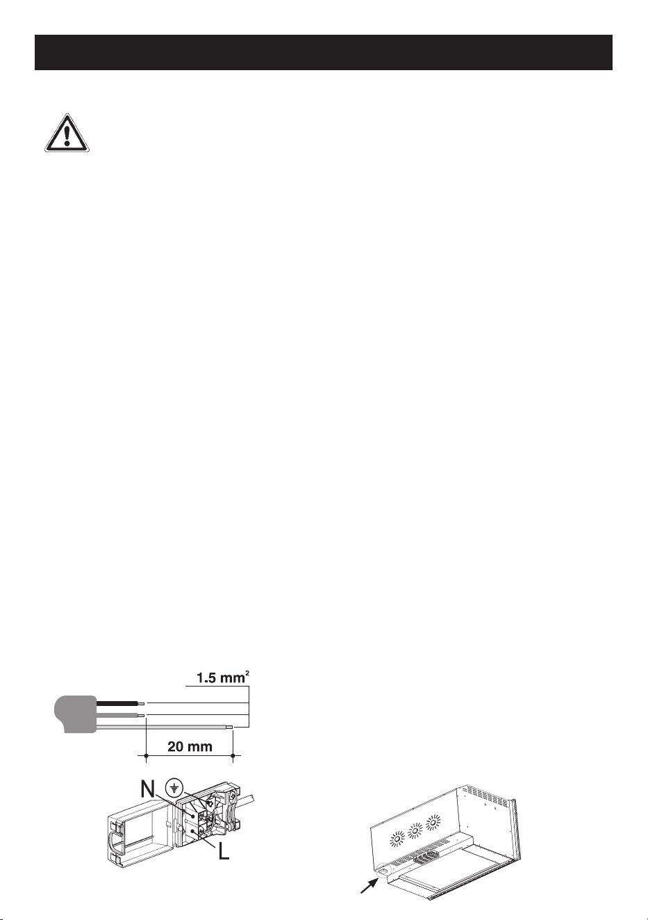
Electrical connection
Danger of electrocution
Electrical voltage
• Have the electrical connection
carried out by qualified technical
personnel.
• The earth connection is obligatory
according to the methods foreseen
by the safety regulations of the
electrical system.
• Turn off the general power supply.
General information
• Check that the characteristics of the
electrical network are suitable for the
data shown on the plate.
• The identification plate, with technical
data, serial number and marking is
visibly positioned on the appliance.
• The plate must never be removed.
• The appliance works with
• Use a three-pole cable (3x1.5mm
2
cable, referring to the internal
conductor section).
• Provide for the earth connection with a
cable longer than the others by at least
20mm.
Fixed connection
If a stationary appliance is not fitted
with a supply cord and plug, or with
other means for disconnection from
the supply mains having a contact
separation in all poles that provide full
disconnection under overvoltage
category III conditions, a means for
disconnection must be incorporated in
the fixed wiring in accordance with the
wiring rules.
The interruption device must be located
in an easily accessible position and
near the appliance.
Connection with plug and socket
Check that the plug and socket are of
the same type.
Avoid using reductions, adapters or
shunts as they could cause heating or
burning.
For the installer
• The plug must remain accessible after
installation. Do not bend or trap the
connection cable to the mains.
• The appliance must be installed
according to the installation
diagrams.
• If the appliance does not function
properly after having carried out all the
checks, refer to Glen Dimplex
customer care
• When the appliance is correctly
installed, please instruct the user on
the correct method of operation.
9
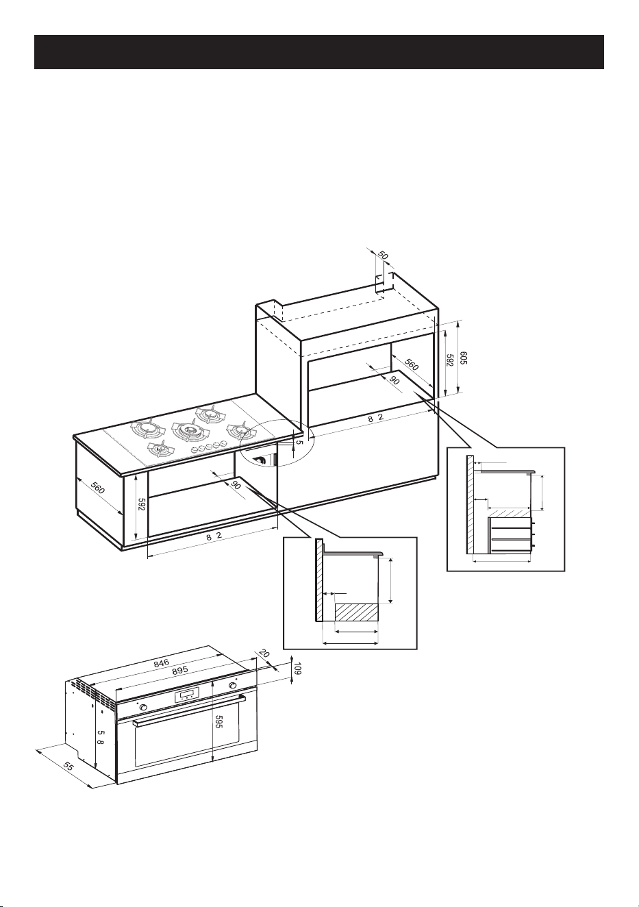
fig. 3
INSTALLATION
Dimensions
• The oven can be installed under a hob or in a column.
• The dimensions of the housing for the oven are given in figure 3.
• Make sure that surrounding materials are heat-resistant.
• Align the oven centrally inside the cabinet then fix it with screws.
• All measurements are in mm .
90
592
470
560
50
90
470
560
592
8
8
5
5
10
INSTALLATION
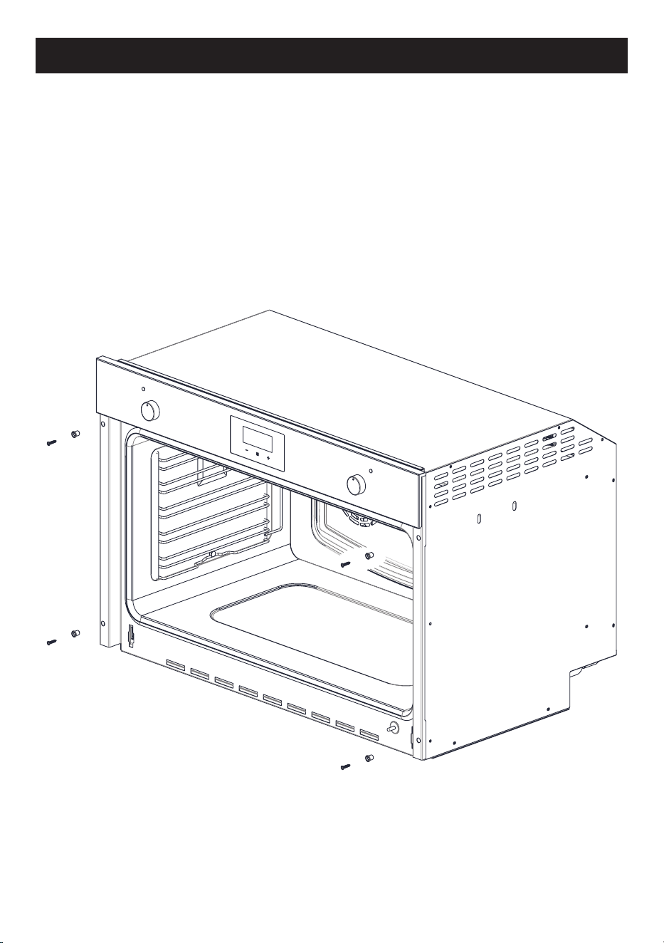
Oven installation
• The oven can be installed under a hob or in a column.
• The dimensions of the housing for the oven are given in figure 3.
• Make sure that surrounding materials are heat-resistant.
• Align the oven centrally with respect to the side walls of the units
surrounding it and fix it in a place the 4 screws with a screwdriver .
• After fixing the screws, fit the plugs that are in the bag with the screws .
Note: for instructional purposes only. Exact model may not be shown.
11
INSTALLATION
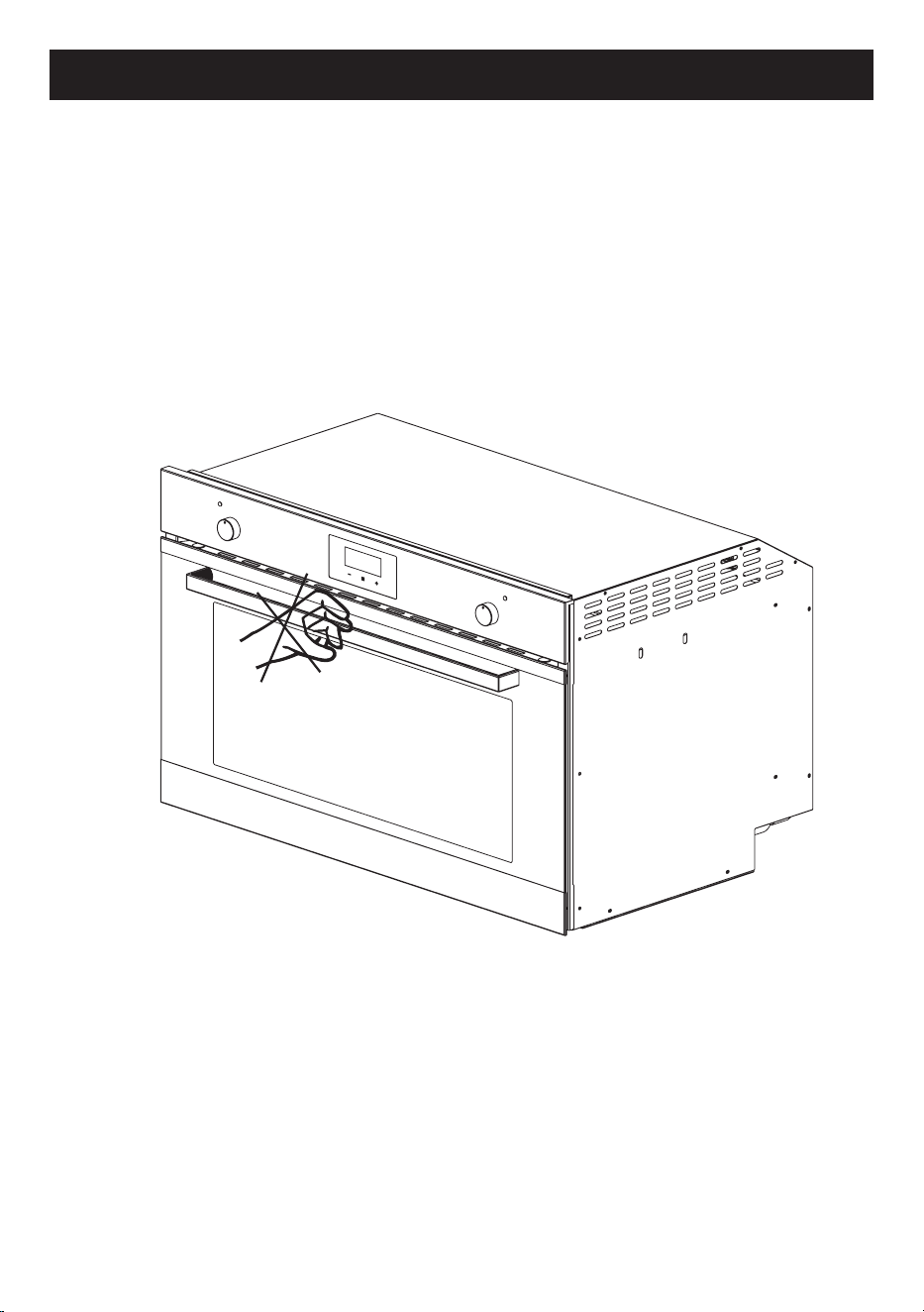
CAUTION
To prevent the oven handle or door glass from breaking, DO NOT lift the oven
by the handle to install it or place it inside the recess. fig.14
fig.14
Note: for instructional purposes only. Exact model may not be shown.
12
DESCRIPTION
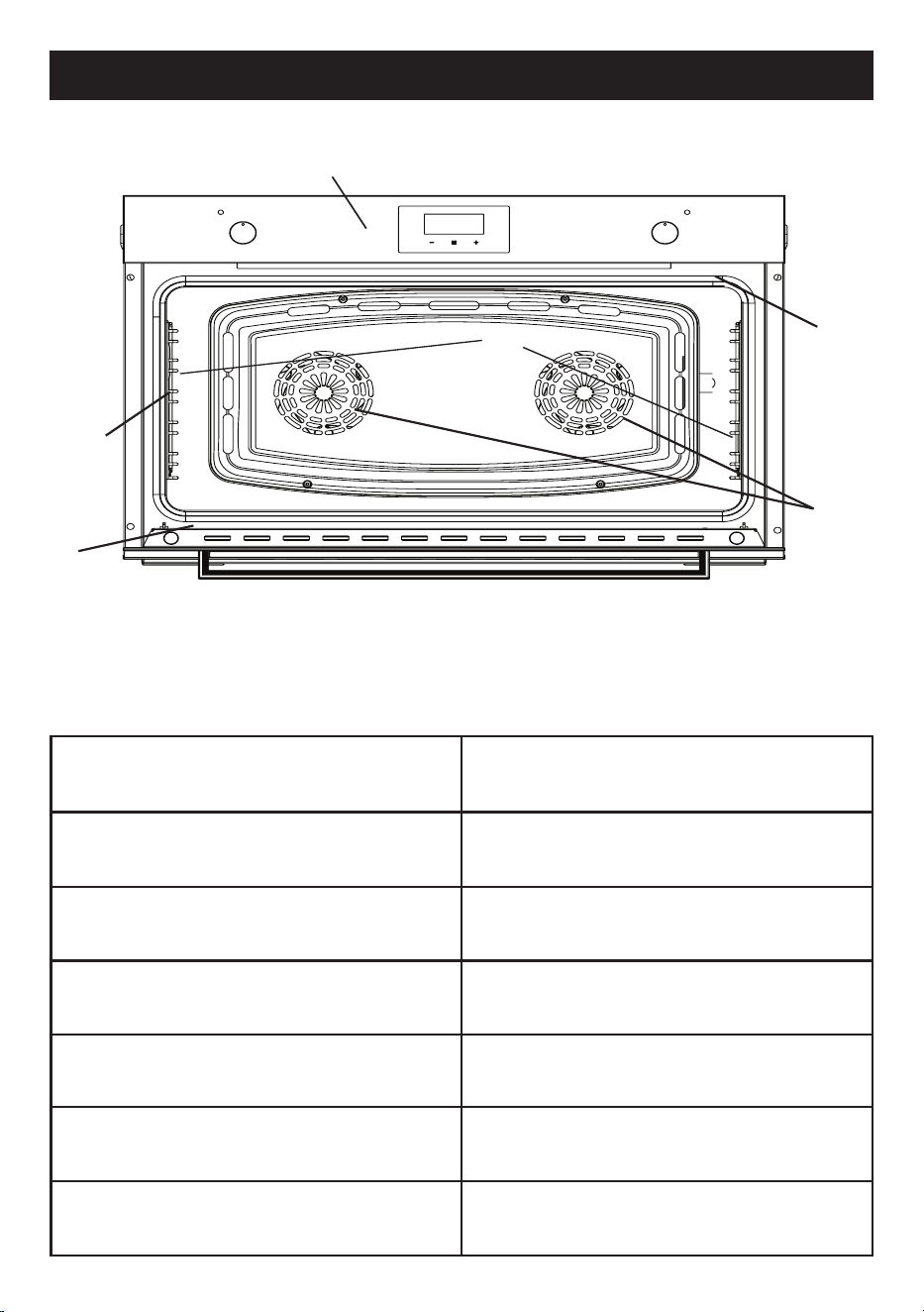
Oven description
1
3
4
5
6
1. Control panel
2. Oven lights
3. Chrome side racks
4. Data label
5. Cooking fans
6. Door seal
COMPONENT NAME
POWER ( Watts )
Upper heating element (top)
1200 W
Lower heating element (bottom)
1800 W
2 FAN circular heating elements
3000 W
Grill 1800 W
Oven lights
80 W
Radial fan 65/32 W
Note: for instructional purposes only. Exact model may not be shown.
2
13
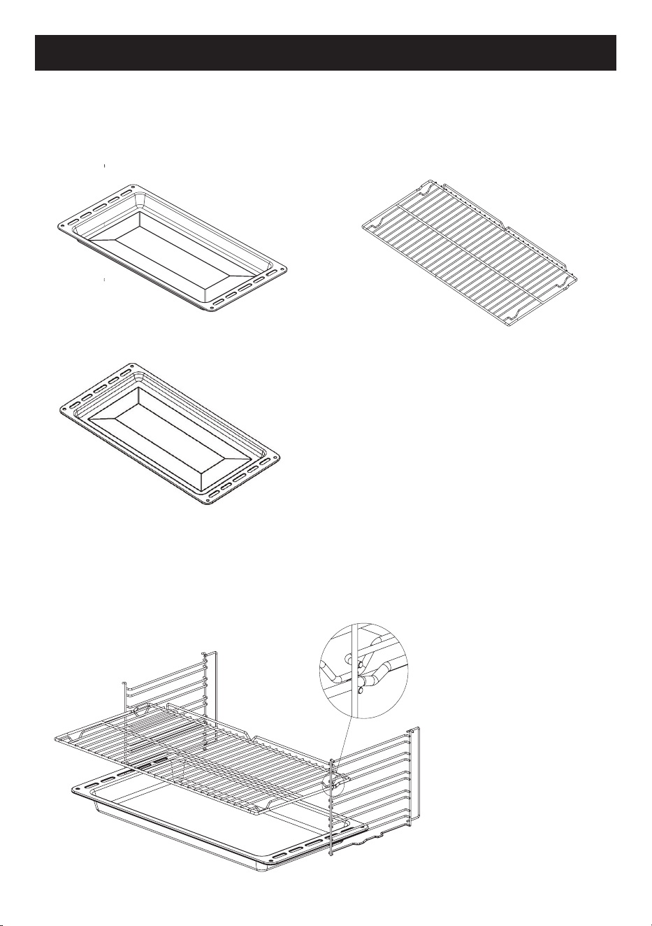
ACCESSORIES
Included Accessories
- Extra Deep Oven Tray
h=50mm
- Oven Tray
Using the accessories
Racks and trays have to
be inserted into the side
guides until they come to
a complete stop.
The mechanical safety
locks that prevent the
rack from being taken out
accidentally must face
downwards and towards
the back of the oven .
Please Note:
• The accessories intended to come into contact with food are made of
materials that comply with the provisions of current legislation
- Chrome Oven Shelves
h=25mm

14
FIRST USE
First use
1. Remove any protective film from the outside or inside of the appliance,
including accessories.
2. Remove the accessories and wash the oven (see page 29).
3. set the temperature regulator to the maximum level. (250°C max).
4. set the function to upper and lower element (conventional) and fan if
available.
5. turn on the oven in this configuration for 30 minutes.
6. open a window for air circulation.
Note:
Smoke and odour from insulating materials and manufacturing
residues may be experienced during this period. If this happens, wait for the
smoke and odour to dissipate before switching off the oven.
After this has been done, and the oven has cooled, clean the inside of the
oven with a slightly damp, soapy soft cloth.
Important:
when opening the oven door, always use the central part of the
handle.
15
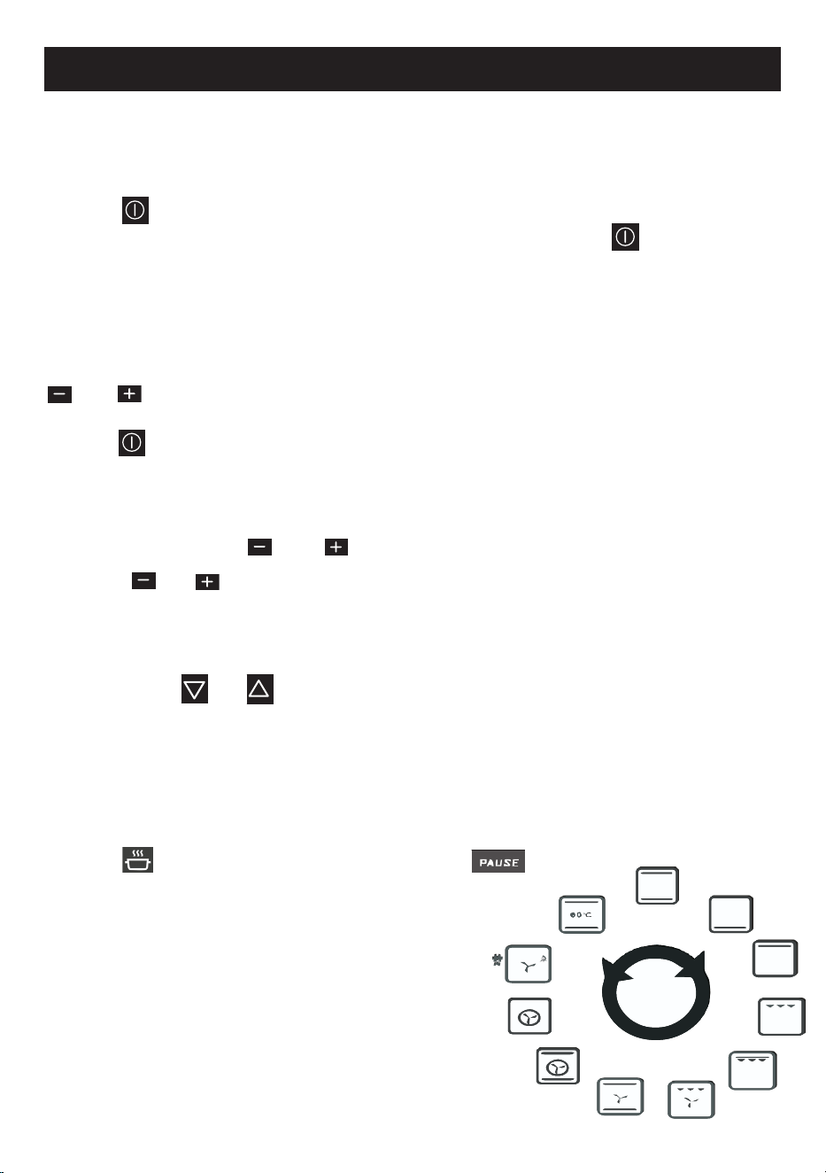
8 FUNCTION MODEL
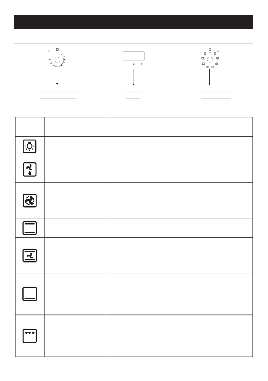
Off
the product won’t work in this position.
Light
turning the knob to the right the switch turns on the
oven light.
Defrost
only cooking fans work in this position, circulates
the air at room temperature around frozen food
and thaws them
Fan Forced
fan and surrounding heater will be
activated.
This program also offers more than one food on
several levels, without the transmission of odors
Conventional
mostly used for cooking in one tray. Roasts both
sides of the food equally, making it crispy.
Fan Bake
circulates hot air inside the oven for more
homogeneous cooking. Used for meals you want
to be soft on the inside and crunchy on the
outside
Base Heat
the heat coming just from the bottom allows you to
complete the cooking of foods that require a higher
bottom temperature without affecting their browning.
Perfect for cakes, pies, tarts and pizzas
Half grill
the heat coming from the grill element gives perfect
grilling results above all for thin and medium thick-
ness meat , gives the food an even browning at the
end of cooking .This function enables large quanti-
ties of food, particulary meat to be grilled evenly.
O
Description
COOKING FUNCTIONS
TEMPERATURE
ADJUSTMENT
DIGITAL
TIMER
FUNCTION
SELECTION

16
8 FUNCTION MODEL
Fan Grill
the heat produced by top heater and grill, is
distributed evenly by the fan.
17
8 FUNCTION MODEL
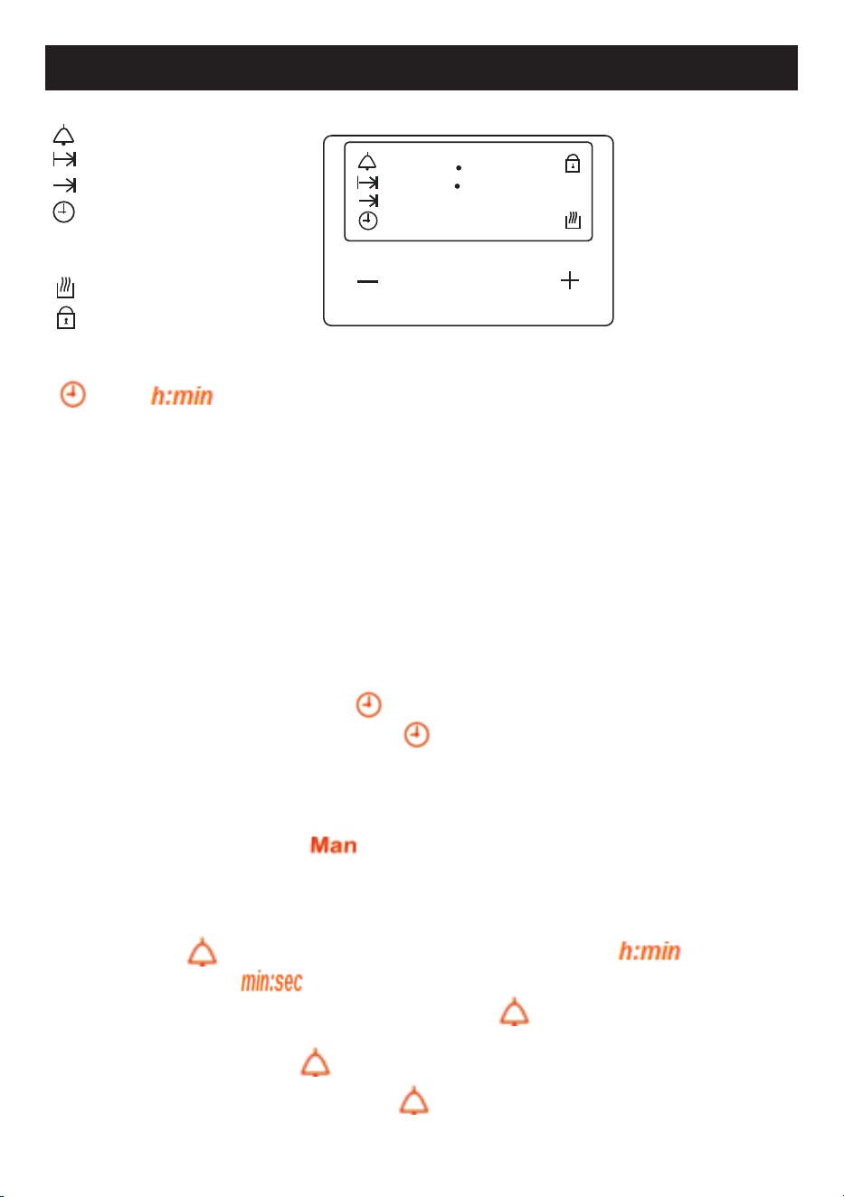
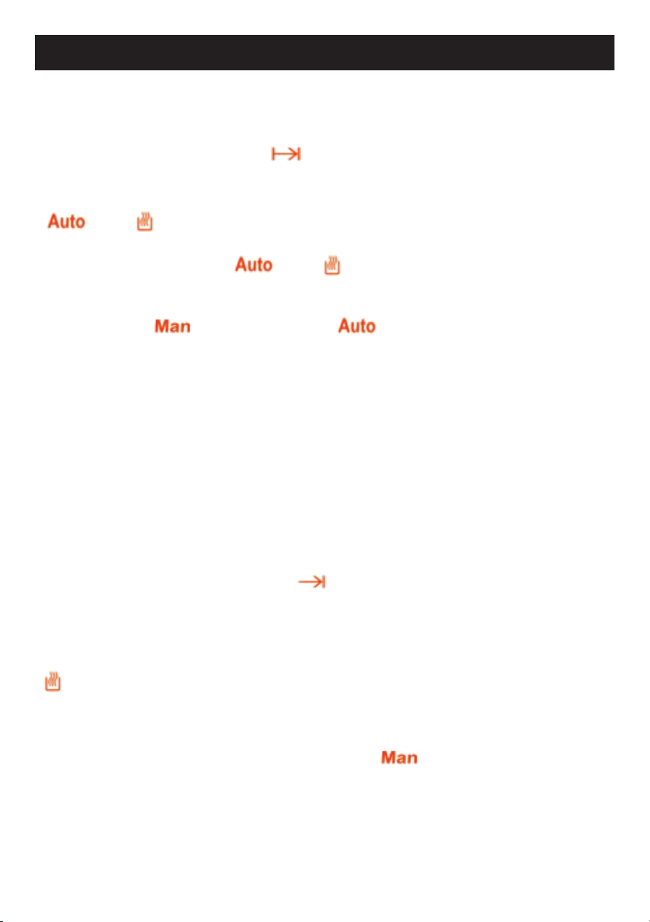
After plugging in or reconnecting to a power source, “12:00”,
and
icon flashes. Any button press enters the time of day setting
menu. Adjust the correct time of day using buttons 1 or 3.
Menu button
The menu button cycles through the minute minder - cooking duration - end of
time – time of day - buzzer tone adjustment menus.
Minus button
Decrease the displayed value.
Plus button
Increase the displayed value.
Setting the time of day (24 h)
• Press and release button 2 until
icon starts flashing. Set the current time
using buttons 1 and 3. After 7 seconds icon disappears, icon stops flashing.
Notice! Time of day setting cancels automatic cooking settings.
Manual Operation
If the programmer is not in semi-automatic or full-automatic mode you can use
oven functions manually, also icon is on the display.
Setting the minute minder
You can activate the minute minder at any time, regardless of the status of other
programmer functions. The adjustable duration ranges from 1 minute to 99 minutes. •
Press button 2, icon starts to flash, the display shows “0.00”
disappears and icon remains on the display.
• Enter the required duration using buttons 1 and 3. remains on the display. After
the set time has elapsed, an audible signal will be heard for approximately 7 minutes
accompanied by a flashing .
disappears, and the display shows the • Press any button to turn the signal off,
time of day.
88 88
Auto Man
h:min
min:sec
M
P
Man
Auto
Minute Minder Icon
Cooking Duration Icon
End of Time Icon
Time of Day Icon
Automatic Cooking Icon Manual
Cooking Icon
Oven Active as Auto Cooking
Child Lock Icon
1
2 3
1 Minus Button
2 Menu Button
3 Plus Button
Using the timer
18
Cooking timer
If the oven is supposed to turn off after a specified duration, cooking timer can be
set. It is named as semi-automatic operation.
• Press and release button 2 until starts to flash.
• Set the cooking duration using buttons 1 and 3, within the range from 1 minute to 23
hours 59 minutes.
and icon light on the display.
• The set time is memorized after about 7 seconds; the current time of day is
shown again on the display. and icons remain on the display.
• Select the required temperature and the oven function.
• When cooking is completed, an audible signal will be heard for approximately 7
minutes, and the icon starts to flash, icon disappears.
Return control and thermostat knobs to the OFF position. Press button 2 to cancel
buzzer signal and press once again to return to manual operation.
Cooking time with delay
If the oven is supposed to turn off at specified time, after having worked for a
specified duration , cooking time and the cooking end time can be set. In this
case, you just give in the cooking duration and the time, when the food should be
ready and the timer calculates when to start cooking. It is named as full-automatic
operation.
Enter cooking duration as described above. (for example say it is 17:30 o’clock
now and cooking duration is set as 1 hour)
• Press and release button 2 until the
icon starts to flash.
• Set the turn-off (cooking end) time using buttons 1 and 3 (for example 19:30). The
maximum cooking end time setting is limited to the current time plus 23 hours 59
minutes.
• Turn the thermostat and function control knobs to the required settings.
icon disappears. Oven will not be switched on until the calculated cooking start
time (according to the example, it is 18:30), that is the difference between the cooking
end time and the cooking duration.
When cooking is completed (according to the example at 19:30), an audible signal
will be heard for approximately 7 minutes, and the icon will flash. Return
control and thermostat knobs to the OFF position.
• Press button 2 to cancel the buzzer signal and press once again to return to manual
operation.
8 FUNCTION MODEL

19
Adjusting the buzzer tone
• Press button 2 until the “LX” (X=1, 2 or 3) flashes on the right two digits.
• Set the tone using buttons 1 and/or 3 to set “L1”, “L2” or “L3”
Note:
Default tone is L3.
Child lock activation/ deactivation
When any adjustment mode is not active, press and hold button 3 about 5 seconds, to
activate/deactivate the key lock, icon appears/disappears on the display
accordingly.
When the child lock is activated, the buttons get locked. Pressing the buttons will
have no effect but it will be heard two beep signal.
Notice! :
In case of main power loss for a short time (about 1.5 minutes), timer maintains
its status.
Child lock status and buzzer tone are memorized independent of the power loss
duration.
8 FUNCTION MODEL
20
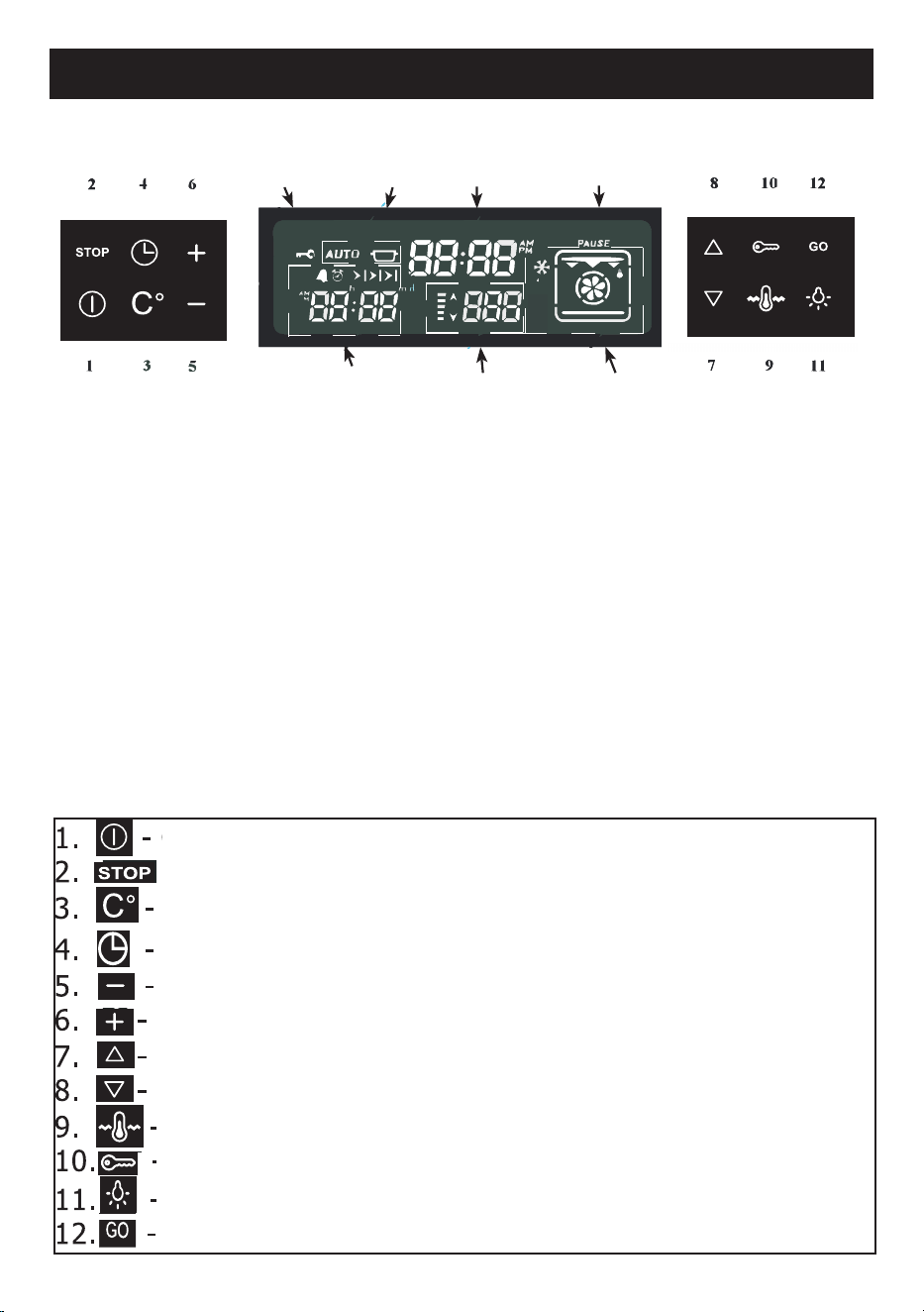
11 FUNCTION MODEL
Timer
Display
Temperature
display
Combined
display
Pause
Time of
the day
Status
display
Child
Lock
Display:
Time of day - Shows the time of day;
Combined display -
Indicates the selected cooking function
Temperature display - Indicates the oven temperature set
Timer display
-
Shows the timer status
Status display - Shows the status of the oven
Pause - Indicates that the cooking with the parameters on the screen is
suspended by the user
Child Lock Indicator - Indicates when the child lock is activated
Touch keys:
On/off activates or deactivates the
display Interrupts any program
Temperature regulation
Timer menu functions
Decrease
Increase
Down-function
regulation
Up-function regulation
Maintaining of temperature
deactivates child lockActivates or
Light on or off
Cooking start key
Description
21
11 FUNCTION MODEL
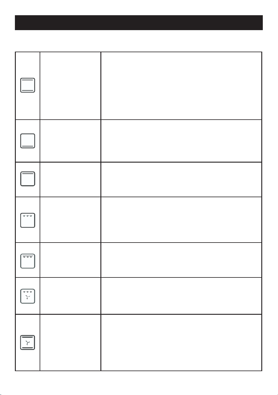
Cooking functions
Conventional
heat, coming simultaneously from above and from
below, makes this system suitable for cooking
particular types of food. Traditional cooking, also
called static, is suitable for cooking only one dish
at a time. Ideal for any type of roast, bread, stuffed
cakes, it is however particularly suitable for fatty
meats such as goose and duck.
Base Heat
the heat coming only from the bottom is used to
complete the cooking of foods that require a higher
basic temperature, without affecting their browning.
Ideal for sweet or savoury tarts, pies and pizzas.
Top heat
the heat coming only from above is used to complete
the cooking of foods that require more cooking on the
top.
Half grill
the heat deriving from the grill element allows ex-
cellent grilling results to be obtained, especially with
medium thickness/thin cuts of meats. This function
allows the uniform grilling of large quantities of food,
especially meat, but also vegetables and fish.
Full grill
this function combines the top down function and the
grill function into one.
Fan Grill
the air produced by the fan softens the decisive heat
wave generated by the grill, allowing optimal grilling
even for very thick foods. Ideal for large cuts of meat.
Fan Bake
operation of the fan, combined with traditional cook-
ing, ensures uniform cooking even with complex reci-
pes. Ideal for biscuits and cakes, even cooked
simulta-neously on multiple levels. (For multi-level
cooking it is advisable to use the 2nd and 4th shelves)
22
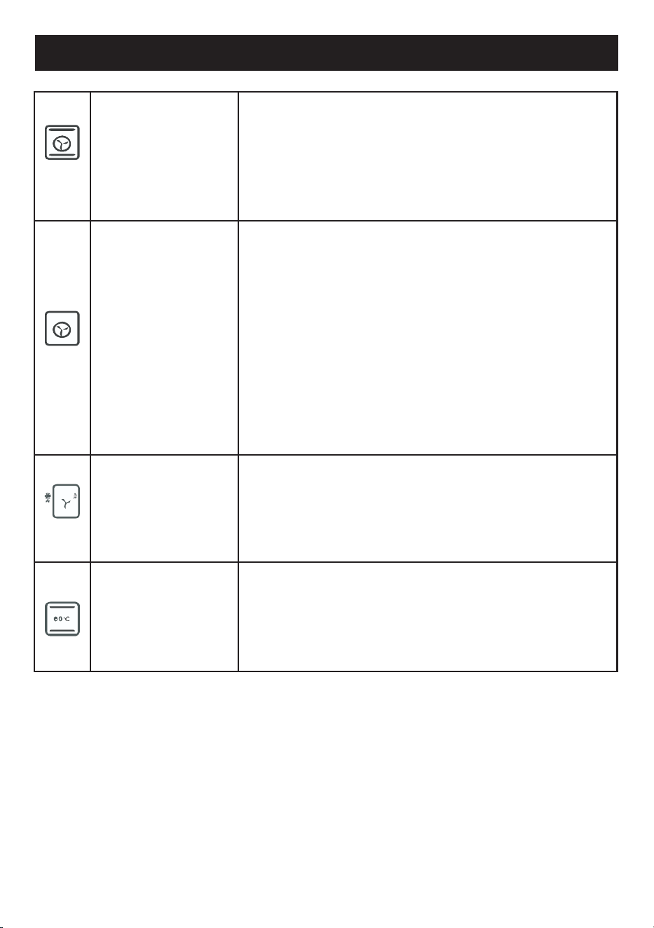
11 FUNCTION MODEL
Turbo
the combination of fan-assisted cooking with
traditional cooking allows different foods to be
cooked quickly and effectively on several levels,
without smells or flavours being transmitted. Ideal
for large-volume foods that require intense cooking.
Fan Forced
the combination of the fan and the circular heating
element (incorporated in the rear part of the cooking
compartment) allows the cooking of different foods
on several levels, provided they require the same
temperatures and the same type of cooking. The cir-
culation of hot air ensures instant and uniform heat
distribution.
It will be possible, for example, to cook fish, vegeta-
bles and biscuits at the same time (on several levels)
without mixing odours and flavours.
Defrost
this function allows food to be defrosted. It is advis-
able to place the food without packaging in a con-
tainer without a lid on the first shelf of the cooking
compartment.
Avoid stacking foods.
Keep Warm
this function is used to ensure a constant tempera-
ture ranging from 60° to 90°. It is ideal to have conti-
nuity in cooking while keeping the heat low.
23
11 FUNCTION MODEL
Operation
Control activation or deactivation
The key activates or deactivates the control (regardless of the child lock). When the
for 1 second
control is deactivated, the screen is completely blank. Pressing the key
activates the control. The current time of day appears on the display.
Note:
in the event of a power failure, the current time of day will no longer be correct. A
flashing 0:00 will appear on the time of day display. No features of the control will be
visible without setting the time of day. The correct time can be adjusted with the
and
keys.
Pressing for 1 second, depending on whether it is ON or OFF, the control/card is
activated or deactivated.
Setting time of the day
Touch and hold both the
and buttons until the hour digits start flashing.
Using the or ,keys, set the correct time.
Wait 7 seconds, the flashing stops, then the adjustment is completed.
Selection a cooking function
Using one of the or , keys it is possible to scroll through the function menu.
The current function will flash on the function dis-play
for 7 seconds and the default cooking temper-ature
assigned to this function will appear on the
temperature display (Note: for certain functions,
temperature control is not possible and the tem-
perature display is empty .
if the key is constant on the status display, while
is flashing, it indicates that it is pos-sible to start
cooking but that cooking has not yet started.
24
11 FUNCTION MODEL
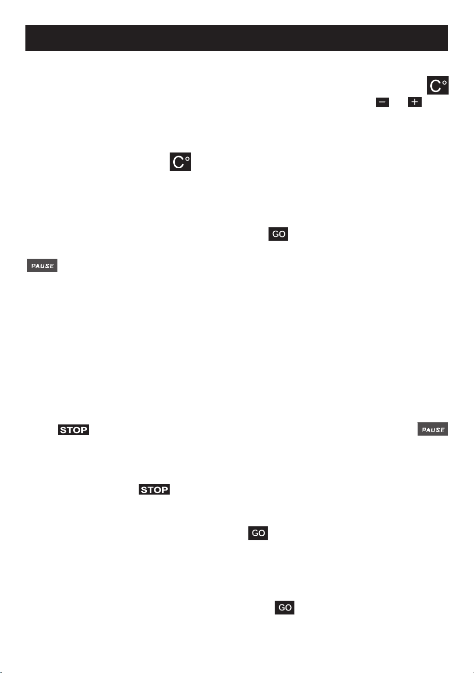
Modication of the assigned default cooking temperature
The temperature setting on the temperature display can be changed by touching the
key. The temperature display starts to ash. To set the desired value use or in 5
degree steps.
Note: to replace the default temperature setting for this function with this tempera-
ture set permanently, touch for approximately 5 seconds, until a beep is heard.
The factory-set default temperature for this function is now permanently changed.
Manual cooking
Once a function has been selected, touching the key, cooking begins with a tem-
perature adjustment on the temperature display (if present).
disappears and the cooking time begins to appear on the timer display. Cook-
ing will continue until it is manually terminated by the user or until the maximum per-
mitted cooking time, depending on the selected cooking temperature, has elapsed.
With half and complete automatic cooking, as described below, cooking is automati-
cally terminated according to the parameters entered by the user before cooking
(tapping)
To suspend, modify or terminate cooking
The contact during cooking interrupts the cooking process and
starts ashing, while other parts of the display remain unchanged. All oven and turbo
fan heating elements are temporarily disabled. Cooking is suspended.
To nish cooking, tap again; all the cooking indications on the display disap-
pear. The temperature display will indicate the residual heat, if present (See: indication
of residual heat).
Note: after cooking is nished, touching the key will restore the previous func-
tion and the temperature settings on the screen; with a second tap, it is possible to
start cooking again.
To change the cooking parameters (function, temperature, etc.), use the appropriate
buttons as described in this document. Tapping
will restar
t cooking with the
modied parameters.
25
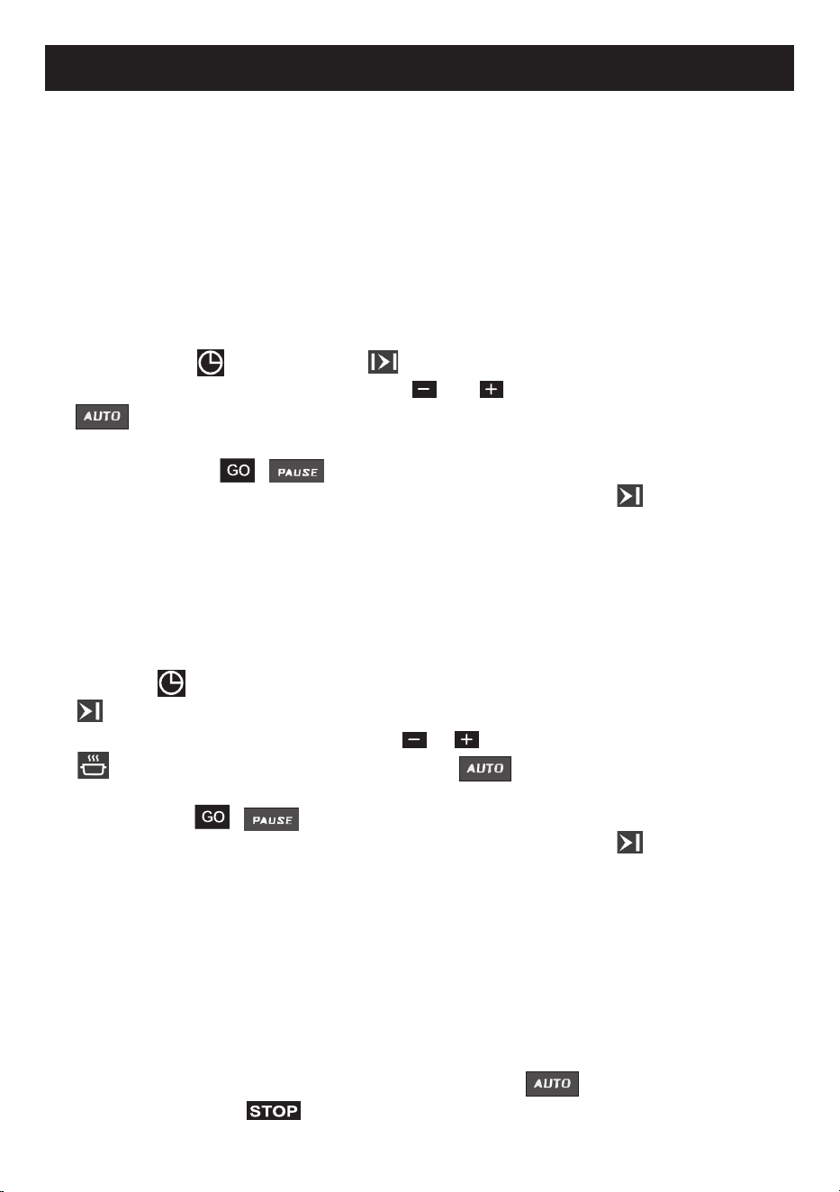
11 FUNCTION MODEL
Automatic cooking
Automatic cooking means that cooking will end automatically based on the param-
eters of the cooking function and the temperature selected.
Semi-automatic cooking
This method is used to start cooking immediately, entering the desired cooking time.
1) Select the desired function and adjust (if necessary) the temperature as described
earlier in this document.
2) Press the key . At this point will ash on the timer screen.
3) Set the desired cooking time with the and keys.
appears on the status display. (if the duration is increased to 0:00, two
warning beeps will occur).
4) Pressing the key , disappears and cooking starts. The end of cooking
time is shown on the timer display, together with the symbol .
Automatic cooking
This method is used if the food is intended to be ready at a particular future time.
Therefore, this method is also called “delayed cooking”.
1) Perform steps 1 to 3 of the half automatic cooking (setting the cooking time).
2) Press the key again .
ashes on the timer screen together with the current end cooking time.
3) Adjust the desired end time with the e keys .
on the status display disappears, while does not, indicating that de
layed cooking has been programmed and consequently does not start immediately.
4) Press the key , disappears and cooking starts. The end of cooking
time is shown on the timer display, together with the symbol .
During cooking
The 5 bars on the temperature display indicate the actual oven temperature. Each bar
is assigned to one fth of the regulated value. The high-arrow next to the bars ashes
when the heating elements are active at that time.
End of automatic cooking
After
cooking has nished automatically, the temperature display will indicate the re-
sidual heat, if present (See: indication of residual heat),
will ash and will sound
for 7 minutes. Tapping
inter
rupts the sound.
26
11 FUNCTION MODEL
Residual heat indication
After cooking has been completed manually or automatically, if the internal tempera-
ture of the oven is above 60°C, the ‘down arrow’ on the right side of the heat bars
ashes every 2 seconds and also “hot” is shown on the display of the temperature. At
this point every one of the 5 heat bars symbolises 60°C. This indication remains on
until the oven temperature drops below 60°C.
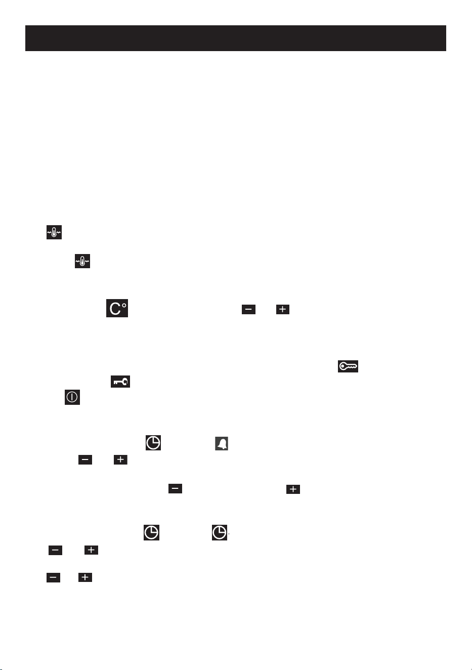
Special features :
Maintaining of temperature
To ensure a constant temperature ranging from 60° to 90° to maintain food, select
the icon on the top down+bottom down function (the eleventh function), which
is the only one that allows this possibility .In all the other functions it is not provided,
in fact if is selected when in another function, the top down+bottom up func-
tion is automatically shown on the display and the maintaining of temperature starts.
Attention: the maintaining of temperature is not predened. It is possible to choose
by pressing the key and by using the or keys the desired temperature,
between 50° and 90°.
Child lock
The child lock can be activated or deactivated by tapping the key for 1 second
until the symbol appears on the screen. When the child lock is activated, no key
except is accepted.
Minute counter allarm
Touch and release the key until appears flashing. See the time in minutes,
using the or keys. The flashing will stop after 7 seconds; an audible alarm
lasting 7 minutes will be produced after the set time has expired. This alarm can be
interrupted by touching the key or touching the key.
Alarm
Touch and release the key until appears flashing. See the alarm time, using
the
or
keys; the flashing stops after 7 seconds. An audible alarm will be
produced at the end of the adjusted time. This alarm can be interrupted by touching
the
or .
27
11 FUNCTION MODEL
Error Codes
When
situations
occur
that
prevent
normal
operation,
the
device
goes
into
error
mode. The device is in the standby state, but an error code is shown on the time of
day display. Even if the error is recovered, this code will remain on the display until
the
key is touched. There are a total number of 8 error codes:
Error
Code
Definition of error and possible causes
ERR 1
Communication error between the UM and PM cards.
- DKB2-XX-POC400 the data cable connector may be detached
on both sides.
- DKB2-XX-POC400 the data cable may be defective.
- POC 400 PM may be defective.
ERR 2
Oven cavity circuit temperature sensor open.
- PT-1000-M2-XXX the sensor connector may be detached on the
PM.
- PT-1000-M2-XXX the sensor may be defective.
- POC 400 PM may be defective.
ERR 3
Oven cavity circuit temperature sensor open.
- PT-1000-M2-XXX the sensor may be defective.
- POC 400 PM may be defective.
ERR 4
Front panel temperature limit exceeded.
- The UM temperature has exceeded the limit (100C°), check the
POC 400 UM cooling fan, it may be faulty.
ERR 5
PM temperature limit exceeded.
- The temperature of the PM has exceeded the limit (105°).
- POC 400 PM may be defective.
ERR 6
UM heat sensor error.
- POC 400 UM may be defective.
ERR 7
PM heat sensor error.
- POC 400 PM may be defective.
ERR 8
No temperature adjustment .
- Check the heating elements and connections.
- POC 400 PM may be defective.

28
11 FUNCTION MODEL
In the case of an error message
If these errors cannot be solved by tapping the button, try to disconnect
the oven from the mains and connect it again after 2 minutes.
If this does not work, contact the nearest service centre.
PROGRAMMABLE OPTIONS
Acoustic signal
There are three acoustic tones that can be selected.
Touch the key for 5 seconds, the time display shows the currently valid tone as
“TN 1” (high) or “TN 2 (medium)” or “TN 3 (low)”. The valid tone can be changed
by touching the key within 7 seconds of the last setting.
The default tone is “TN 1”.
Key sound
There are three key sound options that can be selected.
Touch the key for 5 seconds, the time display shows the currently valid key tone
as “bt tn” (beep tone) or “cl tn” (click Tone) or “nt” (no tone). The valid key sound
can be changed by touching the key within 7 seconds of the last setting.
The default key sound is “bt tn”.
Time of day 24h/12h mode: the default mode is 24 hours
For the 12h AM/PM mode, touch both the and keys for 5 seconds. The
modes change and an acoustic signal occurs. Vice-versa perform the same action.
29
CLEANING AND MAINTENANCE
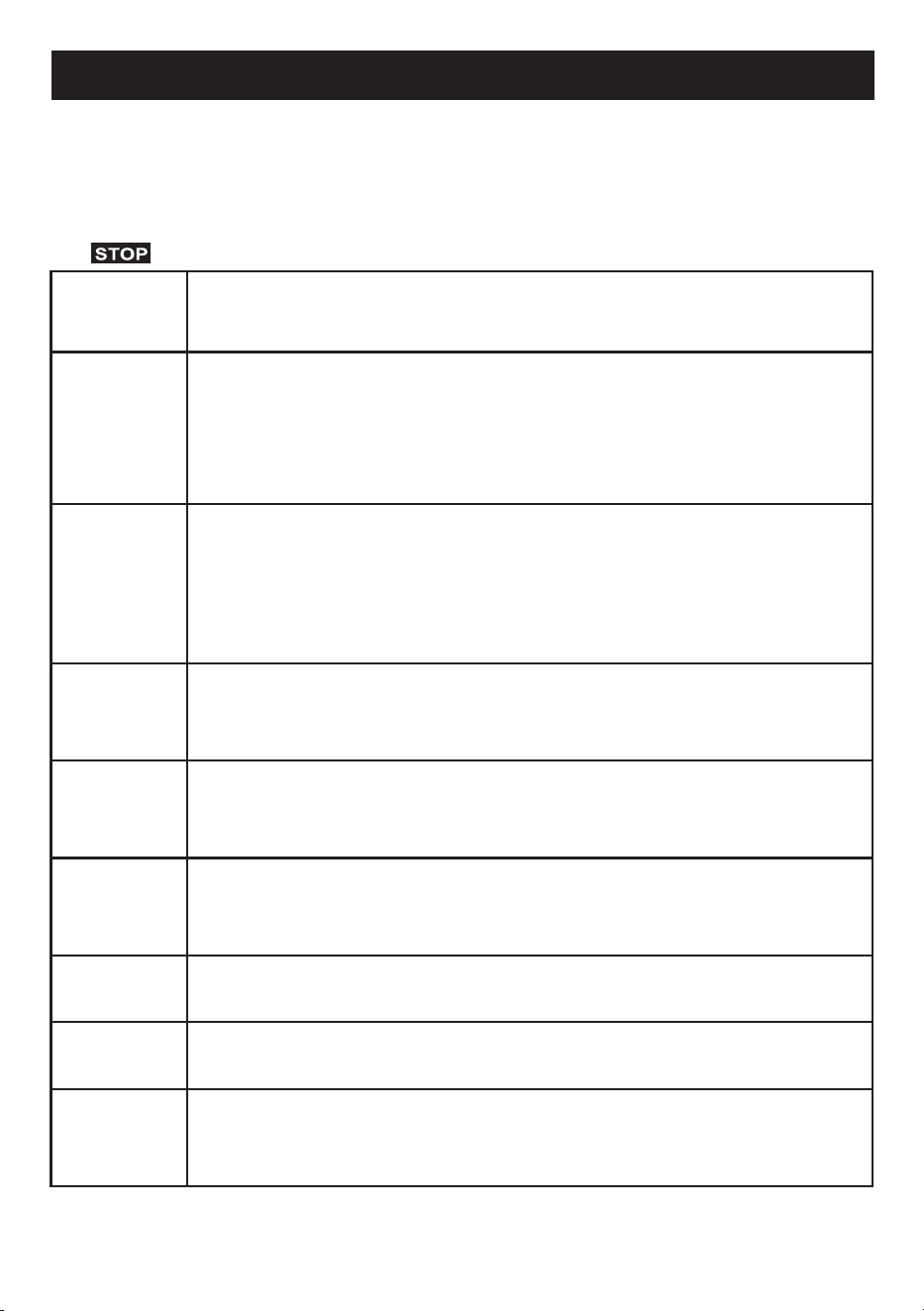
Warnings
• As a safety precaution, before proceeding with any cleaning operation of the oven,
always unplug the appliance from the mains socket or remove the appliance’s
power supply line.
• It is also recommended to avoid the use of acidic or alkaline substances (lemon
juice, vinegar, salt, tomatoes, etc.)
• Avoid using chlorine, acidic or abrasive products especially for the cleaning of
painted walls.
• Do not use steam jets to clean the appliance .
• Do not use harsh abrasive cleaners or sharp metal scrapers to clean the oven
door glass, since they scratch the surface, which may result in shattering of the
glass .
Before each cleaning, please remove all the accessories including the side grilles (as
g.7).
The oven must be cleaned thoroughly with soap and water and fully rinsed.
Heat the oven for approximately 20 minutes at maximum temperature; all the
processing fat residues that could cause unpleasant smells during cooking will be
eliminated .
g.7
Cleaning inside the oven
30
CLEANING AND MAINTENANCE
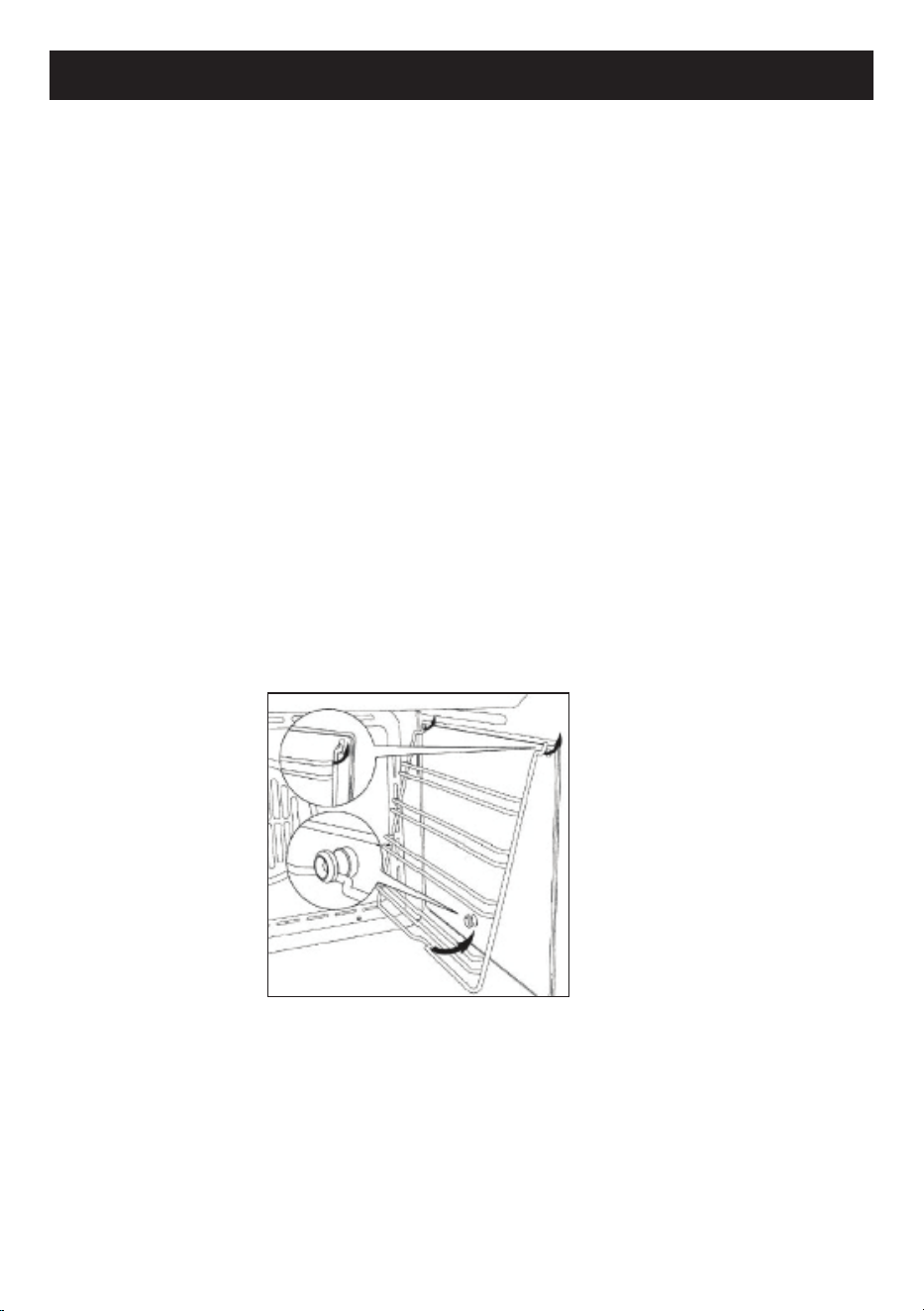
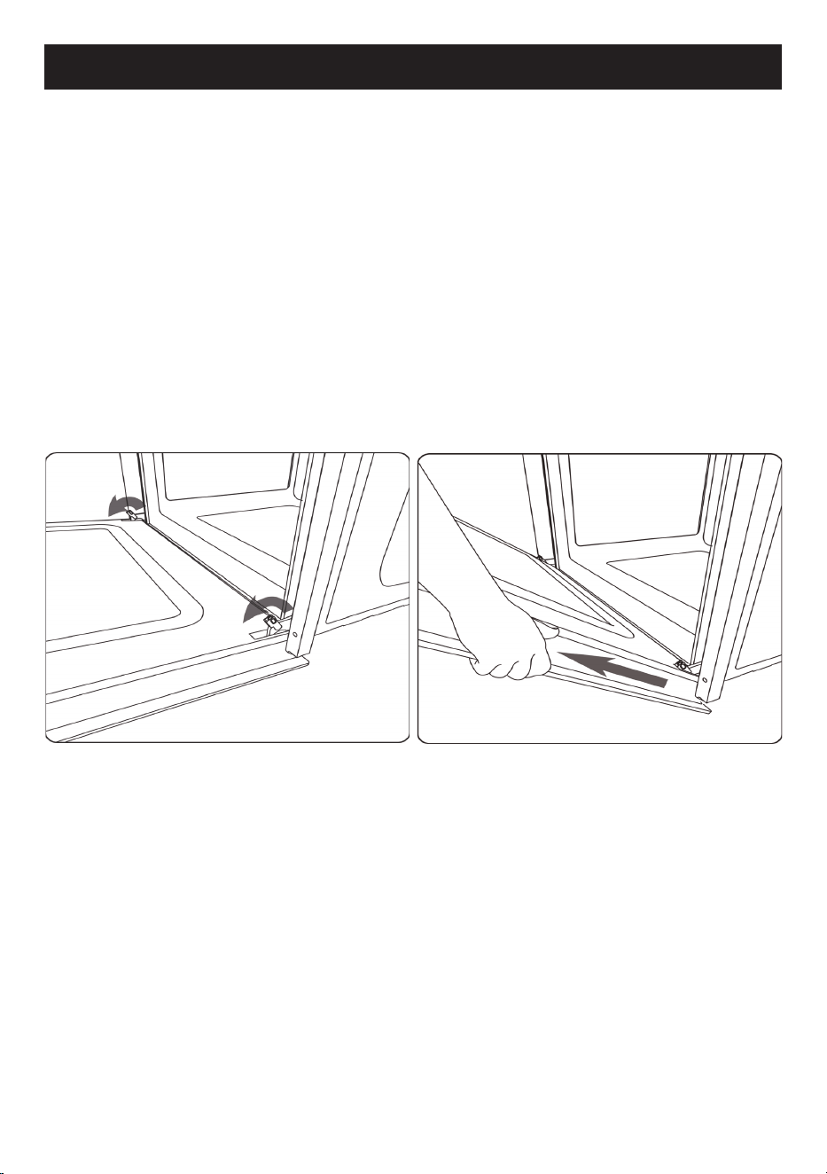
Removing the oven door
For easier cleaning it is recommended to remove the door and place it on a tea towel.
To remove the door proceed as follows :
• Open the door completely ;
• Lift the two levers indicated in figure 10 ;
• Close the door as far as the first stop caused by the previously raised levers ;
• Lift the door upwards and outwards from the oven to extract it from its mountings.
Figure11.
To replace the door, insert the hinges in the appropriate mountings and then bring
the two levers back to their closed position.
g.10 g.11
31
CLEANING AND MAINTENANCE
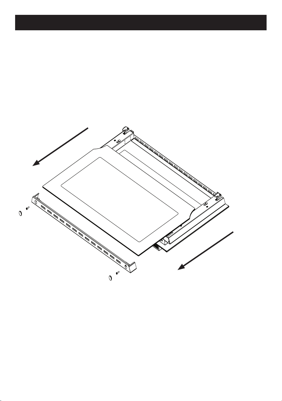
Internal glass cleaning
To clean the inside glass door, unscrew the two screws located above the door, gure
12, and carefully remove the glass.
To reassemble the glass, insert the glass up to the stop on the bottom, replace the
glass xing bracket and tighten the two screws.
g. 12
32
CLEANING AND MAINTENANCE
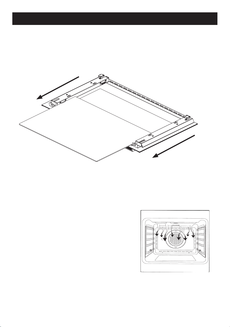
Third glass cleaning
Some ovens have a third glass, located between the ovens door and internal glass.
Once the internal glass has been removed, the third glass can be removed in the
same way, following the direction of the arrows.
Cooling fan
The cooling fan is present both in the
ventilated
oven and in the static one.
It is positioned in the top of the oven and creates
a circle of cooling air around the appliance,
exiting the slots under the oven control panel.
The cooling fan is activated when the
oven temperature rises above 85°C.
It is deactivated when the oven temperature
falls to 75°C.
g. 13

MANUFACTURER GUARANTEE
This warranty is provided in Australia by Glen Dimplex Australia Pty Limited ABN 69 118 275 460
(Phone number 1300 556 816) and in New Zealand by Glen Dimplex New Zealand Limited NZBN
9429000069823 (Phone number 09 274 8265) in respect of the Belling Design product.
1. Belling Design Express Warranty
Subject to the
exclusions below, we warrant that the product will not have any electrical or
mechanical breakdowns within:
a)
In the case of
Belling Design
products used for personal, domestic or household purposes,
a period of
5
years
from the date the product is purchased as a
brand-
new
product from a
retailer located in Australia
/ New Zealand.
b) In the case of Belling Design products used for purposes other than personal, domestic or
household purposes (including business or commercial use), a period of 90 days from the
date the product is purchased as a brand-new product from a retailer located in Australia /
New Zealand. Belling Design products are designed and intended for domestic use only;
and
c) All warranty repairs must be carried out by Glen Dimplex or their nominated service agent
Note: warranty periods detailed above may vary in line with agreements with select retail and
builder partners and may differ between Australia and New Zealand.
The benefits conferred by this express warranty are in addition to the Consumer Guarantees
referred to in section 3 and any other statutory rights you may have under the Australian / New
Zealand Consumer Law and/or other applicable laws.
2. Warranty exclusions
This express warranty does not apply where:
a) The product has been installed, used or operated otherwise than in accordance with the
product manual or other similar documentation provided to you with the product;

b) The product requires repairs due to damage resulting from accident, misuse, incorrect
installation, insect or vermin infestation, improper liquid spillage, cleaning or maintenance,
unauthorised modification, use on an incorrect voltage, power surges and dips, voltage
supply problems, tampering or unauthorised repairs by any persons, use of defective or
incompatible accessories or exposure to abnormally corrosive conditions, events
independent of human control which occurred after the goods left the control of Glen
Dimplex;
c) The repair relates to the replacement of consumable parts such as fuses and bulbs or any
other parts of the product which require routine replacement;
d) You are unable to provide us with reasonable proof of purchase for the product;
e) the breakdown occurs after the expiry of the express warranty period set out in section 1 or
f) the product was not purchased in Australia / New Zealand as a brand-new product.
3. Consumer guarantees
Our goods come with guarantees that cannot be excluded under the Australian / New Zealand
Consumer Law. You are entitled to a replacement or refund for a major failure and for compensation
for any other reasonably foreseeable loss or damage. You are also entitled to have the goods
repaired or replaced if the goods fail to be of acceptable quality and the failure does not amount to a
major failure.
4. How to make a claim
You may make a claim under this warranty through our website, contacting our customer care line
or via email. Contact details for Glen Dimplex Australia and New Zealand can be found at the end of
this document
To make a valid claim under this warranty, you must:
a) Lodge the claim with us as soon as possible and no later than 14 days after you first become
aware of the breakdown;
b) Provide us with the product serial number;
c) Provide us with reasonable proof of purchase for the product. This can take the form of a
store receipt, new home handover form or other payment receipt documentation; and

d) If required by us, provide us (or any person nominated by us) with access to the premises at
which the product is located at times nominated by us (so that we can inspect the product).
5. Warranty claims
If you make a valid claim under this warranty and none of the exclusions set out in section 2 apply,
we will, at our election, either repair the product or replace the product with a product of identical
specification (or where the product is superseded or no longer in stock, with a product of as close a
specification as possible).
Goods presented for repair may be replaced by refurbished goods of the same type rather than
being repaired. Refurbished parts may be used to repair the goods.
Products are designed and supplied for normal domestic use. We will not be liable to you under this
warranty for business loss or damage of any kind whatsoever.
Glen Dimplex Australia Pty Ltd Glen Dimplex New Zealand Ltd
www.glendimplex.com.au www.glendimplex.co.nz
Australia New Zealand
Ph: 1300 556 816 Ph: 09 274 8265
customer.care.ha@glendimplex.com.au nztechserv@glendimplex.co.nz

NOTES
______________________________________________________
______________________________________________________
______________________________________________________
______________________________________________________
______________________________________________________
______________________________________________________
______________________________________________________
______________________________________________________
______________________________________________________
______________________________________________________
______________________________________________________
______________________________________________________
______________________________________________________
______________________________________________________
______________________________________________________
______________________________________________________
______________________________________________________
______________________________________________________
______________________________________________________
READ THE INSTRUCTION BOOKLET BEFORE INSTALLING AND USING THE APPLIANCE.
The manufacturer will not be responsible for any damage to property or to persons caused by
incorrect installation or improper use of the appliance.
The manufacturer is not responsible for any inaccuracies, due to printing or transcription errors,
contained in this manual. In addition, the appearance of the figures reported is also purely
indicative.
The manufacturer reserves the right to make changes to its products when considered necessary
and useful, without affecting the essential safety and operating characteristics.
Glen Dimplex constantly seeks ways to improve the specifications and designs of their products.
Whilst every effort is made to produce up to date literature, this document should not be regarded
as an infallible guide. Actual product only should be used to derive cut out sizes.
All appliances must be installed by a qualified person/s with adherence to the relevant electrical,
plumbing and building codes, with compliance being issued as required by state or national
legislation.
Additionally, all upright cookers must have the anti-tilt device installed correctly in adherence to the
relevant standards by a licenced installer.
For maximum effectiveness and efficiency all rangehoods should be installed with the use of
ductwork, by a licenced installer with adherence to the relevant state and national building codes
and regulations.
All Glen Dimplex appliances are for Domestic use only, and must be installed by a licence installer
into Domestic Applications only, without exception and to the required Authorities guidelines. Any
installation outside of this will VOID warranty. Alfresco areas are not a Domestic application.
Distributed by:
Glen Dimplex Australia Pty Ltd Glen Dimplex New Zealand Ltd
For full terms and conditions, or to register your product warranty, please visit our website:
www.glendimplex.com.au www.glendimplex.co.nz
For service advice, please contact the Customer Care Centre by phone or email below.
Australia New Zealand
Ph: 1300 556 816 Ph: 09 274 8265
customer.care.ha@glendimplex.com.au
nztechserv@glendimplex.co.nz
VERSION 1 REVISION 20200313
