BLACKSTONEPRODUCTS.COM/SUPPORT
ENGLISH
SAFETY ALERT KEY
dANGeR
Indicates a hazardous situation
that, if not avoided, will result in
death or serious injury�
CAUTIoN
Indicates a hazardous situation
that, if not avoided, could result
in minor or moderate injury�
WARNING
Indicates a hazardous situation
that, if not avoided, could result
in death or serious injury�
NOTICE
Indicates information considered
important, but not hazard-
related (e�g� messages related to
property damage)�
oWNeR’S MANUAl
IMPORTANT:
This instruction manual contains important
information necessary for the proper assembly and safe
use of the appliance.
Read and follow all warnings and instructions before
assembling and using the appliance.
Follow all warnings and instructions when using
the appliance.
Keep this manual for future reference.
Installer/Assembler: leave these instructions with the consumer�
For the latest version of this manual,
scan this code or visit
BlackstoneProducts.com/support
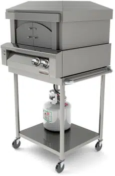
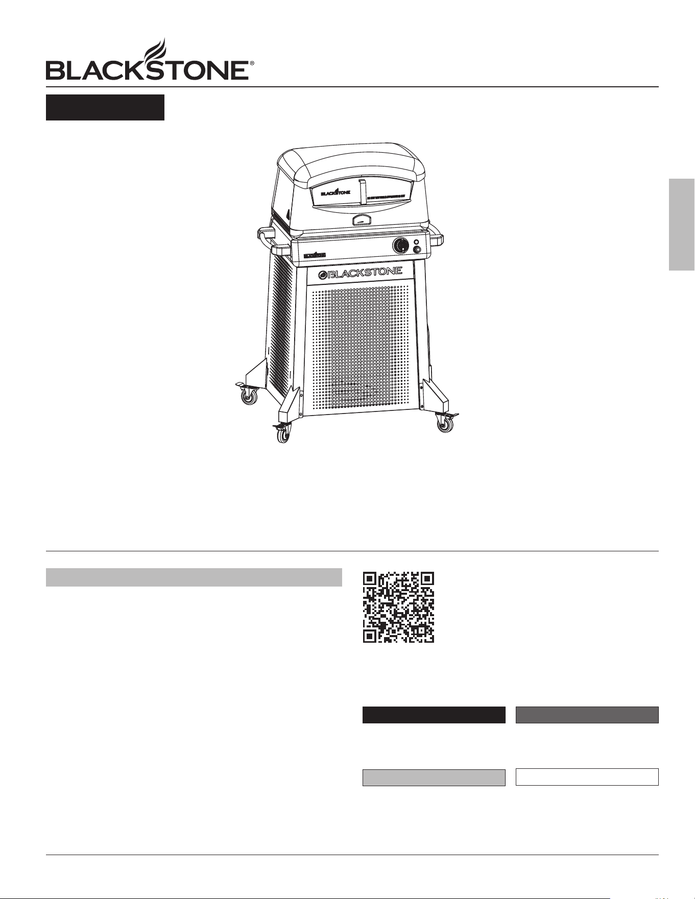
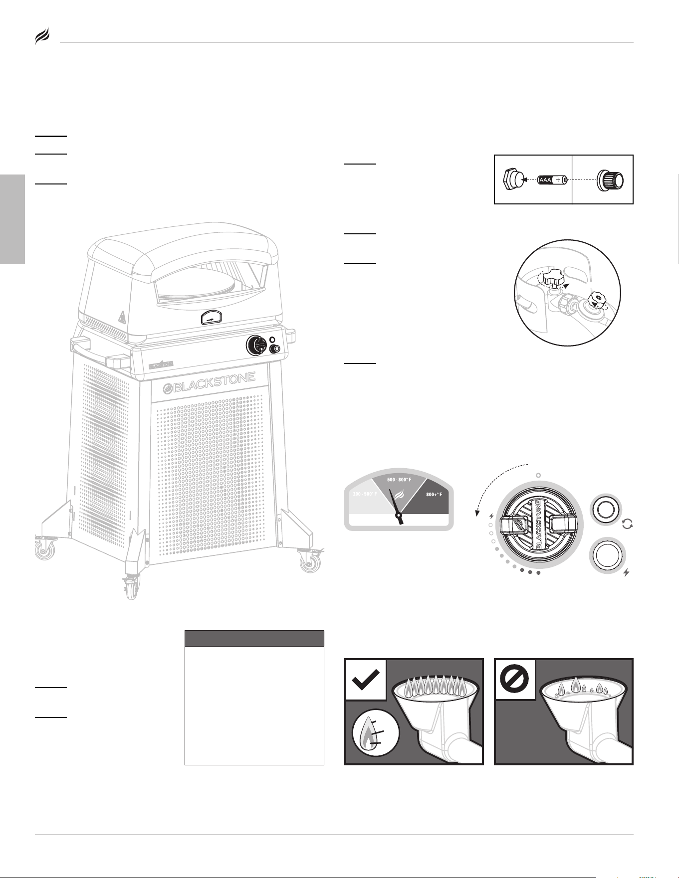
Model: 6825
v11
PIZZA OVEN
WITH MOBILE CART
TABLE OF CONTENTS
IMPoRTANT SAFeTY INFoRMATIoN � � � � � � � � � � � � � � � � � � � � � � �02
ACTIVATe YoUR WARRANTY � � � � � � � � � � � � � � � � � � � � � � � � � � � � � � � � 03
ASSeMBlY GUIde � � � � � � � � � � � � � � � � � � � � � � � � � � � � � � � � � � � � � � � � � � � � � � 04
USING YoUR BlACKSToNe � � � � � � � � � � � � � � � � � � � � � � � � � � � � � � � � � � � 12
TRoUBleSHooTING � � � � � � � � � � � � � � � � � � � � � � � � � � � � � � � � � � � � � � � � � � � � 17
01
ENGLISH
BLACKSTONEPRODUCTS.COM/SUPPORT
OWNER’S MANUAL | IMPORTANT SAFETY INFORMATION
GAS APPLIANCE SAFETY
• The use of alcohol, prescription, or non-prescription drugs may
impair the consumer’s ability to properly assemble or safely
operate the appliance�
• Keep children and pets away from the appliance at all times�
• Have a type BC or ABC fire extinguisher readily available�
DO NOT USE FOR PURPOSES OTHER THAN INTENDED:
• do NoT modify this appliance�
• do NoT use for commercial cooking�
• do NoT use this appliance as a heater�
THIS APPLIANCE SHALL BE USED OUTDOORS ONLY.
• do NoT use this appliance inside buildings, garages, or any other
enclosed area�
• do NoT install this appliance in or on a boat�
• do NoT install this appliance in or on a recreational vehicle�
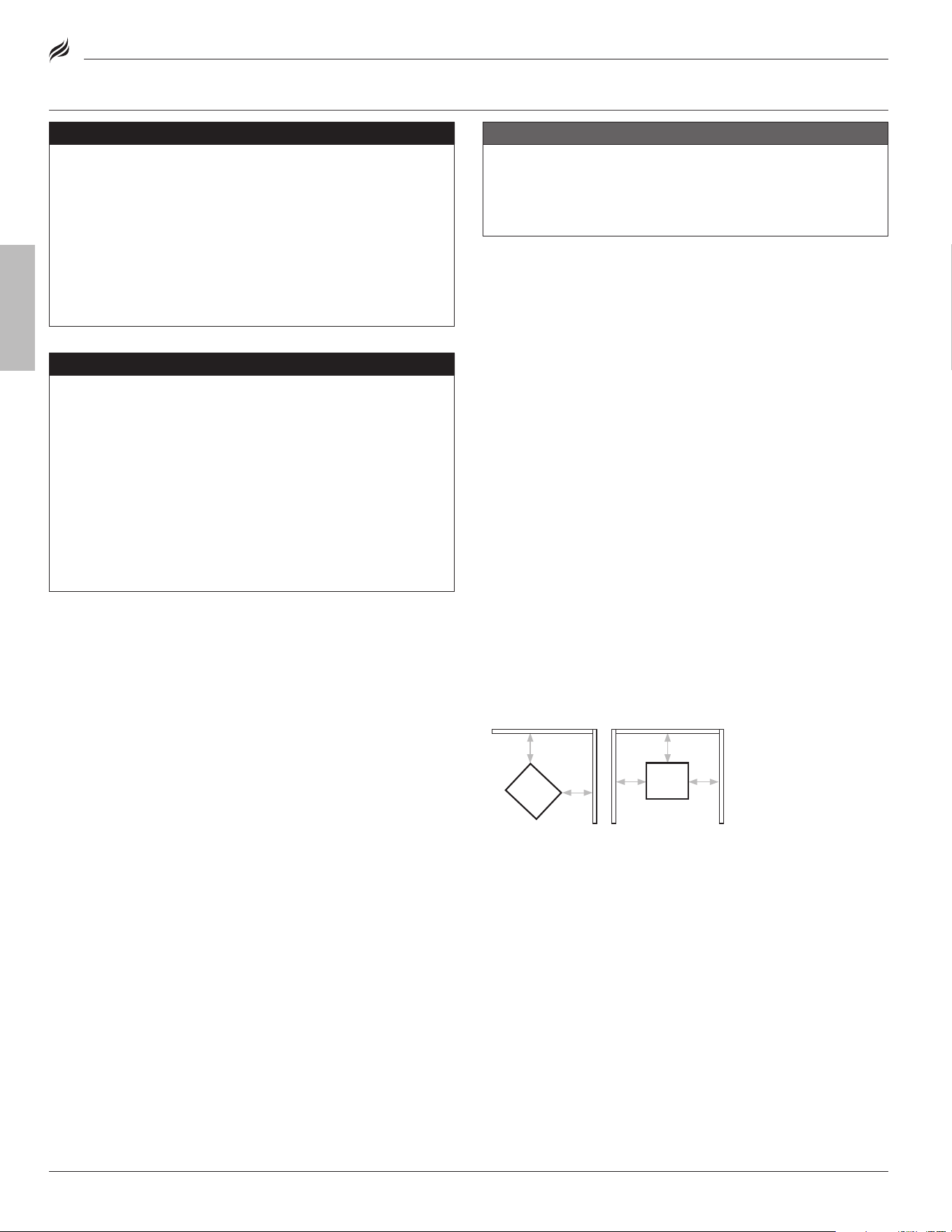
MAINTAIN PROPER CLEARANCES FROM COMBUSTIBLE MATERIAL:
• do NoT use this appliance on or under any apartment or condo-
minium balcony or deck�
• do NoT use this appliance under overhead combustible
construction�
• do NoT obstruct the flow of combustion and ventilation air�
• do NoT operate this appliance any closer than 36 in (1 m) from the
sides and back of the appliance�
A = 36" (1 m)
A = 36" (1 m)
A
A
A
A
A
A
A
A
A
A
WARNING
• do NoT store or use gasoline or other flammable liquids
or vapors in the vicinity of this or any other appliance.
• An lPG cylinder not connected for use shall not be
stored in the vicinity of this or any other appliance.
dANGeR
• NeVeR operate this appliance unattended.
• NeVeR operate this appliance within 10 ft (3.0 m) of any
structure, combustible material or other gas cylinder.
• NeVeR operate this appliance within 25 ft (7.5 m) of any
flammable liquid.
• If a fire should occur, keep away from the appliance and
immediately call your fire department. do NoT attempt
to extinguish an oil or a grease fire with water.
Failure to follow these instructions could result in fire or
property damage, personal injury or death.
INSTALLATION MUST CONFORM WITH LOCAL CODES
In the absence of local codes, installation must conform with:
a. National Fuel Gas Code, ANSI Z223�1/NFPA 54, Storage and Handling
of Liquefied Petroleum Gases, ANSI/NFPA 58; or
b. Natural Gas and Propane Installation Code, CSA B149�1; Propane
Storage and Handling, CSA B149�2; or
c. The Standard for Recreational Vehicles, ANSI A119�2/NFPA 1192; and
Recreational Vehicle Code, CSA Z240 RV Series, as applicable�
dANGeR
If you smell gas:
• Shut off gas to the appliance.
• extinguish any open flame.
• If odor continues, keep away from the appliance
and immediately call your gas supplier or your fire
department.
Failure to follow these instructions could result in fire or
property damage, personal injury or death.
Model: 6825
IMPORTANT SAFETY INFORMATION
02
BLACKSTONEPRODUCTS.COM/SUPPORT
ENGLISH
| OWNER’S MANUALACTIVATE YOUR WARRANTY
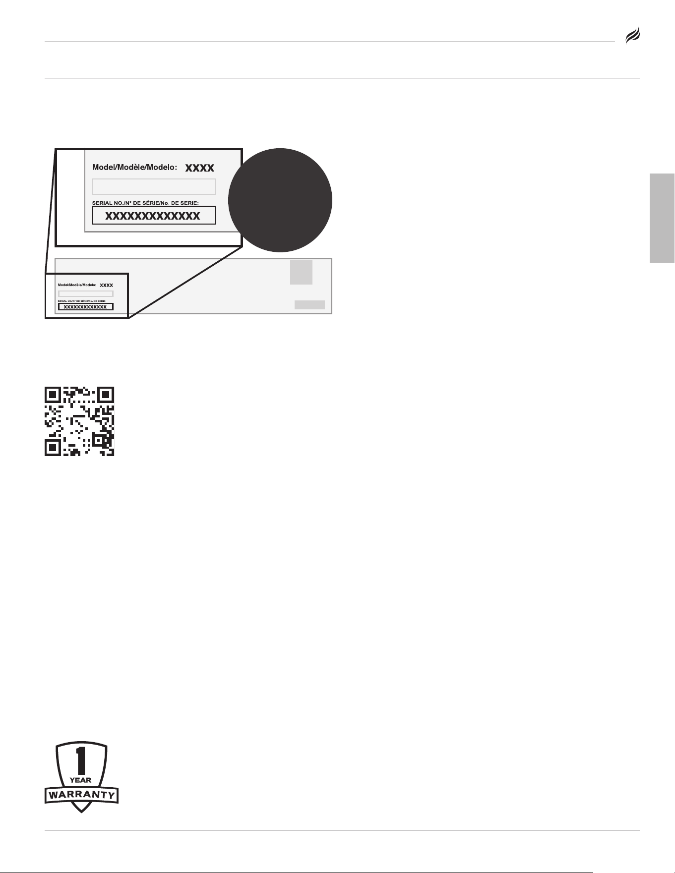
Register your appliance at
BlackstoneProducts.com/register
The North Atlantic Imports llC 1-Year Warranty covers replacement
parts up to one year after the date of purchase�
TO ENABLE THIS WARRANTY, YOU WILL NEED TO PROVIDE:
☞
☞
Your appliance’s Serial Number
The Serial Number can be found on your appliance’s
Manufacturer label�
(The Manufacturer label is a large silver sticker found on the body of your
(The Manufacturer label is a large silver sticker found on the body of your
appliance.)
appliance.)
WARRANTY OVERVIEW
North Atlantic Imports, the manufacturer, will warranty for one year
from purchase all parts, workmanship, and finishes� It will be the
manufacturer’s option as to whether to repair or replace any of the
above items� All warranties are limited to the original purchaser
only� This warranty does not cover any liability on the part of North
Atlantic Imports, its agents or employees, for any indirect or conse-
quential damages for breach of warranty� The purchaser must follow
the manufacturer’s usage instructions�
Under no circumstances is the manufacturer responsible for
damages from the failure to operate the cooking station properly� It is
the responsibility of the purchaser to establish the warranty period
by verifying the original purchase date with original sales receipt�
DETAILED ExPLANATION OF THE WARRANTY
North Atlantic Imports llC warrants to the owner that the product
covered by this agreement is free from defects in material and work-
manship under normal use and service for which it was intended if,
but only if, it has been operated in accordance with North Atlantic
Imports llC instructions exclusively for domestic use, and not for
private or public club, institutional or commercial purposes�
North Atlantic Imports llC’s obligation under this warranty is limited
to replacing or repairing, free of charge, any part or parts that
may prove, to the satisfaction of North Atlantic Imports llC, to be
defective under normal home use and service within the following
stated periods of time from the date of purchase; for one year from
purchase, all parts, finish, and workmanship� Should any failure
to conform to this warranty become apparent during applicable
warranty periods stated above, the original purchaser must notify
North Atlantic Imports llC of breach of warranty within the appli-
cable warranty period�
North Atlantic Imports llC shall upon notice and compliance by the
original purchaser with such instructions, correct such nonconfor-
mity by repair or replacement of the defective part or parts�
Correction in the manner provided above shall constitute a fulfill-
ment of all obligations of North Atlantic Imports llC with respect to
the quality of the product�
North Atlantic Imports llC does not warrant this equipment to meet
the requirement of any safety code of any state, municipality or other
jurisdiction, and the original purchaser assumes all risk and liability
whatsoever resulting from the use thereof, whether used in accor-
dance with North Atlantic Imports llC instructions or otherwise�
This warranty does not cover and is intended to exclude any liability
on the part of North Atlantic its agents, servants or employees
whether under this warranty or implied by law for any indirect or
consequential damages for breach on any warranty� The purchaser
must establish all applicable warranty periods pursuant to this
warranty by verifying the original purchase date by producing the
dated sales receipt� This warranty shall not apply to this product or
any other part thereof which has been subject to accident, negli-
gence, alteration, abuse, or misuse or which has been repaired or
altered without North Atlantic written consent, outside of North
Atlantic Imports llC factory� The full manufacturer warranty is
not valid for griddles purchased from unlicensed, third-party
resellers, purchased at a discount due to missing or damaged
parts, or purchased as a floor model; at the discretion of North
Atlantic Imports�
North Atlantic Imports llC makes no warranty whatsoever in respect
to accessories or parts not supplied with it� This warranty shall
apply only within the boundaries of the United States of America and
Canada� This warranty gives the original purchaser specific rights,
and the original purchaser may also have other rights, which vary
from state to state�
������������������������������������������
��������������������������
���������������������������������
����������������������������������������
��������������������������������������
����������������������������������
���������������������������������������
���������������������������
������������������������������������
��������������������������������������
����������������������������������������
����������������������������������������
��������������������������
������������������������������������������
�����������������������������
����������������������������������
�����������������������������������������
����������������������������������������
������������������������������������������
����������������������������
����������������������������
����������������������������������������������������
�������������������������������������������������
��������������������������������
���������������������������������������
���������������������������������������������������
����������������������������������������������������
������������������������������������������������������
��������������������������������
��������������������������������������������
��������������������������������������������������
�������������������������������������������������
������������������������������������������������������
��������
����������������������������������������������������
����������������
����������������
����������������
����������������
�����������������������������������
����������������
������������������������
��������������������������������
��������������������������������
������������
������������������������������������������
��������������������������
���������������������������������
����������������������������������������
��������������������������������������
����������������������������������
���������������������������������������
���������������������������
������������������������������������
��������������������������������������
����������������������������������������
����������������������������������������
��������������������������
������������������������������������������
�����������������������������
����������������������������������
�����������������������������������������
����������������������������������������
������������������������������������������
����������������������������
����������������������������
����������������������������������������������������
�������������������������������������������������
��������������������������������
���������������������������������������
���������������������������������������������������
����������������������������������������������������
������������������������������������������������������
��������������������������������
��������������������������������������������
��������������������������������������������������
�������������������������������������������������
������������������������������������������������������
��������
����������������������������������������������������
��������
��������
��������
��������
��������
����������������
����������������
����������������
����������������
�����������������������������������
����������������
������������������������
��������������������������������
��������������������������������
������������
☞
FRee
MoBIle-FRIeNdlY
CooKBooK
when you register
Model: 6825
ACTIVATE YOUR WARRANTY
03
ENGLISH
BLACKSTONEPRODUCTS.COM/SUPPORT
OWNER’S MANUAL | ASSEMBLY GUIDE Model: 6825
ASSEMBLY GUIDE
PARTS
QTY
1.1a
Control panel 1
1.1b
Nameplate
1
1.1c
Control knob bezel
1
1.1d
Control knob
1
1.2a
Burner box surround
panel
1
1.2b
Burner connecting
plates
2
1.3a
Burner box bottom
panel
1
PARTS
QTY
1.3b
Burner base panel 1
1.3c
Burner insulation
panel
1
1.4a
Shaft bearing mount
1
1.4b
Shaft bearing sleeve
1
1.5a
oven body surround
panel
1
1.5b
oven door seat
1
1.5c
Thermometer
1
PARTS
QTY
1.5d
oven body bottom
panel
1
1.6a
Upper pizza chamber
1
1.6b
lower pizza
chamber
1
1.6c
Fire bale panel
1
1.7a
Ignitor
1
1.7b
Motor button
1
1.7c
Ignitor heat shield
1
PARTS
QTY
1.8a
Burner 1
1.8b
Burner top column
1
1.9a
Gas line and regu-
lator assembly
1
1.9b
Safety valve thermo-
couple
1
1.9c
Regulator retaining
bracket
1
26.1
Wing screw
1
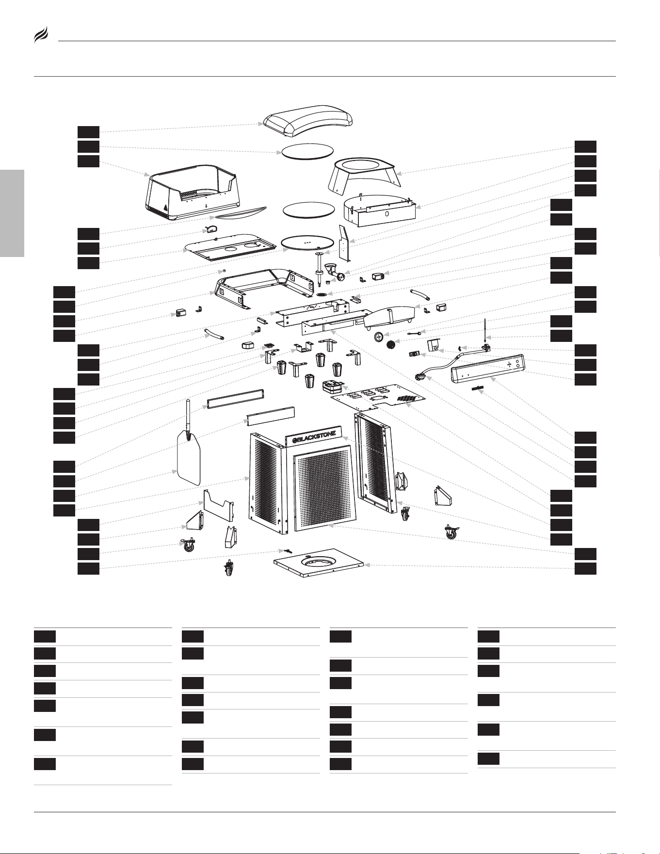
ExPLODED VIEW
PARTS LIST
1.6a
24
10
18
14
22
4
17
25
8
19
1.3b
26
2
16
13
21
20
12
23
3
1.1a
1.2b
81.5c
1.6b
1.1d
1.5a
1.3c
1.7b
1.1b
1.8b
11
1.3a
1.6c
1.2a
1.5d
15
1.7c
1.1c
1.9a
9
1.4a
1.7a
1.5b
1.9c
26.1
1.9b
7
1.4b
6
1.8a
04
BLACKSTONEPRODUCTS.COM/SUPPORT
ENGLISH
| OWNER’S MANUALASSEMBLY GUIDEModel: 6825
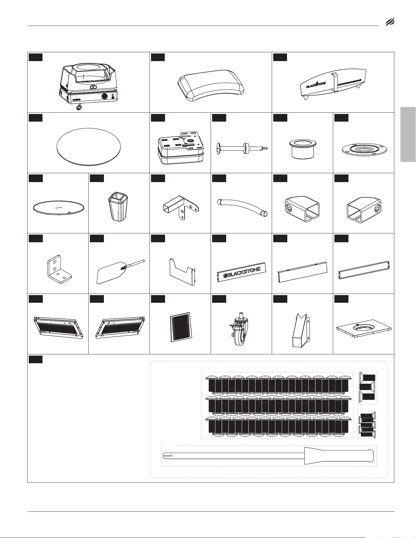
1
oven body (1 piece)
2
oven lid (1 piece)
3
oven door (1 piece)
4
Pizza stones (2 pieces)
5
Motor (1 piece)
6
Rotating shaft
(1 piece)
7
Bronze sleeve
(1 piece)
8
Bearing bracket
(1 piece)
9
Turntable
(1 piece)
10
Feet (4 pieces)
11
legs (4 pieces)
12
Side handles
(2 pieces)
13
Handle stando
(l) (2 pieces)
14
Handle stando
(R) (2 pieces)
15
Fixing plates
(4 pieces)
16
Pizza peel
(1 piece)
17
Pizza peel
holder (1 piece)
18
Front logo panel
(1 piece)
19
orange back-
ground panel (1 piece)
20
Rear cart panel
(1 piece)
21
left cart panel
(1 piece)
22
Right cart panel
(1 piece)
23
Front cart panel
(1 piece)
24
Caster wheels
(4 pieces)
25
Wheel brackets
(4 pieces)
26
Cart base
(1 piece)
27
Hardware pack (1 piece)
a. M6x12 screws (73 pieces)
b. M6x12 countersunk screws (3 pieces)
c. M4x12 screws (5 pieces)
d. Phillips head screwdriver (1 piece)
[a.]
[b.]
[c.]
[d.]
05
ENGLISH
BLACKSTONEPRODUCTS.COM/SUPPORT
OWNER’S MANUAL | ASSEMBLY GUIDE
ASSeMBlY INSTRUCTIoNS
Find a large, clean area to assemble your appliance�
Remove all packing material before assembling�
CAUTIoN
Sharp edges. Wear gloves while assembling.
ELECTRIC REQUIREMENTS:
120V 60Hz
CAUTIoN
Heavy pieces. Two people should assemble this appliance.
NOTICE
Place appliance on a heat-resistant and flame-resistant
surface while in use.
NOTICE
DO NOT leave the hood closed for more than 10 minutes while
cooking.
NOTICE
• DO NOT mix old and new batteries.
• DO NOT mix alkaline, standard (carbon-zinc) or rechargeable
(ni-cad, ni-mh, etc.) batteries.
TOOLS NEEDED:
Phillips head screwdriver &
Adjustable wrench
TOOL NEEDED:
Phillips head screwdriver
TOOL NEEDED:
Adjustable wrench
TOOL NEEDED:
5mm Allen wrench
NOT INCLUDED:
lPG cylinder
Size: 18 x 12 in (45 x 30 cm), 20 lb (9 kg)
Size: 18 x 12 in (45 x 30 cm), 20 lb (9 kg)
lPG cylinder must include collar to
lPG cylinder must include collar to
protect lPG cylinder valve.
protect lPG cylinder valve.
NOT INCLUDED:
17" griddle base
NOT INCLUDED:
22" griddle base
NOT INCLUDED:
AA battery
NOT INCLUDED:
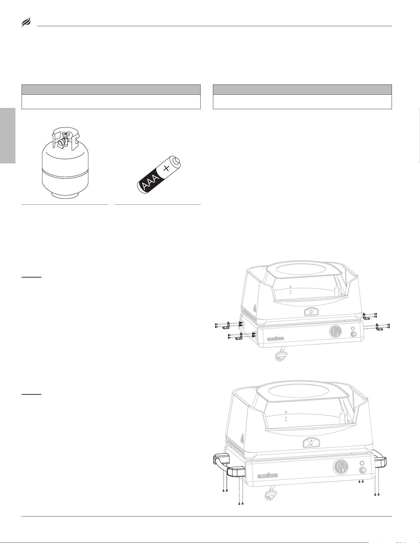
lPG cylinder
Size: 4 x 8 in (10 x 20 cm), 1 lb (453 g)Size: 4 x 8 in (10 x 20 cm), 1 lb (453 g)
NOT INCLUDED:
AAA battery
TOOLS NEEDED:
Phillips head screwdriver &
Adjustable wrench
TOOL NEEDED:
Phillips head screwdriver
TOOL NEEDED:
Adjustable wrench
TOOL NEEDED:
5mm Allen wrench
NOT INCLUDED:
lPG cylinder
Size: 18 x 12 in (45 x 30 cm), 20 lb (9 kg)Size: 18 x 12 in (45 x 30 cm), 20 lb (9 kg)
lPG cylinder must include collar to lPG cylinder must include collar to
protect lPG cylinder valve. protect lPG cylinder valve.
NOT INCLUDED:
17" griddle base
NOT INCLUDED:
22" griddle base
NOT INCLUDED:
AA battery
NOT INCLUDED:
lPG cylinder
Size: 4 x 8 in (10 x 20 cm), 1 lb (453 g)Size: 4 x 8 in (10 x 20 cm), 1 lb (453 g)
NOT INCLUDED:
AAA battery
Model: 6825
STEP 02
Slide one (1) handle stando (l) and one (1) handle stando
(R) onto one (1) side handle�
Use four (4) M6x12 screws [a.] to attach the handle to the fixing
plates on the left side of the burner box�
Repeat with the other handle�
STEP 01
Place the oven base on a smooth flat surface�
Use eight (8) M6x12 screws [a.] to attach four (4) fixing plates to the
burner box�
l
l
R
R
l
l
R
R
[a.] × 8
[a.] × 8
06
BLACKSTONEPRODUCTS.COM/SUPPORT
ENGLISH
| OWNER’S MANUALASSEMBLY GUIDEModel: 6825
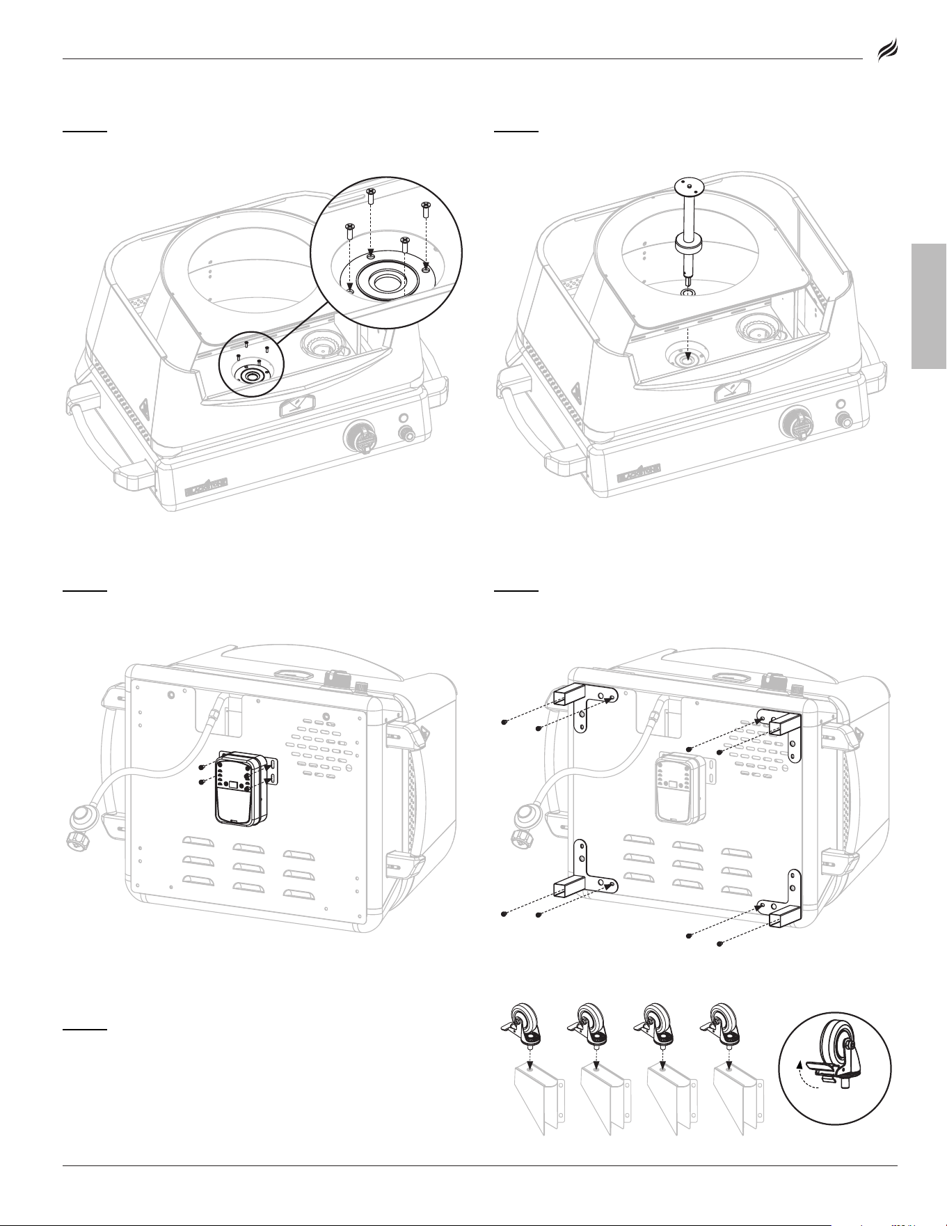
STEP 05
With the help of another person, insert the rotating shaft
into the motor� Use four (4) M6x12 screws [a.] to attach the motor to
the underside of the burner box�
STEP 06
Remove the feet from the legs� Use eight (8) M6x12 screws
[a.]to attach the four (4) legs to the underside of the burner box�
STEP 07
Screw the four (4) caster wheels into the bottom of the four
(4) wheel brackets� (ensure that the wheels are locked�)
STEP 03
Use four (4) countersunk M4x12 screws [c.] to attach the
bearing bracket to the oven floor�
STEP 04
Insert the rotating shaft through the bronze sleeve and into
the bearing bracket�
[a.] × 4
Push to lockPush to lock
[c.] × 4
[a.] × 8
07
ENGLISH
BLACKSTONEPRODUCTS.COM/SUPPORT
OWNER’S MANUAL | ASSEMBLY GUIDE Model: 6825
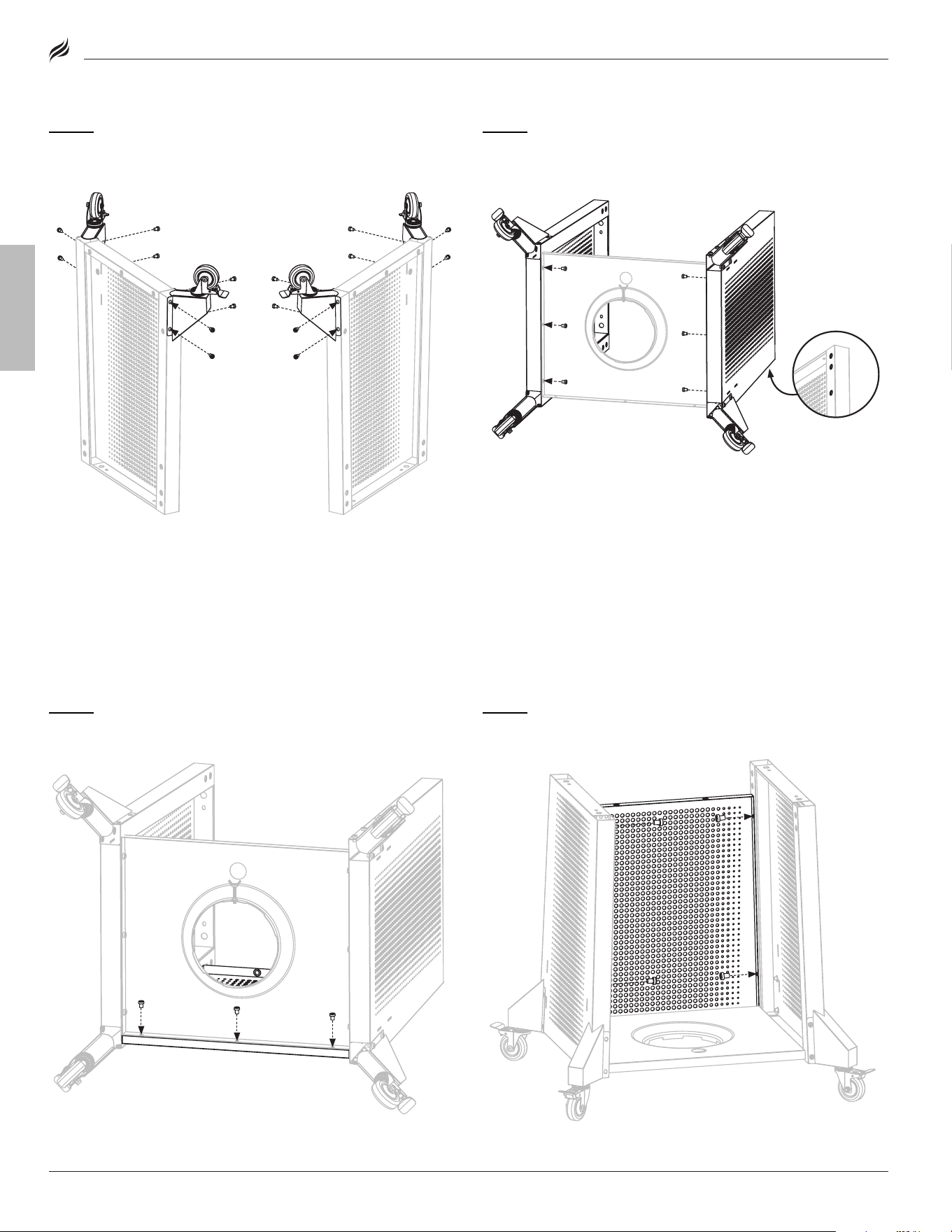
STEP 08
Use eight (8) M6x12 screws [a.] to attach two (2) wheel
assemblies to the left cart panel�
Repeat with the right cart panel�
STEP 09
Use three (3) M6x12 screws [a.] to attach the right cart panel
to the cart base�
Repeat with the left cart panel�
STEP 10
Use three (3) M6x12 screws [a.] to attach the front cart panel
to the cart base�
STEP 11
Use four (4) M6x12 screws [a.] to attach the front cart panel
to the left and right cart panels�
[a.] × 6
Front of cart
Front of cart
[a.] × 16
[a.] × 3
[a.] × 4
08
BLACKSTONEPRODUCTS.COM/SUPPORT
ENGLISH
| OWNER’S MANUALASSEMBLY GUIDEModel: 6825
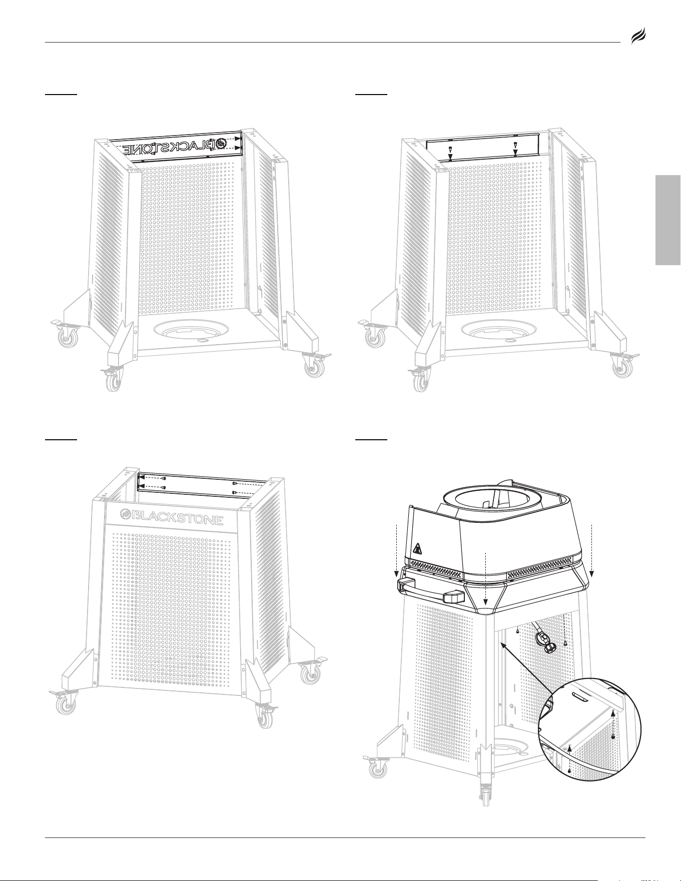
STEP 12
Use four (4) M6x12 screws [a.] to attach the front logo panel
to the left and right cart panels�
STEP 13
Use two (2) M6x12 screws [a.] to attach the orange back-
ground panel to the front logo panel�
STEP 14
Use four (4) M6x12 screws [a.] to attach the rear cart panel to
the left and right cart panels�
STEP 15
With the help of another person, set the oven body on the
cart� Use four (4) M6x12 screws [a.] to secure�
[
a.
] × 4
[a.] × 4
[a.] × 4
[a.] × 2
09
ENGLISH
BLACKSTONEPRODUCTS.COM/SUPPORT
OWNER’S MANUAL | ASSEMBLY GUIDE Model: 6825
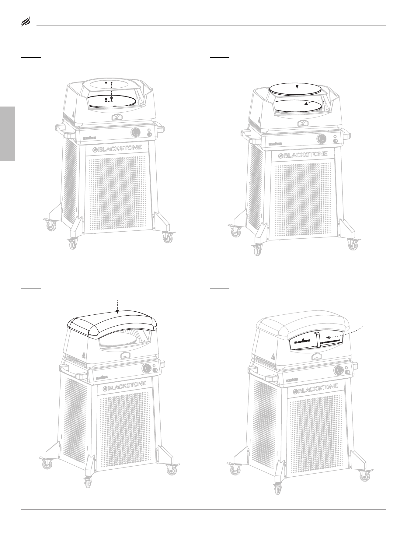
STEP 17
Set one (1) pizza stone on the cast iron turntable� Place one
(1) pizza stone on the upper pizza chamber�
STEP 18
Set the oven lid on the oven body�
STEP 19
Place the oven door over the pizza chamber opening when
the oven is not in use�
STEP 16
Use two (2) M6x12 countersunk screws [b.] to attach the
turntable to the rotating shaft�
[b.] × 2
10
BLACKSTONEPRODUCTS.COM/SUPPORT
ENGLISH
| OWNER’S MANUALASSEMBLY GUIDE
CAUTIoN
NEVER leave oil exposed in the rain. This can lead to severe
burns.
Place the included hardcover on the burner when not in use
or if it begins to rain.
NOTICE
• Maximum weight on the side shelf is 10 lbs (4.5 kg).
• The side shelf may get hot while appliance is in use.
CAUTIoN
Grease build-up on the Flame Tamper can catch fire when
heated.
To prevent damage to the unit and/or injury, clean the top of
the Flame Tamper after each use.
NOTICE
DO NOT sit or stand on the table.
NOTICE
• Maximum weight on the tabletop is 100 lbs (45 kg).
• Maximum weight on the inner shelf is 50 lbs (22.5 kg).
• Maximum weight on the side shelf is 10 lbs (4.5 kg).
CAUTIoN
Handle will get hot while appliance is in use.
DO NOT touch the handle while appliance is hot.
Model: 6825
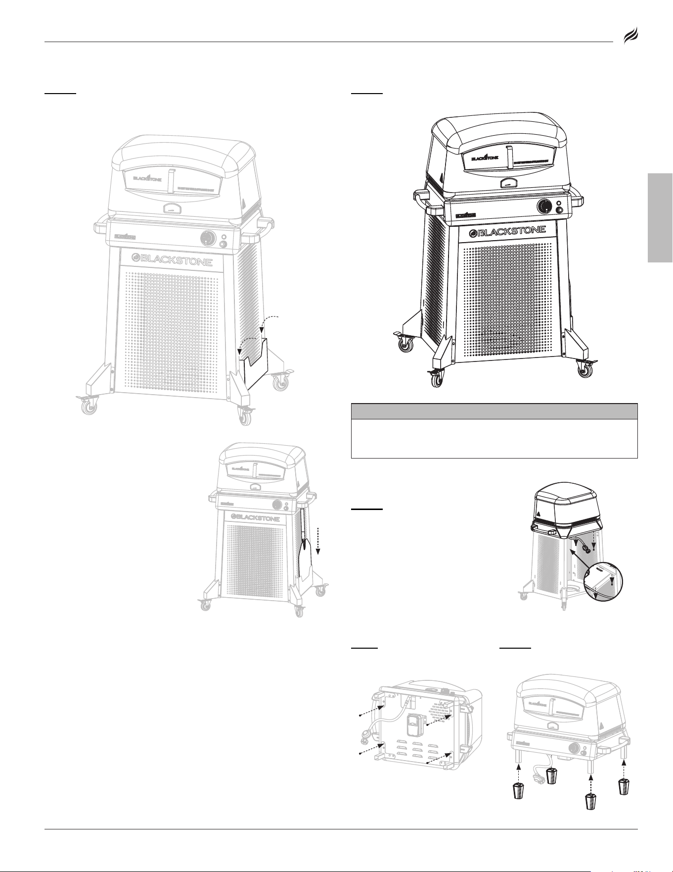
STEP 20
If you are right handed, slide the pizza peel holder into the
slots on the right cart panel� If you are left handed, slide the pizza
peel holder into the left cart panel�
STEP 21
Proceed to USING YOUR BLACKSTONE�
The pizza peel can be kept in
the pizza peel holder when
not in use�
FOR TABLETOP USE:
STEP 01
Remove the four (4)
M6x12 screws that are securing
the oven body to the cart�
STEP 02
Thread the four M6x12
screws back into the oven body�
STEP 03
Slide the four (4) feet
onto the legs�
11
ENGLISH
BLACKSTONEPRODUCTS.COM/SUPPORT
OWNER’S MANUAL | USING YOUR BLACKSTONE
CoNNeCT THe lPG CYlINdeR
20 LB (9 KG)
STEP 01
Turn the control
knobs to oFF�
❶
❶
ensure that the lPG cylinder
is oFF by turning the oPd hand
wheel clockwise to a full stop�
❷
❷
Remove the safety cap from
the Type 1 valve outlet�
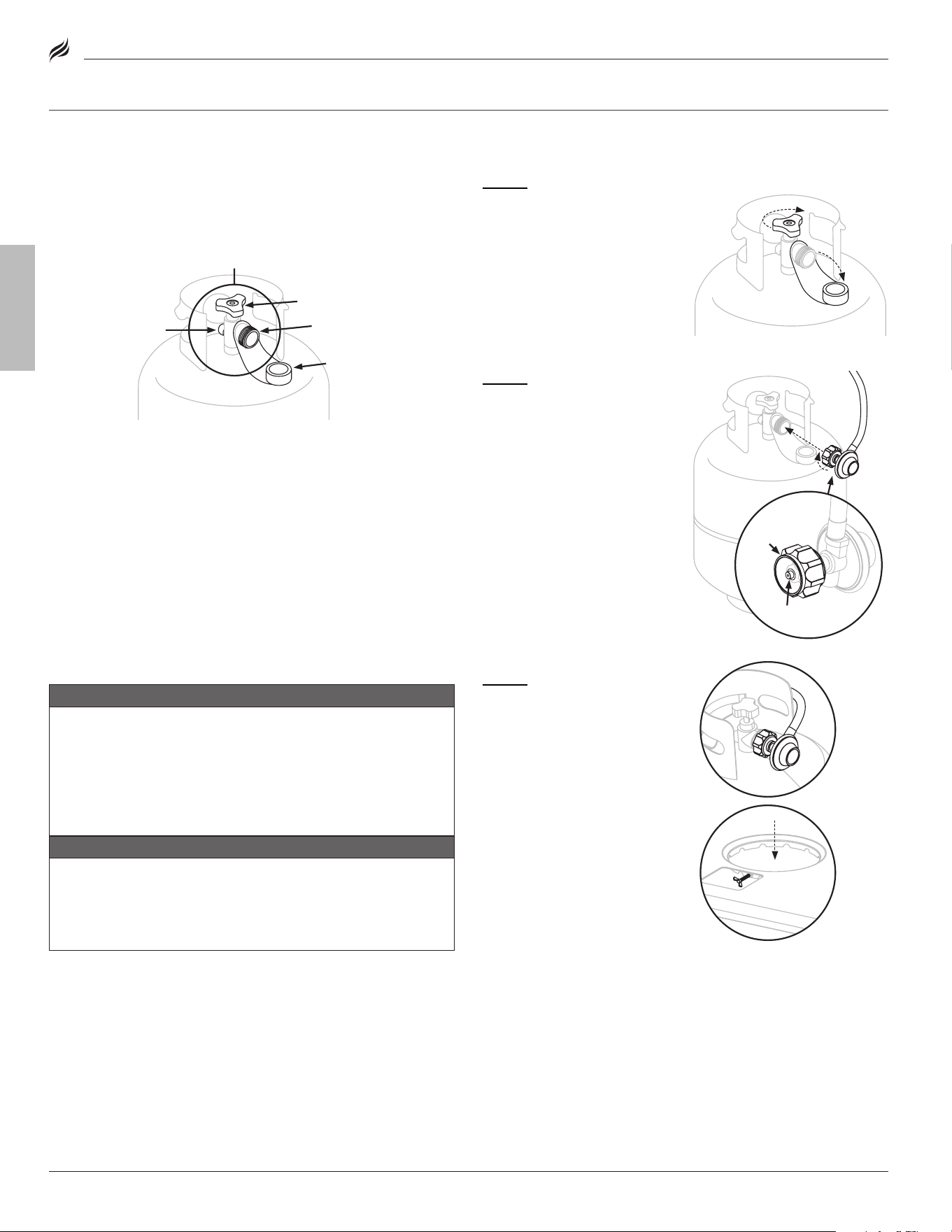
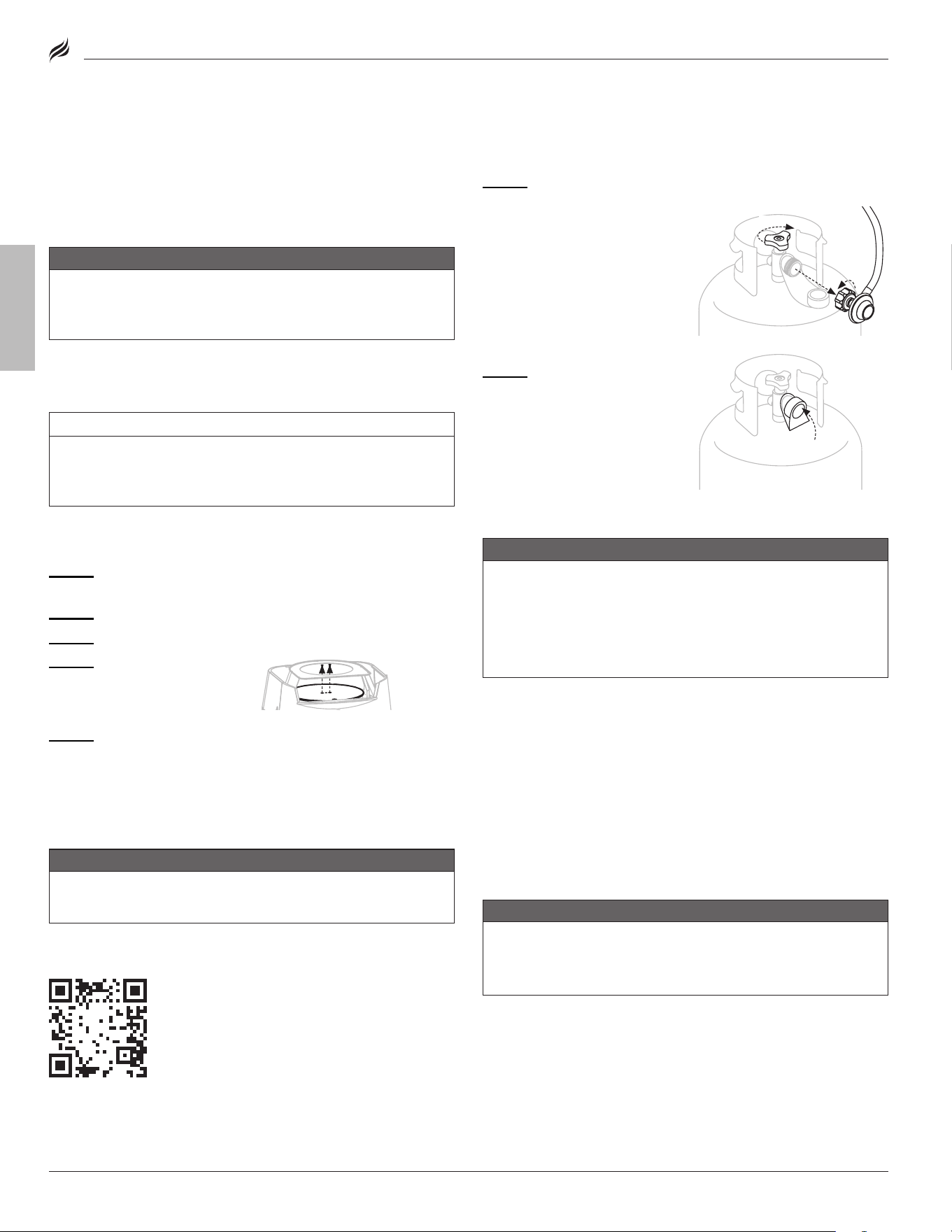
STEP 02
Hold the regulator in a
straight line with the Type 1 valve
outlet so as not to cross thread
the connection�
Center and insert the regu-
lator nipple into the Type 1
valve outlet�
Hand-tighten the coupling nut in
a clockwise direction�
(do NoT use tools to connect�)
If connection cannot be completed,
If connection cannot be completed,
disconnect regulator and repeat this
disconnect regulator and repeat this
step.
step.
THE LPG CYLINDER VALVE MUST HAVE:
• Type 1 valve outlet (thread on the outside)�
• Safety relief valve�
• Ul listed overfill Protection device (oPd)� This oPd safety feature is
identified by a unique triangular hand wheel�
• Safety cap (dust cap)�
LPG CYLINDER REQUIREMENTS
• The lPG supply cylinder to be used must be constructed and
marked in accordance with the specifications for lP gas cylin-
ders, U�S� department of Transportation (doT) or the Standard for
Cylinders, Spheres and Tubes for the Transportation of dangerous
Goods, CAN/CSA-B339�
• only lPG cylinders marked “propane” shall be used�
The lPG cylinder supply system must be arranged for vapor
withdrawal�
•
•
Always keep new lPG cylinders in upright position during use, transit or
Always keep new lPG cylinders in upright position during use, transit or
storage.
storage.
•
•
Always keep the ventilation opening(s) of the cylinder enclosure free and
Always keep the ventilation opening(s) of the cylinder enclosure free and
clear from debris.
clear from debris.
REGULATOR SAFETY
WARNING
Cross threading can occur if you force thread a connection
at an improper angle. This will damage the threads, lead to
propane leaking, and potentially result in a build-up of fuel
that can ignite.
DO NOT cross thread the connection between your LPG
cylinder and regulator.
WARNING
If you can not connect the regulator, DO NOT use the
regulator.
Regulator must be replaced with a Blackstone approved
model by a professionally licensed, authorized dealer.
Use this appliance, as purchased, only with gas and regulator/valve
assembly supplied�
FITTINGS & HOSES
• Annual checking and tightening of metal fittings is recommended�
• Keep the fuel supply hose away from any heated surfaces�
• Before each use, check to see if hoses are cut or worn�
Replace damaged hose before using appliance. (Use only Blackstone approved
Replace damaged hose before using appliance. (Use only Blackstone approved
replacement parts for valve, hose, or regulator. Failure to comply will void the
replacement parts for valve, hose, or regulator. Failure to comply will void the
warranty.)
warranty.)
lPG cylinder valvelPG cylinder valve
Safety relief
Safety relief
valve
valve
oPd hand wheel
oPd hand wheel
Type 1 valve
Type 1 valve
outlet
outlet
Safety cap
Safety cap
❶❶
❷
❷
Coupling nutCoupling nut
Regulator nippleRegulator nipple
STEP 03
Set the lPG cylinder on
the cart base� Tighten the cart
base wing screw to secure it to
the appliance�
Model: 6825
USING YOUR BLACKSTONE
12
BLACKSTONEPRODUCTS.COM/SUPPORT
ENGLISH
| OWNER’S MANUALUSING YOUR BLACKSTONE
LEAK TEST INSTRUCTIONS
NOTICE
DO NOT use household cleaning agents. Damage to gas valve,
hose, and regulator components may result.
Use a clean paintbrush and a 10/90 mild soap and water
solution to perform the leak test.
LEAK TEST: LPG CYLINDER
• leak test new and exchanged lPG cylinders BeFoRe connecting
to griddle�
• do NoT smoke during leak test�
• do NoT use an open flame to check for gas leaks�
• Appliance must be leak tested outdoors in a well-ventilated
area, away from ignition sources such as gas fired or electrical
appliances�
• during leak test, keep appliance away from open flames or sparks�
LEAK TEST: VALVES, HOSE & REGULATOR
STEP 01
Turn the control knobs to oFF�
STEP 02
Connect the regulator to the lPG cylinder�
STEP 03
Completely open the lPG tank by turning the oPd hand
wheel counterclockwise�
• If you hear a rushing sound, turn gas o immediately� There is a
major leak at the connection�
• Immediately close the lPG cylinder by turning the oPd hand wheel
clockwise and re-tighten connections� If leaks cannot be stopped
do NoT TRY To RePAIR�
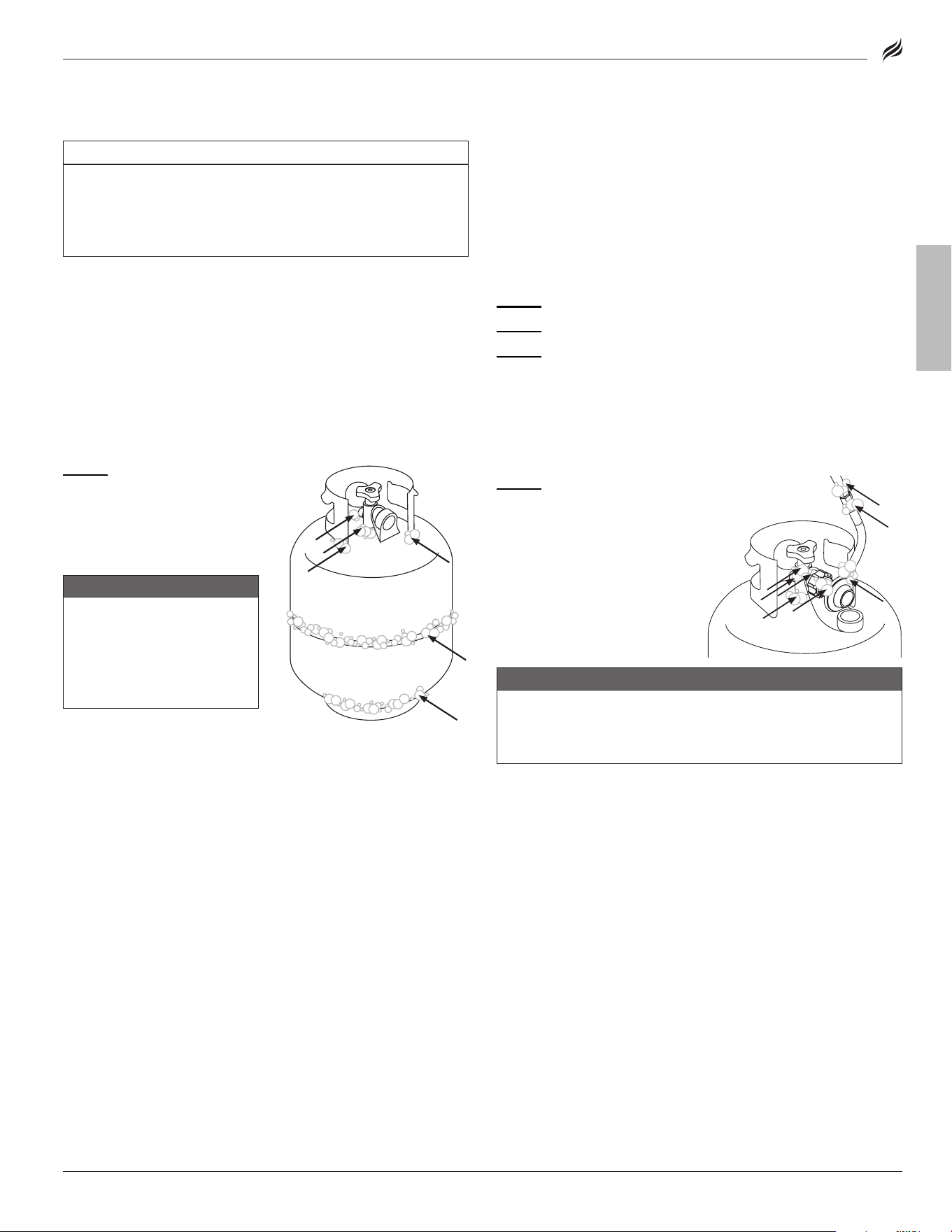
STEP 01
Brush soapy solution
onto joint areas of the lPG
cylinder�
(Indicated by arrows in figure 01.)
(Indicated by arrows in figure 01.)
• leaks are indicated by
growing bubbles�
WARNING
If growing bubbles appear
during leak test, DO NOT use
or move the LPG cylinder.
Immediately contact an LPG
supplier or fire department.
STEP 04
Brush soapy solution
onto joint areas of valves and
regulator�
(Indicated by arrows in figure 02.)
(Indicated by arrows in figure 02.)
• leaks are indicated by
growing bubbles�
• Immediately close the lPG
cylinder by turning the oPd
hand wheel clockwise and
re-tighten connections�
WARNING
If leaks cannot be stopped, DO NOT try to repair.
Regulator must be replaced with a Blackstone approved
model by a professionally licensed, authorized dealer.
figure 02
figure 02
figure 01
figure 01
Model: 6825
13
ENGLISH
BLACKSTONEPRODUCTS.COM/SUPPORT
OWNER’S MANUAL | USING YOUR BLACKSTONE
❸
❸
❷
❷
❶
❶
❹
❹
2. THERMOCOUPLE SAFE-START IGNITION
do NoT use the oven door while oven is on�
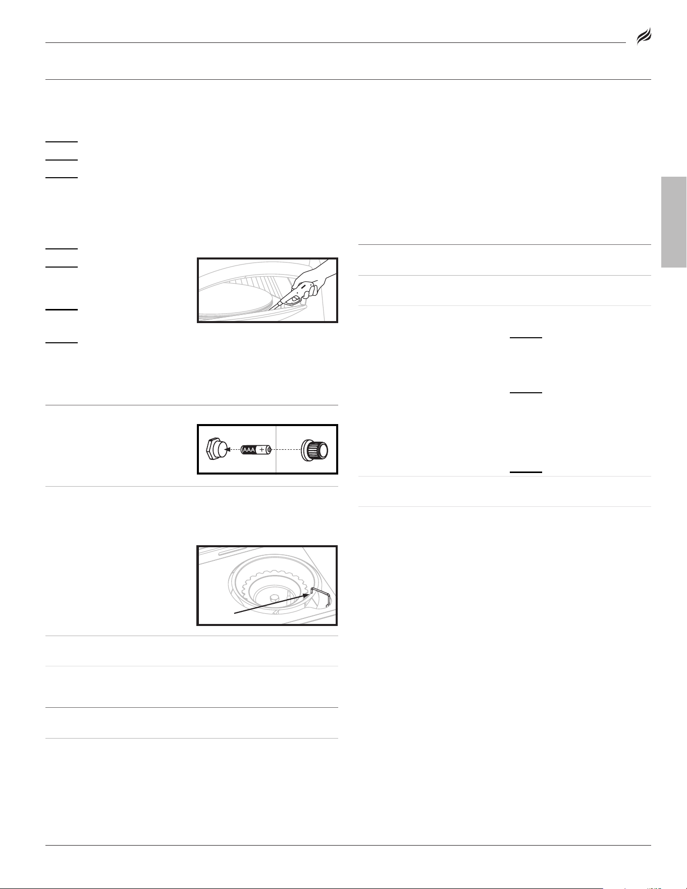
STEP 01
Insert one (1) AAA
battery (not included) under the
battery cap�
Screw the cap into place over the
positive terminal�
STEP 02
❶
❶
Turn the control
knob to oFF�
STEP 03
Turn gas oN at the lPG
cylinder by turning the oPd
hand wheel counterclockwise 1
to 3 turns�
Tighten the red knob on the
regulator clockwise to its
HIGH position�
STEP 04
❷
❷
Turn on the motor�
❸
❸
Push and turn the control knob counter-clockwise to loW� Hold in
for 10~20 seconds until thermocouple allows gas to flow�
once flame is consistant,
❹
❹
adjust to achieve desired
temperature
❺.
❺.
❺
❺
260 - 430° C
430+° C
90 - 260° C
tightentighten
1 to 3 turns1 to 3 turns
Warming Zone
Warming Zone
Cooking Zone
Cooking Zone
Burn off/ Cleaning Zone
Burn off/ Cleaning Zone
❶❶
Push the control knob in to
start gas flowing�
❷❷
Turn the control knob
counter-clockwise to activate
the starter�
❸❸
Adjust the temperature to
desired level�
2. PIEZO-ELECTRIC GRIDDLE IGNITION
do NoT lean over the appliance while lighting�
IGNITIoN INSTRUCTIoNS
1. CHECK VALVES
STEP 01
Turn knob to oFF position�
STEP 02
Push in knob and release� Knob should spring back�
If knobs
If knobs
do NoT
do NoT
spring back, replace valve assembly before using appliance.
spring back, replace valve assembly before using appliance.
STEP 03
Rotate knob to loW then turn back to oFF� Knob should
turn smoothly�
❷❷
❶❶
❸❸
HEALTHY BURNER FLAME
PATTERN
HEALTHY BURNER FLAME
PATTERN
BURNER FLAMES ARE YELLOW
OR IRREGULAR
BURNER FLAMES ARE YELLOW
OR IRREGULAR
3. CHECK BURNER FLAME
Always check burner flame
before use�
STEP 01
light burners and rotate
knobs from HIGH to loW�
STEP 02
look below the cooking
top to view burners� When knob
is at HIGH, flames should be
larger than when knob is at loW�
3. CHECK BURNER FLAME
Always check burner flame
before use�
STEP 01
light burner and rotate
knob from loW to HIGH�
STEP 02
look below the turntable
to view burner� When knob is at
HIGH, flames should be larger
than when knob is at loW�
❶❶
Flickers of yellow color�
❷❷
dark blue color�
❸❸
Vibrant blue�
❶
❶
Flickers of yellow color�
❷
❷
dark blue color�
❸
❸
Vibrant blue�
WARNING
A clogged burner can
lead to a fire beneath the
appliance.
Burner should be removed
and cleaned annually or
whenever heavy build-up
or insects/insect nests are
found.
WARNING
A clogged burner can
lead to a fire beneath the
appliance.
Burner should be removed
and cleaned annually or
whenever heavy build-up
or insects/insect nests are
found.
If there is a sudden drop or low
flame issue, please reference the
Troubleshooting chapter�
If there is a sudden drop or low
flame issue, please reference the
Troubleshooting chapter�
❶❶
❷❷
❸❸
❶
❶
❷
❷
❸
❸
Model: 6825
14
BLACKSTONEPRODUCTS.COM/SUPPORT
ENGLISH
| OWNER’S MANUALUSING YOUR BLACKSTONE
CooKING oN YoUR BlACKSToNe
dANGeR
Flammable items can spontaneously combust if placed near
the appliance. DO NOT place flammable items such as aerosol
containers, oily or greasy towels near the cooking surface.
CAUTIoN
This appliance will be hot during and after use. DO NOT
handle hot parts with unprotected hands. Use long-handled
cooking utensils and oven mitts.
NOTICE
DO NOT store any items within 3 in (8 cm) of the cooking
surface while in use.
IF GREASE OR OTHER HOT MATERIAL DRIPS ONTO VALVE, HOSE OR
REGULATOR:
STEP 01
Turn o gas supply immediately�
STEP 02
determine the cause and correct it�
STEP 03
Clean and inspect valve, hose and regulator�
STEP 04
Perform a leak test� (Please reference the leak Test
Instructions in USING YOUR BLACKSTONE�)
VIDEO RECIPES
Find recipes and cooking tips at:
BlackstoneProducts.com/blogs/recipes
youtube.com/c/BlackstoneGriddles
@blackstoneproducts
STRAWBERRIES AND CREAM
PANCAKES
BreakfastBreakfast
TACOS BORRACHOS
dinnerdinner
OKLAHOMA FRIED ONION
BURGER
lunchlunch
FIRST TIME PIZZA STONE CLEANING
Set your oven to HIGH for 15~20 min to burn o residue�
NOTICE
DO NOT use soap on the cooking stone. This will leave a soap
taste in food.
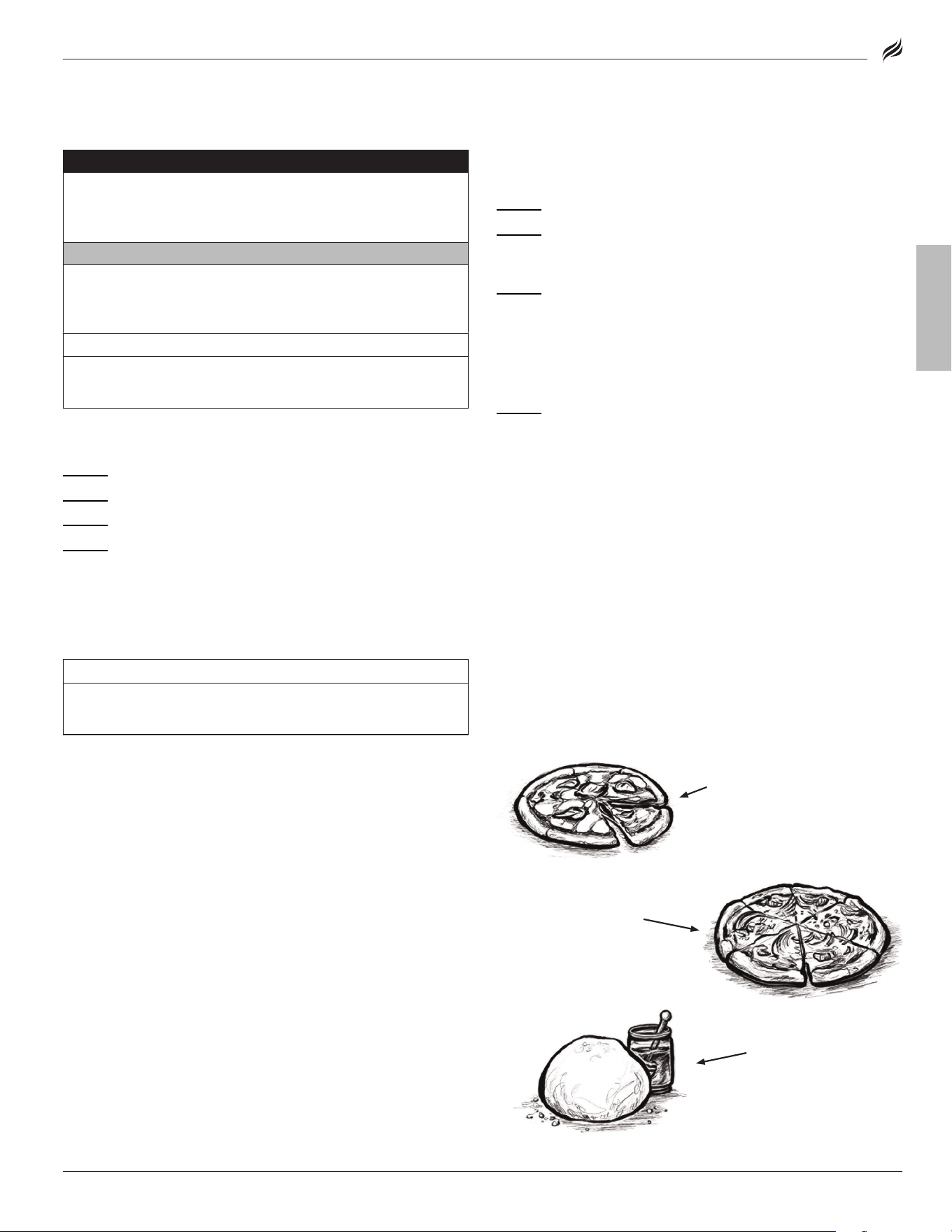
HOW TO USE YOUR PIZZA OVEN
FRESH PIZZA
STEP 01
Preheat oven to 700° F (380° C)�
STEP 02
once the desired temperature is reached, turn the control
knob to adjust throughout the duration of the cook time to achieve
desired result�
STEP 03
Pizza cooking time is about 2-4 minutes depending on the
size and thickness of the dough of the pizza�
a. Thinner foods should be cooked at a higher setting for a shorter
time�
b. Thicker or denser foods should be cooked at a lower setting for a
longer time�
STEP 04
Pull out the pizza when the crust has reached your desired
readiness, or when the edges of the pizza crust are golden-brown�
FROZEN PIZZAS, COOKIES, ETC.
Follow the food manufacturer’s directions on box/ recipe�
(let frozen food thaw a little bit before putting into the hot oven� This
will prevent your pizza stone from cracking�)
CLEANING YOUR OVEN INTERIOR
If the pizza falls o the rotating stone and catches on fire:
STEP 01
Turn oFF the control knob, turn oFF the lPG cylinder, turn
oFF the rotating motor�
STEP 02
Allow the oven to completely cool�
STEP 03
Remove the oven lid, the top stone, and the lower stone�
STEP 05
Use a spatula to scrape and remove debris from cooking
cavity floor� Wipe cooking cavity with a damp cloth� do NoT use
detergent�
If necessary, reference the Troubleshooting chapter for instructions on If necessary, reference the Troubleshooting chapter for instructions on
cleaning the burner.cleaning the burner.
STEP 04
Remove the turntable
by removing the two (2) bolts
that attach the turntable to the
rotating shaft�
CLASSIC MARGHERITA
Pizza
Pizza
NEW YORK STYLE
Pizza dough
Pizza dough
BBQ CHICKEN BACON
Pizza
Pizza
FIRST TIME PIZZA STONE CLEANING
Set your oven to HIGH for 15~20 min to burn o residue�
NOTICE
DO NOT use soap on the cooking stone. This will leave a soap
taste in food.
HOW TO USE YOUR PIZZA OVEN
FRESH PIZZA
STEP 01
Preheat oven to 700° F (380° C)�
STEP 02
once the desired temperature is reached, turn the control
knob to adjust throughout the duration of the cook time to achieve
desired result�
STEP 03
Pizza cooking time is about 2-4 minutes depending on the
size and thickness of the dough of the pizza�
a. Thinner foods should be cooked at a higher setting for a shorter
time�
b. Thicker or denser foods should be cooked at a lower setting for a
longer time�
STEP 04
Pull out the pizza when the crust has reached your desired
readiness, or when the edges of the pizza crust are golden-brown�
FROZEN PIZZAS, COOKIES, ETC.
Follow the food manufacturer’s directions on box/ recipe�
(let frozen food thaw a little bit before putting into the hot oven� This
will prevent your pizza stone from cracking�)
CLEANING YOUR OVEN INTERIOR
If the pizza falls o the rotating stone and catches on fire:
STEP 01
Turn oFF the control knob, turn oFF the lPG cylinder, turn
oFF the rotating motor�
STEP 02
Allow the oven to completely cool�
STEP 03
Remove the oven lid, the top stone, and the lower stone�
STEP 05
Use a spatula to scrape and remove debris from cooking
cavity floor� Wipe cooking cavity with a damp cloth� do NoT use
detergent�
If necessary, reference the Troubleshooting chapter for instructions on If necessary, reference the Troubleshooting chapter for instructions on
cleaning the burner.cleaning the burner.
STEP 04
Remove the turntable
by removing the two (2) bolts
that attach the turntable to the
rotating shaft�
CLASSIC MARGHERITA
PizzaPizza
NEW YORK STYLE
Pizza doughPizza dough
BBQ CHICKEN BACON
PizzaPizza
Model: 6825
15
ENGLISH
BLACKSTONEPRODUCTS.COM/SUPPORT
OWNER’S MANUAL | USING YOUR BLACKSTONE
APPLIANCE STORAGE
WARNING
DO NOT move the appliance when in use. Allow the appliance
to cool to 115°F (45°C) before moving or storing.
COVER FIT GUIDE
Always cover your appliance when stored outdoors�
To find a cover that will fit your appliance, visit
BlackstoneProducts.com/support�
CleANING YoUR APPlIANCe
Clean your appliance after each use, after it is cool to the touch�
• do NoT use abrasive pad on areas with graphics�
• If a bristle brush is used to clean any of the cooking surfaces,
ensure no loose bristles remain on cooking surfaces prior
to cooking�
WARNING
Grease build up can cause a fire. Clean any part of the
appliance that gets hot and experiences grease build up after
each use.
PLASTIC PARTS & PAINTED SURFACES:
Wash with warm soapy water and wipe dry with a non-abra-
sive cloth�
NOTICE
DO NOT use Citrisol, abrasive cleaners, or a concentrated
cleaner on plastic parts. This may result in damage to and
failure of parts.
PULL OUT MOUNTING / STORAGE SYSTEMS:
dANGeR
DO NOT put appliance in storage or travel mode immediately
after use. Allow appliance to cool to touch before moving
or storing. Failure to do so could result in fire resulting in
property damage, personal injury, or death.
This model is suitable for use in an RV when installed in a manner
similar to the slide out tray as shown�
The minimum load specification for the slide out tray when fully extended and The minimum load specification for the slide out tray when fully extended and
in the locked position is 100 lbs. (45.5 Kg.) in the locked position is 100 lbs. (45.5 Kg.)
dISCoNNeCT THe lPG CYlINdeR
20 LB (9 KG)
STEP 01
ensure that the control knobs are turned to oFF�
❶
❶
ensure that the lPG cylinder
is oFF by turning the oPd hand
wheel clockwise to a full stop�
❷
❷
Turn the coupling nut count-
er-clockwise by hand to remove
the regulator� (do NoT use tools
to disconnect�)
STEP 02
Place safety cap on lPG
cylinder valve outlet whenever
cylinder is not in use�
only install the type of safety cap on
only install the type of safety cap on
cylinder valve outlet that is provided
cylinder valve outlet that is provided
with the cylinder valve. other types of
with the cylinder valve. other types of
caps or plugs may result in leakage of
caps or plugs may result in leakage of
propane.
propane.
STORING LPG CYLINDERS
WARNING
• DO NOT store a spare LPG cylinder under or near this
appliance.
• DO NOT fill an LPG cylinder beyond 80% full.
If the information above is not followed exactly, a fire causing
death or serious injury may occur.
• The lPG cylinder must be turned oFF when the appliance is
not in use�
• lPG cylinders must be stored outdoors and out of the reach
of children�
• do NoT store an lPG cylinder inside a building, garage, or any other
enclosed area�
FILLING & ExCHANGE
• Use only those reputable exchange companies that inspect, preci-
sion fill, test and certify their cylinders� lPG dealer must purge new
cylinder before filling�
• Volume of propane in cylinder will vary by temperature�
WARNING
A frosty regulator indicates gas overfill.
Immediately close LPG cylinder valve and call local LPG
dealer for assistance.
• do NoT release liquid petroleum gas (lPG) into the atmosphere�
• To remove gas from lPG cylinder, contact a certified lPG dealer or
local fire department for assistance�
• exchange cylinder only for an oPd safety feature-equipped
cylinder�
Your retailer can help you match a replacement lPG cylinder to your appliance.
Your retailer can help you match a replacement lPG cylinder to your appliance.
❶❶
❷
❷
FIRST TIME PIZZA STONE CLEANING
Set your oven to HIGH for 15~20 min to burn o residue�
NOTICE
DO NOT use soap on the cooking stone. This will leave a soap
taste in food.
HOW TO USE YOUR PIZZA OVEN
FRESH PIZZA
STEP 01
Preheat oven to 700° F (380° C)�
STEP 02
once the desired temperature is reached, turn the control
knob to adjust throughout the duration of the cook time to achieve
desired result�
STEP 03
Pizza cooking time is about 2-4 minutes depending on the
size and thickness of the dough of the pizza�
a. Thinner foods should be cooked at a higher setting for a shorter
time�
b. Thicker or denser foods should be cooked at a lower setting for a
longer time�
STEP 04
Pull out the pizza when the crust has reached your desired
readiness, or when the edges of the pizza crust are golden-brown�
FROZEN PIZZAS, COOKIES, ETC.
Follow the food manufacturer’s directions on box/ recipe�
(let frozen food thaw a little bit before putting into the hot oven� This
will prevent your pizza stone from cracking�)
CLEANING YOUR OVEN INTERIOR
If the pizza falls o the rotating stone and catches on fire:
STEP 01
Turn oFF the control knob, turn oFF the lPG cylinder, turn
oFF the rotating motor�
STEP 02
Allow the oven to completely cool�
STEP 03
Remove the oven lid, the top stone, and the lower stone�
STEP 05
Use a spatula to scrape and remove debris from cooking
cavity floor� Wipe cooking cavity with a damp cloth� do NoT use
detergent�
If necessary, reference the Troubleshooting chapter for instructions on
If necessary, reference the Troubleshooting chapter for instructions on
cleaning the burner.
cleaning the burner.
STEP 04
Remove the turntable
by removing the two (2) bolts
that attach the turntable to the
rotating shaft�
CLASSIC MARGHERITA
PizzaPizza
NEW YORK STYLE
Pizza doughPizza dough
BBQ CHICKEN BACON
PizzaPizza
Model: 6825
16
BLACKSTONEPRODUCTS.COM/SUPPORT
ENGLISH
| OWNER’S MANUALTROUBLESHOOTING
POSSIBLE CAUSES SOLUTION
Something is blocking the
venturi in the burner�
Clean the burner assembly to
remove the obstruction�
POSSIBLE CAUSES SOLUTION
obstructions in the burner, gas
jets, or fuel rail�
Clean the burner, jets, and gas
hose�
lPG cylinder is empty or low�
Refill or replace the lPG
cylinder�
The regulator’s flow limiting
device was triggered�
Reset the safety system:
STEP 01
Turn oFF the appliance,
close the lPG cylinder valve, and
disconnect the regulator from
the lPG cylinder�
STEP 02
Wait five minutes to
allow the pressure to dissipate,
then reconnect the regulator
to the lPG cylinder and slowly
open the oPd hand wheel one
half turn�
STEP 03
Ignite your appliance�
Regulator stuck in safety
position�
Contact customer service for
replacement parts�
GAS FLOW TROUBLESHOOTING
A FLAME IS COMING OUT OF THE AIR GATE:
BURNER FLAMES ARE YELLOW OR IRREGULAR:
• Appliance will not achieve a high heat or heats unevenly�
• Burner flames start strong, then immediately drop to low even
when burner is set to high position�
• Flame height drops when a second burner is lit�
• Flames do NoT extend the full length of the burner, or only run on
one side of the burner�
• Burner flames are inconsistent�
IGNITION TROUBLESHOOTING
BURNER WILL NOT IGNITE:
If ignition does not occur in 5 seconds:
STEP 01
Turn the burner control knob oFF�
STEP 02
Wait 5 minutes�
STEP 03
Repeat the lighting procedure�
If this does not work, to determine the cause, please try to ignite your appli-If this does not work, to determine the cause, please try to ignite your appli-
ance with a match. ance with a match.
IGNITION TROUBLESHOOTING
BURNER WILL NOT IGNITE:
If ignition does not occur in 5 seconds:
STEP 01
Turn the burner control knob oFF�
STEP 02
Wait 5 minutes�
STEP 03
Repeat the lighting procedure�
If this does not work, to determine the cause, please try to ignite your appli-
If this does not work, to determine the cause, please try to ignite your appli-
ance with a match.
ance with a match.
MATCH LIGHTING INSTRUCTIONS
Before beginning, check for gas leaks. open hood (if applicable).Before beginning, check for gas leaks. open hood (if applicable).
STEP 01
Turn control knob to oFF position�
MATCH LIGHTING INSTRUCTIONS
Before beginning, check for gas leaks.
Before beginning, check for gas leaks.
STEP 01
Turn control knob to oFF position�
STEP 04
Push in and turn the control knob to start gas flowing�
ensure burner lights and stays lit�
STEP 04
Push in and turn the control knob to start gas flowing�
ensure burner lights and stays lit�
STEP 02
light a match (or long
lighter) no shorter than 11
inches long�
STEP 03
Place the flame next to
the burner�
STEP 02
light a match (or long
lighter) no shorter than 11
inches long�
STEP 03
Place the flame next to
the burner�
IF YOU CAN IGNITE YOUR APPLIANCE WITH A MATCH:
POSSIBLE CAUSES SOLUTION
dead / improperly installed
battery�
Replace with new battery�
Ignitor wire misaligned�
ensure that the ignitor needle
is positioned 3-7mm away from
the burner, and aligned with the
burner holes�
damage to the ignition system�
Contact customer service for
replacement parts�
IF YOU CAN NOT IGNITE YOUR APPLIANCE WITH A MATCH:
POSSIBLE CAUSES SOLUTION
Burner tubes are not receiving
fuel�
Clean the burner assembly to
remove the obstruction�
IF YOU CAN IGNITE YOUR APPLIANCE WITH A MATCH:
POSSIBLE CAUSES SOLUTION
dead / improperly installed
battery�
Replace with new battery�
Ignitor wire misaligned�
ensure that the ignitor needle
is positioned 3-7mm away from
the burner, and aligned with the
burner holes�
damage to the ignition system� Contact customer service for
replacement parts�
IF YOU CAN NOT IGNITE YOUR APPLIANCE WITH A MATCH:
POSSIBLE CAUSES SOLUTION
Burner tubes are not receiving
fuel�
Clean the burner assembly to
remove the obstruction�
3-7mm3-7mm
3-7mm
3-7mm
Model: 6825
TROUBLESHOOTING
17
ENGLISH
BLACKSTONEPRODUCTS.COM/SUPPORT
OWNER’S MANUAL | TROUBLESHOOTING
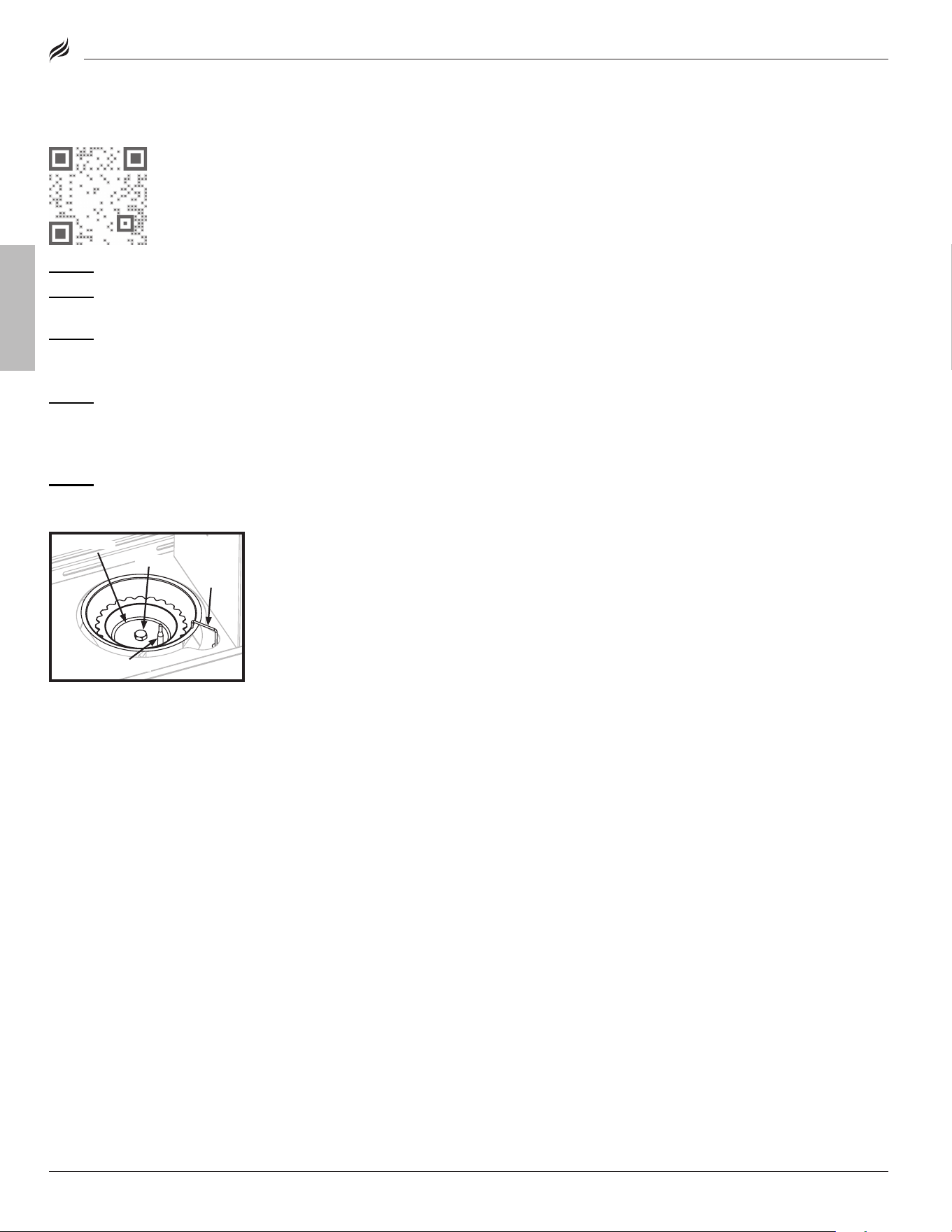
STEP 01
Remove the turntable�
STEP 02
Use compressed air to blow out the burner scallops� (Wear
eye protection)
STEP 03
Remove the hex nut and burner cap�
Note: do NoT disturb the ignitor needle or thermocouple
while cleaning�
STEP 04
Clean the inside of the burner:
• Run a narrow bottle brush through the burner several times� (do
NoT use wire brushes)
• Use compressed air to blow out the burner� (Wear eye protection)
STEP 05
Replace burner cap and hex nut�
If problems persist, contact customer service�
CLEANING THE BURNER ASSEMBLY
VIDEO TUTORIAL
Pizza oven Troubleshooting
hex nut
hex nut
burner cap
burner cap
ignitor
ignitor
needle
needle
thermocouple
thermocouple
CUSTOMER SERVICE
Visit us online at BlackstoneProducts.com/support
for assistance concerning appliance use, replacement parts, or
your warranty�
CUSTOMER SERVICE HOURS:
Monday – Friday
7:00 am – 5:00 pm (MST)
Model: 6825
18

BLACKSTONEPRODUCTS.COM/SUPPORT
ENGLISH
| OWNER’S MANUAL
This page intentionally left blank
Model: 6825
19

ENGLISH
BLACKSTONEPRODUCTS.COM/SUPPORT
This product may be covered by one or more issued U�S� and/or
international patents and may include patent applications pending�
For more information, please visit: BlackstoneProducts�com/patents
dISTRIBUTed BY NoRTH ATlANTIC IMPoRTS, llC 1073 W 1700 N loGAN, UT 84321 USA | BlACKSToNe IS A ReGISTeRed TRAdeMARK oF NoRTH ATlANTIC IMPoRTS, llC
©2022 NoRTH ATlANTIC IMPoRTS� All RIGHTS ReSeRVed�
20