
34
45
6
44
38b
39
40
41
38a
43c
42
43a
43d
43b
38a
38b
38
43a 43b
43c 43d
43
39 40
41
52
30 (2x)
31b
1 (1x)
37 (1x)
35 (2x)
1 (2x)
32b
29
28 (2x)
27 (2x)
6 44
45
56
48
33
26 25
8
9
10
8
9
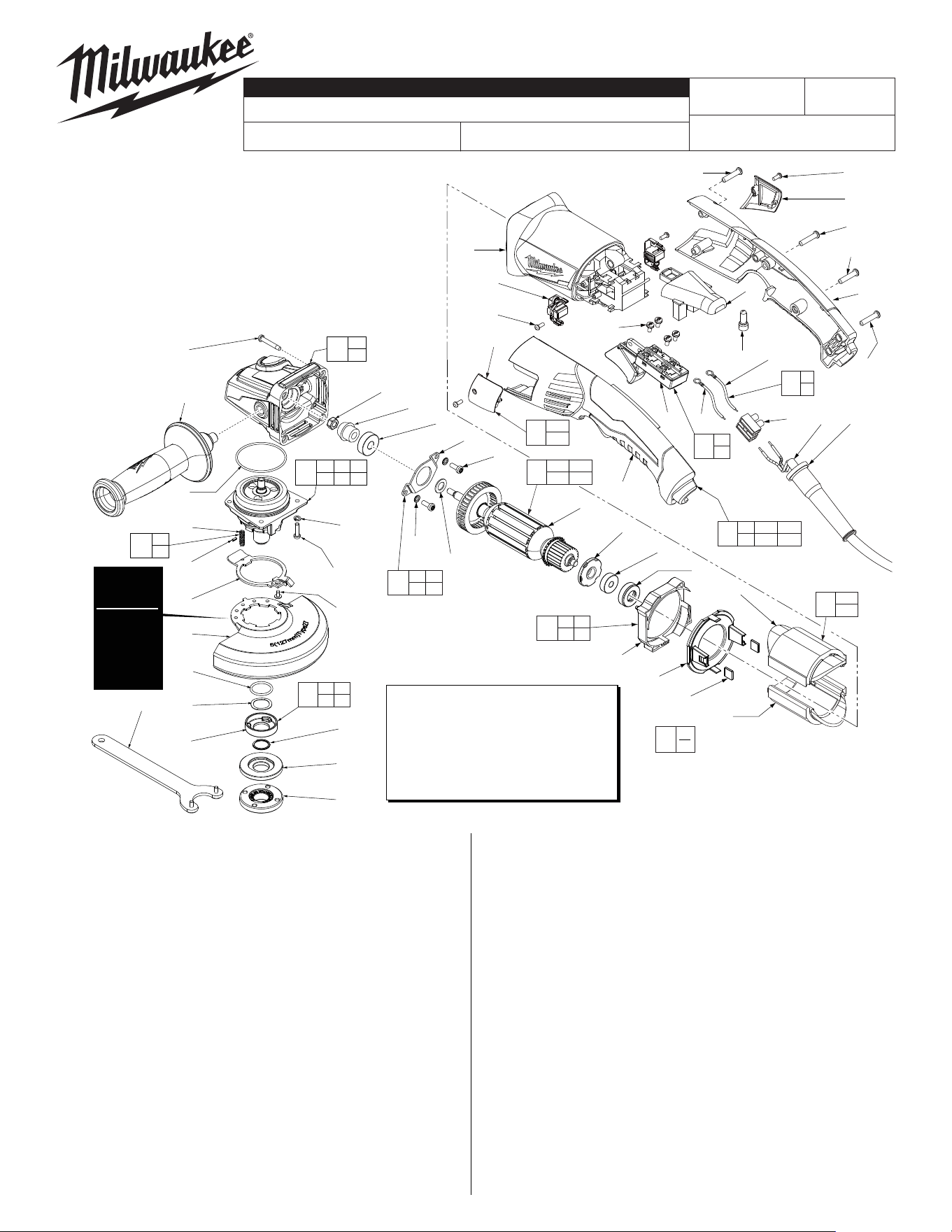
EXAMPLE:
Component Parts (Small #)
Are Included When Ordering
The Assembly (Large #).
0
00
47
46
3g
15 16
17 18
50
5b
5c
65
3
1
(4x)
2
4
5c
5b
5d
13
15
16
17
22
6
(4x)
7(4x)
5e
18
19
21
4 5b 5c
5d 5e 46
5
3g
Type 27
Guard is
Std. Equip.
Optional
Type 1
Guard
available.
Order No.
43-54-1230.
*LUBRICATION NOTE:
When servicing the Gear Case Assembly,
90-95% of the old grease must be re-
moved prior to new grease being added.
FIG. LUBRICATION*
5 Type "Y" Grease, No. 49-08-5270,
Must Be Applied To All Gear Teeth.
24 (4x)
23
31a
31a
31b
31
32a
1 32a 32b
35 37
32
23
24
57
FIG. PART NO. DESCRIPTION OF PART NO. REQ.
35 05-88-1255 M4 x 22mm Pan Hd. ST T-20 (2)
37 06-82-1020 M4 x 14mm Pan Hd. ST T-20 (1)
38 18-07-0310 Field Assembly (1)
38a --------------- Field Halve (1)
38b --------------- Field Halve (1)
39 42-28-0085 Rubber Block (2)
40 --------------- BafeFoot (1)
41 --------------- Bafe (1)
42 42-96-0016 Rubber Bearing Cap (1)
43 16-10-0845 ArmatureAssembly (1)
43a 02-04-2110 Ball Bearing (1)
43b --------------- Armature (1)
43c 45-88-0406 Washer (1)
43d --------------- MagneticDisc (1)
44 05-78-0105 M4x10mmPanHd.Tapt.ScrewT-20 (2)
45 44-86-0155 BearingRetainer (1)
46 --------------- Pinion (1)
47 05-55-0620 M5HexNut (1)
48 22-56-0150 CloseEndConnector (1)
50 14-46-6105 FlangewithRampsAssembly (1)
52 42-14-0515 BafeAssembly (1)
56 44-86-0145 BearingRetainingPlateAssembly (1)
57 14-78-0525 TriggerSwitchAssembly (1)
65 14-46-0241 Spring/PinKit (1)
12-20-1560 ServiceNameplate(NotShown) (1)
10-20-2225 Bi-LingualWarningLabel(NotShown) (1)
FIG. PART NO. DESCRIPTION OF PART NO. REQ.
1 05-88-1650 M4x25mmPanHd.STScrewT-20 (7)
2 42-62-0125 Side Handle Assembly (1)
3 14-30-1156 Gearcase Assembly (1)
3g 02-04-0620 Ball Bearing (1)
4 34-40-0560 O-Ring (1)
5 14-73-0470 Spindle Hub Assembly (1)
5b --------------- SteelPin (1)
5c --------------- Spring (1)
5d 44-20-0155 Guard Locking Tang (1)
5e 05-81-0020 M3x5mmPanHd.STT-8Screw (1)
FIG. PART NO. DESCRIPTION OF PART NO. REQ.
6 05-90-0225 Spring Washer (6)
7 05-78-5316 M4x14mmPanHd.Tapt.ScrewT-20 (4)
8 --------------- Leadwire-Black (1)
9 --------------- Leadwire-White (1)
10 23-94-0345 LeadwireAssy.Kit (1)
13 43-54-1220 5"Type27Guard(StandardEquip.) (1)
13 43-54-1230 5"Type1Guard(Optional,NotShown) (1)
15 --------------- O-Ring (1)
16 --------------- Wavey Spring (1)
17 --------------- FlangewithRamps (1)
18 --------------- RetainingRing (1)
19 43-34-0935 InnerDiscFlange (1)
21 44-40-0035 OuterFlangeNut (1)
22 49-96-7215 Spanner Wrench (1)
23 23-66-2685 TriggerSwitch (1)
24 05-78-0305 M3.5x7mmPanHd.Phil.SwitchScr. (4)
25 44-76-0095 CordProtector (1)
26 22-64-3425 PowerCord (1)
27 05-88-0030 M3x8.5mmPanHd.STScrewT-10 (2)
28 22-18-2250 CarbonBrushAssembly(Setof2) (1)
29 31-50-2140 MotorHousing (1)
30 06-82-2395 M2.6x10mmPanHd.STScrewT-9 (2)
31 31-15-1010 BrushCoverAssembly(Setof2) (1)
31a --------------- BrushCover-Left (1)
31b --------------- BrushCover-Right (1)
32 31-44-0715 RearHandleSet (1)
32a --------------- HandleHalve-Left (1)
32b --------------- HandleHalve-Right (1)
33 22-56-0470 TerminalConnectorBlock (1)
34 22-09-1850 PCB Assembly (1)
MILWAUKEE TOOL ● www.milwaukeetool.com
13135W.LisbonRoad,Brookeld,WI53005
Drwg.2
6124-31
54-38-2192
D01C
5" HP RAT-TAIL ANGLE GRINDER
REVISEDBULLETIN
DATE
Jan. 2017
SERVICE PARTS LIST
BULLETIN NO.
WIRINGINSTRUCTION
CAT. NO.
SPECIFY CATALOG NO. AND SERIAL NO. WHEN ORDERING PARTS
STARTING
SERIALNUMBER
See Reverse Side
54-38-2191
= Part number change
from previous service
partslist.
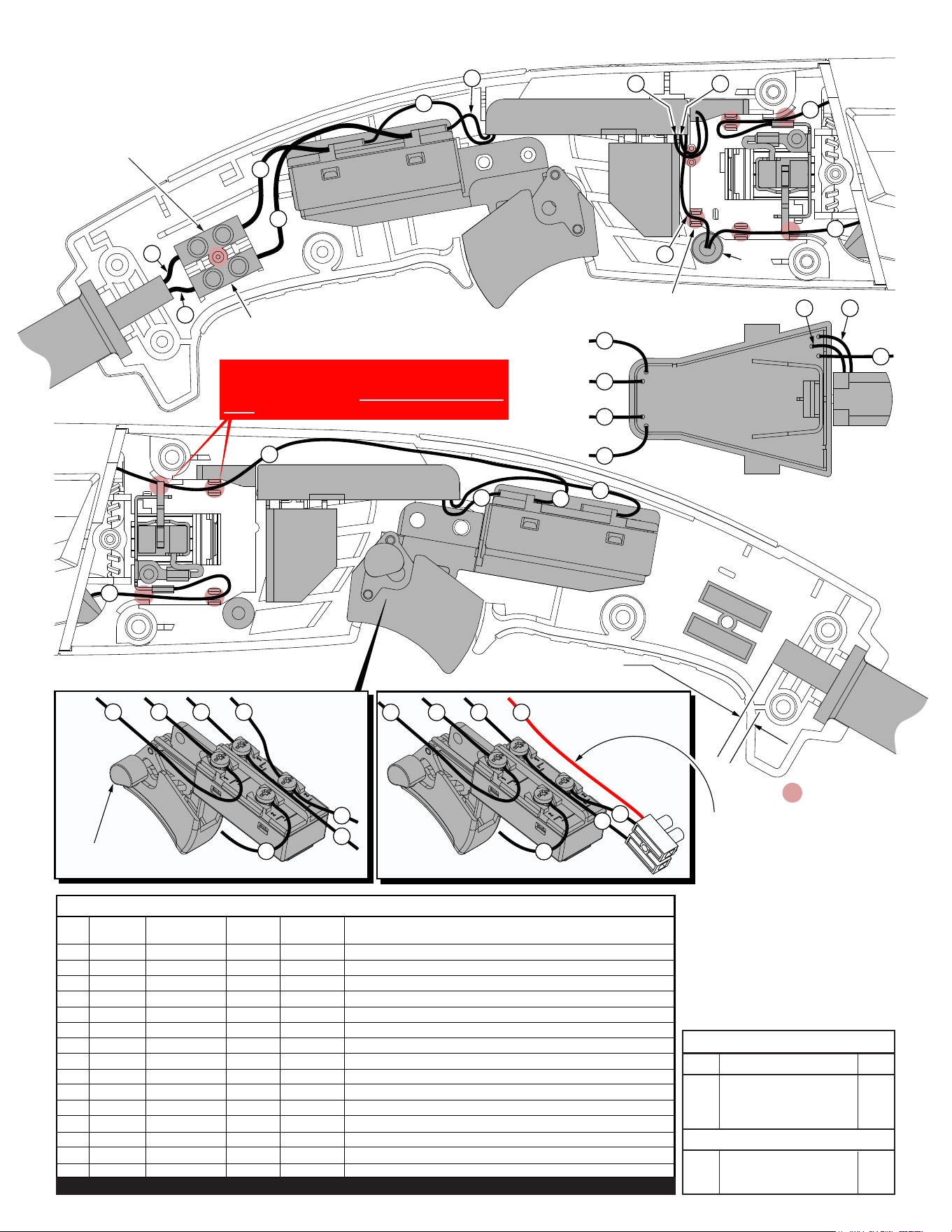
= WIRE TRAPS
or GUIDES
Be sure to fully seat ‘T1’
onto the post in the left
handle halve.
Route wires into traps and
press ‘C1’ into place here.
7
8
4
3
Trigger Switch
(Shown with lock-on feature)
14
5 6
Cord jacket is to extend .25”
beyond the cord clamping area.
Bottom View of the
PCB Assembly
Switch Detail
T1
C1
7
8
4
9
10
5
6
11
3
1
2
6
5
13
12
9
10
11
14
15
14
8
7
7
8
4
3
14
5 6
NOTE:
PCBA wire #6 can be routed
to the lower right switch position
or connect with white wire #4 in
terminal block T1 as shown .
NOTE:
When servicing tool, it is VERY IMPORTANT
that wire #14 is placed completely down in wire
traps behind and away from the brush spring.
AS AN AID TO REASSEMBLY, TAKE NOTICE OF WIRE ROUTING AND
POSITION IN WIRE GUIDES AND TRAPS WHILE DISMANTLING TOOL.
BE CAREFUL AND AVOID PINCHING WIRES BETWEEN
HANDLE HALVES WHEN ASSEMBLING.
Qnty.
TERMINAL DESCRIPTION
PartNo.Code
NOTE:
Allleadsmustbeheldto±1/16".
Allleadlengthsarebeforestripping.
CONNECTOR DESCRIPTION
T1 22-56-0475 1
C1 22-56-0150 1
Wire Wire Origin or
No. Color PartNo. Gauge Length Terminals,ConnectorsandEndWirePreparation
1 Black 22-64-3425 -- -- ComponentofCordSet.ConnecttoT1asshown.
2 White 22-64-3425 -- -- ComponentofCordSet.ConnecttoT1asshown.
3 Black 23-94-0345 -- --
Comp.ofLeadwireAssemblyKit.ConnecttoSwitchandT1asshown.
4 White 23-94-0345 -- --
Comp.ofLeadwireAssemblyKit.ConnecttoSwitchandT1asshown.
5 Black 22-09-1850 -- -- Comp.ofPCBAssembly.ConnecttoSwitchasshown.
6 White 22-09-1850 -- -- Comp.ofPCBAssy.ConnecttoSwitchorT1asshown.
7 Black 22-09-1850 -- -- Comp.ofPCBAssembly.ConnecttoSwitchasshown.
8 White 22-09-1850 -- -- Comp.ofPCBAssembly.ConnecttoSwitchasshown.
9 Red 22-09-1850 -- -- Comp.ofPCBAssembly.ConnecttoWire#12withC1.
10 Black 22-09-1850 -- -- ComponentofPCBAssembly.
11 White 22-09-1850 -- -- ComponentofPCBAssembly.
12 Black 18-07-0310 -- -- Comp.ofField.ConnecttoWire#9withC1asshown.
13 Black 18-07-0310 -- -- Comp.ofField.ConnecttoRightBrushAssy.asshown.
14 Black 18-07-0310 -- -- ComponentofField.ConnecttoSwitchasshown.
15 Black 18-07-0310 -- -- Comp.ofField.ConnecttoLeftBrushAssy.asshown.
BULK LEAD WIRE - BULLETIN 58-01-0003
WIRING SPECIFICATIONS