
24

1
1400A POWER STATION
INSTRUCTION MANUAL
VECJ14C
SAVE THIS INSTRUCTION MANUAL FOR FUTURE REFERENCE.
© 2024 Baccus Global LLC
Boca Raton, FL 33432
(877) 571-2391
BC
2
This device complies with part 15 of the FCC rules. Operation is subject to the following two conditions: (1) this device may not cause harmful interference, and (2) this device must accept any interference
received, including interference that may cause undesired operation.
This equipment has been tested and found to comply with the limits for a Class B digital device, pursuant to part 15 of the FCC Rules. These limits are designed to provide reasonable protection against harmful
interference in a residential installation. This equipment generates, uses and can radiate radio frequency energy and, if not installed and used in accordance with the instructions, may cause harmful interference
to radio communications. However, there is no guarantee that interference will not occur in a particular installation. If equipment does cause harmful interference to radio or television reception, which can be
determined by turning the equipment off and on, the user is encouraged to try to correct the interference by one or more of the following measures:
• Reorient or relocate the receiving antenna.
• Increase the separation between equipment and receiver.
• Connect the equipment into an outlet on a circuit different from that to which the receiver is connected.
• Consult the dealer or an experienced radio/TV technician for help.
Changes or modifications not approved by the party responsible for compliance could void user’s authority to operate the equipment.
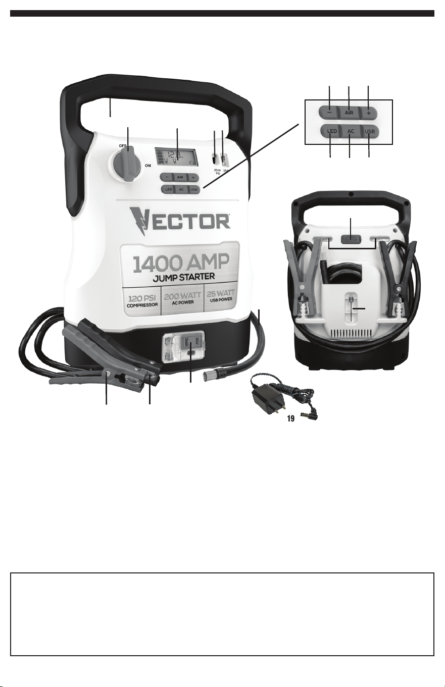
FEATURES
1. Handle
2. Jump-Starter Power Switch
3. LCD Screen
4. USB-C Port
5. USB-A Port
6. Compressor Pressure Control Button (–)
7. Compressor Power Button
8. Compressor Pressure Control Button (+)
9. Area Light Power Button
10. AC Power Button
11. USB Power Button
12. 120 Volt AC Outlet
13. LED Area Lights
14. 12 Volt DC Charging Port (for Use with 120 Volt AC Charger)
15. Positive (+) Red Clamp
16. Negative (–) Black Clamp
17. Air Hose and Sure Fit® Nozzle Connector
18. Nozzle Adapter
19. 120 Volt AC Charger
FEATURES
5
4
6
7
8
9
1
2
3
19
12
13
17
15
18
14
16
6
7
8
9
4
5
10
11

3
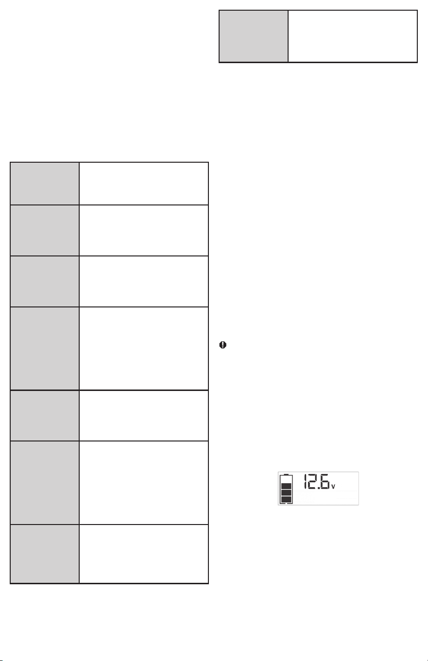
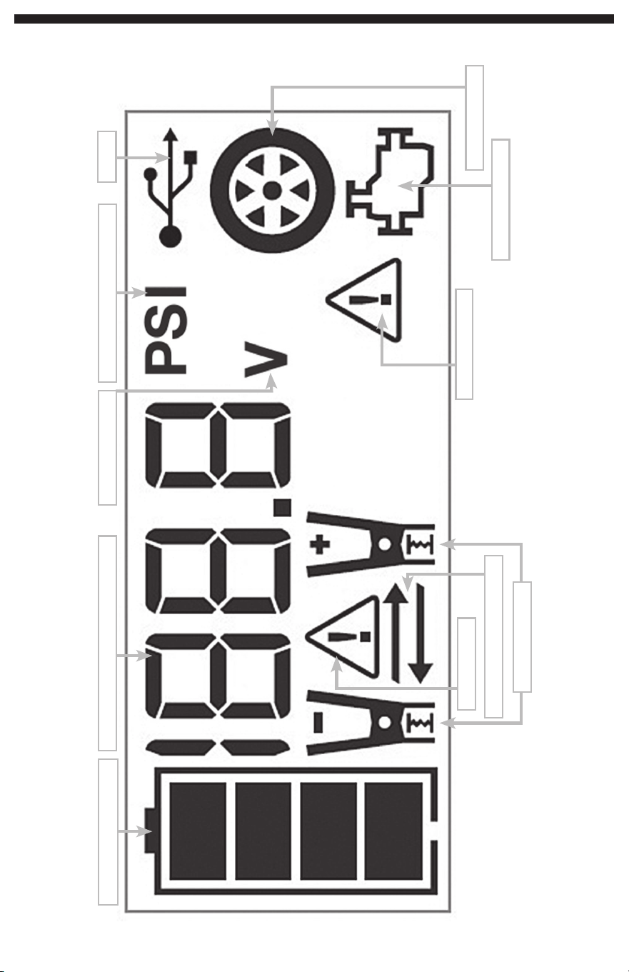
LCD DISPLAY DETAIL
BATTERY STATUS ICON
DIGITAL DISPLAY (VARIES BY FUNCTION)
ALARM ICON
REVERSE POLARITY ICONS
CLAMP ICONS
COMPRESSOR PRESSURE INDICATOR
USB ICON
COMPRESSOR ICON
JUMP STARTER ICON
FAULT ICON
VOLTAGE INDICATOR

4
SAFETY GUIDELINES /
DEFINITIONS
DANGER: Indicates an imminently hazardous situation which, if not
avoided, will result in death or serious injury.
WARNING: Indicates a potentially hazardous situation which, if not
avoided, could result in death or serious injury.
CAUTION: Indicates a potentially hazardous situation which, if not
avoided, may result in minor or moderate injury.
CAUTION: Used without the safety alert symbol indicates potentially
hazardous situation which, if not avoided, may result in property damage.
RISK OF UNSAFE OPERATION: When using tools or equipment, basic
safety precautions should always be followed to reduce the risk of
personal injury. Improper operation, maintenance or modification of tools
or equipment could result in serious injury and property damage. There
are certain applications for which tools and equipment are designed.
Manufacturer strongly recommends that this product NOT be modified
and/or used for any application other than for which it was designed. Read
and understand all warnings and operating instructions before using any
tool or equipment.
READ ALL INSTRUCTIONS
WARNING: Read all instructions before operating power station.
Failure to follow all instructions listed below may result in electric
shock, fire and/or serious injury.
IMPORTANT SAFETY
INSTRUCTIONS
GENERAL SAFETY WARNINGS AND INSTRUCTIONS
• This unit was designed for household use only.
WARNING – Risk of fire, electric shock, burst hazard, or injury to
persons or property
• Avoid dangerous environments. Don’t use appliances in damp or wet
locations. Don’t use appliances in the rain.
• Keep children away. All visitors should be kept at a distance from work
area.
• Dress properly. Do not wear loose clothing or jewelry. They can be
caught in moving parts. Rubber gloves and substantial, non-skid footwear
are recommended when working outdoors. Wear protective hair covering
to contain long hair.
• Use safety glasses and other safety equipment. Use safety goggles
or safety glasses with side shields, complying with applicable safety
standards. Safety glasses or the like are available at extra cost at your
local dealer.
• Store idle appliance indoors. When not in use, appliances should be
stored indoors in a dry and high or locked-up place – out of reach of
children.
• Don’t abuse cord. Never carry appliance by cord or yank it to disconnect
from receptacle. Keep cord from heat, oil, and sharp edges.
• Disconnect appliances. Disconnect the appliance from the power supply
when not in use, before servicing, and when changing accessories.
• Ground Fault Circuit Interrupter (GFCI) protection should be provided
on the circuits or outlets to be used. Receptacles are available having built
in GFCI protection and may be used for this measure of safety.
• Use of accessories and attachments. The use of any accessory or
attachment not recommended for use with this appliance could be
hazardous. Refer to the accessory section of this manual for further
details.
• Stay alert. Use common sense. Do not operate this equipment when you
are tired or impaired.
• Check for damaged parts. Do not use if damaged in any way.
• Do not operate this appliance near flammable liquids or in gaseous
or explosive atmospheres. Motors in these tools normally spark, and the
sparks might ignite fumes.
• Never submerge this unit in water; do not expose it to rain, snow or
use when wet.
• To reduce risk of electric shock, disconnect the unit from any power
source before cleaning. Turning off controls without disconnecting will not
reduce this risk.
• This equipment employs parts (switches, relays, etc.) that produce
arcs or sparks. Therefore, if used in a garage or enclosed area, the unit
MUST be placed not less than 18 inches above the floor.
SPECIFIC SAFETY INSTRUCTIONS FOR CHARGING THIS UNIT
• IMPORTANT: This unit is delivered in a partially charged state. Fully charge
unit with the supplied AC charger until the Battery Status Icon shows 4
solid bars before using for the first time. You cannot overcharge the unit
using the AC charging method.
• To recharge this unit, use only the supplied AC charger.
• All functions should be turned off when the unit is charging or not in
use. Make sure all functions are turned off before connection to a power
source or load.
EXTENSION CORDS:
WARNING: Use of improper extension cord could result in a risk of fire
and electric shock. When using an extension cord, make sure that the
pins of the extension cord are the same number, size and shape as those
in the charger; and be sure to use one heavy enough to carry the current
your product will draw. An undersized cord will cause a drop in line voltage
resulting in loss of power and overheating. The following table shows the
correct size to use depending on cord length and nameplate ampere rating.
If in doubt, use the next heavier gauge. The smaller the gauge number, the
heavier the cord.
MINIMUM GAUGE FOR CORD SETS
Volts Total Length of Cord in Feet
120V 0-25 26-50 51-100 101-150
(0-7.6m) (7.6-15.2m) (15.2-30.4m) (30.4-45.7m)
240V 0-50 51-100 101-200 201-300
(0-15.2m) (15.2-30.4m) (30.4-60.9m) (60.9-91.4m)
Ampere Rating Extension Cord Length
More Not more
0'-25' 26'-50' 51'-100' 101' -150'
Than Than American Wire Gauge (AWG)
0 - 6 18 16 16 14
6 - 10 18 16 14 12
10 - 12 16 16 14 12
12 - 16 14 12 Not Recommended
When an extension cord is used, make sure that:
– the pins of extension cord are the same number, size and shape as
those in the charger,
– the extension cord is properly wired and in good electrical condition,
– the wire size is large enough for the AC rating of the charger.
CAUTION – To reduce the risk of injury or property damage: Pull the
extension cord by the plug rather than the cord when disconnecting from
the supplied AC Charger or the AC outlet.
SPECIFIC SAFETY INSTRUCTIONS FOR JUMP STARTERS
WARNING: Burst hazard
Do not use the unit for charging dry-cell batteries that are commonly
used with home appliances. These batteries may burst and cause injury
to persons and damage property. Use the unit for charging/boosting a
lead-acid battery only. It is not intended to supply power to a low-voltage
electrical system other than in a starter-motor application.
• Use of an attachment not supplied, recommended or sold by
manufacturer specifically for use with this unit may result in a risk of
electrical shock and injury to persons.
WARNING: Risk of explosive gases
• Working in the vicinity of a lead acid battery is dangerous. Batteries
generate explosive gases during normal battery operation. For this reason,
it is of the utmost importance that each time before using the jump starter
you read this manual and follow instructions exactly.
• To reduce the risk of battery explosion, follow these instructions and those
published by the battery manufacturer and manufacturer of any equipment
you intend to use in the vicinity of the battery. Review cautionary markings
on these products and on the engine.

5
CAUTION – To reduce the risk of injury or property damage:
• NEVER ATTEMPT TO JUMP-START OR CHARGE A FROZEN BATTERY.
• Vehicles that have on-board computerized systems may be damaged if
vehicle battery is jump-started. Before jump-starting, read the vehicle’s
owner’s manual to confirm that external-starting assistance is suitable.
• Never smoke or allow a spark or flame in vicinity of vehicle battery, engine
or power station.
• Stay clear of fan blades, belts, pulleys, and other parts that can cause
injury to persons.
• Remove personal metal items such as rings, bracelets, necklaces and
watches when working with a lead acid battery. A lead acid battery can
produce a short circuit current high enough to weld a ring, or similar metal
object, to skin, causing a severe burn.
• Do not wear vinyl clothing when jump-starting a vehicle. Friction can
cause dangerous static-electrical sparks.
• Be extra careful to avoid dropping a metal tool onto the battery. It might
spark or short-circuit the battery or another electrical part and could cause
an explosion.
• Jump-start procedures should only be performed in a safe, dry, well-
ventilated area.
• Always store battery clamps when not in use. Never touch battery
clamps together. This can cause dangerous sparks, power arcing and/
or explosion.
• When using this unit close to the vehicle’s battery and engine, stand
the unit on a flat, stable surface, and be sure to keep all clamps, cords,
clothing and body parts away from moving vehicle parts.
• Never allow red and black clamps to touch each other or another
common metal conductor — this could cause damage to the unit and/or
create a sparking/explosion hazard.
a) For negative-grounded systems, connect the Positive (Red) Clamp to
the positive ungrounded battery post and the Negative (Black) Clamp
to the vehicle chassis or engine block away from the battery. Do not
connect the clamp to the carburetor, fuel lines or sheet-metal body
parts. Connect to a heavy gauge metal part of the frame or engine
block.
b) For positive-grounded systems, connect the Negative (Black) Clamp
to the negative ungrounded battery post and the Positive (Red) Clamp
to the vehicle chassis or engine block away from the battery. Do not
connect the clamp to the carburetor, fuel lines or sheet-metal body
parts. Connect to a heavy gauge metal part of the frame or engine
block.
• If the clamps are connected incorrectly with regard to polarity, the backlit
LCD Screen will display the Battery Status Icon, Battery Voltage Indicator,
and the Clamp Icons. The Alarm Icon, the “+” and ”–” signs and the
Reverse Polarity Icons will flash and the unit will sound a continuous alarm
until the clamps are disconnected. Disconnect the clamps and reconnect
to battery with correct polarity.
• Always disconnect the negative (black) jumper cable first, followed by the
positive (red) jumper cable, except for positive grounded systems.
• Do not expose battery to fire or intense heat since it may explode. Before
disposing of the battery, protect exposed terminals with heavy-duty
electrical tape to prevent shorting (shorting can result in injury or fire).
• Place this unit as far away from the battery as cables permit.
• Never allow battery acid to come in contact with this unit.
• Do not operate this unit in a closed area or restrict ventilation in any way.
• This system is designed to be used only on vehicles with a 12 volt DC
battery system. Do not connect to a 6 volt or 24 volt battery system.
• This system is not designed to be used as a replacement for a vehicular
battery. Do not attempt to operate a vehicle that does not have a battery
installed.
• Excessive engine cranking can damage a vehicle’s starter motor. If
the engine fails to start after the recommended number of attempts,
discontinue jump-start procedures and look for other problems that may
need to be corrected.
• Do not use this jump starter on a watercraft. It is not qualified for marine
applications.
• Although this unit contains a non-spillable battery, it is recommended that
unit be kept upright during storage, use and recharging. To avoid possible
damage that may shorten the unit’s working life, protect it from direct
sunlight, direct heat and/or moisture.
SPECIFIC SAFETY INSTRUCTIONS FOR INVERTERS
WARNING – To reduce the risk of electric shock:
• Do not connect to AC distribution wiring.
• Do not make any electrical connections or disconnections in areas
designated as IGNITION PROTECTED. This inverter is NOT approved for
ignition protected areas.
• Never immerse the unit in water or any other liquid, or use when wet.
WARNING – To reduce the risk of fire:
• Do not operate near flammable materials, fumes or gases.
• Do not expose to extreme heat or flames.
CAUTION – To reduce the risk of injury or property damage:
• Disconnect appliance plug from inverter outlet before attempting any
repairs to the appliance.
• When an appliance plugged into this unit is used outdoors, use only
extension cords intended for use outdoors and so marked.
• Do not attempt to connect the inverter while operating your vehicle. Not
paying attention to the road may result in a serious accident.
• Always use the inverter where there is adequate ventilation.
• Always turn the inverter off when not in use.
• Keep in mind that this inverter will not operate high wattage appliances
or equipment that produce heat, such as hair dryers, microwave ovens
and toasters.
• Do not use this inverter with medical devices. It is not tested for medical
applications.
• Operate inverter only as described in this Instruction Manual.
SPECIFIC SAFETY INSTRUCTIONS FOR THE USB PORT
• Do not insert foreign objects into the USB Ports.
• Do not attach USB hubs or more than one personal electronic device to
the USB Ports.
• Some household USB-powered electronics will not operate with this unit.
• Do not use this unit to operate appliances that require more than 15W
when using the USB-A Port only; 25W when using the USB-C Port only;
up to 5V/15W output on both the USB-A and USB-C when they are used
simultaneously.
SPECIFIC SAFETY INSTRUCTIONS FOR COMPRESSORS
CAUTION – To reduce the risk of injury or property damage: Never
leave the compressor unattended while in use.
WARNING – Burst hazard: Bursting articles can cause serious injury.
• Carefully follow instructions on articles to be inflated.
• Never exceed the recommended pressure listed in instructions on articles
to be inflated. If no pressure is given, contact article manufacturer before
inflating.
• Monitor the pressure at all times on the pressure gauge.
CAUTION – To reduce the risk of property damage:
Do not operate compressor continuously for longer than approximately
10 minutes, depending on ambient temperatures, as it may overheat. This
could damage the compressor.
FIRST AID
When working with lead acid batteries, always make sure immediate
assistance is available in case of accident or emergency.
Always have protective eyewear when using this product: contact with
battery acid may cause blindness and/or severe burns. Be aware of first
aid procedures in case of accidental contact with battery acid.
Have plenty of fresh water and soap nearby in case battery acid contacts
skin.
•
Skin: If battery acid comes in contact with skin, rinse immediately with
water, then wash thoroughly with soap and water. If redness, pain, or
irritation occurs, seek immediate medical attention.
•
Eyes: If battery acid comes in contact with eyes, flush eyes immediately,
for a minimum of 15 minutes and seek immediate medical attention.
•
LCD liquid crystal display: If liquid crystal comes in contact
with your skin: Wash area off completely with plenty of water. Remove
contaminated clothing. If liquid crystal gets into your eye: Flush the
affected eye with clean water and then seek medical attention. If liquid
6
crystal is swallowed: Flush your mouth thoroughly with water. Drink large
quantities of water and induce vomiting. Then seek medical attention.
SAVE THESE
INSTRUCTIONS
INTRODUCTION
Congratulations on purchasing your new
Power Station.
Read this
Instruction Manual and follow the instructions carefully before using this
unit.
OVERVIEW
Common Actions and Unit Responses
Press the LED Area
Light Power Button.
A beep will sound and the Area Light will turn
on. The backlight will turn on for 10 seconds
(only). The LCD Screen will continue to display
the Battery Status and Voltage Indicator. The
LED Area Light remains on until switched off.
Press the AC Power
Button.
A beep will sound and the backlit LCD Screen
will display the Battery Status Icon and the
Digital Display shows “AC”, indicating the AC
Outlet is ready to use. The unit remains on
until the AC Power Button is pressed again to
turn it off.
Press the USB Power
Button.
A beep will sound and the USB Ports will turn
on. The LCD Screen will display the Battery
Status Icon, Battery Voltage Indicator, and the
USB Icon, indicating the USB Ports are ready
to use. The unit remains on until the USB
Power Button is pressed again to turn it off.
Press the Compressor
Power Button.
A beep will sound and the backlit LCD
Screen will display the Battery Status and the
Compressor Icon and will alternately show the
flashing pre-set PSI value (that was last set
using the compressor pressure control buttons)
and the current pressure of the item being
inflated (which will light solid). If no further
actions are taken after 1 minute, the unit will
display the Battery Status and Voltage Indicator
for 10 seconds before automatically turning off.
Whenever the
clamps are properly
connected to a battery
(refer to the “Jump
Starter” section) …
… a beep will sound and the backlit LCD
Screen will display the Battery Status Icon,
Battery Voltage Indicator, the Clamp Icons, and
the “+” and ”–” signs, as well as the flashing
Jump Starter Icon. The unit remains on until
the clamps are disconnected from the battery.
If the Jump Starter
Power Switch is
rotated to the on
position and the
clamps are not
connected to a battery
(refer to the “Jump
Starter” section) …
... a two-second warning will sound every 10
seconds. The backlit LCD Screen will display
the Battery Status Icon, Battery Voltage
Indicator, the Clamp Icons, and the “+” and ”–”
signs. The Alarm Icon and the Jump Starter
Icon will flash. The unit remains on until the
Jump Starter Power Switch is switched off and
then displays the Battery Status Icon and the
voltage of digital display for 10 seconds before
automatic shut down.
If the clamp
connections to the
battery’s positive and
negative terminals are
reversed …
… the backlit LCD Screen will display the
Battery Status Icon, Battery Voltage Indicator,
and the Clamp Icons. The Alarm Icon, the “+”
and ”–” signs and the Reverse Polarity Icons
will flash and the unit will sound continuously
until the clamps are disconnected from the
battery.
When the unit is
charging or
recharging using the
supplied 120 Volt AC
Charger …
… the backlight will turn on for 10 seconds
(only). The LCD Screen will continue to display
the Battery Status Icon and Battery Voltage
Indicator. The bars on the Battery Icon will
change from empty to solid (bottom to top)
repeatedly.
Note:
The unit will automatically power off once ALL the functions are turned off.
VIEWING BATTERY STATUS
The Battery Icon will indicate the battery charge level as follows:
• If the battery charge level is at full capacity, four solid bars will display.
• If the battery is partially charged, two or three solid bars will display.
• If the battery is nearly empty, one solid bar will display. The unit should be
charged at this time.
• If the battery is completely empty, a blank Battery Status Icon will display.
The unit MUST be charged at this time or the unit’s built-in low voltage
protection will activate. The unit will automatically shut down and may not
operate until the battery is recharged.
CHARGING/RECHARGING
Lead-acid batteries require routine maintenance to ensure a full charge and
long battery life. All batteries lose energy from self- discharge over time
and more rapidly at higher temperatures. Therefore, batteries need periodic
charging to replace energy lost through self-discharge. When the unit is not
in frequent use, manufacturer recommends the battery should be recharged
at least every 30 days and after each use.
IMPORTANT: If you attempt to use the unit when the unit’s battery charge
level is too low, the unit will automatically shut down. Recharge the unit
with all other functions turned off as soon as possible.
Notes:
This unit is delivered in a partially charged state – you must fully charge it
before using it for the first time. Initial AC charge should be about 30 hours or
until the Battery Status Icon shows 4 solid bars..
Recharging battery after each use will prolong battery life; frequent heavy
discharges between recharges and/or overcharging will reduce battery life.
Make sure all other unit functions are turned off during recharging, as this can
slow the recharging process.
CAUTION – Risk of property damage: Failure to keep the battery
charged will cause permanent damage and result in poor jump starting
performance.
IMPORTANT: If you know the unit is discharged, but the Battery Icon
displays four solid bars as if the unit is fully charged when connected to
a charging power source, this may be due to the internal battery having
high impedance. The manufacturer suggests leaving the unit charging for a
period of 40 hours using the supplied AC charger before use.
Charging/Recharging Using the Supplied AC Charger
1. Insert the barrel connector of the AC charger into the 12 Volt DC
Charging Port on the back of the unit. Insert the plug end into a
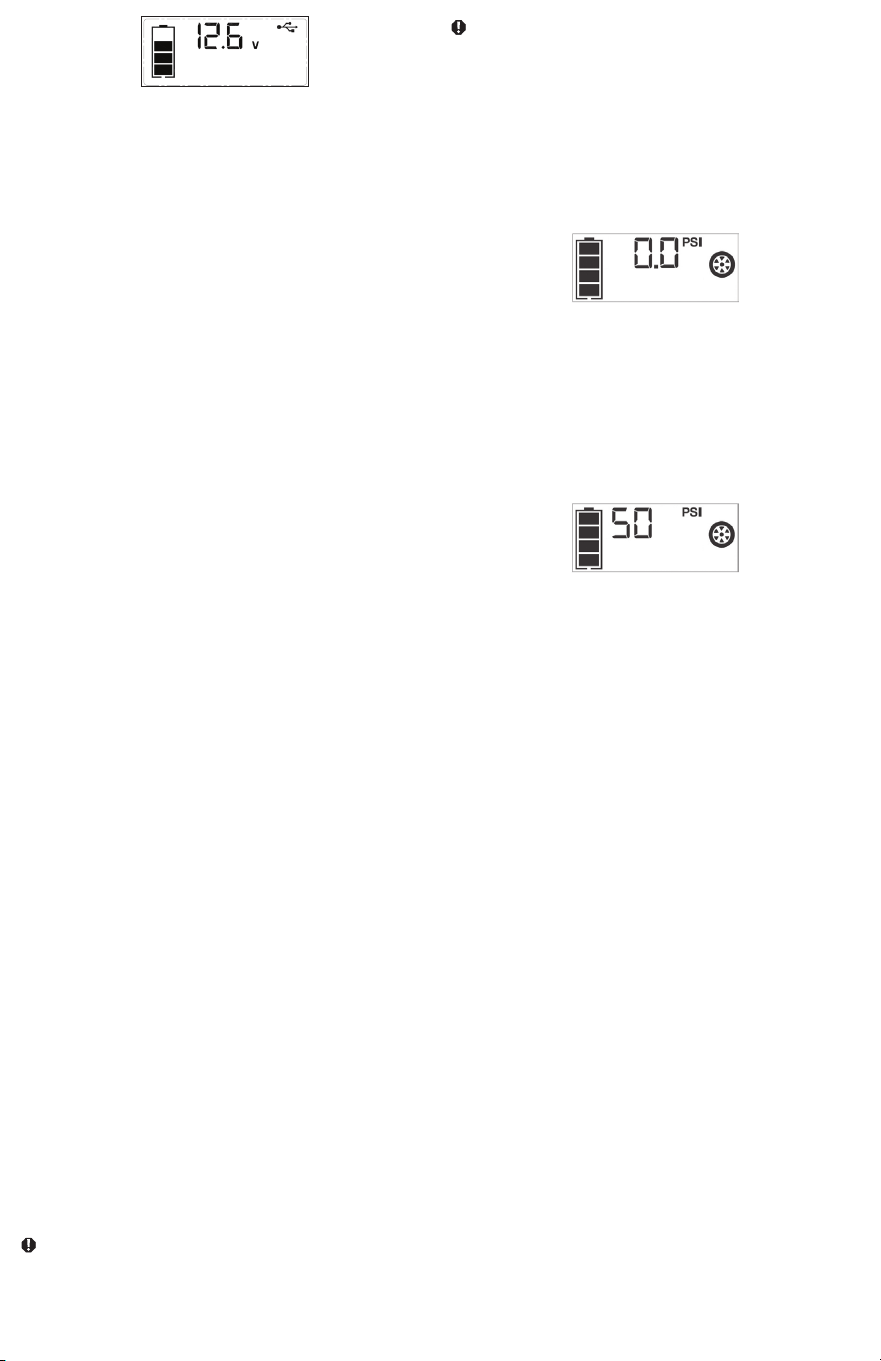
(powered) standard North American 120 volt 60Hz outlet. When the
unit is properly connected to an AC power source, the LCD Screen will
display the following (the screen will be backlit):
will be backlit):
The bars on the Battery Icon represent the capacity level of the unit’s
internal battery. After 10 seconds, the backlight will shut off.
The bars on the Battery Icon will change from empty to solid (bottom
to top) repeatedly to indicate the unit is charging.
2. Charge until the Battery Icon shows 4 solid bars.
3. When charging is complete, disconnect the AC charger from the unit –
first unplug the charger from the AC power source, then disconnect the
barrel connector from the unit.
JUMP STARTER
IMPORTANT: All features must be turned off with the exception of the Area
Light when jump-starting. The unit is intended to be used only in the
upright position.
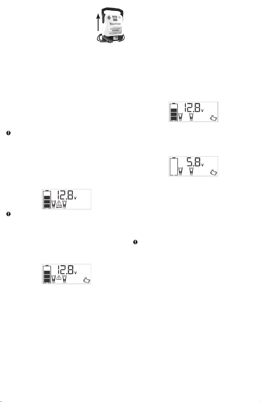
7
The unit must be kept upright during use. See the
illustration to the right for correct orientation.
This unit is equipped with a Jump Starter Power Switch that allows energy
to flow only when proper connections are made to battery and frame.
1. For negative-grounded systems, connect the Positive (Red) Clamp to
the positive ungrounded battery post and the Negative (Black) Clamp
to the vehicle chassis or engine block away from the battery. Do not
connect the clamp to the carburetor, fuel lines or sheet-metal body
parts. Connect to a heavy gage metal part of the frame or engine
block.
2. For positive-grounded systems, connect the Negative (Black) Clamp
to the negative ungrounded battery post and the Positive (Red) Clamp
to the vehicle chassis or engine block away from the battery. Do not
connect the clamp to the carburetor, fuel lines or sheet-metal body
parts. Connect to a heavy gage metal part of the frame or engine
block.
IMPORTANT: Make sure the Compressor has been turned off before
attempting to use the unit as a Jump Starter.
WARNING – To reduce the risk of serious injury or property damage:
• Follow all safety instructions found in the “Specific Safety Instructions for
Jump Starters” section of this Instruction Manual.
• Never touch red and black clamps together. This can cause dangerous
sparks, power arcing, and/or explosion.
• If the clamps are connected incorrectly with regard to polarity, the unit will
sound a continuous alarm until the clamps are disconnected. The backlit
LCD Screen will display the Battery Status Icon, the Battery Voltage
Indicator and the Clamp Icons. The “+” and”–” signs above the Clamp
Icons, the Arrow Icons and the Alarm Icon will flash. The backlit LCD
Screen will display the following:
CAUTION: The unit will suffer permanent damage if the Jump Starter
Power Switch is turned on while the clamps connected with reverse
polarity. Disconnect the clamps and reconnect to battery with correct
polarity.
• If the Jump Starter Power Switch is turned on and the unit detects that
the clamps are not connected to a battery, a two-second warning will
sound every 10 seconds. The LCD Screen will display the Battery Status
Icon, the Battery Voltage Indicator, and the Clamp Icons with the “+”
and”–” signs. The Alarm Icon and the Jump Starter Icon will flash. The
backlit LCD Screen will display the following:
Turn off the Jump Starter Power Switch; connect the clamps to the
battery, making sure the clamps are connected with correct polarity; then
turn the Jump Starter Power Switch back on.
• Always disconnect the negative (black) jumper cable first, followed by the
positive (red) jumper cable, except for positive grounded systems.
Procedure
Take the following steps, observing all cautions and warnings in the
“Important Safety Instructions” section at the front of this manual.
1. Turn off vehicle ignition and all accessories (radio, A/C, lights,
connected cell phone chargers, etc.). Place vehicle in “park” and set
the emergency brake.
2. Make sure the Jump Starter Power Switch is in the OFF position.
3. Remove jumper clamps from clamp tabs. Connect the Red Clamp first,
then the Black Clamp.
4. Procedure for jump-starting a NEGATIVE GROUNDED SYSTEM
(negative battery terminal is connected to chassis) (MOST COMMON)
4a. Connect Positive (+) Red Camp to vehicle battery’s positive
terminal.
4b. Connect Negative (–) Black Clamp to chassis or a solid, non-
moving, metal vehicle component or body part. Never clamp
directly to negative battery terminal or moving part. Refer to the
automobile owner’s manual.
5. Procedure for jump-starting POSITIVE GROUND SYSTEMS
Note:
In the rare event that the vehicle to be started has a Positive Grounded
System (positive battery terminal is connected to chassis), replace steps
4a and 4b above with steps 5a and 5b, then proceed to step 6.
5a. Connect Negative (–) Black Clamp to vehicle battery’s negative
terminal.
5b. Connect Positive (+) Red Clamp to vehicle chassis or a solid,
non-moving, metal vehicle component or body part. Never clamp
directly to positive battery terminal or moving part. Refer to the
automobile owner’s manual.
6. When the clamps are connected properly, the backlit LCD Screen will
display the following to indicate the unit is ready to jump-start:
The Battery Status Icon, Battery Voltage Indicator, Clamp Icons and the
“+” and”–” signs light solid. The Jump Starter Icon will flash to indicate
the clamps are properly connected.
7. Turn the Jump Starter Power Switch to ON. Turn on the ignition and
crank the engine in 5-6 second bursts until engine starts. The backlit
LCD Screen will display the following:
The Battery Status Icon, the Battery Voltage Indicator, Clamp Icons and
the “+” and”–” signs light solid to indicate the unit is jump-starting. The
Jump Starter Icon flashes. The Jump Starter Icon lights solid if vehicle
is started.
8. Turn the Jump Starter Power Switch to OFF.
9. Disconnect the Negative (–) Engine or Chassis Clamp first, then
disconnect the Positive (+) Battery Clamp.
Note: If the unit is malfunctioning after jump start procedure, please
recharge the unit with the supplied AC charger to reset the unit.
IMPORTANT: Always turn the unit off when not in use. Recharge this unit fully
after each use.
CAUTION – To reduce the risk of property damage:
• Vehicles that have on-board computerized systems may be damaged if
vehicle battery is jump-started. Before jump-starting this type of vehicle,
read the vehicle manual to confirm that external-starting assistance is
advised.
• Excessive engine cranking can damage the vehicle’s starter motor. If
the engine fails to start after the recommended number of attempts,
discontinue jump-start procedure and look for other problems that need
to be corrected.
• If vehicle fails to start, turn off the ignition, turn off the Jump Starter Power
Switch, disconnect the jump-start system’s leads and contact a qualified
technician to investigate why the engine did not start.
LED AREA LIGHT
The built-in LED Area Light is controlled by the Area Light Power Button on
the control panel (refer to the Features section to locate). Press the Area
Light Power Button once to turn the light on. Press the Area Light Power
Button again to turn the Area Light off.
IMPORTANT: When the Area Light Power Button is pressed to turn it on, a
beep will sound. The backlit LCD Screen will turn on for 10 seconds (only)
and will then continuously display the Battery Status Icon and Battery
Voltage Indicator.
Periodically check the unit’s Battery Status on the backlit LCD Screen.
Four solid bars in the Battery Icon indicates a full battery. When the battery
level is nearly empty with only one solid bar or empty Battery Status Icon,
the unit must be recharged at this time or the unit’s built-in low voltage
8
protection will activate. The unit will automatic shut down after a short
period.
Make sure the Area Light is turned off when the unit is being recharged
or stored.
120 VOLT AC PORTABLE POWER SUPPLY
Rated Versus Actual Current Draw of Equipment
Most electrical tools, appliances, electronic devices and audio/visual
equipment have labels that indicate the power consumption in amps or
watts. Be sure that the power consumption of the item to be operated is
below 200 watts. If the power consumption is rated in amps AC, simply
multiply by the AC volts (120) to determine the wattage.
Resistive loads are the easiest for this unit to run; however, it will not run
larger resistive loads (such as electric stoves and heaters), which require
far more wattage than the unit can deliver on a continuous basis. Inductive
loads (such as TVs and stereos) require more current to operate than do
resistive loads of the same wattage rating.
CAUTION: Rechargeable devices
• Certain rechargeable devices are designed to be charged by plugging
them directly into an AC receptacle. These devices may damage the
inverter or the charging circuit.
• When using a rechargeable device, monitor its temperature for the initial
ten minutes of use to determine if it produces excessive heat.
• If excessive heat is produced, this indicates the device should not be used
with this inverter.
• This problem does not occur with most of the battery-operated
equipment. Most of these devices use a separate charger or transformer
that is plugged into an AC receptacle.
• The inverter is capable of running most chargers and transformers.
Note: Some laptop computers may not operate with this inverter.
Power Inverter Output Waveform
The AC output waveform of this inverter is known as a modified sine wave.
It is a stepped waveform that has characteristics similar to the sine wave
shape of utility power. This type of waveform is suitable for most AC loads,
including linear and switching power supplies used in electronic equipment,
transformers, and small motors.
Protective Features
The inverter monitors the following conditions:
Low internal battery
voltage
The inverter will automatically shut down
when the battery voltage drops too low, as
this can harm the battery.
High internal battery
voltage
The inverter will automatically shut down
when the battery voltage is too high, as this
can harm the unit.
Thermal shutdown
protection
The inverter will automatically shut down
when the unit becomes overheated.
Overload/short circuit
protection
The inverter will automatically shut down
when an overload or short circuit occurs.
IMPORTANT NOTES:
The AC Power Outlet provides a total power draw of 200W.
When the AC Power Outlet is in use, the unit will monitor for the following
fault conditions: thermal fault, low and high battery voltage fault, overload
and short circuit (refer to the “Protective Features” section).
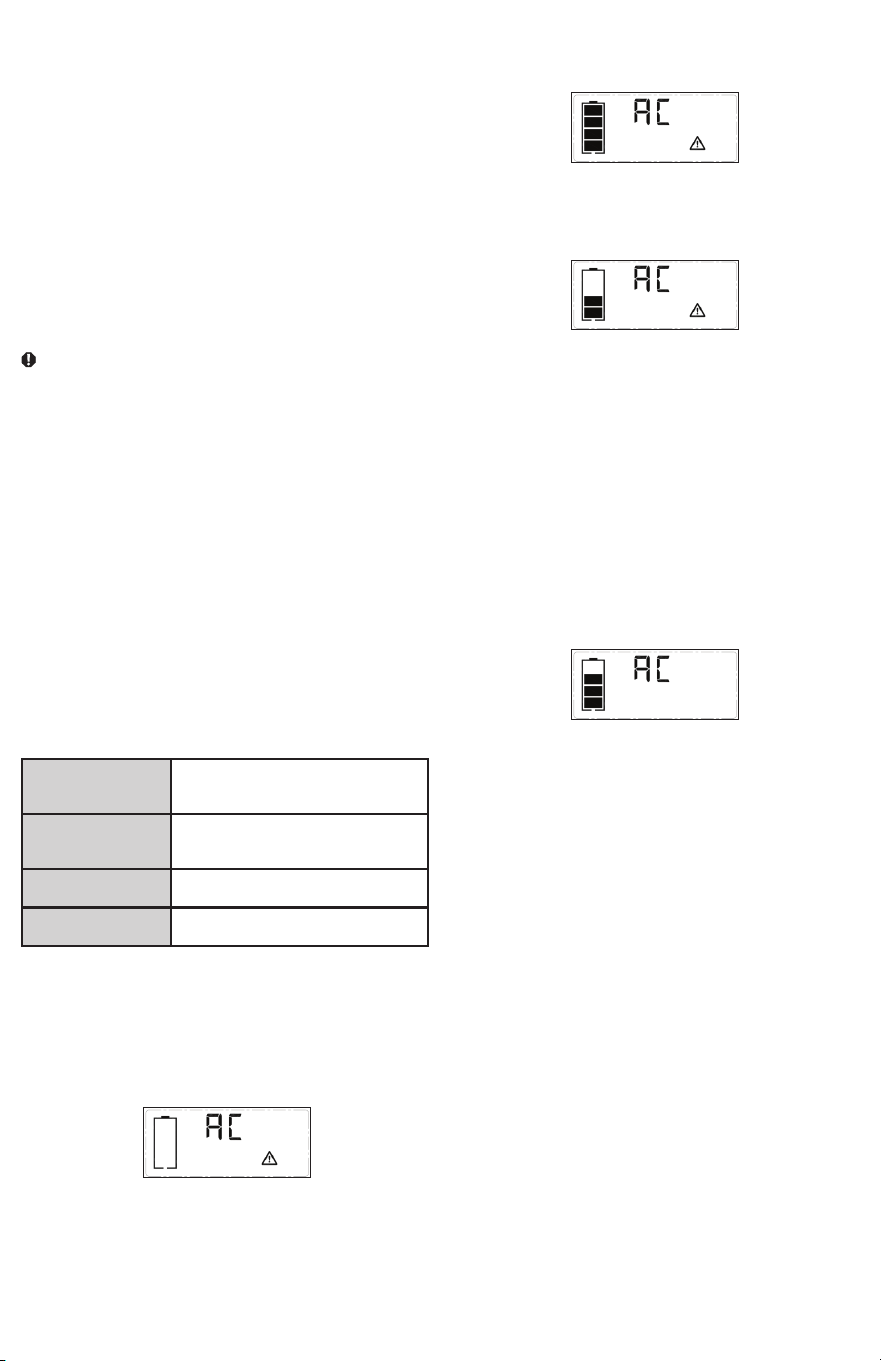
1. If a low internal battery voltage fault condition exists, the AC Power
Outlet will shut down automatically and the backlit LCD Screen will
display the following until the fault is corrected:
The Digital Display will show “AC”; the EMPTY Battery Status Icon
and Fault Icon on the LCD Screen will flash for 60 seconds. After 60
seconds, the Digital Display will show the Battery Voltage Indicator, the
EMPTY Battery Status Icon and Fault Icon on the LCD Screen will flash
for 10 seconds before the unit automatic shut down.
2. If the high internal battery voltage fault condition exists, the AC Power
Outlet will shut down automatically and the backlit LCD Screen will
display the following until the fault is corrected:
The Digital Display will show “AC”; the FULL Battery Status Icon and
Fault Icon on the LCD Screen will flash.
3. If a thermal, overload or short circuit fault condition exists, the AC
Power Outlet will shut down automatically and the backlit LCD Screen
will display the following until the fault is corrected:
4. The Battery Status Icon will light solid; the “AC” on the Digital Display
and the Fault Icon on the LCD Screen will flash.
Should any of the above fault conditions occur:
1. Disconnect the appliance from the unit.
2. Press the AC Power Button to turn the AC Power Outlet off.
3. Make sure the unit does not need to be recharged.
4. Allow the unit to cool down for several minutes.
5. Make sure the rating of the appliance plugged into the unit is 200 watts
or lower and that the appliance cord and plug are not damaged.
6. Assure there is adequate ventilation around the unit before proceeding.
Using the 120 Volt AC Outlet
The 120 Volt AC Outlet is located on the front of the unit. The outlet
supports a maximum power draw of 200 watts.
1. Press the AC Power Button to turn on the 120V AC Power Outlet. A
beep will sound and the LCD Screen will display the following:
The Battery Status Icon lights solid and the Digital Display shows “AC”
Icon, indicating the AC outlet is ready to use.
2. Insert the 120 volt AC plug from the appliance into the 120 Volt AC
Outlet.
3. Switch on the appliance and operate as usual.
Note: Ensure that the wattage of the equipment plugged into the
120V AC Power Outlet does not exceed 200 watts continuous.
4. Press the AC Power Button again to turn off the 120V AC Power
Outlet.
Periodically check the unit’s Battery Status on the backlit LCD Screen.
Four solid bars in the Battery Icon indicates a full battery. When the battery
level is nearly empty with only one solid bar or empty Battery Status Icon,
the unit must be recharged at this time or the unit’s built-in low voltage
protection will activate. The empty Battery Status Icon will flash for a short
period of time before automatic shut down.
IMPORTANT:
• Make sure the AC Power Outlet is turned off when the unit is being
recharged or stored.
• The inverter will automatically shut down when the unit is switched to
charging/recharging mode.
USB CHARGING PORTS
The USB Power Button and the two USB Ports are located on the front
of unit.
1. Press the USB Power Button to turn the USB Ports on. A beep
will sound and the backlit LCD Screen will continuously display the
following:
9
The Battery Status Icon and Battery Voltage Indicator will light solid, as
well as the USB Icon, indicating the USB ports are ready to use.
2. Plug the USB-powered device(s) into the USB Power Port(s) and
operate normally.
Press the USB Power Button again to turn off the USB Ports. Make sure
the USB Ports are turned off when the unit is being recharged or stored.
IMPORTANT NOTES:
The USB-A Port provides up to 15W output power. The USB-C Port
provides up to PD 25W output power. The total output is up to 5V/15W
when the USB-C and USB-A used simultaneously.
When the USB Ports are in use, the unit will monitor for the following USB
fault conditions on the USB Ports: low battery voltage fault, overload and
short circuit.
If a low internal battery voltage fault condition exists, the Digital Display
will show the Battery Voltage Indicator, the EMPTY Battery Status Icon
and Fault Icon on the LCD Screen will flash for 10 seconds before the unit
automatic shut down.
If overload or short circuit fault condition exists, the USB Ports will shut
down automatically.
Should this occur:
• Disconnect the USB-powered device and press the USB Power Button
again to turn it off immediately.
• Make sure the unit does not need to be recharged.
• Allow the unit to cool down for several minutes before attempting to use
the USB Ports again.
• If a fault occurs again, make sure that the total draw of the USB devices
plugged into the USB ports do not exceed the maximum rating.
• If individual USB device is within specifications and the fault occurs, have
the USB device checked for malfunction and do not continue to use it
with the USB Ports.
Periodically check the unit’s Battery Status on the backlit LCD Screen.
Four solid bars in the Battery Icon indicates a full battery. When the battery
level is nearly empty with only one solid bar or empty Battery Status Icon,
the unit must be recharged at this time or the unit’s built-in low voltage
protection will activate. The empty Battery Status Icon will flash for a short
period of time before automatic shut down.
Notes:
• This unit’s USB Power Ports do not support data communication. They
only provide power to external USB-powered devices.
• Some household USB-powered electronics will not operate with this unit.
PORTABLE COMPRESSOR
The built-in 12 volt DC compressor is the ultimate compressor for vehicle
tires, trailer tires and recreational inflatables. A nozzle adaptor is supplied
that screws onto the end of the Sure Fit
®
nozzle at the free end of the
compressor hose. The compressor hose with tire fitting is stored in the
storage compartment. Refer to the “Features” illustration for locations of
compressor hose. The Compressor Power Button and Increase (+) and
Decrease (–) Compressor Pressure Control Buttons are located on the
control panel on the front of the unit.
Before proceeding, check the unit’s Battery Status on the LCD Screen.
Four solid bars in the Battery Icon indicates a full battery. When the battery
level is nearly empty with only one solid bar, the unit MUST be recharged
before use or the unit’s built-in low voltage protection will activate. The
empty Battery Status Icon will flash for a short period of time before
automatic shut down.
The compressor is capable of inflating up to 120 pounds per square inch
(PSI) pressure. The compressor can operate long enough to fill up to 3
average sized tires before the battery must be recharged. Return hose to
the storage compartment after use.
IMPORTANT: Make sure the Jump Starter Power Switch has been turned off
before attempting to use the unit as a Compressor.
WARNING – To reduce the risk of serious injury or property damage:
Follow all safety instructions found in the “Specific Safety Instructions for
Compressors” section of this instruction manual.
CAUTION – To reduce the risk of serious injury or property damage:
Do not operate compressor continuously for longer than 10 minutes, as it
may overheat. This could damage the compressor. If the compressor must
be operated for longer periods: every 10 minutes press the Compressor
Power Button to turn the compressor off, then restart after a cooling down
period of approximately 30 minutes. In any event, the compressor will
automatically shut down after operating continuously for 10 minutes.
Inflating Tires or Products With Valve Stems
1. Screw the Sure Fit
®
nozzle onto the valve stem. Do not overtighten.
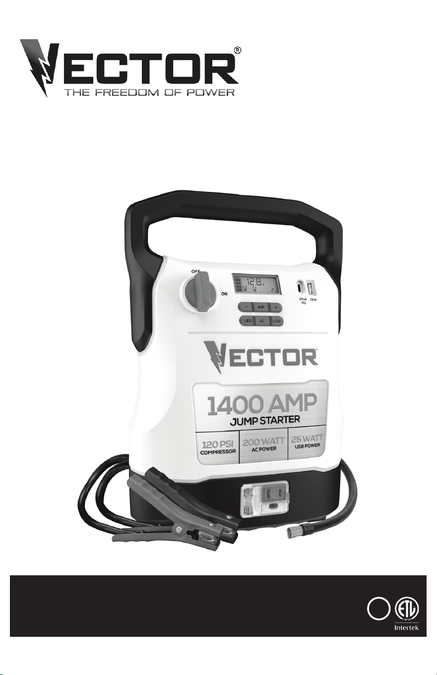
2. Press the Compressor Power Button. A beep will sound and the backlit
LCD Screen will display the following:
The Compressor Icon will light and the digital display will alternately
show the flashing pre-set PSI value (that was last set by the
compressor pressure control buttons) and the current pressure of the
item being inflated (which will light solid).
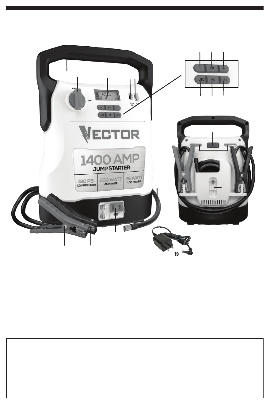
3. Press the “+” and “–” Pressure Control Buttons to set the desired
pressure from a range pre-set values (between 3 and 120), which will
display on the backlit LCD Screen. The unit will sound a beep with
each press of the buttons (holding the button speeds up the upward
or downward value selection). Once the desired pressure has been
entered, release the button and the flashing digital display will show the
new selected pressure, as follows:
The new selected value is now stored in the unit’s memory until it is
manually reset.
4. Press the Compressor Power Button once more to begin inflating. The
Compressor Icon will flash and the digital display will only show the
current pressure value (which will light solid) to indicate the compressor
is activated. Monitor the pressure on the LCD Screen.
Important Note: To interrupt during inflation, press the Compressor
Power Button again.
5. When desired pre-set pressure is reached, the compressor will
automatically stop.
6. Press the Compressor Power Button again to turn off the unit.
7. Unscrew and remove the Sure Fit
®
nozzle from the valve stem.
8. Allow the unit to cool, then recharge before storing away.
9. Store the compressor hose and Sure Fit
®
nozzle in storage
compartment.
Inflating Other Inflatables Without Valve Stems
Inflation of other items requires use of the nozzle adapter.
1. Screw the nozzle adapter into the Sure Fit
®
nozzle. Do not overtighten.
2. Insert the nozzle adapter into item to be inflated.
3. Follow steps 2 through 4 of the “Inflating Tires or Products With Valve
Stems” section.
IMPORTANT: Small items such as volleyballs, footballs, etc. inflate very
rapidly. Keep this in mind when setting pressure. Take extra care not
to over-inflate.
4. When the desired pressure is reached, the compressor will
automatically stop. Press the Compressor Power Button again to turn
off the unit.
5. Disconnect the adapter from the inflated item.
6. Unscrew and remove the nozzle adapter from the Sure Fit
®
nozzle.
7. Allow the unit to cool, then recharge before storing away.
8. Store the compressor hose, Sure Fit
®
nozzle and nozzle adapter in the
storage compartment.
CARE AND MAINTENANCE
All batteries lose energy from self-discharge over time and more rapidly at
higher temperatures. When the unit is not in use, we recommend that the
battery is charged at least every 30 days.

10
Never submerge the unit in water. If the unit gets dirty, gently clean the
outer surfaces of the unit with a soft cloth.
There are no user-replaceable parts. Periodically inspect the condition of
adapters, connectors and wires.
BATTERY
Please be advised that the battery is designed to last the service life of
the unit and is not replaceable, removable or serviceable. Service life is
dependent on a number of factors including but not limited to the number
of recharge cycles, and proper care and maintenance of the battery by the
end user. Contact manufacturer for any information you may need.
SAFE BATTERY DISPOSAL
Contains a maintenance-free, sealed, non-spillable, lead
acid battery, which must be disposed of properly.
Recycling is required. Failure to comply with local, state
and federal regulations can result in fines, or
imprisonment.
Please recycle.
WARNINGS:
• Do not dispose of the battery in fire as this may result in an explosion.
• Before disposing of the battery, protect exposed terminals
with heavy-duty electrical tape to prevent shorting (shorting can result in
injury or fire).
• Do not expose battery to fire or intense heat as it may explode.
TROUBLESHOOTING
Unit will not charge
• Make sure the AC Power Button has been pressed to turn the inverter off.
• Make sure a suitable gauge extension cord is properly connected to both
the unit and a functioning AC outlet.
Unit fails to jump-start
• Make sure the unit is not being operated in the Compressor mode.
• Make sure unit’s Jump Starter Power Switch is in the on position.
• Make sure a proper polarity cable connection has been established.
• Check that unit has a full charge. Recharge unit if necessary.
120 volt AC outlet will not power appliance
• Make sure the AC Power Button has been pressed to turn the inverter on.
• Make sure the unit is not in charging/recharging mode.
• Make sure you have followed all the steps in the 120 AC portable power
supply instructions carefully.
• Make sure the appliance being powered does not draw more than 200
watts
• Refer to the important notes included in that section that explain common
problems and solutions.
• Check that unit has a full charge. Recharge unit if necessary.
USB Power Port will not power appliance
• Make sure that the USB device plugged into the USB-A Port does not
exceed 15W; the USB device plugged into USB-C Port does not exceed
PD 25W; or the total drained power of the USB-A Port and USB-C Port
do not exceed 15W when they are used simultaneously.
• Make sure the USB Power Button has been pressed to turn the USB
Ports on.
• Some USB-powered household electronics will not operate with this USB
Ports. Check the manual of the corresponding electronic device to confirm
that it can be used with this type of USB Ports.
• Check that unit has a full charge. Recharge unit if necessary.
LED Area Light does not come on
• Make sure the Area Light Power Button has been pressed to turn the
Area Light on.
• Check that unit has a full charge. Recharge unit if necessary.
Portable compressor will not inflate
• Make sure the unit is not being operated in Jump Starter mode.
• Make sure the Compressor Power Button has been pressed to turn the
compressor on.
• Make sure the Sure Fit
®
nozzle connector is securely screwed on to the
valve stem when attempting to inflate tires; or that the nozzle adapter
is securely screwed into the Sure Fit
®
nozzle connector and is inserted
properly into the item to be inflated on all other inflatables.
• The compressor may be overheated. Press the compressor Power
Button to turn the compressor off. Restart after a cooling down period of
approximately 30 minutes.
• Check that unit has a full charge. Recharge unit if necessary.
ACCESSORIES
Recommended accessories for use with your tool may be available from
the manufacturer. If you need assistance regarding accessories, please
contact the manufacturer at (877) 571-2391.
WARNING: The use of any accessory not recommended for use with
this appliance could be hazardous.
TECHNICAL ASSISTANCE
For Customer Service or Technical Assistance, contact the manufacturer at
1-877-571-2391.
ONE-YEAR LIMITED MANUFACTURER’S WARRANTY
The manufacturer, Baccus Global LLC, warrants this product against
defects in materials and workmanship for a period of ONE (1) YEAR
commencing from the date of retail purchase by the original end-user
purchaser or from the date of delivery of the good, whichever occurs later
(“Warranty Period”).
If there is a defect and a valid claim is received by the manufacturer within
the Warranty Period, the defective product can be replaced in the following
ways: (1) Return the product to the manufacturer for replacement. Proof of
purchase may be required by manufacturer. (2) Return the product to the
retailer where product was purchased for an exchange (provided that the
store is a participating retailer). Returns to retailer should be made within
the time period of the retailer’s return policy for exchanges only. Proof of
purchase may be required. Please check with the retailer for their specific
return policy regarding returns that are beyond the time set for exchanges.
This manufacturer’s warranty does not apply to accessories, bulbs, fuses
and batteries; defects resulting from normal wear and tear, accidents;
damages sustained during shipping; alterations; unauthorized use; neglect,
misuse, abuse; and failure to follow instructions for care and maintenance
for the product.
This manufacturer’s warranty gives you, the original retail purchaser,
specific legal rights and you may have other rights which vary from
state to state or province to province. This product is not intended for
commercial use. To register your product with the manufacturer, please
visit www.BaccusGlobal.com.
The photos in this manual may differ from the actual unit.
SPECIFICATIONS
Boost Ampere: 1,400A peak battery
Battery type: Maintenance-free, sealed lead acid, 12V DC
AC input: 14.5VDC, 800mA
USB-C output: 5VDC 3A / 9VDC 2.77A (PD 25W
Max.)
USB-A output: 5VDC, 15W Max.
USB-C & USB-A output simultaneously: 5VDC, 15W Max.
120V AC outlet: 120V AC, 60Hz, 200W continuous
Imported by Baccus Global LLC,
225 NE Mizner Blvd., Suite 301, Boca Raton, FL 33432
www.Baccusglobal.com 1-877-571-2391
RD051424
11
FUENTE DE ALIMENTACIÓN DE 1400A
MANUAL DE INSTRUCCIONES
VECJ14C
GUARDE ESTE MANUAL DE INSTRUCCIONES PARA FUTURAS CONSULTAS.
© 2024 Baccus Global LLC
Boca Raton, FL 33432
(877) 571-2391
BC
12
Este dispositivo cumple con la parte 15 de las reglas de la Comisión Federal de Comunicaciones (FCC por sus siglas en inglés). El funcionamiento está sujeto a las dos condiciones siguientes: (1) este
dispositivo no puede causar interferencias dañinas y (2) este dispositivo debe aceptar cualquier interferencia recibida, incluidas las interferencias que puedan causar un funcionamiento no deseado.
Este equipo ha sido probado y cumple con los límites para un dispositivo digital de Clase B, de conformidad con la parte 15 de las normas de la FCC. Estos límites están diseñados para proporcionar una
protección razonable contra interferencias dañinas en una instalación residencial. Este equipo genera, usa y puede irradiar energía de radiofrecuencia y, si no se instala y usa de acuerdo con las instrucciones,
puede causar interferencias dañinas en las comunicaciones por radio. Sin embargo, no hay garantía de que no se produzcan interferencias en una instalación en particular. Si el equipo causa interferencias
dañinas en la recepción de radio o televisión, lo cual se puede determinar encendiendo y apagando el equipo, se recomienda al usuario que intente corregir la interferencia mediante una o más de las siguientes
medidas:
• Reorientar o reubicar la antena receptora.
• Incrementar la separación entre equipo y receptor.
• Conectar el equipo a una toma de corriente de un circuito diferente al que está conectado el receptor.
• Consultar al distribuidor o a un técnico experimentado en radio/TV para obtener ayuda..
Los cambios o modificaciones no aprobados por la parte responsable del cumplimiento podrían anular la autoridad del usuario para operar el equipo.
CARACTERÍSTICAS
1. Asa
2. Interruptor de Encendido del Arranque Auxiliar
3. Pantalla LCD
4. Puerto USB-C
5. Puerto USB-A
6. Botón de Control de Presión del Compresor (–)
7. Botón de Encendido del Compresor
8. Botón de Control de Presión del Compresor (+)
9. Botón de Encendido de la Luz de Área
10. Botón de Encendido de CA
11. Botón de Encendido USB
12. Tomacorriente de CA de 120 Voltios
13. Luces LED de Área
14. Puerto de Carga de 12 Voltios CC (para uso con cargador de
120 voltios de CA)
15. Abrazadera Roja Positiva (+)
16. Abrazadera Negra Negativa (–)
17. Manguera de Aire y Conector de Boquilla Sure Fit®
18. Adaptador de Boquilla
19. Cargador de CA de 120 voltios
CARACTERÍSTICAS
5
4
6
7
8
9
1
2
3
19
12
13
17
15
18
14
16
6
7
8
9
4
5
10
11
13
DETALLES DE LA PANALLA LCD
ICONO DE ESTADO DE LA BATERÍA
PANTALLA DIGITAL (VARÍA SEGÚN LA FUNCIÓN)
ICONO DE ALARMA
ICONOS DE POLARIDAD INVERSA
ICONOS DE ABRAZADERA
INDICADOR DE PRESIÓN DEL COMPRESOR
ICONO USB
ICONO DEL COMPRESOR
ICONO DE ARRANQUE
ICONO DE FALLA
INDICADORA DE VOLTAJE

14
DIRECTRICES DE SEGURIDAD /
DEFINICIONES
PELIGRO: Indica una situación de peligro inminente que, si no se evita,
provocará la muerte o lesiones graves.
ADVERTENCIA: Indica una situación potencialmente peligrosa que, si
no se evita, podría provocar la muerte o lesiones graves.
PRECAUCIÓN: Indica una situación potencialmente peligrosa que, si no
se evita, puede provocar lesiones leves o moderadas.
PRECAUCIÓN: Utilizado sin el símbolo de alerta de seguridad indica una
situación potencialmente peligrosa que, si no se evita, puede provocar
daños a la propiedad.
RIESGO DE OPERACIÓN PELIGROSA: Cuando utilice herramientas o
equipos, siempre se deben seguir precauciones de seguridad para reducir
el riesgo de lesiones personales. La operación, el mantenimiento o la
modificación inadecuados de herramientas o equipos podrían provocar
lesiones graves y daños a la propiedad. Hay determinadas aplicaciones
para las que están diseñados herramientas y equipos. El fabricante
recomienda encarecidamente que este producto NO se modifique ni se
utilice para ninguna aplicación distinta para la cual fue diseñado. Lea y
comprenda todas las advertencias e instrucciones de funcionamiento
antes de utilizar cualquier herramienta o equipo.
LEA TODAS LAS
INSTRUCCIONES
ADVERTENCIA: Lea todas las instrucciones antes de operar la
fuente de alimentación. No seguir todas las instrucciones enumeradas
a continuación puede provocar una descarga eléctrica, un incendio
y/o lesiones graves.
INSTRUCCIONES DE
SEGURIDAD IMPORTANTES
ADVERTENCIAS E INSTRUCCIONES GENERALES DE
SEGURIDAD
• Esta unidad fue diseñada únicamente para uso doméstico..
ADVERTENCIA – riesgo de incendio, descarga eléctrica, peligro de
explosión o lesiones a personas o a la propiedad.
• Evite entornos peligrosos. No utilice aparatos eléctricos en lugares
húmedos o mojados. No utilices aparatos eléctricos bajo la lluvia.
• Mantenga a los niños alejados. Todas las personas ajenas a la
operación deben mantenerse alejadas del área de trabajo.
• Vístase apropiadamente. No use ropa suelta o joyas. Pueden quedar
atrapados en piezas móviles. Se recomiendan guantes de goma y
calzado resistente y antideslizante cuando se trabaja al aire libre. Use una
cobertura protectora para el cabello para contener el cabello largo.
• Utilice gafas de seguridad y otros equipos de seguridad. Utilice
gafas de seguridad o anteojos de seguridad con protectores laterales,
cumpliendo con las normas de seguridad aplicables. Gafas de seguridad
o similares están disponibles por un coste adicional en su distribuidor
local.
• Guarde el aparato inactivo en interiores. Cuando no estén en uso, los
aparatos eléctricos deben guardarse en interiores, en un lugar seco y alto
o bajo llave, fuera del alcance de los niños.
• No abuse del cable. Nunca transporte el aparato por el cable ni tire de él
para desconectarlo del receptáculo. Mantenga el cable alejado del calor,
el aceite y los bordes afilados.
• Desconectar los aparatos eléctricos. Desconecte el aparato de la
fuente de alimentación cuando no esté en uso, antes de realizarle
mantenimiento y cuando cambie accesorios.
• Se debe proporcionar protección con Interruptor de Circuito de Falla a
Tierra (GFCI por sus siglas en inglés) en los circuitos o tomacorrientes
que se utilizarán. Hay receptáculos disponibles que tienen protección
GFCI incorporada y pueden usarse para cumplir con esta medida de
seguridad.
• Uso de accesorios y aditamentos. El uso de cualquier accesorio o
aditamento no recomendado para este aparato podría ser peligroso.
Consulte la sección de accesorios de este manual para obtener más
detalles.
• Manténgase alerta. Usa el sentido común. No opere este equipo si no
está capacitado o cuando esté cansado.
• Verifique si hay piezas dañadas. No lo utilice si está dañado de alguna
manera.
• No opere este aparato cerca de líquidos inflamables o en atmósferas
gaseosas o explosivas. Los motores de estas herramientas normalmente
producen chispas y las chispas pueden encender los vapores.
• Nunca sumerja esta unidad en agua; no la exponga a la lluvia, la nieve
ni la use cuando esté mojado.
• Para reducir el riesgo de descarga eléctrica, desconecte la unidad de
cualquier fuente de alimentación antes de limpieza. Apagar los controles
sin desconectarlos no reducirá este riesgo.
• Este equipo emplea piezas (interruptores, relés, etc.) que producen
arcos o chispas. Por lo tanto, si se usa en un garaje o área cerrada, la
unidad DEBE colocarse a no menos de 18 pulgadas sobre el piso.
INSTRUCCIONES DE SEGURIDAD ESPECÍFICAS PARA
CARGAR ESTA UNIDAD
• IMPORTANTE: Esta unidad se entrega parcialmente cargada. Cargue
completamente la unidad con el cargador de CA suministrado hasta que
el Ícono de Estado de la Batería muestre 4 barras sólidas antes de usarla
por primera vez. No puede sobrecargar la unidad utilizando el método de
carga de CA.
• Para recargar esta unidad, utilice únicamente el cargador de CA
suministrado.
• Todas las funciones deben apagarse cuando la unidad se está cargando
o no está en uso. Asegúrese de que todas las funciones estén apagadas
antes de realizar la conexión a una fuente de alimentación o carga.
CABLES DE EXTENSIÓN:
ADVERTENCIA: El uso de un cable de extensión inadecuado podría
provocar riesgo de incendio y descarga eléctrica. Cuando utilice un cable
de extensión, asegúrese de que las clavijas del cable de extensión tengan
el mismo número, tamaño y forma que las del cargador; y asegúrese de
utilizar uno lo suficientemente robusto como para transportar la corriente
que consumirá su producto. Un cable de tamaño insuficiente provocará
una caída en el voltaje de la línea, lo que provocará pérdida de energía
y sobrecalentamiento. La siguiente tabla muestra el tamaño correcto a
utilizar según la longitud del cable y el amperaje nominal de la placa de
identificación. En caso de duda, utilice el siguiente calibre más robusto.
Cuanto menor sea el número de calibre, más robusto será el cable.
CALIBRE MÍNIMO PARA JUEGOS DE CABLES
Voltios Longitud Total del Cable en Pies
120V 0-25 26-50 51-100 101-150
(0-7.6m) (7.6-15.2m) (15.2-30.4m) (30.4-45.7m)
240V 0-50 51-100 101-200 201-300
(0-15.2m) (15.2-30.4m) (30.4-60.9m) (60.9-91.4m)
Clasificación de amperios Longitud del cable de extensión
Más No más
0'-25' 26'-50' 51'-100' 101' -150'
que que Calibre del Cable Americano (AWG)
0 - 6 18 16 16 14
6 - 10 18 16 14 12
10 - 12 16 16 14 12
12 - 16 14 12 No Recomendado
Cuando se utiliza un cable de extensión, asegúrese de que:
– las clavijas del cable de extensión tengan el mismo número, tamaño y
forma que la del cargador,
– el cable de extensión esté correctamente cableado y en buenas
condiciones eléctricas,
– el tamaño del cable es lo suficientemente robusto para la clasificación
de CA del cargador.
PRECAUCIÓN – para reducir el riesgo de lesiones o daños a la
propiedad: tire del cable de extensión por el enchufe en lugar de por
el cable cuando lo desconecte del cargador de CA suministrado o del
tomacorriente de CA.

15
INSTRUCCIONES DE SEGURIDAD ESPECÍFICAS PARA
ARRANCADORES AUXILIARES
ADVERTENCIA: Peligro de explosión
No utilice la unidad para cargar baterías de celda seca que se usan
comúnmente con electrodomésticos. Estas baterías pueden explotar
y causar lesiones a personas y daños a la propiedad. Utilice la unidad
únicamente para cargar/reforzar una batería de plomo-ácido. No está
destinada a suministrar energía a un sistema eléctrico de bajo voltaje que
no sea una aplicación de motor de arranque.
• El uso de un accesorio no suministrado, recomendado o vendido por el
fabricante específicamente para ser usado con esta unidad puede generar
riesgo de descarga eléctrica y lesiones a las personas.
ADVERTENCIA: Riesgo de gases explosivos
• Es peligroso trabajar cerca de una batería de plomo-ácido. Las baterías
generan gases explosivos durante el funcionamiento normal de la batería.
Por esta razón, es de suma importancia que cada vez que utilice el
arrancador auxiliar lea este manual y siga las instrucciones exactamente.
• Para reducir el riesgo de explosión de la batería, siga estas instrucciones
y las publicadas por el fabricante de la batería y el fabricante de cualquier
equipo que desee utilizar cerca de la batería. Revise las indicaciones de
precaución en estos productos y en el motor.
PRECAUCIÓN – TPara reducir el riesgo de lesiones o daños a
la propiedad:
• NUNCA INTENTE ARRANCAR O CARGAR UNA BATERÍA CONGELADA.
• Los vehículos que tienen sistemas computarizados a bordo pueden sufrir
daños si se auxilia la batería del vehículo. Antes de arrancar de manera
auxiliar, lea el manual del propietario del vehículo para confirmar que la
asistencia de arranque externa es adecuada.
• Nunca fume ni permita que se produzcan chispas o llamas cerca de la
batería del vehículo, el motor o la fuente de alimentación.
• Manténgase alejado de las aspas del ventilador, correas, poleas y otras
piezas que puedan causar lesiones a las personas.
• Retire los artículos metálicos personales como anillos, pulseras, collares
y relojes cuando trabaje con una batería de plomo-ácido. Una batería
de plomo-ácido puede producir una corriente de cortocircuito lo
suficientemente alta como para derretir un anillo u objeto metálico en la
piel, provocando quemaduras graves.
• No use ropa de vinilo al auxiliar el arranque de un vehículo. La fricción
puede provocar peligrosas chispas eléctricas estáticas.
• Tenga mucho cuidado y evite dejar caer una herramienta de metal sobre
la batería. Podría producir chispas o provocar un cortocircuito en la
batería u otra pieza eléctrica y provocar una explosión.
• Los procedimientos de arranque auxiliar sólo deben realizarse en un área
segura, seca y bien ventilada.
• Guarde siempre las abrazaderas de la batería cuando no las utilice. Nunca
permita que las abrazaderas de la batería se toquen entre sí. Esto puede
provocar chispas peligrosas, arcos eléctricos y/o explosiones.
• Cuando utilice esta unidad cerca de la batería y el motor del vehículo,
coloque la unidad sobre una superficie plana y estable y asegúrese de
mantener todas las abrazaderas, cables, ropa y partes del cuerpo alejados
de las partes móviles del vehículo.
• Nunca permita que las abrazaderas roja y negra se toquen entre sí ni con
otro conductor metálico común; esto podría causar daños a la unidad y/o
crear un riesgo de chispas o explosión.
a) Para sistemas con conexión a tierra negativa, conecte la Abrazadera
Positiva (Roja) al borne positivo sin conexión a tierra de la batería y
la Abrazadera Negativa (Negra) al chasis del vehículo o al bloque del
motor lejos de la batería. No conecte la abrazadera al carburador,
líneas de combustible o partes de la carrocería. Conéctela a una parte
metálica de gran calibre del bastidor o del bloque del motor.
b) Para sistemas con conexión a tierra positiva, conecte la Abrazadera
Negativa (Negra) al borne negativo sin conexión a tierra de la batería
y la Abrazadera Positiva (Roja) al chasis del vehículo o al bloque del
motor lejos de la batería. No conecte la abrazadera al carburador,
líneas de combustible o partes de la carrocería. Conéctela a una parte
metálica de gran calibre del bastidor o del bloque del motor.
• Si las abrazaderas están conectadas incorrectamente con respecto a la
polaridad, la Pantalla LCD retroiluminada mostrará el Ícono de Estado
de la Batería, el Indicador de Voltaje de la Batería y los Íconos de la
Abrazadera. El Ícono de Alarma, los signos “+” y ”–” y los Íconos de
Polaridad Inversa parpadearán y la unidad emitirá una alarma continua
hasta que se desconecten las abrazaderas. Desconecte las abrazaderas y
vuelva a conectarlas a la batería con la polaridad correcta.
• Siempre desconecte primero el cable negativo (negro), seguido del cable
positivo (rojo), excepto en los sistemas con conexión a tierra positiva.
• No exponga la batería al fuego o al calor intenso ya que puede explotar.
Antes de desechar la batería, proteja los terminales expuestos con cinta
aislante resistente para evitar cortocircuitos (los cortocircuitos pueden
provocar lesiones o incendios).
• Coloque esta unidad tan lejos de la batería como lo permitan los cables.
• Nunca permita que el ácido de la batería entre en contacto con esta
unidad.
• No opere esta unidad en un área cerrada ni restrinja la ventilación de
ninguna manera.
• Este sistema está diseñado para usarse únicamente en vehículos con
un sistema de batería de 12 voltios CC. No lo conecte a un sistema de
batería de 6 o 24 voltios.
• Este sistema no está diseñado para usarse como reemplazo de la batería
de un vehículo. No intente operar un vehículo que no tenga una batería
instalada.
• El intento de arranque excesivo del motor puede dañar el motor de
arranque de un vehículo. Si el motor no arranca después del número
recomendado de intentos, suspenda los procedimientos de arranque
rápido y busque otros problemas que puedan necesitar ser corregidos.
• No utilice este arrancador auxiliar en una embarcación. No está calificado
para aplicaciones marinas.
• Aunque esta unidad contiene una batería a prueba de derrames, se
recomienda mantenerla en posición vertical durante el almacenamiento,
el uso y la recarga. Para evitar posibles daños que puedan acortar la vida
útil de la unidad, protéjala de la luz solar directa, el calor directo y/o la
humedad.
INSTRUCCIONES DE SEGURIDAD ESPECÍFICAS PARA
INVERSORES
ADVERTENCIA – Para reducir el riesgo de descarga eléctrica:
• No conecte al cableado de distribución de CA.
• No realice conexiones ni desconexiones eléctricas en áreas designadas
como PROTEGIDAS CONTRA ENCENDIDO. Este inversor NO está
aprobado para áreas protegidas contra ignición.
• Nunca sumerja la unidad en agua ni en ningún otro líquido, ni la utilice
cuando el área esté mojada.
ADVERTENCIA – Para reducir el riesgo de incendio:
• No operar cerca de materiales, humos o gases inflamables.
• No exponer a calor extremo o llamas.
ADVERTENCIA – Para reducir el riesgo de lesiones o daños a la
propiedad:
• Desconecte el enchufe del aparato del tomacorriente del inversor antes de
intentar repararlo.
• Cuando un aparato enchufado a esta unidad se usa en exteriores, use
únicamente cables de extensión destinados para uso en exteriores y así
indicados.
• No intentar conectar el inversor mientras opera su vehículo. No prestar
atención a la carretera puede provocar un accidente grave.
• Utilizar siempre el inversor donde haya ventilación adecuada.
• Apagar siempre el inversor cuando no esté en uso.
• Tenga en cuenta que este inversor no funcionará con aparatos de alta
potencia ni equipos que produzcan calor, como secadores de pelo,
hornos microondas y tostadoras.
• No utilice este inversor con dispositivos médicos. No está probado para
aplicaciones médicas.
• Opere el inversor únicamente como se describe en este manual de
instrucciones.
INSTRUCCIONES DE SEGURIDAD ESPECÍFICAS PARA EL
PUERTO USB
• No inserte objetos extraños en los puertos USB.
• No conecte concentradores USB ni más de un dispositivo electrónico
personal a los puertos USB.
• Algunos aparatos electrónicos domésticos alimentados por USB no
funcionarán con esta unidad.

16
• No utilice esta unidad para operar aparatos que requieran más de 15W
cuando utilice únicamente el puerto USB-A; 25W cuando se utiliza
únicamente el puerto USB-C; hasta 5 V/15W de salida tanto en USB-A
como en USB-C cuando se utilizan simultáneamente.
INSTRUCCIONES DE SEGURIDAD ESPECÍFICAS PARA
COMPRESORES
PRECAUCIÓN – para reducir el riesgo de lesiones o daños a la
propiedad: nunca deje el compresor desatendido mientras esté en uso.
ADVERTENCIA – Peligro de explosión: Los artículos que explotan
pueden causar lesiones graves.
• Siga cuidadosamente las instrucciones de los artículos que se van a inflar.
• Nunca exceda la presión recomendada que figura en las instrucciones
de los artículos que se van a inflar. Si la presión no está indicada,
comuníquese con el fabricante del artículo antes de inflarlo.
• Vigilar en todo momento la presión en el manómetro.
PRECAUCIÓN – Para reducir el riesgo de daños a la propiedad:
No haga funcionar el compresor de forma continua durante más de
aproximadamente 10 minutos, dependiendo de la temperatura ambiente,
ya que podría sobrecalentarse. Esto podría dañar el compresor.
PRIMEROS AUXILIOS
Cuando trabaje con baterías de plomo-ácido, asegúrese siempre de que
haya asistencia inmediata disponible en caso de accidente o emergencia.
Utilice siempre gafas protectoras cuando utilice este producto: el contacto
con el ácido de la batería puede provocar ceguera y/o quemaduras
graves. Tenga en cuenta los procedimientos de primeros auxilios en caso
de contacto accidental con el ácido de la batería.
Tenga a mano abundante agua fresca y jabón en caso de que el ácido de
la batería entre en contacto con la piel.
•
Piel: Si el ácido de la batería entra en contacto con la piel, enjuáguela
inmediatamente con agua y luego lávela bien con agua y jabón. Si se
produce enrojecimiento, dolor o irritación, busque atención médica
inmediata.
•
Ojos: Si el ácido de la batería entra en contacto con los ojos,
enjuáguelos inmediatamente durante un mínimo de 15 minutos y busque
atención médica inmediata.
•
Pantalla LCD de cristal líquido: Si el cristal líquido entra en
contacto con su piel: Lave completamente el área con abundante agua.
Quítese la ropa contaminada. Si el cristal líquido entra en contacto con
sus ojos: Enjuague el ojo afectado con agua limpia y luego busque
atención médica. Si se ingiere cristal líquido: Enjuáguese bien la boca
con agua. Beba grandes cantidades de agua e induzca el vómito. Luego
busque atención médica.
GUARDE ESTAS
INSTRUCCIONES
INTRODUCCIÓN
Felicitaciones por la compra de su nueva Fuente de Alimentación. Lea este
manual de instrucciones y siga las instrucciones cuidadosamente antes de
usar esta unidad.
DESCRIPCIÓN GENERAL
Acciones Comunes y Respuestas de la Unidad
Al presionar el Botón
de Encendido de la
Luz de Área LED.
Sonará un pitido y la Luz de Área se
encenderá. La luz de fondo se encenderá
durante 10 segundos (solamente). La Pantalla
LCD seguirá mostrando el Estado de la Batería
y el Indicador de Voltaje. La Luz de Área LED
permanece encendida hasta que se apaga.
Al presionar el Botón
de Encendido de CA.
Sonará un pitido y la Pantalla LCD
retroiluminada mostrará el Icono de Estado de
la Batería y la Pantalla Digital mostrará “AC”,
indicando que la toma de CA está lista para
usar. La unidad permanece encendida hasta
que se presiona nuevamente el Botón de
Encendido de CA para apagarla.
Al presionar el Botón
de Encendido USB.
Sonará un pitido y los Puertos USB se
encenderán. La Pantalla LCD mostrará el Ícono
de Estado de la Batería, el Indicador de Voltaje
de la Batería y el Ícono USB, lo que indica
que los Puertos USB están listos para usar.
La unidad permanece encendida hasta que se
presione nuevamente el Botón de Encendido
USB para apagarla.
Al presionar el Botón
de Encendido del
Compresor.
Sonará un pitido y la Pantalla LCD
retroiluminada mostrará el Estado de la
Batería y el Icono del Compresor y mostrará
alternativamente el valor de PSI preestablecido
parpadeante (que se configuró por última vez
usando los botones de control de presión del
compresor) y la presión actual del artículo que
se está inflando (que se iluminará de forma
fija). Si no se realizan más acciones después
de 1 minuto, la unidad mostrará el Estado de
la Batería y el Indicador de Voltaje durante 10
segundos antes de apagarse automáticamente.
Siempre que las
abrazaderas estén
correctamente
conectadas a una
batería (consulte la
sección “Arrancador
auxiliar”)...
…sonará un pitido y la Pantalla LCD
retroiluminada mostrará el Ícono de Estado
de la Batería, el Indicador de Voltaje de la
Batería, los Íconos de Abrazadera y los signos
“+” y ”–”, así como el Ícono de Arrancador
Auxiliar parpadeantes. La unidad permanece
encendida hasta que se desconectan las
abrazaderas de la batería.
Si el Interruptor
de Encendido del
Arrancador Auxiliar
se gira a la posición
de encendido y las
abrazaderas no están
conectadas a una
batería (consulte la
sección “Arrancador
Auxiliar”)...
... cada 10 segundos sonará una advertencia
de dos segundos. La Pantalla LCD
retroiluminada mostrará el Ícono de Estado
de la Batería, el Indicador de Voltaje de la
Batería, los Íconos de Abrazadera y los signos
“+” y “–”. El Icono de Alarma y el Icono del
Arrancador Auxiliar parpadearán. La unidad
permanece encendida hasta que se apaga
el Interruptor de Encendido del Arrancador y
luego muestra el Ícono de Estado de la Batería
y el voltaje de la pantalla digital durante 10
segundos antes del apagado automático.
Si las conexiones de
las abrazaderas a los
terminales positivo y
negativo de la batería
están invertidas...
… la Pantalla LCD retroiluminada mostrará el
Ícono de Estado de la Batería, el Indicador
de Voltaje de la Batería y los Íconos de
Abrazadera. El Ícono de Alarma, los signos
“+” y ”–” y los Íconos de Polaridad Inversa
parpadearán y la unidad sonará continuamente
hasta que las abrazaderas se desconecten de
la batería.
Cuando la unidad
se está cargando
o recargando con
el Cargador de
CA de 120 voltios
suministrado...
… la luz de fondo se encenderá durante 10
segundos (solamente). La Pantalla LCD seguirá
mostrando el Icono de Estado de la Batería y
el Indicador de Voltaje de la Batería. Las barras
en el Ícono de la Batería cambiarán de vacías
a sólidas (de abajo hacia arriba) repetidamente.
Nota:
La unidad se apagará automáticamente una vez que TODAS las funciones estén
apagadas.
VER EL ESTADO DE LA BATERÍA
El Ícono de la Batería indicará el nivel de carga de la batería de la siguiente
manera:
• Si el nivel de carga de la batería está a plena capacidad, aparecerán
cuatro barras sólidas.
• Si la batería está parcialmente cargada, aparecerán dos o tres barras
sólidas.
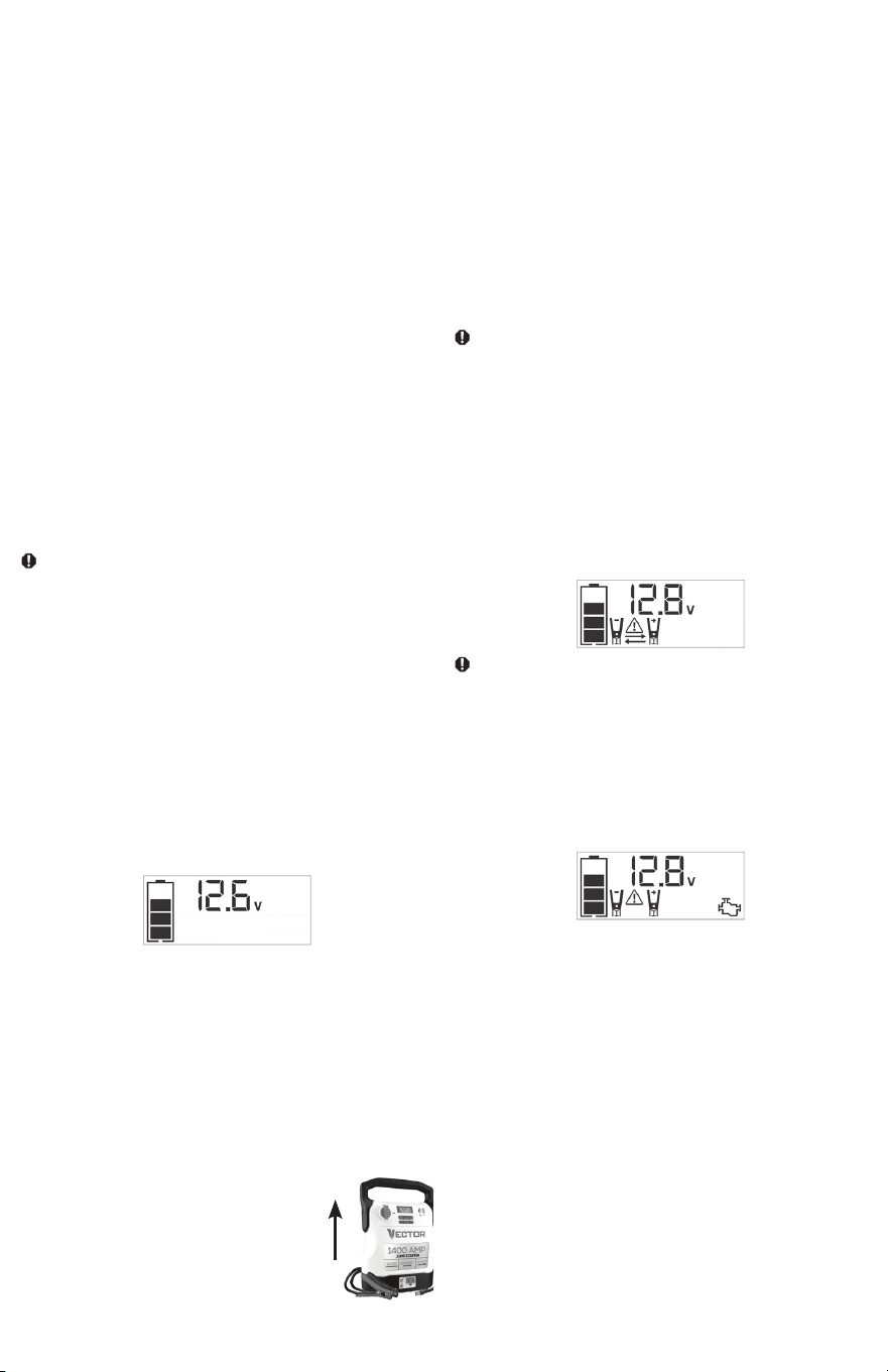
17
• Si la batería está casi agotada, aparecerá una barra sólida. La unidad
debe cargarse en este momento.
• Si la batería está completamente vacía, aparecerá el Ícono de Estado de
la Batería en blanco. La unidad DEBE cargarse en este momento o se
activará la protección de bajo voltaje incorporada en la unidad. La unidad
se apagará automáticamente y es posible que no funcione hasta que se
recargue la batería.
CARGAR/RECARGAR
Las baterías de plomo-ácido requieren un mantenimiento de rutina para
garantizar una carga completa y una larga vida útil. Todas las baterías
pierden energía por auto-descarga con el tiempo y más rápidamente
a temperaturas más altas. Por lo tanto, las baterías necesitan cargarse
periódicamente para reemplazar la energía perdida por la auto-descarga.
Cuando la unidad no estáen uso frecuente, el fabricante recomienda
recargar la batería al menos cada 30 días y después de cada uso.
IMPORTANTE: Si intenta utilizar la unidad cuando el nivel de carga de la
batería es demasiado bajo, la unidad se apagará automáticamente.
Recargue la unidad con todas las demás funciones apagadas lo antes
posible.
Notas:
Esta unidad se entrega parcialmente cargada; debe cargarla completamente
antes de usarla por primera vez. La carga de CA inicial debe durar
aproximadamente 30 horas o hasta que el Ícono de Estado de la Batería
muestre 4 barras sólidas.
Recargar la batería después de cada uso prolongará su vida útil; las
descargas intensas y frecuentes entre recargas y/o sobrecargas reducirán la
vida útil de la batería.
Asegúrese de que todas las demás funciones de la unidad estén apagadas
durante la recarga, ya que esto puede ralentizar el proceso de recarga.
PRECAUCIÓN – Riesgo de daños a la propiedad: si no se mantiene
la batería cargada, se producirán daños permanentes y se producirá un
rendimiento deficiente del arranque auxiliar.
IMPORTANTE: Si usted sabe que la unidad está descargada, pero el
Ícono de Batería muestra cuatro barras sólidas como si la unidad
estuviera completamente cargada cuando se conecta a una fuente de
alimentación de carga, esto puede deberse a que la batería interna tiene
alta impedancia. El fabricante sugiere dejar la unidad cargando durante
un período de 40 horas usando el cargador de CA suministrado antes de
usarla.
Carga/Recarga Utilizando el Cargador de CA Suministrado
1. Inserte el conector cilíndrico del cargador de CA en el Puerto de
Carga de CC de 12 voltios en la parte posterior de la unidad. Inserte
el extremo del enchufe en un tomacorriente (alimentado) estándar
norteamericano de 120 voltios y 60Hz. Cuando la unidad esté
conectada correctamente a una fuente de alimentación de CA, la
Pantalla LCD mostrará lo siguiente (la pantalla estará retroiluminada):
will be backlit):
Las barras en el Ícono de la Batería representan el nivel de capacidad
de la batería interna de la unidad. Después de 10 segundos, la luz de
fondo se apagará.
Las barras en el Ícono de la Batería cambiarán de vacías a sólidas (de
abajo hacia arriba) repetidamente para indicar que la unidad se está
cargando.
2. Cargue hasta que el Ícono de la Batería muestre 4 barras sólidas.
3. Cuando se complete la carga, desconecte el cargador de CA de la
unidad – primero desenchufe el cargador de la fuente de alimentación
de CA, luego desconecte el conector cilíndrico de la unidad.
ARRANCADOR AUXILIAR
IMPORTANTE: Todas las funciones deben estar apagadas
con excepción de la Luz de Área al realizar el arranque.
La unidad está diseñada para usarse únicamente en
posición vertical.
La unidad debe mantenerse en posición vertical
durante su uso. Vea la ilustración de la derecha
para conocer la orientación correcta.
Esta unidad está equipada con un Interruptor de Encendido de Arranque
Auxiliar que permite que la energía fluya solo cuando se realizan las
conexiones adecuadas a la batería y al bastidor.
1. Para sistemas con conexión a tierra negativa, conecte la Abrazadera
Positiva (Roja) al borne positivo de la batería sin conexión a tierra y
la Abrazadera Negativa (Negra) al chasis del vehículo o al bloque del
motor lejos de la batería. No conecte la abrazadera al carburador,
líneas de combustible o partes de la carrocería. Conéctela a una parte
metálica de gran calibre del bastidor o del bloque del motor.
2. Para sistemas con conexión a tierra positiva, conecte la Abrazadera
Negativa (Negra) al borne negativo de la batería sin conexión a tierra
y la Abrazadera Positiva (Roja) al chasis del vehículo o al bloque del
motor lejos de la batería. No conecte la abrazadera al carburador,
líneas de combustible o partes de la carrocería. Conéctela a una parte
metálica de gran calibre del bastidor o del bloque del motor.
IMPORTANTE: Asegúrese de que el compresor esté apagado antes de
intentar utilizar la unidad como Arrancador Auxiliar.
ADVERTENCIA – Para reducir el riesgo de lesiones graves o daños a
la propiedad:
• Siga todas las instrucciones de seguridad que se encuentran en la
sección “Instrucciones de Seguridad Específicas para Arrancadores
Auxiliares” de este Manual de Instrucciones.
• No permita que las abrazaderas roja y negra se toquen entre sí. Esto
puede provocar chispas peligrosas, arcos eléctricos y/o explosiones.
• Si las abrazaderas están conectadas incorrectamente con respecto a
la polaridad, la unidad hará sonar una alarma continua hasta que las
abrazaderas se desconecten. La pantalla LCD retroiluminada mostrará
el Ícono de Estado de la Batería, el Indicador de Voltaje de la Batería y
los Íconos de Abrazadera. Los signos “+” y “–” encima de los Íconos de
Abrazadera, los Íconos de Flecha y el Ícono de Alarma parpadearán. La
Pantalla LCD retroiluminada mostrará lo siguiente:
PRECAUCIÓN: La unidad sufrirá daños permanentes si el Interruptor
de Encendido del Arrancador se enciende mientras las abrazaderas están
conectadas con polaridad inversa. Desconecte las abrazaderas y vuelva a
conectarlas a la batería con la polaridad correcta.
• Si el Interruptor de Encendido del Arrancador Auxiliar está encendido y la
unidad detecta que las abrazaderas no están conectadas a una batería,
sonará una advertencia de dos segundos cada 10 segundos. La Pantalla
LCD mostrará el Ícono de Estado de la Batería, el Indicador de voltaje
de la Batería y los Íconos de Abrazadera con los signos “+” y “–”. El
Icono de Alarma y el Icono del Arrancador parpadearán. La Pantalla LCD
retroiluminada mostrará lo siguiente:
Apague el Interruptor de Encendido del Arrancador Auxiliar; conecte
las pinzas a la batería, asegurándose de que las abrazaderas estén
conectadas con la polaridad correcta; luego vuelva a encender el
Interruptor de Encendido del Arrancador.
• Siempre desconecte primero el cable negativo (negro), seguido del cable
positivo (rojo), excepto en los sistemas con conexión a tierra positiva.
Procedimiento
Siga los siguientes pasos, observando todas las precauciones y
advertencias en la sección “Instrucciones de Seguridad Importantes” al
principio de este manual.
1. Apague el encendido del vehículo y todos los accesorios (radio, aire
acondicionado, luces, cargadores de teléfonos celulares conectados, etc.).
Coloque el vehículo en “parking” y ponga el freno de emergencia.
2. Asegúrese de que el Interruptor de Encendido del Arrancador Auxiliar
esté en la posición APAGADO.
3. Retire las abrazaderas de las pestañas de las abrazaderas. Conecte
primero la abrazadera roja y luego la abrazadera negra.
4. Procedimiento para arranque auxiliar de un SISTEMA DE PUESTA A
TIERRA NEGATIVO (el terminal negativo de la batería está conectado al
chasis) (LO MÁS COMÚN).
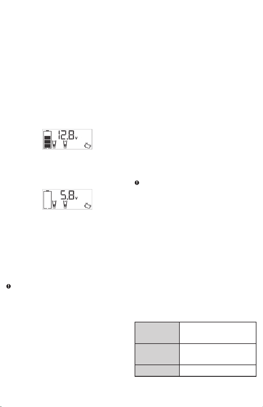
18
4a. Conecte la Abrazadera Roja Positiva (+) al borne positivo de la
batería del vehículo.
4b. Conecte la Abrazadera Negra Negativa (–) al chasis o a un
componente metálico sólido e inmóvil del vehículo o a una parte
de la carrocería. Nunca sujete directamente al terminal negativo de
la batería o a una pieza móvil. Consulte el manual del propietario
del automóvil.
5. Procedimiento para arranque auxiliar de SISTEMAS DE PUESTA A
TIERRA POSITIVO:
Nota:
En el raro caso de que el vehículo que se va a arrancar tenga un sistema
a tierra positivo (el terminal positivo de la batería está conectado al chasis),
reemplace los pasos 4a y 4b anteriores con los pasos 5a y 5b, luego continúe
con el paso 6.
5a. Conecte la Abrazadera Negra Negativa (–) al borne negativo de la
batería del vehículo.
5b. Conecte la Abrazadera Roja Positiva (+) al chasis del vehículo
o a un componente metálico sólido e inmóvil del vehículo o a
una parte de la carrocería. Nunca sujete directamente al borne
positivo de la batería o a una pieza móvil. Consulte el manual del
propietario del automóvil.
6. Cuando las abrazaderas estén conectadas correctamente, la Pantalla
LCD retroiluminada mostrará lo siguiente para indicar que la unidad está
lista para el arranque auxiliar:
El Ícono de Estado de la Batería, el Indicador de Voltaje de la Batería,
los Íconos de Abrazadera y los signos “+” y “–” se iluminan de
manera fija. El Icono del Arrancador parpadeará para indicar que las
abrazaderas están conectadas correctamente.
7. Gire el Interruptor de Encendido del Arrancador Auxiliar a ENCENDIDO.
Encienda e intente arrancar el motor en ráfagas de 5 a 6 segundos hasta
que arranque. La Pantalla LCD retroiluminada mostrará lo siguiente:
El Ícono de Estado de la Batería, el Indicador de Voltaje de la Batería,
los Íconos de Abrazadera y los signos “+” y “–” se iluminan de manera
fija para indicar que la unidad está auxiliando el arranque. El Icono del
Arrancador parpadea. El Icono del Arrancador se ilumina de forma fija
si arranca el vehículo.
8. Gire el Interruptor de Encendido del Arrancador Auxiliar a APAGADO.
9. Desconecte primero la Abrazadera Negativa (–) del motor o del chasis,
luego desconecte la Abrazadera Positiva (+) de la batería.
Nota: Si la unidad no funciona correctamente después del procedimiento
de arranque auxiliar, recárguela con el cargador de CA suministrado para
restablecerla.
IMPORTANTE: Apague siempre la unidad cuando no esté en uso. Recargue
esta unidad completamente después de cada uso.
PRECAUCIÓN – Para reducir el riesgo de daños a la propiedad:
• Los vehículos que tienen sistemas computarizados a bordo pueden sufrir
daños si se auxilia el arranque de la batería del vehículo. Antes de auxiliar
el arranque de este tipo de vehículo, lea el manual del vehículo para
confirmar que la asistencia de arranque externa es recomendada.
• El intento de arranque excesivo del motor puede dañar el motor de
arranque del vehículo. Si el motor no arranca después del número
recomendado de intentos, interrumpa el procedimiento de arranque
auxiliar y busque otros problemas que deban corregirse.
• Si el vehículo no arranca, apague el encendido, apague el Interruptor de
Encendido del Arrancador, desconecte los cables del sistema de arranque
y comuníquese con un técnico calificado para investigar por qué el motor
no arrancó.
LUZ DE ÁREA LED
La Luz de Área LED incorporada se controla mediante el Botón de
Encendido de la Luz de Área en el panel de control (consulte la sección
Funciones para ubicarla). Presione el Botón de Encendido de la Luz de
Área una vez para encender la luz. Presione el Botón de Encendido de la
Luz de Área nuevamente para apagar la Luz de Área.
IMPORTANTE: Cuando se presiona el Botón de Encendido de la Luz de
Área para encenderla, sonará un pitido. La Pantalla LCD retroiluminada
se encenderá durante 10 segundos (solamente) y luego mostrará
continuamente el Ícono de Estado de la Batería y el Indicador de Voltaje
de la Batería.
Verifique periódicamente el estado de la batería de la unidad en la Pantalla
LCD retroiluminada. Cuatro barras sólidas en el Ícono de la Batería indican
que la batería está llena. Cuando el nivel de la batería está casi vacío con
solo una barra sólida o el Ícono de Estado de Batería está vacío, la unidad
debe recargarse en este momento o se activará la protección de bajo
voltaje incorporada de la unidad. La unidad se apagará automáticamente
después de un breve período.
Asegúrese de que la Luz de Área esté apagada cuando la unidad se esté
recargando o esté almacenada.
FUENTE DE ENERGÍA PORTÁTIL DE 120 VOLTIOS CA
Consumo de Corriente Nominal Versus Real del Equipo
La mayoría de las herramientas eléctricas, aparatos, dispositivos
electrónicos y equipos audiovisuales tienen etiquetas que indican el
consumo de energía en amperios o vatios. Asegúrese de que el consumo
de energía del elemento que se va a utilizar sea inferior a 200 vatios. Si
el consumo de energía está clasificado en amperios CA, simplemente
multiplique por los voltios CA (120) para determinar el vatiaje.
Las cargas resistivas son las más fáciles de utilizar para esta unidad; sin
embargo, no funcionará con cargas resistivas más grandes (como estufas
y calentadores eléctricos), que requieren mucha más potencia de la que
la unidad puede generar de forma continua. Las cargas inductivas (como
televisores y equipos de música) requieren más corriente para funcionar
que las cargas resistivas del mismo vatiaje.
PRECAUCIÓN: Dispositivos recargables
• Ciertos dispositivos recargables están diseñados para cargarse
enchufándolos directamente a un receptáculo de CA. Estos dispositivos
pueden dañar el inversor o el circuito de carga.
• Cuando utilice un dispositivo recargable, controle su temperatura durante
los primeros diez minutos de uso para determinar si produce calor
excesivo.
• Si se produce calor excesivo, esto indica que el dispositivo no debe
usarse con este inversor.
• Este problema no ocurre con la mayoría de los equipos que funcionan
con baterías. La mayoría de estos dispositivos utilizan un cargador o
transformador independiente que se conecta a un receptáculo de CA.
• El inversor es capaz de hacer funcionar la mayoría de los cargadores y
transformadores.
Nota: Es posible que algunas computadoras portátiles no funcionen con
este inverso.
Forma de Onda de Salida del Inversor de Potencia
La forma de onda de salida de CA de este inversor se conoce como
onda sinusoidal modificada. Es una forma de onda escalonada que
tiene características similares a la forma de onda sinusoidal de la energía
eléctrica. Este tipo de forma de onda es adecuado para la mayoría de las
cargas de CA, incluidas las fuentes de alimentación lineales y conmutadas
utilizadas en equipos electrónicos, transformadores y motores pequeños.
Características de Protección
El inversor monitorea las siguientes condiciones:
Bajo voltaje de la
batería interna
El inversor se apagará automáticamente
cuando el voltaje de la batería baje
demasiado, ya que esto puede dañar la
batería.
Alto voltaje de la batería
interna
El inversor se apagará automáticamente
cuando el voltaje de la batería sea
demasiado alto, ya que esto puede dañar
la unidad.
Protección de apagado
térmico
El inversor se apagará automáticamente
cuando la unidad se sobrecaliente.
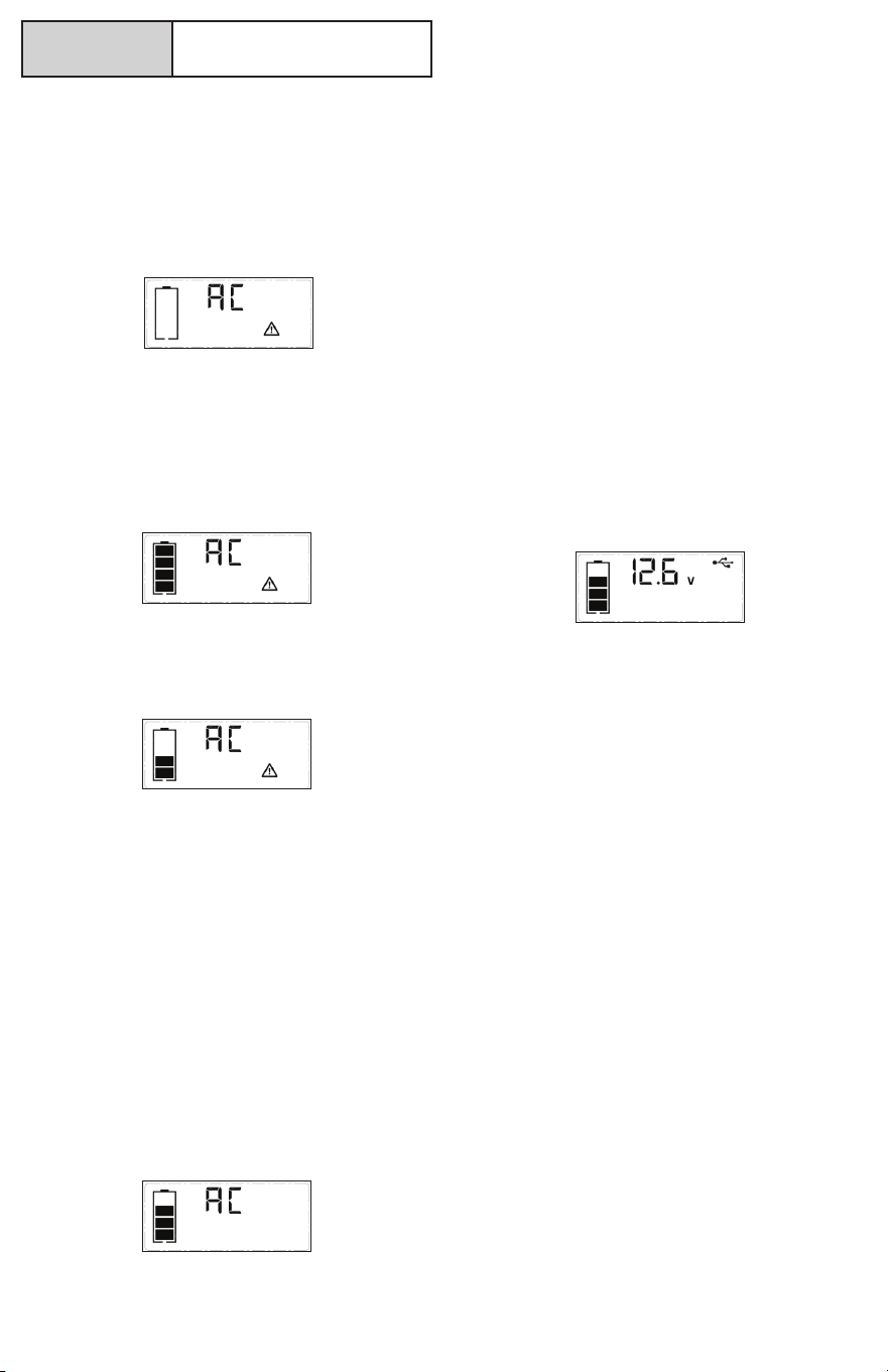
19
Protección contra
sobrecarga/
cortocircuito
El inversor se apagará automáticamente
cuando se produzca una sobrecarga o un
cortocircuito.
NOTAS IMPORTANTES:
El Tomacorriente de CA proporciona un consumo total de energía de
200W.
Cuando el Tomacorriente de CA esté en uso, la unidad monitoreará las
siguientes condiciones de falla: falla térmica, falla de voltaje alto y bajo de
la batería, sobrecarga y cortocircuito (consulte la sección “Características
de Protección”).
1. Si existe una condición de falla de bajo voltaje de la batería interna, el
Tomacorriente de CA se apagará automáticamente y la Pantalla LCD
retroiluminada mostrará lo siguiente hasta que se corrija la falla:
La Pantalla Digital mostrará “AC”; el Ícono de Estado de Batería
VACÍA y el Ícono de Falla en la Pantalla LCD parpadearán durante
60 segundos. Después de 60 segundos, la Pantalla Digital mostrará
el Indicador de Voltaje de la Batería, el Ícono de Estado de Batería
VACÍA y el Ícono de Falla en la Pantalla LCD parpadearán durante 10
segundos antes de que la unidad se apague automáticamente.
2. Si existe una condición de falla de alto voltaje de la batería interna, el
Tomacorriente de CA se apagará automáticamente y la Pantalla LCD
retroiluminada mostrará lo siguiente hasta que se corrija la falla:
La Pantalla Digital mostrará “AC”; el Ícono de Estado de Batería
COMPLETA y el Ícono de Falla en la Pantalla LCD parpadearán.
3. Si existe una condición de falla térmica, de sobrecarga o de
cortocircuito, el Tomacorriente de CA se apagará automáticamente
y la Pantalla LCD retroiluminada mostrará lo siguiente hasta que se
corrija la falla:
4. El Icono de Estado de la Batería se iluminará de forma fija; “AC” en la
Pantalla Digital y el Ícono de Falla en la Pantalla LCD parpadearán.
Si ocurre alguna de las condiciones de falla anteriores:
1. Desconecte el aparato de la unidad.
2. Presione el Botón de Encendido de CA para apagar el Tomacorriente
de CA.
3. Asegúrese de que no sea necesario recargar la unidad.
4. Deje que la unidad se enfríe durante varios minutos.
5. Asegúrese de que la potencia del aparato conectado a la unidad sea
de 200 vatios o menos y que el cable y el enchufe del aparato no
estén dañados.
6. Asegúrese de que haya ventilación adecuada alrededor de la unidad
antes de continuar.
Uso del Tomacorriente de CA de 120 Voltios
El Tomacorriente de 120 voltios CA está ubicado en el frente de la unidad.
El Tomacorriente admite un consumo máximo de energía de 200 vatios.
1. Presione el Botón de Encendido de CA para encender el Tomacorriente
de CA de 120V. Sonará un pitido y la Pantalla LCD mostrará lo
siguiente:
El Icono de Estado de la Batería se ilumina de forma fija y la Pantalla
Digital muestra el Icono “CA”, lo que indica que el Tomacorriente de
CA está listo para usar.
2. Inserte el enchufe de 120 voltios de CA del aparato en el Tomacorriente
de 120 voltios de CA.
3. Encienda el aparato y opere como de costumbre.
Nota: Asegúrese de que la potencia del equipo enchufado al
Tomacorriente de CA de 120V no exceda los 200 vatios
continuos.
4. Presione nuevamente el Botón de Encendido de CA para apagar el
Tomacorriente de CA de 120V.
Verifique periódicamente el estado de la batería de la unidad en la pantalla
LCD retroiluminada. Cuatro barras sólidas en el Ícono de la Batería indican
que la batería está llena. Cuando el nivel de la batería está casi vacío con
solo una barra sólida o un Ícono de Estado de Batería vacío, la unidad
debe recargarse en este momento o se activará la protección de bajo
voltaje incorporada de la unidad. El Icono de Estado de la Batería vacía
parpadeará durante un breve periodo de tiempo antes de que se apague
automáticamente.
IMPORTANTE:
• Asegúrese de que el Tomacorriente de CA esté apagado cuando la
unidad se esté recargando o esté almacenada.
• El inversor se apagará automáticamente cuando la unidad cambie al
modo de carga/recarga.
PUERTOS DE CARGA USB
El Botón de Encendido USB y los dos Puertos USB están ubicados en la
parte frontal de la unidad.
1. Presione el Botón de Encendido USB para encender los Puertos
USB. Sonará un pitido y la Pantalla LCD retroiluminada mostrará
continuamente lo siguiente:
El Ícono de Estado de la Batería y el Indicador de Voltaje de la Batería
se iluminarán de manera fija, así como el Ícono USB, lo que indica que
los Puertos USB están listos para usar.
2. Conecte el dispositivo o los dispositivos alimentado(s) por USB a los
Puertos de Alimentación USB y opere normalmente.
Presione el Botón de Encendido USB nuevamente para apagar los
Puertos USB. Asegúrese de que los Puertos USB estén apagados cuando
la unidad se esté recargando o esté almacenada.
NOTAS IMPORTANTES:
El Puerto USB-A proporciona hasta 15W de potencia de salida. El Puerto
USB-C proporciona hasta 25W de potencia de salida PD. La salida total
es de hasta 5V/15W cuando se utilizan USB-C y USB-A simultáneamente.
Cuando los Puertos USB estén en uso, la unidad monitoreará las
siguientes condiciones de falla USB en los Puertos USB: falla de voltaje
de batería baja, sobrecarga y cortocircuito.
Si existe una condición de falla de bajo voltaje de la batería interna, la
Pantalla Digital mostrará el Indicador de Voltaje de la Batería, el Ícono
de Estado de la Batería VACÍA y el Ícono de Falla en la Pantalla LCD
parpadearán durante 10 segundos antes de que la unidad se apague
automáticamente.
Si existe una condición de falla por sobrecarga o cortocircuito, los Puertos
USB se apagarán automáticamente.
Si esto ocurriera:
• Desconecte el dispositivo alimentado por USB y presione el Botón de
Encendido USB nuevamente para apagarlo inmediatamente.
• Asegúrese de que no sea necesario recargar la unidad.
• Deje que la unidad se enfríe durante varios minutos antes de intentar
utilizar los Puertos USB nuevamente.
• Si vuelve a ocurrir una falla, asegúrese de que el consumo total de los
dispositivos USB conectados a los Puertos USB no exceda el rango
máximo.
• Si el dispositivo USB individual está dentro de las especificaciones y se
produce la falla, haga que revisen el dispositivo USB para ver si funciona
mal y no continúe usándolo con los Puertos USB.
Verifique periódicamente el Estado de la Batería de la unidad en la Pantalla
LCD retroiluminada. Cuatro barras sólidas en el Ícono de la Batería indican
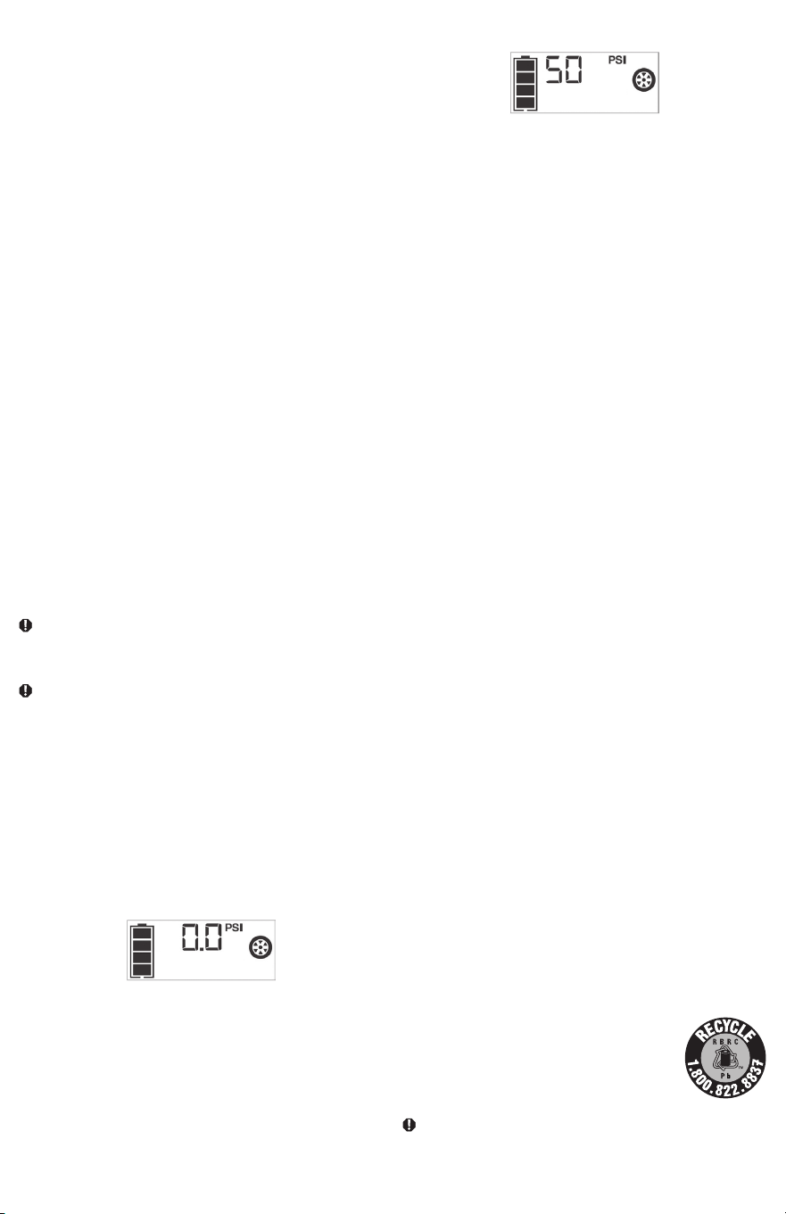
20
que la batería está llena. Cuando el nivel de la batería está casi vacío con
solo una barra sólida o un Ícono de Estado de la Batería vacío, la unidad
debe recargarse en este momento o se activará la protección de bajo
voltaje incorporada de la unidad. El Icono de Estado de la Batería vacía
parpadeará durante un breve periodo de tiempo antes de que se apague
automáticamente.
Notas:
• Los Puertos de Alimentación USB de esta unidad no admiten
comunicación de datos. Solo proporcionan energía a dispositivos
externos alimentados por USB.
• Algunos aparatos electrónicos domésticos alimentados por USB no
funcionarán con esta unidad.
COMPRESOR PORTÁTIL
El compresor incorporado de CC de 12 voltios es lo último en
compresores para neumáticos de vehículos, neumáticos de remolques
e inflables recreativos. Se suministra un adaptador de boquilla que se
atornilla al extremo de la boquilla Sure Fit® en el extremo libre de la
manguera del compresor. La manguera del compresor con conector para
neumáticos se guarda en el compartimento de almacenamiento. Consulte
la ilustración “Características” para conocer la ubicación de la manguera
del compresor. El Botón de Encendido del Compresor y los Botones de
Control de Presión del Compresor para aumentar (+) y disminuir (–) están
ubicados en el panel de control en la parte frontal de la unidad.
Antes de continuar, verifique el Estado de la Batería de la unidad en la
Pantalla LCD. Cuatro barras sólidas en el Ícono de la Batería indican que
la batería está llena. Cuando el nivel de la batería está casi vacío con solo
una barra sólida, la unidad DEBE recargarse antes de usarla o se activará
la protección de bajo voltaje incorporada de la unidad. El Icono de Estado
de la Batería vacía parpadeará durante un breve periodo de tiempo antes
de que se apague automáticamente.
El compresor es capaz de inflar hasta 120 libras por pulgada cuadrada
(PSI). El compresor puede funcionar el tiempo suficiente para llenar hasta
3 neumáticos de tamaño medio antes de que sea necesario recargar
la batería. Devuelva la manguera al compartimento de almacenamiento
después de su uso.
IMPORTANTE: Asegúrese de que el Interruptor de Encendido del Arrancador
Auxiliar esté apagado antes de intentar usar la unidad como Compresor.
ADVERTENCIA – Para reducir el riesgo de lesiones graves o daños
a la propiedad: Siga todas las instrucciones de seguridad que se
encuentran en la sección “Instrucciones de Seguridad Específicas para
Compresores” de este manual de instrucciones.
PRECAUCIÓN – para reducir el riesgo de lesiones graves o daños
a la propiedad: No haga funcionar el compresor de forma continua
durante más de 10 minutos, ya que podría sobrecalentarse. Esto podría
dañar el compresor. Si el compresor debe funcionar durante períodos
más prolongados: cada 10 minutos presione el Botón de Encendido
del Compresor para apagarlo y luego reinícielo después de un período
de enfriamiento de aproximadamente 30 minutos. En cualquier caso,
el compresor se apagará automáticamente después de funcionar
continuamente durante 10 minutos.
Inflar Neumáticos o Productos con Vástagos de Válvula
1. Enrosque la boquilla Sure Fit® en el vástago de la válvula. No apriete
demasiado.
2. Presione el Botón de Encendido del Compresor. Sonará un pitido y la
Pantalla LCD retroiluminada mostrará lo siguiente:
El Ícono del Compresor se iluminará y la Pantalla Digital mostrará
alternativamente el valor de PSI preestablecido parpadeante (que fue
configurado por última vez con los botones de control de presión del
compresor) y la presión actual del artículo que se está inflando (que se
iluminará fijamente).
3. Presione los Botones de Control de Presión “+” y “–” para establecer
la presión deseada a partir de un rango de valores preestablecidos
(entre 3 y 120), que se mostrará en la Pantalla LCD retroiluminada. La
unidad emitirá un pitido cada vez que presione los botones (mantener
presionado el botón acelera la selección de valores hacia arriba o hacia
abajo). Una vez que se haya ingresado la presión deseada, suelte
el botón y la pantalla digital parpadeante mostrará la nueva presión
seleccionada, de la siguiente manera:
El nuevo valor seleccionado ahora se almacena en la memoria de la
unidad hasta que se reinicie manualmente.
4. Presione el Botón de Encendido del Compresor una vez más para
comenzar a inflar. El Icono del Compresor parpadeará y la pantalla
digital solo mostrará el valor de presión actual (que se iluminará de
forma fija) para indicar que el compresor está activado. Controle la
presión en la Pantalla LCD.
Nota Importante: Para interrumpir durante el inflado, presione
nuevamente el Botón de Encendido del Compresor.
5. Cuando se alcance la presión preestablecida deseada, el compresor se
detendrá automáticamente.
6. Presione nuevamente el Botón de Encendido del Compresor para
apagar la unidad.
7. Desenrosque y retire la boquilla Sure Fit® del vástago de la válvula.
8. Deje que la unidad se enfríe y luego recárguela antes de guardarla.
9. Guarde la manguera del compresor y la boquilla Sure Fit® en el
compartimiento de almacenamiento.
Inflar Otros Inflables sin Vástagos de Válvula
El inflado de otros artículos requiere el uso del adaptador de boquilla.
1. Atornille el adaptador de la boquilla en la boquilla Sure Fit®. No apriete
demasiado.
2. Inserte el adaptador de boquilla en el artículo que desea inflar.
3. Siga los pasos 2 a 4 de la sección “Inflado de Neumáticos o Productos
con Vástagos de Válvula”.
IMPORTANTE: Los artículos pequeños como pelotas de voleibol, balones
de fútbol, etc. se inflan muy rápidamente. Tenga esto en cuenta al
ajustar la presión. Tenga especial cuidado de no inflar demasiado.
4. Cuando se alcance la presión deseada, el compresor se detendrá
automáticamente. Presione nuevamente el Botón de Encendido del
Compresor para apagar la unidad.
5. Desconecte el adaptador del artículo inflado.
6. Desenrosque y retire el adaptador de la boquilla Sure Fit®.
7. Deje que la unidad se enfríe y luego recárguela antes de guardarla.
8. Guarde la manguera del compresor, la boquilla Sure Fit® y el
adaptador de boquilla en el compartimiento de almacenamiento.
CUIDADO Y MANTENIMIENTO
Todas las baterías pierden energía por auto-descarga con el tiempo y más
rápidamente a temperaturas más altas. Cuando la unidad no esté en uso,
recomendamos cargar la batería al menos cada 30 días.
Nunca sumerja la unidad en agua. Si la unidad se ensucia, limpie
suavemente las superficies exteriores de la unidad con un paño suave.
No hay piezas reemplazables por el usuario. Inspeccione periódicamente
el estado de adaptadores, conectores y cables.
BATERÍA
Tenga en cuenta que la batería está diseñada para durar toda la vida útil de
la unidad y no es reemplazable, extraíble ni reparable. La vida útil depende
de una serie de factores que incluyen, entre otros, el número de ciclos de
recarga y el cuidado y mantenimiento adecuados de la batería por parte
del usuario final. Póngase en contacto con el fabricante para cualquier
información que pueda necesitar.
ELIMINACIÓN SEGURA DE LA BATERÍA
Contiene una batería de plomo-ácido, sellada y a prueba
de derrames, que no requiere mantenimiento y que debe
desecharse adecuadamente. Se requiere reciclaje. El
incumplimiento de las regulaciones locales, estatales y
federales puede resultar en multas o prisión.
Por favor recicle.
ADVERTENCIAS:
• No arroje la batería al fuego, ya que esto podría provocar una explosión.

21
• Antes de desechar la batería, proteja los terminales expuestos
con cinta aislante resistente para evitar cortocircuitos (los cortocircuitos
pueden provocar lesiones o incendios).
• No exponga la batería al fuego ni al calor intenso, ya que podría explotar.
SOLUCIÓN DE PROBLEMAS
La unidad no carga
• Asegúrese de que se haya presionado el Botón de Encendido de CA para
apagar el inversor.
• Asegúrese de que un cable de extensión de calibre adecuado esté
conectado correctamente tanto a la unidad como a un tomacorriente de
CA que funcione.
La unidad no logra auxiliar el arranque
• Asegúrese de que la unidad no esté funcionando en el modo Compresor.
• Asegúrese de que el Interruptor de Encendido del Arrancador Auxiliar de
la unidad esté en la posición de encendido.
• Asegúrese de que se haya establecido una conexión de cable con la
polaridad adecuada.
• Verifique que la unidad tenga carga completa. Recargue la unidad si es
necesario.
El tomacorriente de CA de 120 voltios no alimenta el aparato
• Asegúrese de que se haya presionado el Botón de Encendido de CA para
encender el inversor.
• Asegúrese de que la unidad no esté en modo de carga/recarga.
• Asegúrese de haber seguido cuidadosamente todos los pasos de las
instrucciones de la fuente de alimentación portátil de 120 CA.
• Asegúrese de que el aparato que se está alimentando no consuma más
de 200 vatios.
• Consulte las notas importantes incluidas en esa sección que explican
problemas y soluciones comunes.
• Verifique que la unidad tenga carga completa. Recargue la unidad si es
necesario.
El Puerto de Alimentación USB no alimenta el aparato
• Asegúrese de que el dispositivo USB conectado al Puerto USB-A no
supere los 15W; el dispositivo USB conectado al Puerto USB-C no supera
los 25W PD; o la potencia total consumida del Puerto USB-A y el Puerto
USB-C no supera los 15W cuando se utilizan simultáneamente.
• Asegúrese de que se haya presionado el Botón de Encendido USB para
encender los Puertos USB.
• Algunos aparatos electrónicos domésticos alimentados por USB no
funcionarán con estos Puertos USB. Consulte el manual del dispositivo
electrónico correspondiente para confirmar que se puede utilizar con este
tipo de Puertos USB.
• Verifique que la unidad tenga carga completa. Recargue la unidad si es
necesario.
La Luz de Área LED no se enciende
• Asegúrese de que se haya presionado el Botón de Encendido de la Luz
de Área para encender la Luz de Área.
• Verifique que la unidad tenga carga completa. Recargue la unidad si es
necesario.
El compresor portátil no infla
• Asegúrese de que la unidad no esté funcionando en el modo de
Arrancador Auxiliar.
• Asegúrese de que se haya presionado el Botón de Encendido del
Compresor para encender el compresor.
• Asegúrese de que el conector de la boquilla Sure Fit® esté bien
atornillado al vástago de la válvula cuando intente inflar neumáticos; o que
el adaptador de la boquilla esté firmemente atornillado al conector de la
boquilla Sure Fit® y esté insertado correctamente en el artículo o todos
los artículos que se vayan a inflar.
• El compresor puede estar sobrecalentado. Presione el Botón de
Encendido del Compresor para apagarlo. Reinicie después de un período
de enfriamiento de aproximadamente 30 minutos.
• Verifique que la unidad tenga carga completa. Recargue la unidad si es
necesario.
ACCESORIOS
Los accesorios recomendados para usar con su herramienta pueden estar
disponibles del fabricante. Si necesita ayuda con respecto a los accesorios,
comuníquese con el fabricante al (877) 571-2391.
ADVERTENCIA: El uso de cualquier accesorio no recomendado para
este aparato podría ser peligroso.
ASISTENCIA TÉCNICA
Para Servicio al Cliente o Asistencia Técnica, comuníquese con el
fabricante al 1-877-571-2391.
GARANTÍA LIMITADA DEL FABRICANTE DE UN AÑO
El fabricante, Baccus Global LLC, garantiza este producto contra defectos
de materiales y mano de obra por un período de UN (1) AÑO a partir de la
fecha de compra minorista por parte del comprador usuario final original
o desde la fecha de entrega del bien, cualquiera que sea que ocurra más
tarde (“Período de Garantía”).
Si hay un defecto y el fabricante recibe un reclamo válido dentro del
Período de Garantía, el producto defectuoso se puede reemplazar de
las siguientes maneras: (1) Devolver el producto al fabricante para su
reemplazo. Es posible que el fabricante solicite un comprobante de
compra. (2) Devolver el producto al minorista donde lo compró para
un cambio (siempre que la tienda sea un minorista participante). Las
devoluciones al minorista deben realizarse dentro del período de tiempo
de la política de devolución del minorista para cambios únicamente. Es
posible que se requiera prueba de compra. Consulte con el minorista su
política de devolución específica con respecto a las devoluciones que
superan el tiempo establecido para los cambios.
La garantía de este fabricante no se aplica a accesorios, bombillas,
fusibles y baterías; defectos resultantes del desgaste normal, accidentes;
daños sufridos durante el envío; alteraciones; uso no autorizado;
negligencia, mal uso, abuso; y el incumplimiento de las instrucciones de
cuidado y mantenimiento del producto.
Esta garantía del fabricante le otorga a usted, el comprador minorista
original, derechos legales específicos y usted puede tener otros derechos
que varían de un estado a otro o de una provincia a otra. Este producto
no está diseñado para uso comercial. Para registrar su producto con el
fabricante, visite www.BaccusGlobal.com.
Las fotografías de este manual pueden diferir de la unidad real.
ESPECIFICACIONES
Amperaje de Refuerzo: batería máxima de 1.400A
Tipo de batería: Ácido de plomo sellado, libre de
mantenimiento, 12V CC
Entrada de CA: 14.5VDC, 800mA
Salida USB-C: 5VDC 3A / 9VDC 2.77A (PD
25W máx.)
Salida USB-A: 5VDC, 15W máx.
Salida USB-C y USB-A simultáneamente: 5VDC, 15W máx.
Tomacorriente de 120 VCA: 120V AC, 60Hz, 200W
continua
Importado por Baccus Global LLC,
225 NE Mizner Blvd., Suite 301, Boca Raton, FL 33432
www.Baccusglobal.com 1-877-571-2391
RD051424

22

23