Operating, Service and
Warranty Manual
ENERGY EFFICIENT REFRIGERATED AIR DRYERS
Flexzilla® designs and manufactures products for safe operaon. However, operators and maintenance persons are
responsible for maintaining safety. All safety precauons are included to provide a guideline for minimizing the
possibility of accidents and property damage while equipment is in operaon. Keep these instrucons for reference.
2211
Scan or go to website hosted below:
www.eatoncompressor.com/warranty
Warranty only valid by following conditions expressed in the Warranty Statement section of this Air Dryer Manual.
2
Flexzilla Pro Energy Ecient Refrigerated Air Dryers
Scan or go to website hosted below:
www.eatoncompressor.com/warranty
Warranty only valid by following conditions expressed in the Warranty Statement section of this Air Dryer Manual.
Contents
1. Important Safety Notes - Please read ......................3
1.1 Transportation ..............................................................3
1.2 Positioning ............................................................3
1.3 Installation ............................................................3
1.4 Before Operating ..................................................3
1.5 Qualified Service Personnel .................................3
1.6 Maintenance By The User ....................................4
2. Introduction To The Dryer ..........................................4
3. Operation ....................................................................4
4. Electrical Controller ...................................................7
4.1 Digi-Pro ................................................................7
4.2 ESD 3 ...................................................................8
5. Technical Specifications .........................................12
6. Diagrams ..................................................................12
6.1 Air Flow Diagrams ..............................................12
6.2 Electrical Diagrams ............................................14
7. ID Diagram Drawings ...............................................16
General Arrangements ..............................................18
8. Exploded Diagrams .................................................18
9. Components Location .............................................22
10. Troubleshooting .......................................................23
11. Warranty ...................................................................26
Scan or go to website hosted below:
www.eatoncompressor.com/warranty
Warranty only valid by following conditions expressed in the Warranty Statement section of this Air Dryer Manual.
YOU MUST
REGISTER TO
ACTIVATE
WARRANTY
3
Flexzilla Pro Energy Ecient Refrigerated Air Dryers
3
1. IMPORTANT SAFETY NOTES
When operang the air dryer the operator must apply
safe working methods and observe all local safety
instrucons and relevant regulaons.
A) Prior to installaon, the dryer and the compressed
air system are to be depressurized and
disconnected from the electrical main supply.
B) The user is responsible for safe operang
condions. Parts and accessories must be replaced
if inspecon shows that safe operaon cannot be
assured.
C) Installaon, operaon, maintenance and repair
are only to be performed by authorized, trained
and skilled technicians.
D) The minimum and maximum values stated must
be followed, as well as all of the safety precauons
described in this manual.
E) If any statement in this manual does not comply
with the local code laws, the strongest standard is
to be applied.
1.1. Transportaon
A) Use care and cauon when transporng the dryer.
Avoid dropping and other physical abuse.
B) A forkli can be used to transport the dryers
provided the forks are long enough to support its
full width or length and cauon is used throughout
the move.
1.2. Posioning
A) The dryer must be installed horizontally. A
minimum of 20 in. clearance around the dryer is
necessary to allow good venlaon and easy
access for servicing.
B) The ambient temperature in the room should not
exceed 113°F and should not be below 39.2°F, also
taking the heat radiated by the dryer into account.
C) (40 wa for each liter/sec under ISO 7138-A
condion or 18 was for each SCFM under ISO
7183-B condion).
D) There should be no chemicals in the atmosphere
that will damage the copper source. (Ammonia
gas, etc.)
1.3 Installaon
In addion to the general mechanical construcon
procedures and local code regulaons, the following
instrucons need to be understood and followed:
1) Only authorized, trained and skilled technicians
should install the compressed air dryer.
2) Safety devices, protecng covers or insulaon in
the dryers are never to be dismantled or modied.
Each pressure vessel or accessory installed outside
the dryer with air above atmospheric pressure
must be ed with the required pressure relief
safety valves.
1.4 Before Operang
The following must be observed before operang the
air dryer:
A) Review all safety precauons.
B) The dryer connecon piping measurements must
be selected correctly. (See Technical Specicaons)
C) The dryer connecon piping must be adapted to
the operang pressure. (See Technical
Specicaons)
D) Never operate the dryer at pressure above the
maximum specied on the dryer label (See
Technical Specicaons)
E) The drains should be opened to atmosphere. If the
drains are connected to a pipe/hose, the diameter
of the pipe/hose should be large enough to
create no back pressure during draining. It is not
recommended to reduce the diameter of the pipe/
hose less than the port that is given at the
drain outlet of the unit. The pipe/hose should be
at atmospheric pressure at all me. Back pressure
in relevant pipe will result in permanent damage
on drain system and funcon of the lters and/or
dryers.
1.5 Qualied Service Technicians
A) Maintenance and repairs should only be
performed when the air dryer is shut down,
depressurized and when the main power switch
is turned o. Lock and tag out of the power supply
is recommended.
B) Only use the appropriate tools for maintenance
and repair.
C) Before dismantling a part under pressure,
disconnect the pressure sources and depressurize
the system.
Scan or go to website hosted below:
www.eatoncompressor.com/warranty
Warranty only valid by following conditions expressed in the Warranty Statement section of this Air Dryer Manual.
YOU MUST
REGISTER TO
ACTIVATE
WARRANTY
Flexzilla Pro Energy Ecient Refrigerated Air Dryers
4
D) Proceed carefully during maintenance and repair.
Prevent dirt from entering by covering parts and
orices with a clean cloth, paper or tape. A
receiver should never be welded or modied in
any way.
E) Never leave tools, loose parts or cleaning rags in or
on the air dryer.
F) Before pung the dryer into service, check the
sengs of the control and safety devices as well as
the pressure and temperature of the compressed
air circuit.
1.6 Maintenance By The User
A) Keep the dryer clean.
B) Regularly check the correct operaon of the
condensate drain water trap.
C) Ever six months, check and clean the drain strainer
by undoing the access screw and rinsing the lter
with tap water to remove the trapped dirt from
the inside.
D) For air cooled dryers, clean the air condenser as
soon as it’s dirty or clogged.
E) For oponal water-cooled condensers, use only
clean water and install a water lter if needed. Use
proper water treatment if calcium levels are high.
F) Check the trouble-shoong list in case of
maintenance problems.
G) Check operang pressures, temperatures and me
sengs aer maintenance. If operang and safety
devices funcon properly, the air dryer may be
used.
2. INTRODUCTION TO THE DRYER
A) Purpose of this dryer
1) This refrigerated compressed air dryer has been
designed to remove water vapor from the
industrial compressed air system.
2) This dryer has been designed for indoor operaon.
3) The minimum and maximum values stated must be
observed, as well as the safety precauons
described in this manual.
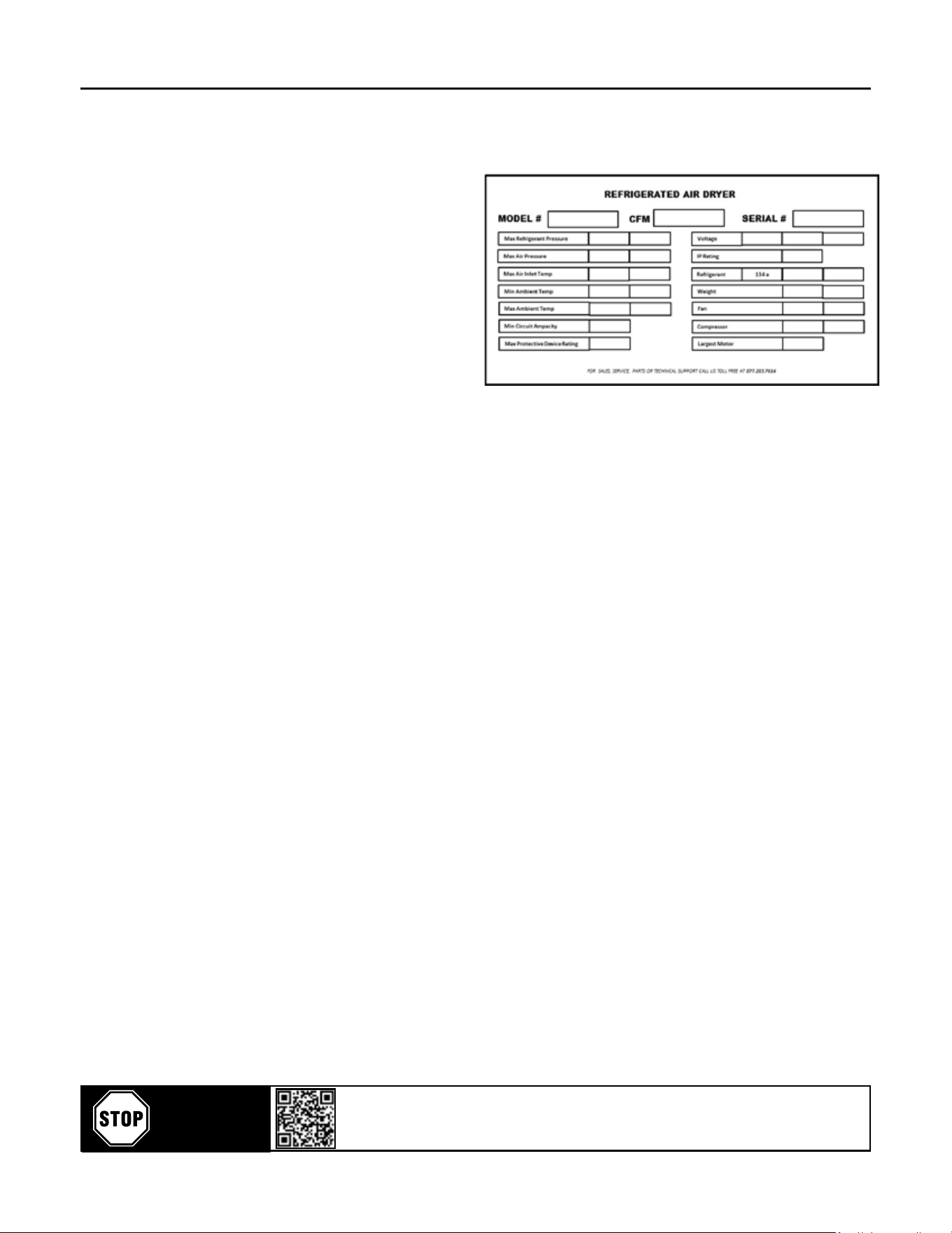
B) Dryer label
The following label is axed on the cabinet of the
refrigerant compressed air dryer.
C) Working details
1) Refrigerant circuit:
The refrigerant circuit can be divided into 3 parts:
A) Low pressure secon with an evaporator
(heat exchanger)
B) High-pressure secon including: Condenser, liquid
receiver (if installed) and the lter dryer.
C) Control circuit including: compressor, expansion
valve, by-pass valve (if installed), fan pressure
switch (if installed)
2) The refrigerant circuit operates as follows:
A) The compressor compresses gaseous refrigerant to
a high temperature.
B) The hot refrigerant condenses in the condenser.
Being liqueed it is stored in the liquid receiver
(if installed).
C) The liquid is taken out of the storage vessel and
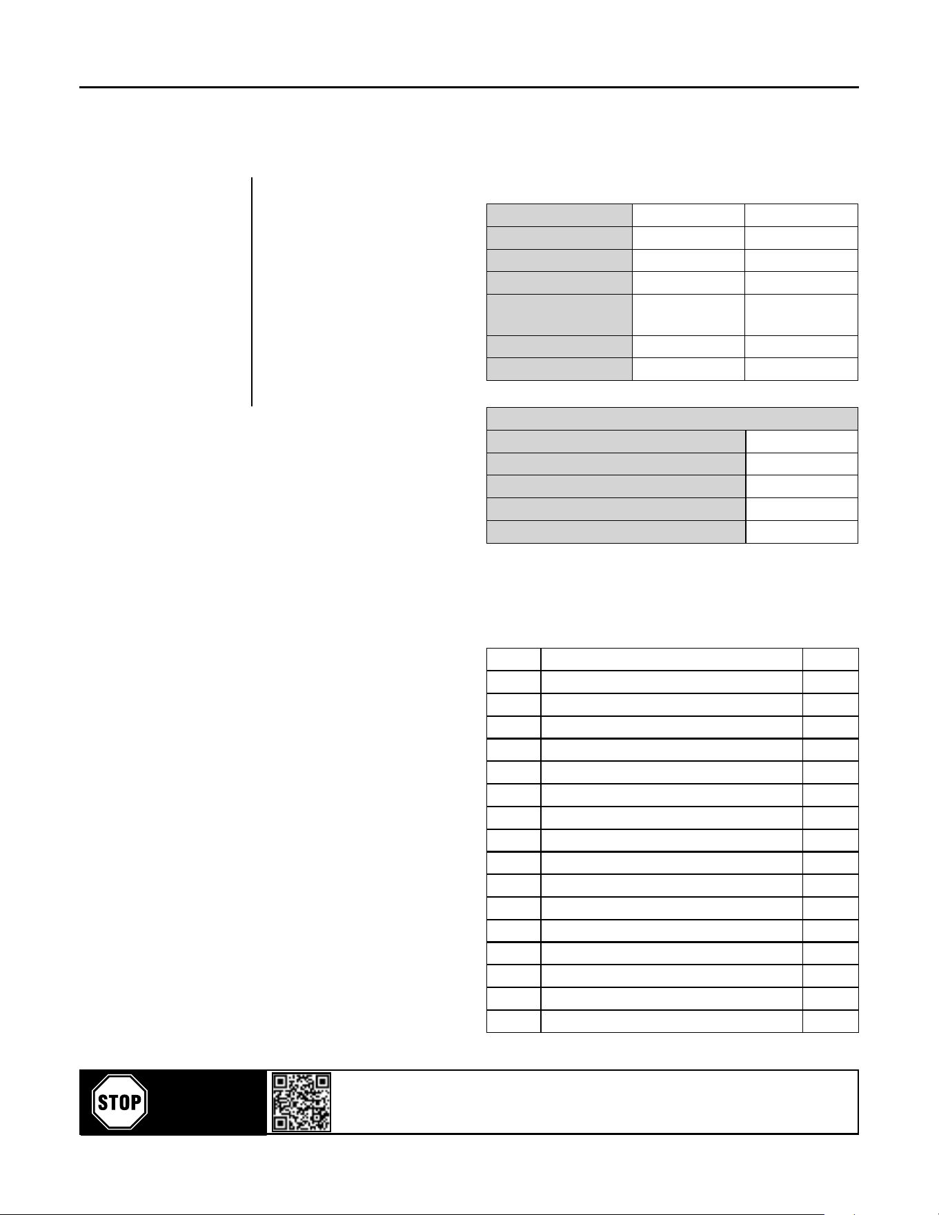
Dryer Label Descripons:
Model #: Dryer Model No.
CFM: Cubic feet per minute
Serial #: Dryer Serial No.
Max. Refrigerant Pressure: Dryer maximum working pressure
Max. Air Pressure: Maximum air pressure
Max. Air Inlet Temp.: Maximum air inlet temperature
Min. Ambient Temp.: Minimum ambient temperature
Max. Ambient Temp.: Maximum ambient temperature
Min. Circuit Ampacity: Minimum circuit ampacity
Max. Protecve Device Rang: Maximum protecve device rang
Voltage: Main supply voltage
IP Rang: Protecon rang
Refrigerant 134a: Amount of refrigerant gas used
Weight: Dryer weight
Fan: Model of fan used
Compressor: Model of compressor used
Largest Motor: Model of dryer motor used
Scan or go to website hosted below:
www.eatoncompressor.com/warranty
Warranty only valid by following conditions expressed in the Warranty Statement section of this Air Dryer Manual.
YOU MUST
REGISTER TO
ACTIVATE
WARRANTY
Flexzilla Pro Energy Ecient Refrigerated Air Dryers
5
injected in the evaporator (heat exchanger) by an
expansion valve. This expansion valve is protected
by a lter, which removes parcles and humidity
that could be in the circuit.
D) The injected liquid lls in the refrigerant secon of
the air/refrigerant heat exchanger and evaporates
by taking out the humidity from the compressed
air. The gaseous refrigerant is sucked in the
compressor and the cycle carries on.
E) In order to keep the evaporaon pressure
steady, and the refrigerant temperature in the
heat exchanger, a by-pass valve is injecng hot
gaseous refrigerant in the circuit. On certain dryers,
an automac expansion valve regulates the
amount of refrigerant.
3) Compressed air circuit
A) The saturated hot compressed air ows into the
economizer where it is pre-cooled by the out
owing dry chilled air. In the cold operang
condions the air refrigerant secon connues
to cool down to dew point and enters the
separator where condensates are collected.
The outgoing chilled air is then warmed up in the
economizer by the hot incoming air. This eliminates
condensaon on dryer outlet air piping.
B) The condensates are collected aer centrifugal
separaon and drained out through the
automac trap.
C) As long as the compressed air temperature
does not drop below dew point, there will be no
condensaon in the air circuit.
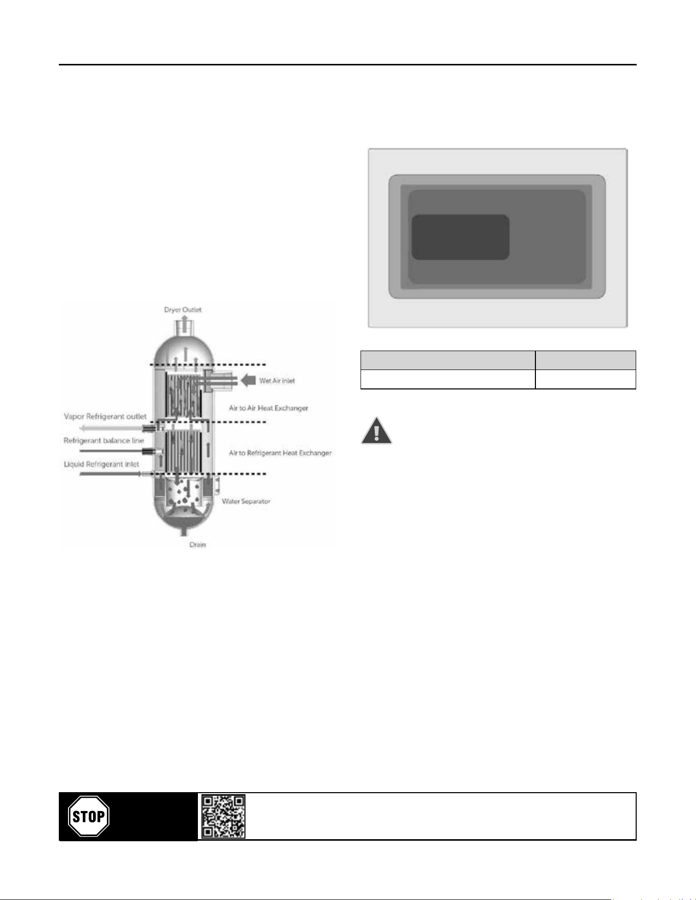
Compressed Air Dryer Working Principle
4) Refrigerant compressor
Increases the pressure of temperature of refrigerant.
There are two types of compressors commonly used
according to refrigerant capacity on this applicaon:
- Piston type
- Scroll type
5) Condenser
Dissipates the heat provided by evaporator and
compressor. there are two types of condensers used
on the applicaon:
- Air Cooled Type (standard)
These condensers are designed to dissipate the heat
to the ambient air. The fans are used to force the air
ow through the cooling ns to enhance the heat
transfer.
- Water Cooled Type (oponal)
These condensers are designed to dissipate the heat
to a water ow. A shell and tube heat exchanger is
used for this purpose.
6) Refrigerant circuit protecon
A) Overload: The single phase refrigerant compressors
are equipped with an overload switch in case of
malfuncon, if overload switches automacally.
B) High Pressure Safety Overload Switch: Refrigerant
line is considered a pressure vessel. That is why it
is protected against bursts by the help of manually
reseng the switch. It is set to 362 psi for dryers
working with R134a refrigerant.
C) Filter dryer: A refrigerant circuit is a close circuit
and total water removal in the refrigerant circuit is
necessary in order to obtain correct operaon.
D) To avoid problems, the refrigerant circuit must be
vacuumed before loading the refrigerant.
E) Water-cooled dryers have a safety high-pressure
switch. In case of cooling water failure, the safety
switch stops the dryer. When the safety switch has
tripped out, it has to be manually reseled before
switching on the dryer.
7) Refrigerant circuit controls
A) Liquid refrigerant injecon: the liquid refrigerant
is released into the evaporator by a control valve.
This is a thermostac valve for maintaining a
constant overheang of the refrigerant in the
evaporator(s).
B) Constant evaporang pressure: In the dryers
equipped with a by-pass valve, the evaporang
pressure is kept constant by a controlled injecon
of hot gas from the high-pressure side into the low-
pressure secon of the circuit.
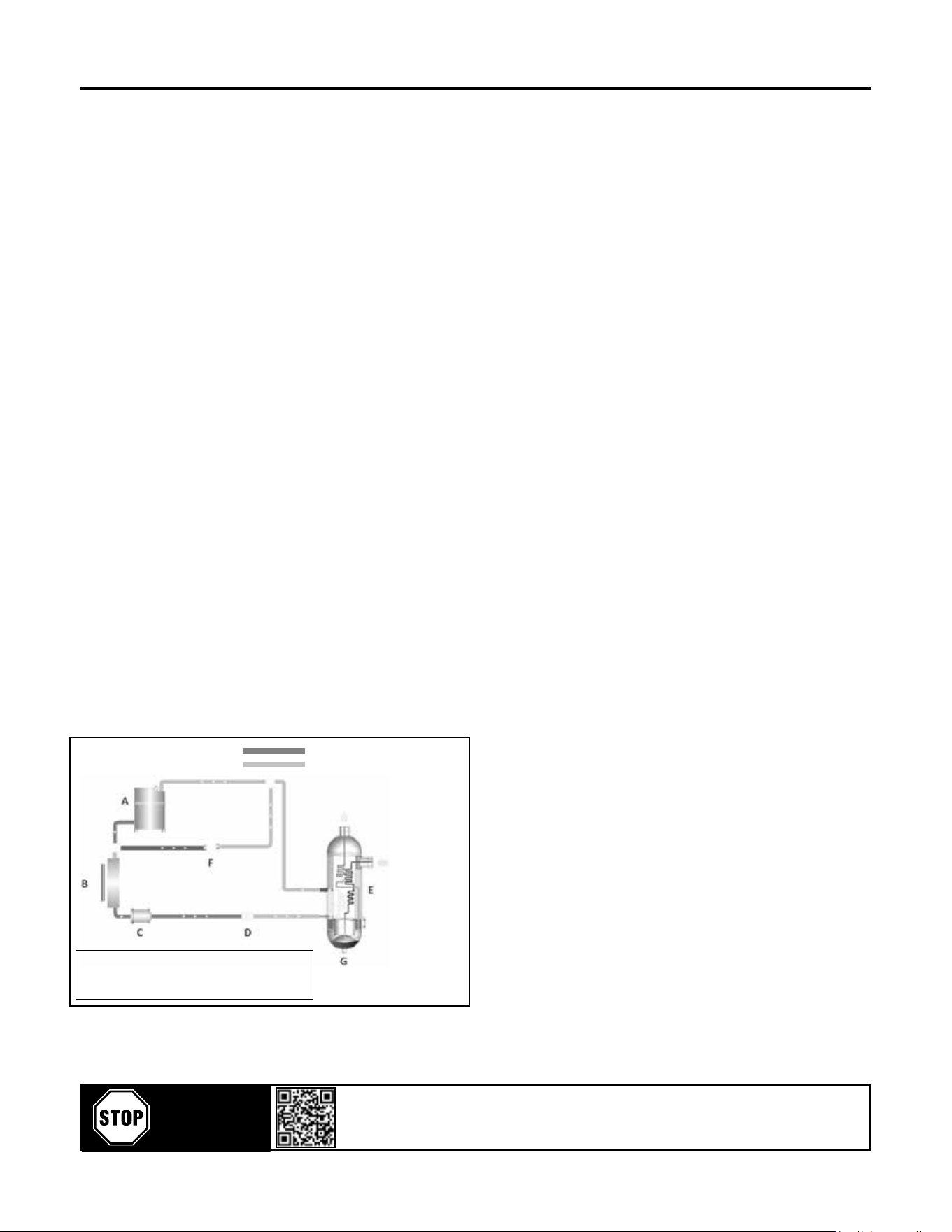
Compressed Dry
Air Outlet
Compressed
Wet Air Inlet
Refrigerant Gas High Pressure Line
Refrigerant Gas Low Pressure Line
A - Refrigerant Compressor
B - Condenser
C - Filter Dryer
D - Expansion Valve
E - Heat Exchanger
F - Hot Gas Bypass Valve
G - Drain
Scan or go to website hosted below:
www.eatoncompressor.com/warranty
Warranty only valid by following conditions expressed in the Warranty Statement section of this Air Dryer Manual.
YOU MUST
REGISTER TO
ACTIVATE
WARRANTY
Flexzilla Pro Energy Ecient Refrigerated Air Dryers
6
8) Condensate drain-trap assembly
Dismantling the drain is easy because it can be
isolated from the air circuit under pressure with a ball
valve. The drain has to be depressurized before being
dismantled.
9) Heat exchanger modular design
A) The dryers are equipped with a compact
This assembly has been specially designed to dry
compressed air and is made of:
1) An economizer which pre-cools the entering hot air
with the out owing cold air.
2) Air/refrigerant exchanger is cooling down the
compressed air.
3) A centrifugal separator concentrang all
condensates and requiring no maintenance.
10) Accessories
Temperature switch: Located inside the dryer, this
temperature switch is adjustable from 32°F up to 95°F.
Digital Controller – DigiPro: This device helps dryer
save energy when there is not any compressed air
ow in the dryer. This informaon can be reached:
Dew point value, periodic maintenance interval
display, status report, run me meter, temperature
unit selecon (°F or °C)
Digital Controller – ESD3: Energy Saving Device: (ESD)
This device helps dryer save energy when there
is not any compressed air ow in the dryer. This
informaon can be reached: Dew point value, periodic
maintenance interval display, status report, run me
meter, temperature unit selecon (°F or °C)
3. OPERATION
Control panels for FDRCF Series
The control panel of the dryer includes the following
elements:
IMPORTANT NOTES
The Dryer has two Compressed Air Filters inside.
It is beer to change lter element for the best
eciency when the alarm status is acve.
It is recommended to keep replacement lter
elements in your stock in order to replace them
when needed.
FDRCF range dryers have low pressure drop
according its competors.
Do not use FDRCF range dryers together with other
dryers which have higher pressure drop without
geng the conrmaon from our technical team.
Single Phase Digital Controller
FDRCF1150030 / FDRCF1150058 Digi-Pro
Scan or go to website hosted below:
www.eatoncompressor.com/warranty
Warranty only valid by following conditions expressed in the Warranty Statement section of this Air Dryer Manual.
YOU MUST
REGISTER TO
ACTIVATE
WARRANTY
Flexzilla Pro Energy Ecient Refrigerated Air Dryers
7
3.1. During Operaon
Regularly check the digital temperature controller
ESD3 or Digi-Pro on dryer.
3.2 Start up and shut-down
Warning: Avoid leaving the dryer o when
compressed air is sll owing through it.
3.3 Starng for the rst me or aer a
long stop
1) Set the rotary switch to “I” This preheats the dryer
and turns the drain system on. It is recommended
to leave the dryer power on permanently so the
crankcase heater runs connuously.
IMPORTANT NOTE
2) Aer a long stop of the dryer it is MANDATORY to
allow a preheang period of minimum 4 hours
before starng again, to avoid any compressed air
ow during preheang.
3) Follow the daily starng and shut down procedure.
3.4 Daily starng and shut-down
A) Push on the ON buon to start the dryer.
B) The start light or Dryer Acve will indicate that
the dryer is running.
C) To stop the dryer, rst stop the airow (either
shut-down the air compressor or close the inlet/
outlet or by-pass valve) When the air ow is
stopped, set the rotary switch on “ 0 “ Set it again
on “ I “ in order to keep the preheang on.
IMPORTANT NOTE
4) Avoid leaving the dryer stopped when compressed
air is sll owing through it.
5) To switch the already preheated dryer on again,
simply push the green start buon.
4) ELECTRICAL CONTROLLER
4.1 DIGI-PRO
4.1.1 Descripon
With the Digi-Pro series controllers, air dryers have
outstanding technology for both funconality and
performance, as well as appearance. The mul-
funconal display provides an accurate digital dew
point display as well as coded alarm monitoring of the
refrigerant dryer.
DIGITAL CONTROLLER ADVANTAGES
• Digital dew point monitoring
• Energy-saving mode display
• Periodic maintenance interval display
• Status report
• Run me meter
• Fahrenheit and Celsius selecon
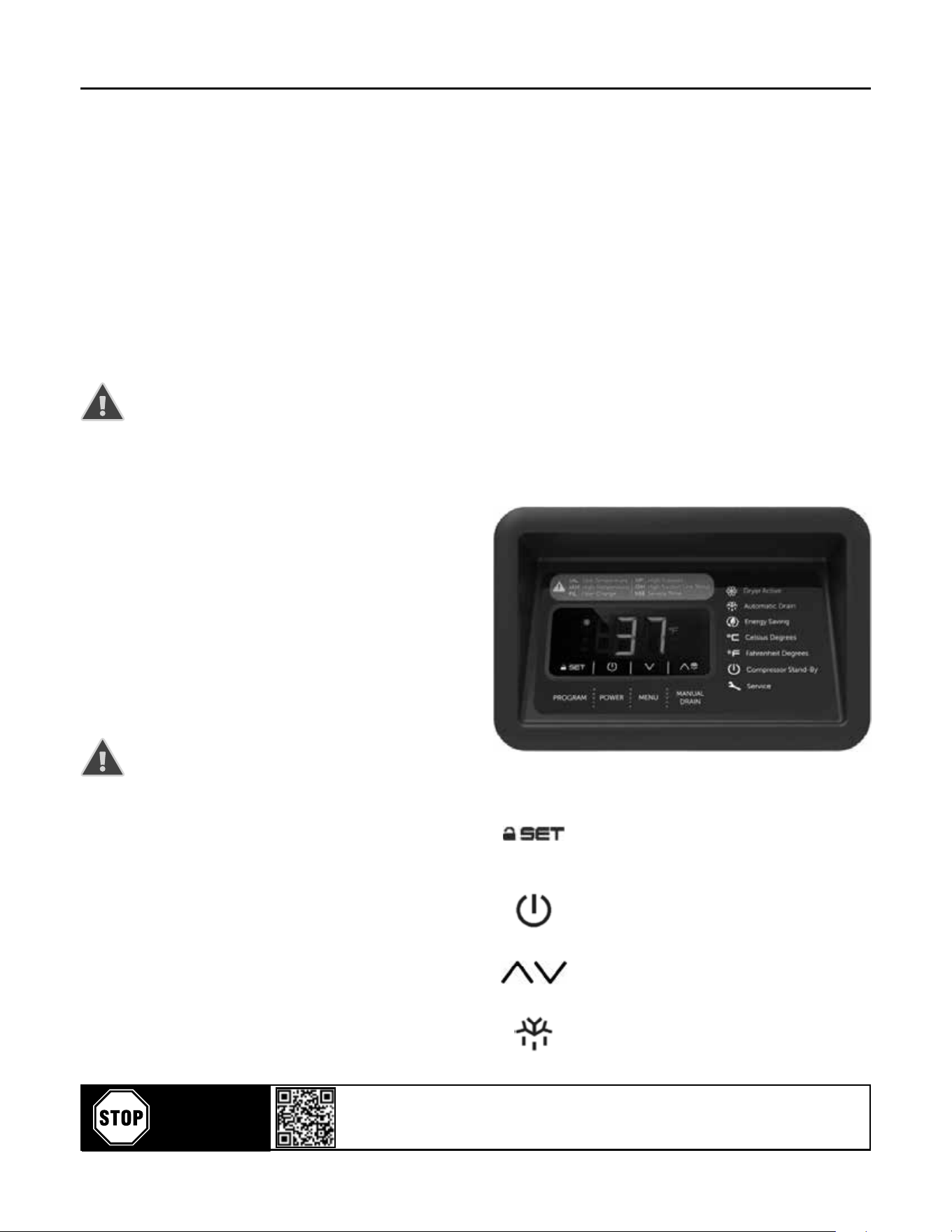
4.1.2 Operaon
Using the Digi Pro controller as shown in the picture
below:
4.1.3 Menu Buons
PROGRAM
To modify the parameter, press
and release buon set. The
menu is used by service tech.
To disable the Key Lock: Press
and hold the SET for 4 seconds.
POWER
This buon is used for starng
and stopping the dryer. Press
and hold for 4 seconds to start
or stop.
MENU
These buons are used to
navigate between screens and
adjust values.
MANUAL DRAIN
This buon is used for manual
control of the drain output.
Press and hold for 4 seconds to
drain manually.
Scan or go to website hosted below:
www.eatoncompressor.com/warranty
Warranty only valid by following conditions expressed in the Warranty Statement section of this Air Dryer Manual.
YOU MUST
REGISTER TO
ACTIVATE
WARRANTY
Flexzilla Pro Energy Ecient Refrigerated Air Dryers
8
4.1.4 ALARM DISPLAY
Alarms / warnings are displayed on the digital
screen. That means the dryer is not working
under normal operang condions, which are outside
the range of set values.
Please contact service when an alarm/warning occurs.
Alarm
Code
Alarm Descripon Reason for Alarm
tAL
Low Temperature Alarm
Refrigerant line temperature is
lower than specied set values.
tAH
High Temperature Alarm
Refrigerant line temperature is
higher than specied set values.
FIL
Filter Change Alarm
Filter element needs to be replaced.
SEr
General Service Alarm
General service me of the dryer.
HP
High Pressure Alarm
Refrigerant high line pressure is
higher than specied set values.
Pr1
Temperature Probe Alarm
Temperature sensor is faulty.
tSH
High Sucon Line Temp
Temperature of refrigerant sucon
line is higher than specied set
values.
4.1.5 MODE DISPLAY
DRYER ACTIVE MODE
This mark indicates that the
dryer is performed in acve
state and drying.
AUTOMATIC DRAIN MODE
Shows if the drain system is
acvated.
ENERGY SAVING MODE
Shows if the energy saving
mode is acvated.
CELSIUS UNIT MODE
Indicates that Celsius
temperature unit is selected.
FAHRENHEIT UNIT MODE
Indicates that Fahrenheit
temperature unit is selected.
COMPRESSOR STANDBY MODE
This mode shows that the dryer
is ready for drying operaon.
SERVICE MODE
This mode shows that the dryer
in the service me.
4.2 ESD 3
4.2.1 DESCRIPTION
E-687 is designed as a controller for refrigerant
type compressed air dryers. The controller has 8
temperature sensor inputs.
The controller has an RS-485 communicaon interface
that can be used for remotely monitoring channel
temperatures, set points, input and output status.
Modbus RTU protocol is used for communicaon.
The front panel of the controller contains a four line
20 character LCD display and buons that are used in
conguraon and manual control operaons.
The dimensions of the controller are 3.7 x 7.5 in.
(front panel) with a depth of 4.3 in..
The panel cutout should be 3.5 x 7.2 in..
The operang voltage of the controller is 20 - 60V AC
or 20 - 85V DC.
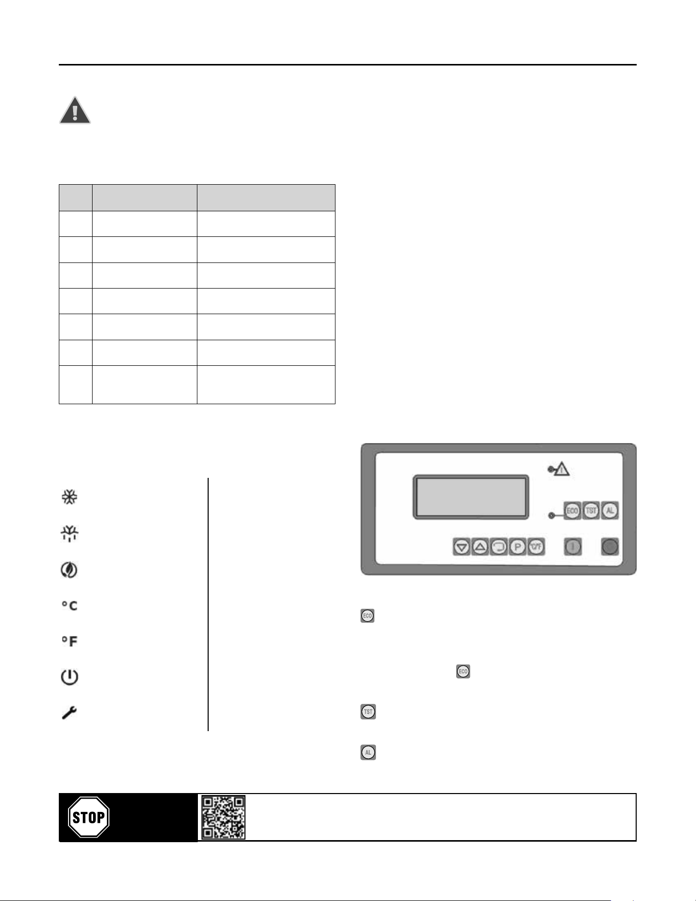
4.2.2 OPERATION
The front panel view of E-687 controller is shows in
the below gure. The front panel of the controller
contains a four line 20 character LCD display, 10
buons and 2 indicator LEDs.
The Front Panel View of E-687 Controller
buon is used to enable or disable the ECO
(economy) mode. Pressing this buon complements
the state of ECO, i.e. if it is enabled; disables, if it is
disabled; enables the ECO mode. The green LED on
the le side of the buon lights if the ECO mode is
enabled.
buon is used for manual control of the drain
output.
buon is used for alarm acknowledge. The dryer
is automacally stopped if an fault is detected. In that
Scan or go to website hosted below:
www.eatoncompressor.com/warranty
Warranty only valid by following conditions expressed in the Warranty Statement section of this Air Dryer Manual.
YOU MUST
REGISTER TO
ACTIVATE
WARRANTY
Flexzilla Pro Energy Ecient Refrigerated Air Dryers
9
case, the alarm output and the alarm indicator LED
(red) on the front panel become acvated. In order to
restart the dryer, alarm should be acknowledged and
“restart delay” period should be med out. Pressing
buon acknowledges the alarm and reenergizes the
alarm output and alarm LED.
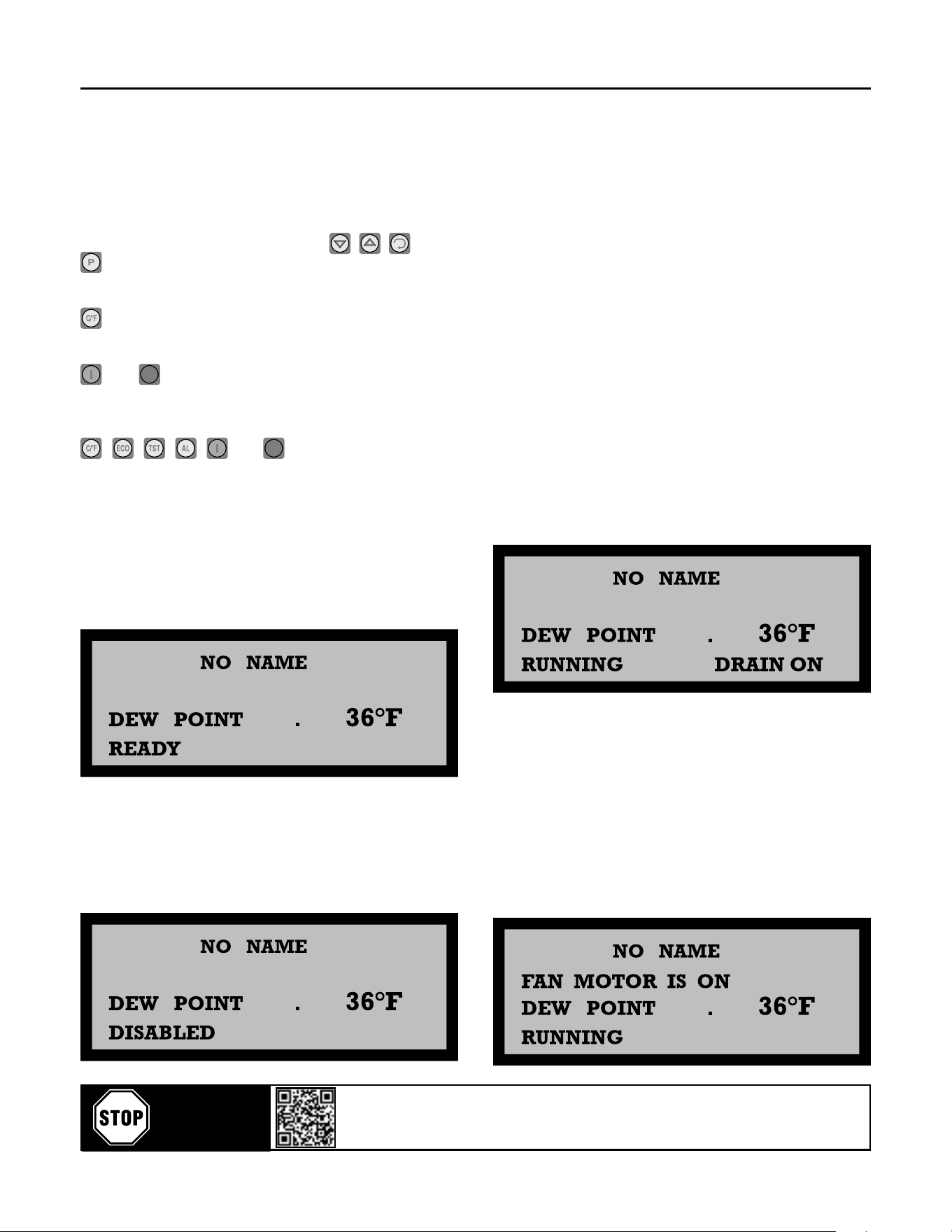
The buons below the LCD display ( , , and
) are used in screen selecon and conguraon
operaons.
buon is used to change the temperature unit
from °C to °F or vice versa.
and buons are used for starng and stopping
the dryer. If the dryer is stopped manually, it cannot
be started before “restart delay” period is med out.
, , , , and buons are disabled
during conguraon operaons.
4.2.3 OPERATION SCREENS
4.2.3.1 The Normal Operaon Screen
When the controller is powered on, it displays the
type and a message, and then the restart delay mer
is set to 5 seconds. Aer 5 seconds, the normal
operaon screen is displayed as shown in below gure:
The exchanger temperature (Dew Point) and
operaon state of the dryer is displayed in this screen.
If there is a situaon which will prevent the operaon
of the dryer then the “READY” message in the last line
will become “DISABLED”. See below gure:
In order to start the dryer, the following condions
must be sased.
1. All the temperatures except the exchanger
temperature and condenser outlet temperature must
be between their low and high limits. The low pressure
line temperature can be ‘HIGH’.
2. Digital Input 3 (Compressor Fault) is not acvated.
3. Digital Input 4 (Compressor Overload) is not acvated.
4. Digital Input 5 (Fan Fault) is not acvated.
5. Digital Input 6 (Fan Overload) is not acvated.
6. Digital Input 7 (Phase Sequence Error) is not acvated.
7. Digital Input 8 (Remote Disable) is not acvated.
8. Digital Input 11 (High Pressure) is not acvated.
9. Digital Input 12 (Low Pressure) is not acvated.
If all the above condions are checked, the message
in the last line of the normal operaon screen will be
“READY” and the dryer can be started either pressing
buon on the front panel or acvang Digital Input 1
(Remote Start) or acvang Digital Input 13 (Remote
Control). When the dryer is started, the normal
operaon screen is displayed as shown in below gure:
In the beginning, Digital Output 1 (Compressor Motor),
Digital Output 2 (Drain Output) and Digital Output 3
(Dryer is Running) become acve. While in normal
operaon, the drain output is controlled according to the
congured “drain on” and “drain o” periods. “DRAIN
ON” message is displayed in the end of the last line while
the drain output is acve.
When the Digital Input 9 (Fan Motor is on) is acvated,
“FAN MOTOR IS ON” message is displayed in the second
line as shown in below gure:
Scan or go to website hosted below:
www.eatoncompressor.com/warranty
Warranty only valid by following conditions expressed in the Warranty Statement section of this Air Dryer Manual.
YOU MUST
REGISTER TO
ACTIVATE
WARRANTY
Flexzilla Pro Energy Ecient Refrigerated Air Dryers
10
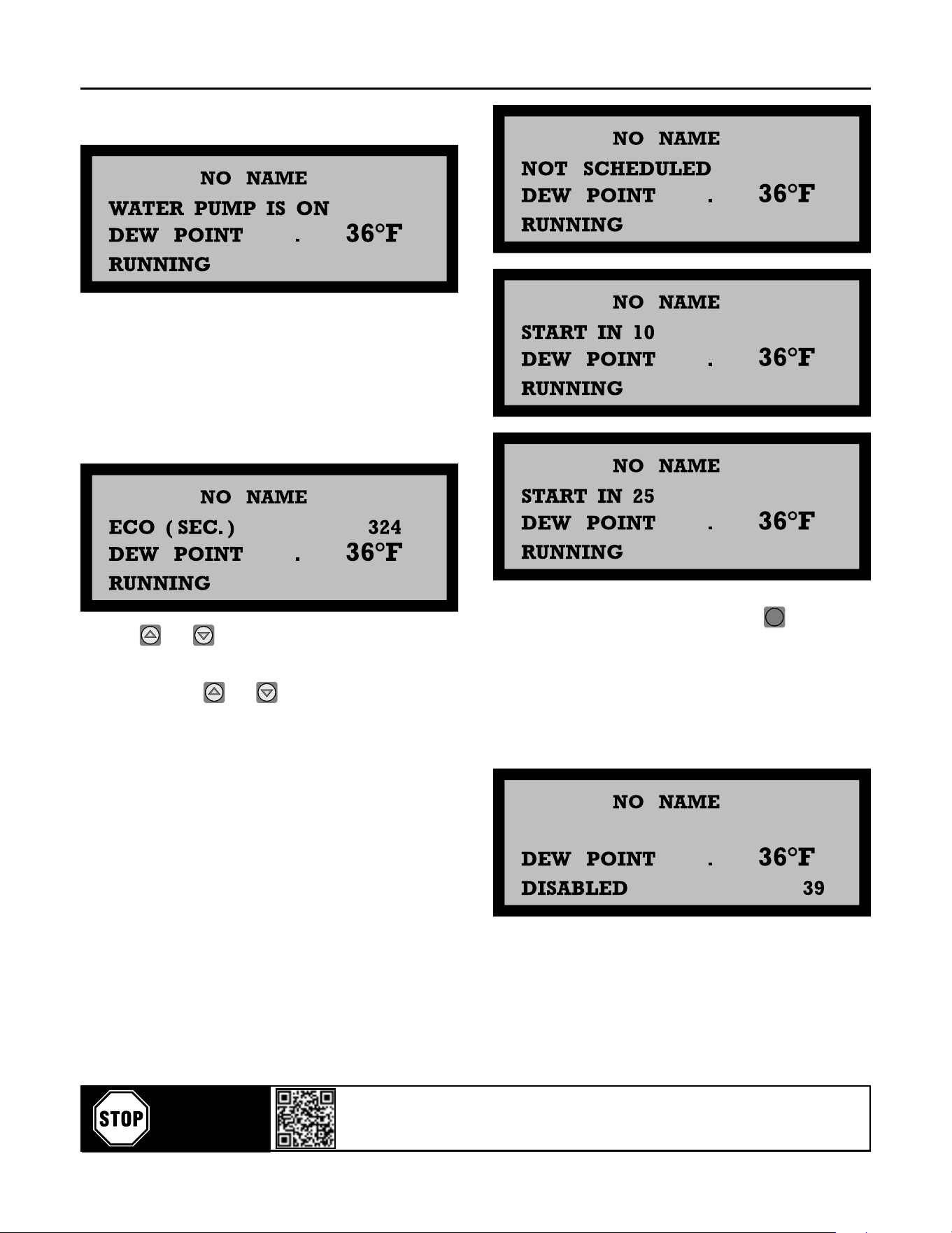
Digital Input 14 (Water Pump is on) acvates “WATER
PUMP IS ON” message as shown in below gure:
When ECO mode is enabled and the exchanger
temperature is less than or equal to “ECO Start Set
point” and this condion is prevailed more than “ECO
Start Delay”, then, the compressor motor is stopped
and ECO operaon starts. During the ECO operaon the
appearance of the display is given in below gure. The
value at the end of the second row indicates the me in
seconds since beginning of the ECO operaon.
Pressing and keys simultaneously at this page
toggles the controller between automac and manual
mode. In manual mode, the dryer starts and stops
manually by using and buons. Unlike the
manual mode, automac mode enables the controller to
start and stop automacally at pre-programmed mes
on a daily basis.
When running in automac mode, current scheduling
informaon messages are also acvated in the second
line of the displays as show in below gure. “NOT
SCHEDULED” message is displayed when no schedule
exists. “START IN XXX” shows the me to the next
scheduled program in minutes and “STOP IN XXX”
message shows the me to the end of current running
program in minutes.
If the dryer is stopped manually by using buon, or
acvang Digital Input 2 (Remote Stop) or deacvang
Digital Input 13 (Remote Control), the normal operang
screen is displayed as shown in below gure. The
number at the end of the last line indicates the
remaining me in seconds from the restart delay. If this
number becomes zero and there is no anomaly, the
dryer can be restarted.
The rst line in the normal operaon screen (NO NAME)
is user congurable.
If the exchanger temperature sensor is broken, dew
point temperature will be displayed as 1000ºC.
Scan or go to website hosted below:
www.eatoncompressor.com/warranty
Warranty only valid by following conditions expressed in the Warranty Statement section of this Air Dryer Manual.
YOU MUST
REGISTER TO
ACTIVATE
WARRANTY
Flexzilla Pro Energy Ecient Refrigerated Air Dryers
11
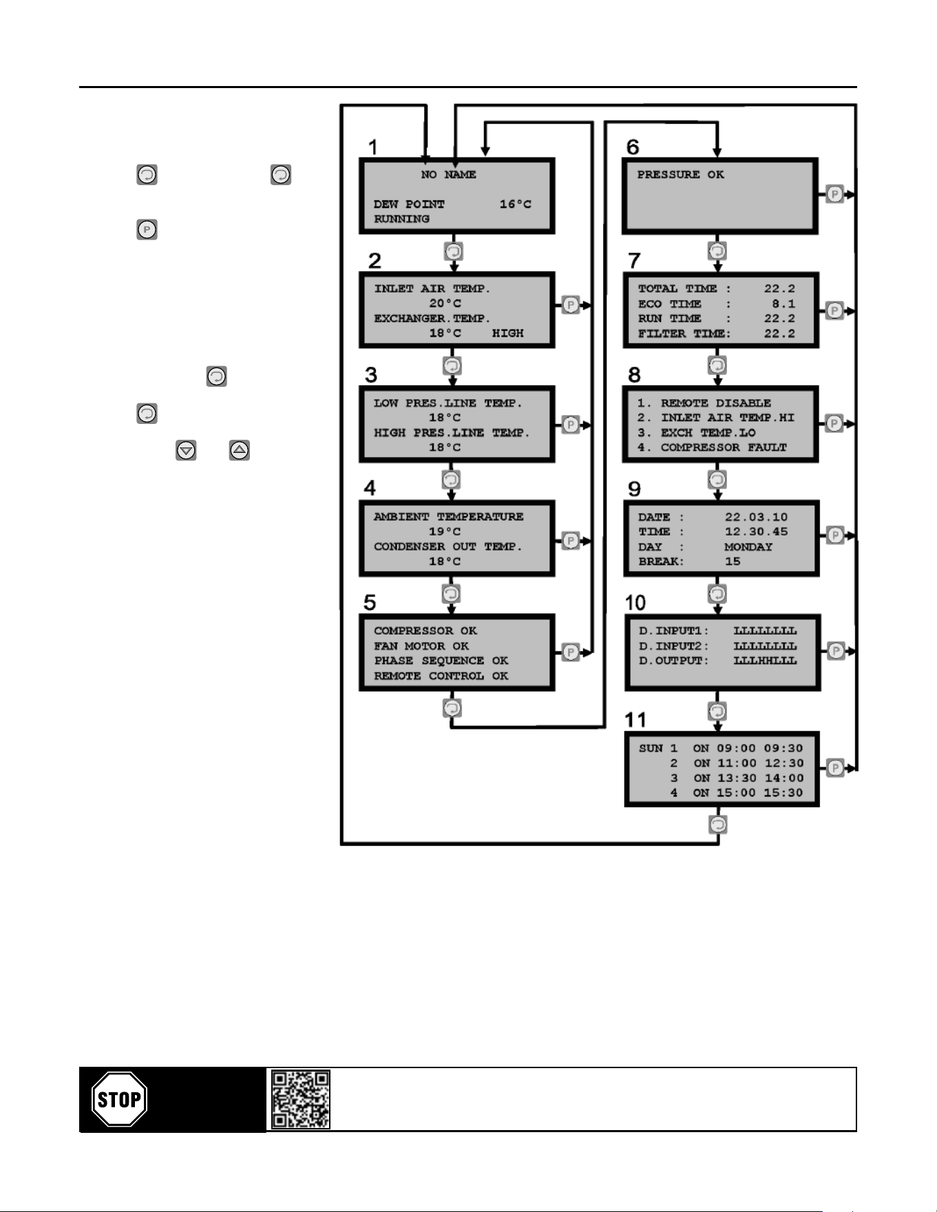
4.2.4 The Info Screens
Various data related to the dryer
can be monitored by sequenally
pressing buon. Pressing
buon, changes the display screen.
While one screen is displayed,
pressing buon reverts to the
normal operaon screen. The ow
chart for monitoring the dryer data
is given in gure on right. In this
gure, screen numbers are shown
on the upper le of the screens.
Screen 1 is the normal operaon
screen. While this screen is
displayed, pressing buon
selects Screen 2. By successively
pressing buon, all the screens
can be accessed. Screens can also
be selected by and buons.
In Screen 2, Screen 3 and Screen
4, the sensor temperatures
are displayed. If the measured
temperatures are between their
low and high limits, only the
temperature value is displayed,
otherwise “LOW” or “HIGH”
message is added in the end of
the line. In case of sensor break,
only “SENSOR BREAK” message
is displayed.
In Screen 5 and 6 the states
of the compressor motor, fan
motor, the phase sequence,
remote disable and air pressure
are displayed. This data is
derived from the digital inputs.
The message in the rst line
of Screen 5 is determined
by Digital Input 3 and Digital
Input 4 (Compressor Fault and
Compressor Overload). The
gure on right shows the relaon
between digital inputs and the
message.
Scan or go to website hosted below:
www.eatoncompressor.com/warranty
Warranty only valid by following conditions expressed in the Warranty Statement section of this Air Dryer Manual.
YOU MUST
REGISTER TO
ACTIVATE
WARRANTY
Flexzilla Pro Energy Ecient Refrigerated Air Dryers
12
Screen 8 displays the last four events that caused the
dryer stopping automacally. The possible alternaves
for these messages are given below.
INLET AIR TEMP.LO
INLET AIR TEMP.HI
EXCH.TEMP.LO
EXCH.TEMP.HI
LO.PRES.L.TEMP.LO
LO.PRES.L.TEMP.HI
HI.PRES.L.TEMP.LO
HI.PRES.L.TEMP.HI
AMB.TEMP.LO
AMB.TEMP.HI
COMPRESSOR FAULT
COMP.OVERLOAD FAN
MOTOR FAULT FAN
MOT.OVERLOAD PHASE
SEQ.ERROR REMOTE
DISABLE PRESSURE
HIGH PRESSURE LOW
CONDENSER FAULT
Screen 9 displays the date and me.
Screen 10 displays the states of the digital inputs and
digital outputs. The leers ‘L’ and ‘H’ stands for ‘not
acvated’ and ‘acvated’ states respecvely.
The data in the rst line of Screen 10 (D.INPUT1), from
right to le corresponds to Digital Input 1 to 8.
The data in the second line of Screen 10 (D.INPUT2),
from right to le corresponds to Digital Input 9 to 16.
The data in the third line of Screen 10 (D.OUTPUT),
from right to le corresponds to Digital Output 1 to 8.
Screen 11 displays automac mode scheduling for the
day. Please see Secon 2.3.3 for scheduling for auto/
manual selecon.
4.3.4 Operaon Principles
In order to start the dryer, the following condions
must be sased.
1. All the temperatures except the exchanger
temperature and condenser outlet temperature
must be between their low and high limits. The low
pressure line temperature can be ‘HIGH’.
2. Digital Input 3 (Compressor Fault) is not acvated.
3. Digital Input 4 (Compressor Overload) is not
acvated.
4. Digital Input 5 (Fan Fault) is not acvated.
5. Digital Input 6 (Fan Overload) is not acvated.
6. Digital Input 7 (Phase Sequence Error) is not
acvated.
7. Digital Input 8 (Remote Disable) is not acvated.
8. Digital Input 11 (High Pressure) is not acvated.
9. Digital Input 12 (Low Pressure) is not acvated.
If all the above condions are sased, the dryer
can be started.
5. TECHNICAL SPECIFICATIONS
Model FDRCF1150030 FDRCF1150058
Capacity (scfm) 29 50
Pressure drop (psig) 2,8 1,6
Connecon Size 1/2” NPT 3/4” NPT
Amount of Refrigerant
(pounds)
0.7 1.2
Refrigerant gas R134a R134a
Noise Level (dB) <70 <70
FOR ALL MODELS
Nominal Working Pressure 100 psig
Maximum Working Pressure 230 psig
Maximum Ambient Tempature 122°F
Minimum Ambient Temperature 39°F
Maximum Inlet Temperature 140°F
6. DIAGRAMS
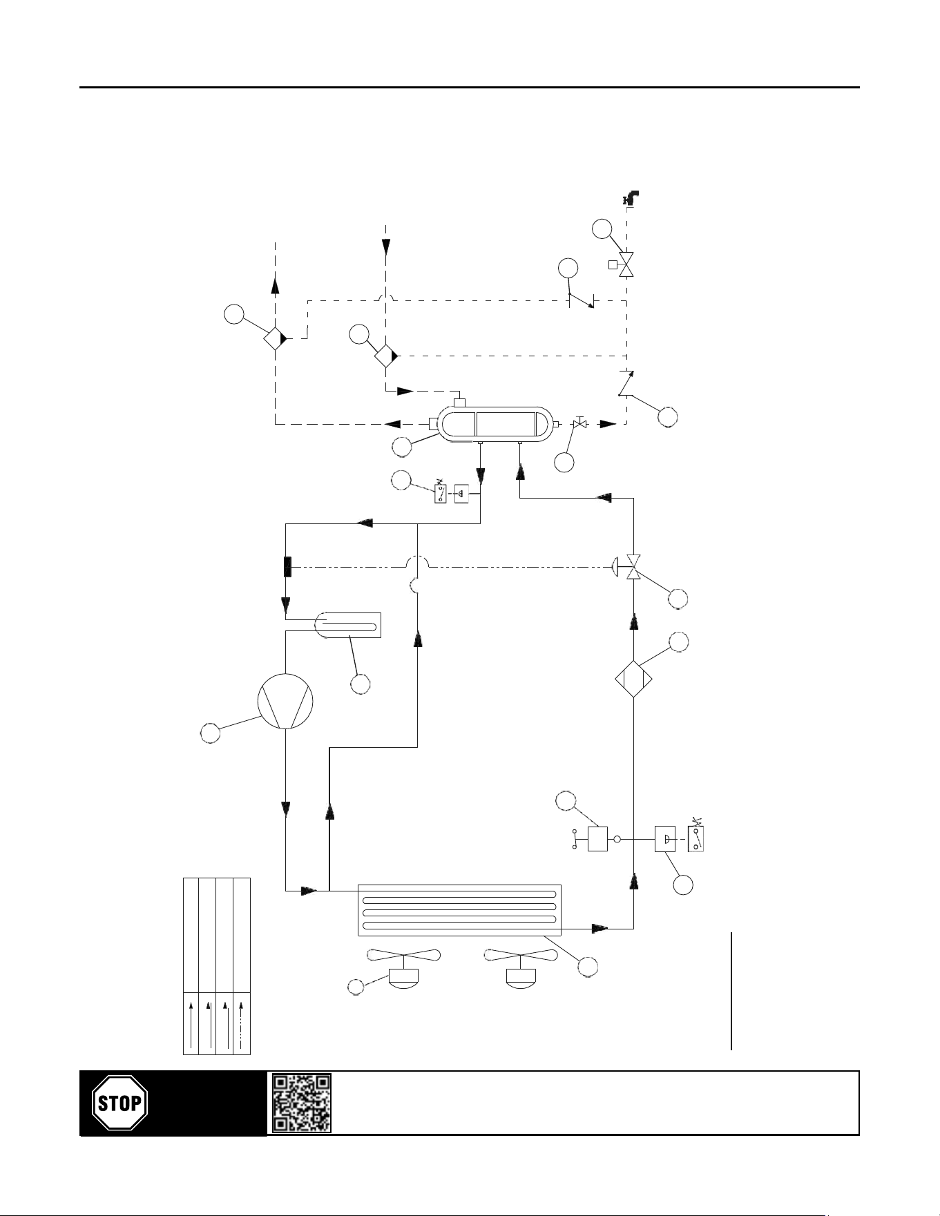
6.1 AIR FLOW DIAGRAMS
FDRCF1150030 / FDRCF1150058
POS. DESCRIPTION QTY
1 COMPRESSOR
2 FAN MOTOR
3 CONDENSER
4 FAN SWITCH
5 HIGH PRESSURE SWITCH
6 LIQUID RECEIVER
7 FILTER DRYER
8 EXPANSION VALVE
9 BY-PASS VALVE
10 LIQUID SEPARATOR
11 LOW PRESSURE SWITCH
12 HEAT EXCHANGER
13 FILTER
14 MANUAL VALVE
15 SOLENOID VALVE
16 CHECK VALVE
Scan or go to website hosted below:
www.eatoncompressor.com/warranty
Warranty only valid by following conditions expressed in the Warranty Statement section of this Air Dryer Manual.
YOU MUST
REGISTER TO
ACTIVATE
WARRANTY
Flexzilla Pro Energy Ecient Refrigerated Air Dryers
13
6.1 AIR FLOW DIAGRAMS
FDRCF1150030 / FDRCF1150058
1
11
AIR OUTLET
2
11
8
AIR INLET
9
10
4
12
14
3
13
S
Drain
Outlet
14
6
7
5
IMPORTANT NOTICE:
-
High Pressure Switch (Part No:5) is not used on FDRCF1150030.
S
M
M
S
REFRIGERANT GAS FLOW LINE
COMPRESSED AIR FLOW LINE
DRAIN FLOW LINE
PILOT FLOW LINE
Scan or go to website hosted below:
www.eatoncompressor.com/warranty
Warranty only valid by following conditions expressed in the Warranty Statement section of this Air Dryer Manual.
YOU MUST
REGISTER TO
ACTIVATE
WARRANTY
Flexzilla Pro Energy Ecient Refrigerated Air Dryers
14
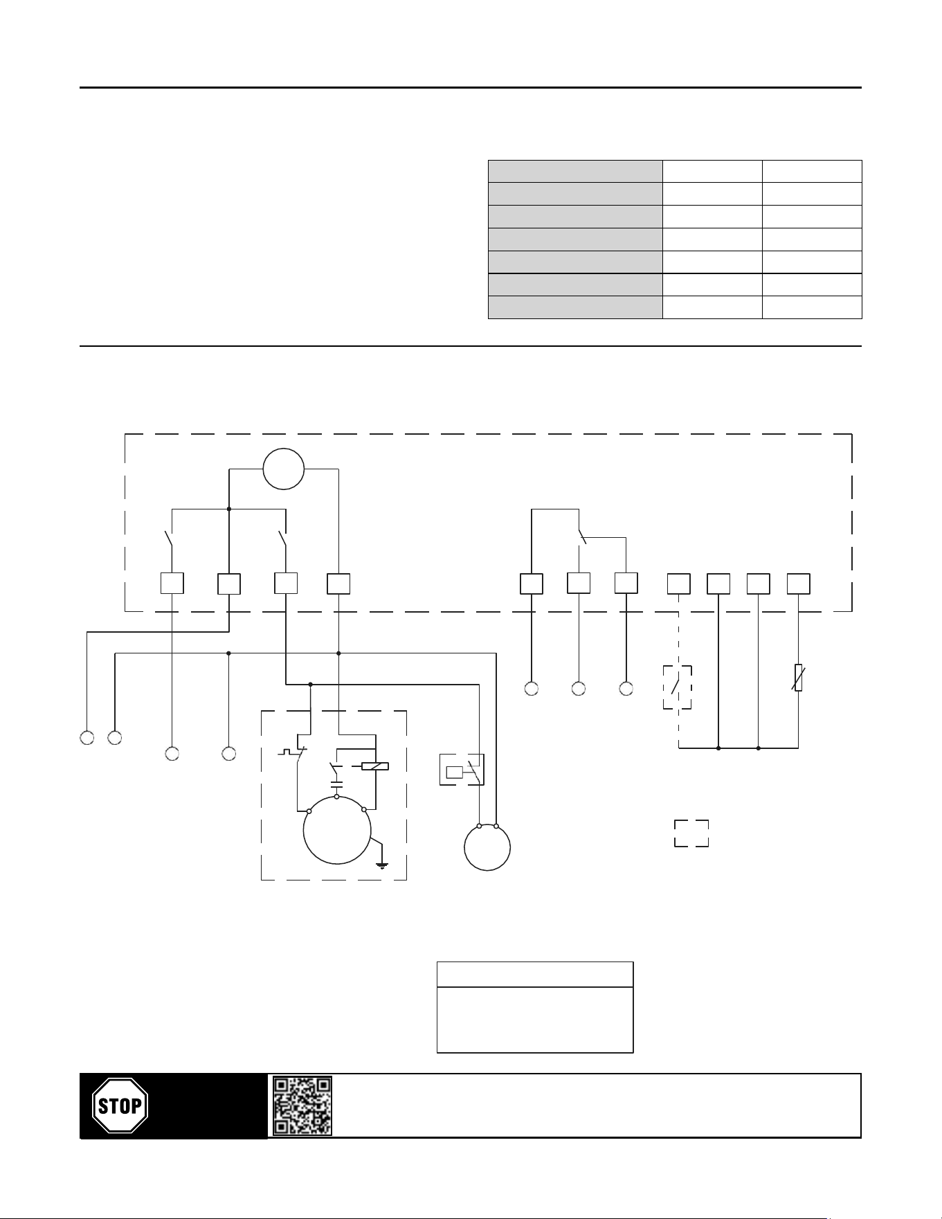
6.2 ELECTRICAL DIAGRAMS
With Control & Power
“User must supply the protecve earth conductor of
the dryer. The conductor is to be connected to the
point on the conducng body of the dryer, specied
by a scker with the protecve earth symbol next
to it. The size of the protecve earth conductor
should be minimum the size of the power conductor,
minimum 16 mm² for power conductor size between
16 and 35 mm², minimum half the size of the
conductor if it is larger than 35 mm²."
Model FDRCF1150030 FDRCF1150058
Voltage/Phase/Hertz 115/1P/60 115/1P/60
INSTALLED POWER (kWa) 0.42 0.69
Nominal Current (Amp) 3.92 7.42
MCA (A) 5.11 9.20
TOTAL LRA (A) 22.48 33.70
Fuse (Amp) 6 10
~
EV3
SP
EV3: Controller
SP: Power supply
AL: Alarm contacts
A20: Drain supply
DR: Drain valve relay
A40-1: Start capacitor
K01: Compressor start relay
K02: Compressor motor contactor
K30: Alarm relay
S10: Fan pressure switch
S16: Filter service contact (optional)
M01: Compressor motor
M10: Fan motor
P: Compressor motor overload protector
PT: Temperature sensor (NTC)
HP indicates high pressure.
DR
K01
K30
1
3
10
11
12
2
4
5
2
3
4
12
4
4
PT
1
4
5
6
7
S16
AL
4
3
19
L
4
N
P
S10
1
4
10
A
20
P
K01
A40-1
MAXIMUM SET: %15
A/S
C/C P/R
M
l
~
FIELD INSTALLED
M
l~
M10
ELECTRICAL
SPECIFICATIONS
FAN MOTOR
UN 115V/1~/60Hz
M01
S01 MAIN PROTECTION AND DISCONNECTING MEANS
SHALL BE PROVIDED BY THE INSTALLER OF
RESIDUAL CURRENT AUTOMATIC CIRCUIT BREAKER
SUPPLY LINE VOLTAGE RATING - 600 VAC
COMPRESSOR
UN 115V/1~/60Hz
FDRCF1150030 RLA 3,7A 0,285kW
FDRCF1150030 RLA 0,35A 0,055kW
ELECTRICAL SUPPLY LINE
SINGLE PHASE + PROTECTION EARTH
CABLES SIZE
FDRCF1150030 3AWG14
9
6
7
H
6.2 ELECTRICAL DIAGRAMS
FDRCF1150030
Scan or go to website hosted below:
www.eatoncompressor.com/warranty
Warranty only valid by following conditions expressed in the Warranty Statement section of this Air Dryer Manual.
YOU MUST
REGISTER TO
ACTIVATE
WARRANTY
Flexzilla Pro Energy Ecient Refrigerated Air Dryers
15
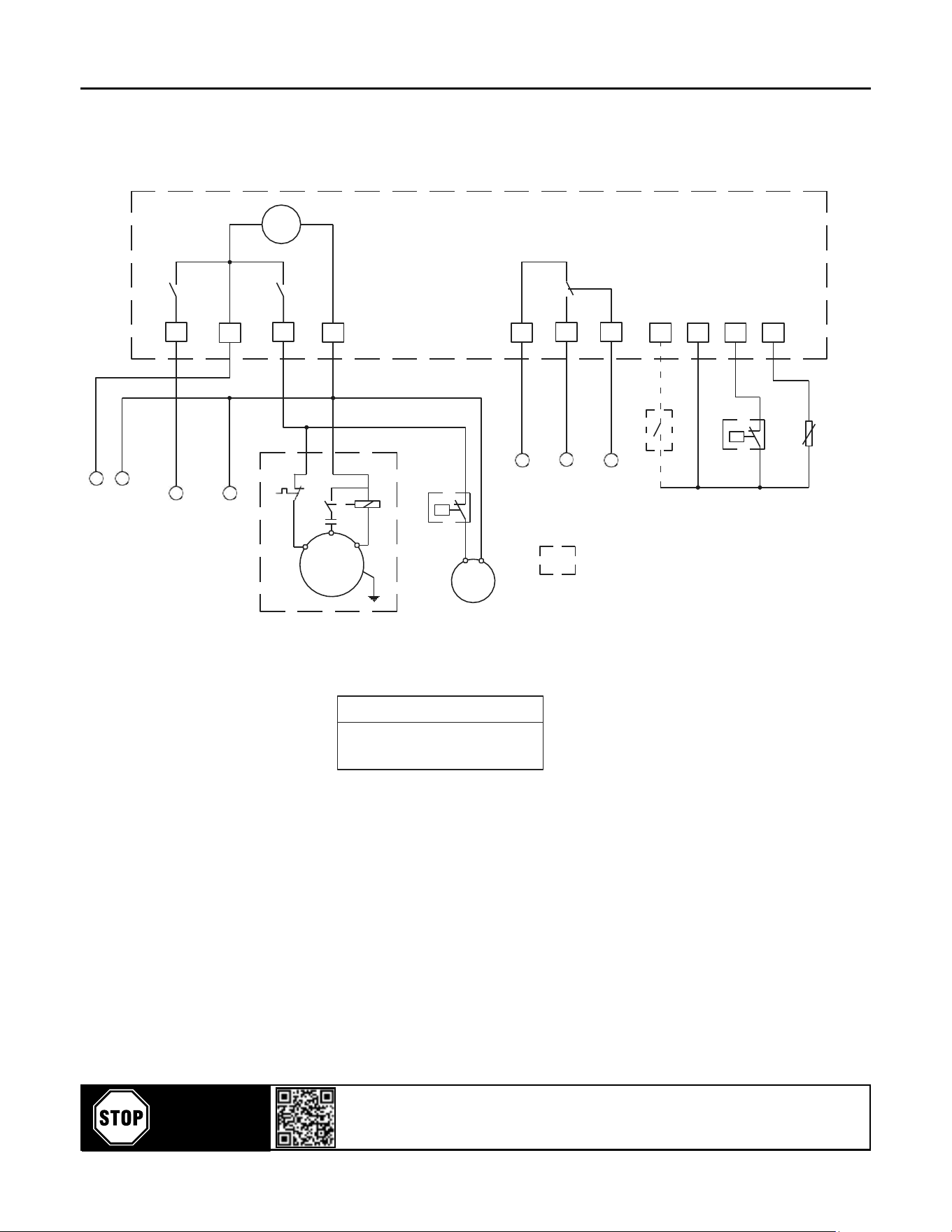
6.2 ELECTRICAL DIAGRAMS
FDRCF1150058
~
SP
EV3
EV3: Controller
SP: Power supply
AL: Alarm contacts
A20: Drain supply
DR: Drain valve relay
A40-1:Start capacitor
K01: Compressor start relay
K02: Compressor motor contactor
K30: Alarm relay
S10: Fan pressure switch
S11: High pressure switch
S16: Filter service contact (optional)
M01: Compressor motor
M10: Fan motor
P: Compressor motor overload protector
PT: Temperature sensor (NTC)
HP indicates high pressure
DR
K01
K30
1
2
3
4
5
10
11
12
2
3
4
12
11
4
4
S11
10
1
4
S16
PT
P
4
3
6
5
7
10
19
L
4
N
AL
P
S10
1
4
10
A20
P
K01
A40-1
A/S
C/C P/R
MAXIMUM SET: %15
M
l
~
M
l~
M10
FIELD INSTALLE
D
M01
ELECTRICAL
SPECIFICATIONS
COMPRESSOR
UN 115V/1~/60Hz
FDRCF1150058 RLA 6A 0,466kW
FAN MOTOR
UN 115V/1~/60Hz
FDRCF1150058 RLA 0,95A 0,110kW
S01 MAIN PROTECTION AND DISCONNECTING MEANS
SHALL BE PROVIDED BY THE INSTALLER OF
RESIDUAL CURRENT AUTOMATIC CIRCUIT BREAKER
SUPPLY LINE VOLTAGE RATING - 600 VAC
ELECTRICAL SUPPLY LINE
SINGLE PHASE + PROTECTION EARTH
CABLES SIZE
FDRCF1150058 3AWG14
H
9
6
7
H
Scan or go to website hosted below:
www.eatoncompressor.com/warranty
Warranty only valid by following conditions expressed in the Warranty Statement section of this Air Dryer Manual.
YOU MUST
REGISTER TO
ACTIVATE
WARRANTY
Flexzilla Pro Energy Ecient Refrigerated Air Dryers
16
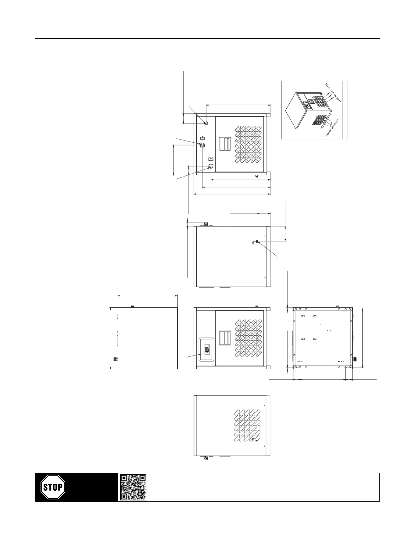
7. ID DIAGRAM DRAWINGS &
GENERAL ARRANGEMENTS
7.1 ID DIAGRAM DRAWINGS
FDRCF1150030 / FDRCF1150058
17,795" (452mm)
`
0,078"
8,72" (221,5mm)
`
0,078"
AIR INLET
1/2" NPT
2,559" (65mm)
`
0,078"
AIR
OUTLET
1/2" NPT
2,834" (72,0mm)
`
0,078"
TOP VIEW
1,155" (29,35mm)
`
0,078"
DIGITAL CONTROLLER
CABLE
CONNECTION
FRONT VIEW
LEFT VIEW
BACK VIEW
DRAIN
0,492"
`
0,039"
1/4"
NPT
(12,5mm)
RIGHT VIEW
4,33"
`
0,039"
(110mm)
0,492"
`
0,039"
(12,5mm)
ISOMETRIC VIEW
427,00
`
1,0
BOTTOM VIEW
1,982"
`
0,039"
(50,35mm)
13,357"
`
0,039"
(339,29mm)
1,982"
`
0,039"
(50,35mm)
17,48" (444mm)
`
0,078"
3,937"
`
0,039"
(100mm)
22,303" (566,5mm)
`
0,078"
19,783" (502,5mm)
`
0,078"
17,322"
(440mm
)
`
0,078"
18,71" (475,25mm)
`
0,078"
Scan or go to website hosted below:
www.eatoncompressor.com/warranty
Warranty only valid by following conditions expressed in the Warranty Statement section of this Air Dryer Manual.
YOU MUST
REGISTER TO
ACTIVATE
WARRANTY
Flexzilla Pro Energy Ecient Refrigerated Air Dryers
17
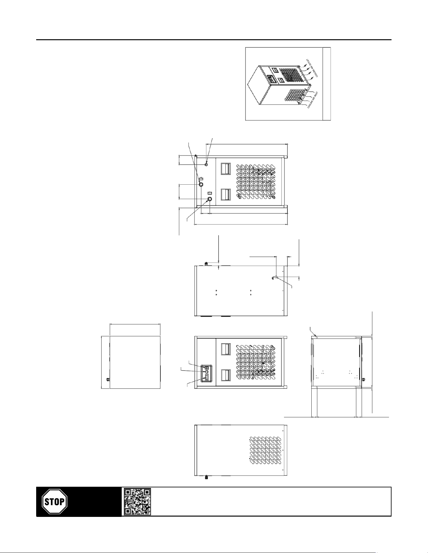
7.2 ID DIAGRAM DRAWINGS
FDRCF1150030 / FDRCF1150058
18,62"(473mm)
TOP VIEW
3,17"(80,5mm)
5,10"(129,6mm)
3,23"(82mm)
FILTER CHANGE BUZZER
ON-OFF BUTTON
DEWPOINT
INDICATOR
AIR INLET
3/4" NPT
AIR OUTLET
3/4" NPT
CABLE CONNECTION
1,15"(29,3mm)
DRAIN
3,94"(100mm)
LEFT VIEW
FRONT VIEW
BACK VIEW
RIGHT VIEW
M8x4
ISOMETRIC VIEW
0,51"(13mm)
17,60"(447mm)
0,51"(13mm)
BOTTOM VIEW
2,03"(51,5m
m)
13,78"(350m
m)
2,03"(51,5m
m)
17,83"(453mm)
3,94"(100mm)
32,75"(831,8mm)
27,33"(694,1mm)
3,05"(77,5mm)
28,54"(725mm)
Scan or go to website hosted below:
www.eatoncompressor.com/warranty
Warranty only valid by following conditions expressed in the Warranty Statement section of this Air Dryer Manual.
YOU MUST
REGISTER TO
ACTIVATE
WARRANTY
Flexzilla Pro Energy Ecient Refrigerated Air Dryers
18
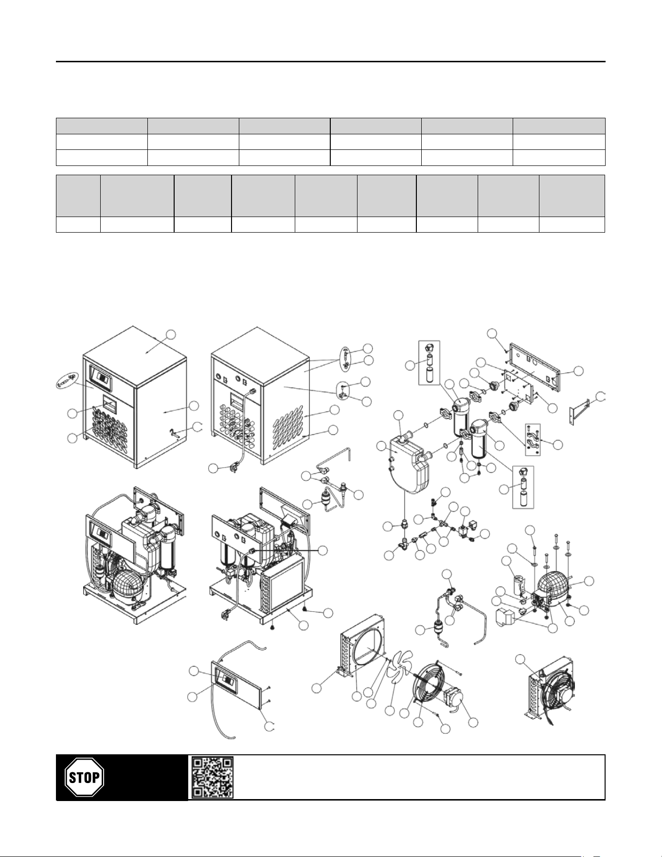
7.3 GENERAL ARRANGEMENTS
FDRCF1150030 / FDRCF1150058
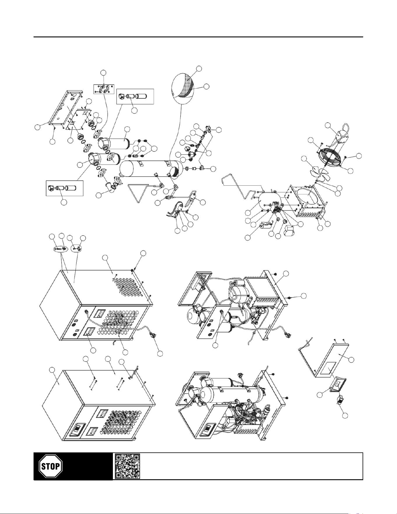
8. FDRCF EXPLODED DIAGRAMS & SPARE PARTS LISTS
8.1 - ED & Spare Part List
FDRCF1150030
Model Element Type Length (inch) Width (inch) Height (inch) Weight (lbs)
FDRCF1150030 FILTERKIT011 17.48 17.79 22.30 72.00
FDRCF1150058 FILTERKIT012 17.83 18.62 32.76 116.60
ALL
MODELS
Superheat of
thermostac
expansion valve
Evaporang
pressure
Fan pressure
switch
Security high
pressure
switch
Security low
pressure
switch
Drain Timer
Refrigerant
temperature
switch
Water ow
valve (if water
condenser)
41.0°F - 50.0°F 29.7 psi 130.5 - 174 psi 162.5 psi 23.2 psi 5 min. - 5 sec. 113°F 159.5 psi
50
58
49
59
40
32
38
39
61
33
29
34
60
55
42
54
56
10
36
61
57
31
28
11
35
15
18
35
62
63
37
41
44
45
16
19
30
12
6
18
17
15
26
25
52
13
14
44
43
24
23
27
53
63
21
1
22
45
46
48
50
8
9
2
47
3
7
4
5
51
6
Scan or go to website hosted below:
www.eatoncompressor.com/warranty
Warranty only valid by following conditions expressed in the Warranty Statement section of this Air Dryer Manual.
YOU MUST
REGISTER TO
ACTIVATE
WARRANTY
Flexzilla Pro Energy Ecient Refrigerated Air Dryers
19
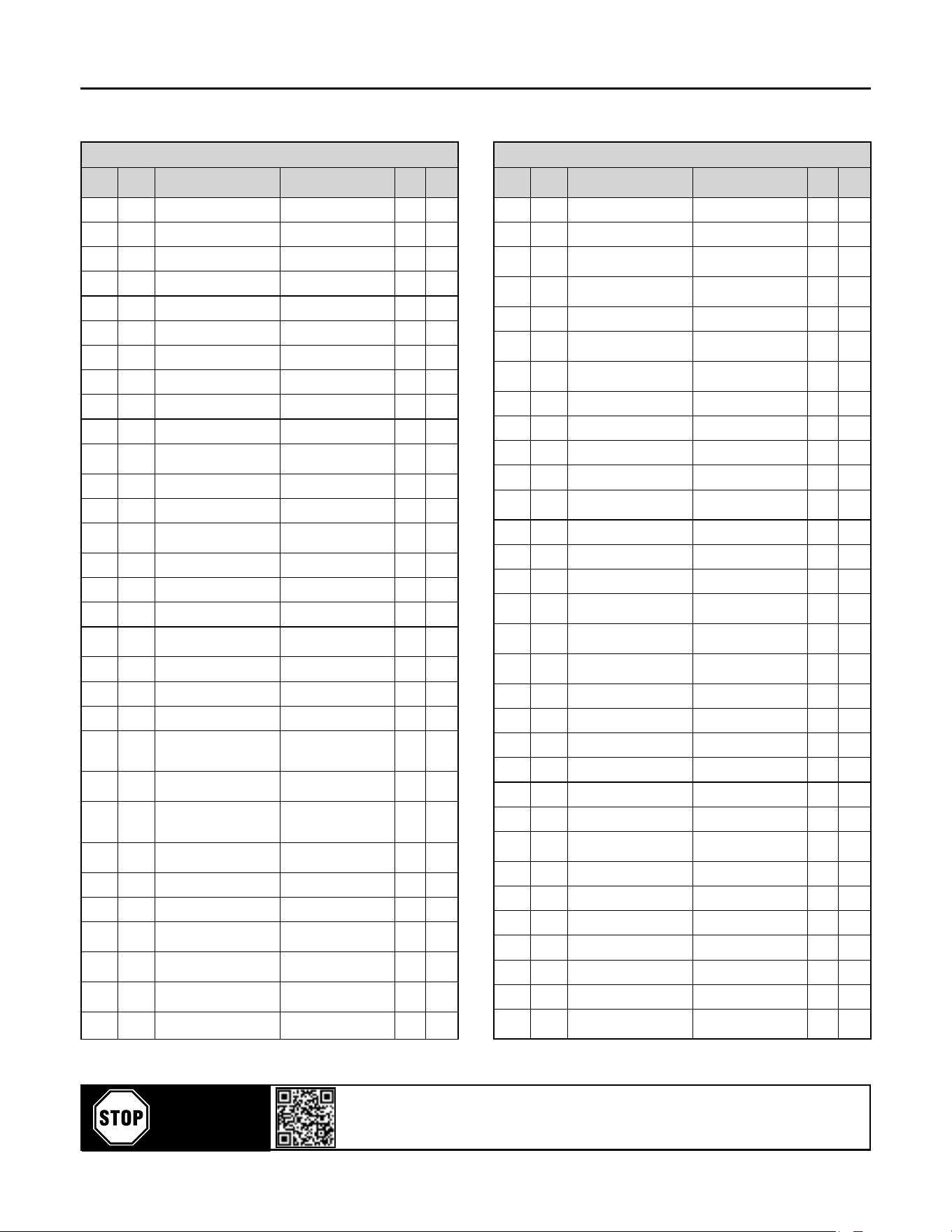
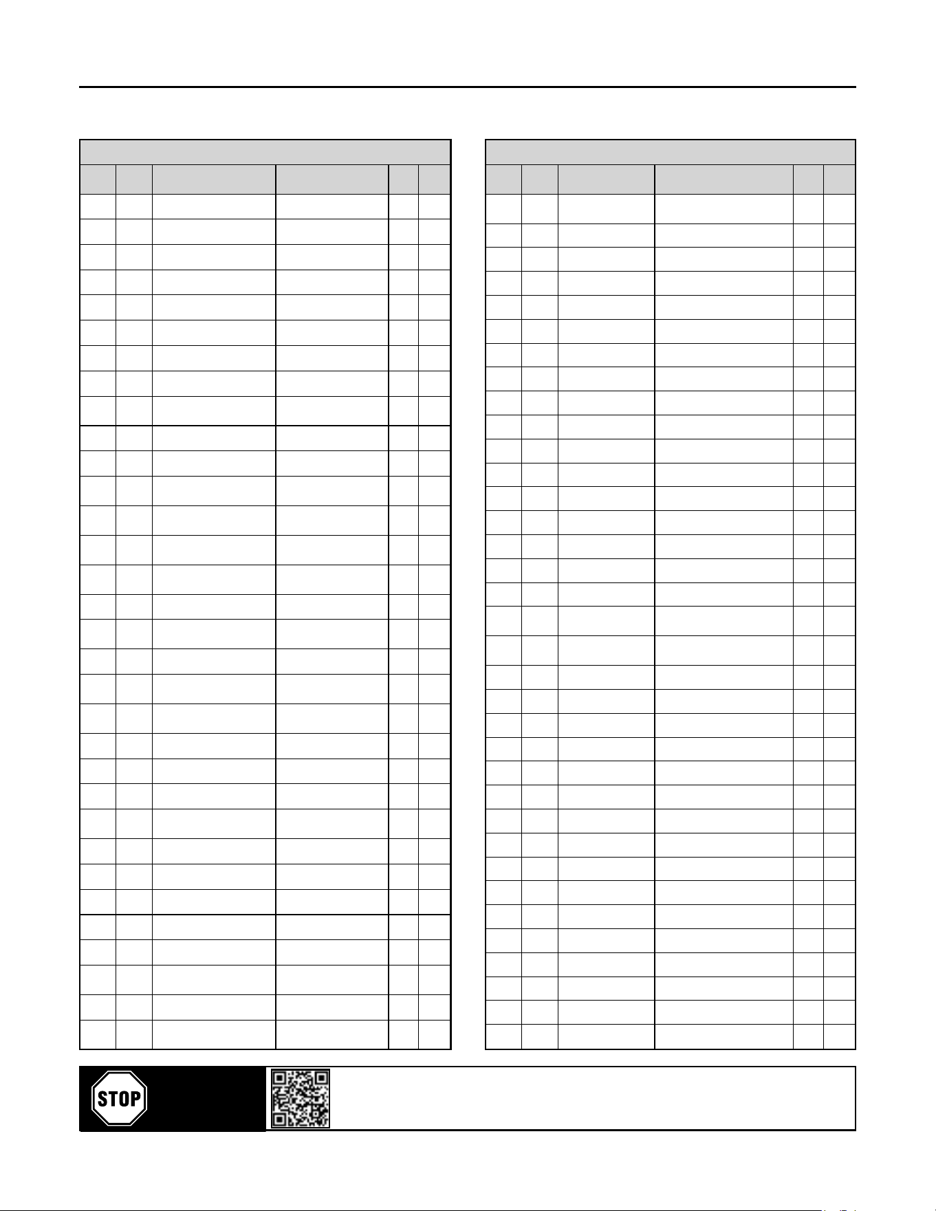
8.1 - ED & Spare Part List FDRCF1150030
PART LIST
DWG
SIZE
ITEM
NO.
PART NO. DESCRIPTION REV QT Y.
1 MK30E-CAB CABINET BASE 1
2 MK30E-CON CONDENSER 1
3 M-FAN-0075 FAN BLADE 1
4 M-GRL-0075 FAN GRILL 1
5 M-FMT-0075-115-1-60 FAN MOTOR 1
6 MK260E-BLT630 BOLT M6x30mm 8
7 MK110E-NT4 NUT M4 4
8 MK110E-BLT414 BOLT M4x14mm 1
9 MK110E-WHR20 WASHER 20x4,3x1,5 1
10 MK30E-EXC HEAT EXCHANGER 1
11 MK30E-IHE
INSULATION OF HEAT
EXCHANGER
1
12 MK260E-RCD 1/2" RECORD 1
13 M-DBV-0200 DRAIN BALL VALVE 1
14 MK150E-RDC
REDUCTION 3/8"
- 1/4"
1
15 MK170E-CHV CHECK VALVE 2
16 MK170E-T1/4 1 / 4" T CONNECTOR 1
17 MK170E-NIP1/4 1 / 4" NIPPLE 2
18 MK150E-FIT6
1 / 4" - 6mm
FITTINGS
3
19 M-SLV-0150-115 SOLENOID VALVE 1
20 N/A N/A -
21 M-CMP-0035-115-1-60 COMPRESSOR 1
22 MK40E-CEC
COMPRESSOR
ELECTRICAL BOX
COVER
1
23 M-CSR-0035-115-1-60
COMPRESSOR START
RELAY
1
24 M-COP-0035-115-1-60
COMPRESSOR
OVERLOAD
PROTECTOR
1
25 M-CSC-0035-115-1-60
COMPRESSOR START
CAPACITOR
1
26 MK30E-WSR18 WASHER 18x7x1mm 4
27 MK30E-NT6 NUT M6 4
28 MK30E-ELK-Y
COMPRESSED AIR
FILTER KIT (Y)
1
29 MK30E-ELK-X
COMPRESSED AIR
FILTER KIT (X)
1
30 MK170E-EWF
90* 1 / 4" - 6mm
ELBOW
1
31 MK30E-CPG COUPLING CLAMP 4
PART LIST
DWG
SIZE
ITEM
NO.
PART NO. DESCRIPTION REV QT Y.
32 MK30E-CNK-NPT CONNECTION CIT 2
33 MK30E-ORG O-RING 4
34 MK30E-EXS
HEAT EXCHANGER
SUPPORT STEEL
1
35 MK260E-RDC
REDUCTION 1 / 2"
- 1 / 4"
1
36 MK90E-GFD GASKET FOR DRAIN 1
37 MK30E-FIE-X
COMPRESSED AIR
FILTER ELEMENT (X)
1
38 MK30E-FIE-Y
COMPRESSED AIR
FILTER ELEMENT (Y)
1
39 MK30E-CRT CABINET REAR TOP 1
40 MK30E-CAI CABINET INSIDE 1
41 MK35E-FTT-T TEE FITTING 1
42 MK60E-BLT48 BOLT M4x8 8
43 MK260E-STC
SETTING THE
CONNECTION
1
44 M-BYV-0100 EXPANSION VALVE 1
45 M-DRI-0200 DRYER-DEHYDRATOR 1
46 M-FNS-0200 FAN ON/OFF SWITCH 1
47 MK260E-PCP
PLASTIC CONTROL
PANEL
1
48 MK130E-DPI-115
DIGITAL
CONTROLLER
1
49 M-STU-6000
CABINET STUD AND
NUT
8
50 MK90E-BLT412 BOLT M4x12 18
51 MK30E-COP CONTROLLER PANEL 1
52 MK260E-CG11 CABLE GLAND PG11 1
53 MK260E-RNT8 RIVET NUT M8 4
54 MK30E-CLT CABINET LEFT 1
55 MK30E-CBR CABINET RIGHT 1
56 M-CHN-6000
CABINET HANDLE
(NEW)
2
57 MK30E-CSG CABINET STRIPPING 2
58 MK30E-CAT CABINET TOP 1
59 M-FAS-6000 CABINET FASTENER 8
60 MK90E-CSP CABLE STRAP 3
61 MK90E-RVT3,5 RIVET Ø3,5 25
62 MK130E-PWC POWER CABLE 1
63 MK60E-RTA2
ROTOLOCK
ADAPTOR2
2
Scan or go to website hosted below:
www.eatoncompressor.com/warranty
Warranty only valid by following conditions expressed in the Warranty Statement section of this Air Dryer Manual.
YOU MUST
REGISTER TO
ACTIVATE
WARRANTY
Flexzilla Pro Energy Ecient Refrigerated Air Dryers
20
8.1 - ED & Spare Part List
FDRCF1150058
39
59
42
40
56
10
51
38
33
57
60
41
54
37
31
36
35
53
58
44
55
32
50
46
43
40
67
24
25
62
20
A
A
30
29
21
67
45
64
28
43
27
63
18
26
19
65
23
61
22
13
16
11
17
14
15
1
12
52
3
4
48
10
2
5
8
9
49
7
47
6
Scan or go to website hosted below:
www.eatoncompressor.com/warranty
Warranty only valid by following conditions expressed in the Warranty Statement section of this Air Dryer Manual.
YOU MUST
REGISTER TO
ACTIVATE
WARRANTY
Flexzilla Pro Energy Ecient Refrigerated Air Dryers
21
8.1 - ED & Spare Part List FDRCF1150058
PART LIST
DWG
SIZE
ITEM
NO.
PART NO. DESCRIPTION REV Q TY.
1 MK60E-CAB CABINET BASE 1
2 MK60E-CON CONDENSER 1
3 M-FAN-0150 FAN BLADE 1
4 M-GRL-0150 FAN GRILL 1
5 M-FMT-0150-115-1-60 FAN MOTOR 1
6 MK260E-BLT630 BOLT M6x30 4
7 MK110E-NT4 NUT M4 4
8 MK110E-BLT414 BOLT M4x14mm 1
9 MK110E-WHR20
WASHER
Ø20xØ4,3x1,5
1
10 MK90E-RVT3,5 RIVET Ø3,5 9
11
M-CMP-0035-115-1-60-H
COMPRESSOR 1
12 MK50E-CEC
COMPRESSOR
ELECTRICAL BOX COVER
1
13 M-CSC-0035-115-1-60
COMPRESSOR START
CAPACITOR
1
14
M-COP-0035-115-1-60-H
COMPRESSOR
OVERLOAD PROTECTOR
1
15 M-CSR-0035-115-1-60
COMPRESSOR START
RELAY
1
16 MK150E-BLT840 BOLT M8x40 4
17 MK260E-WHR22
WASHER
Ø22xØ8,5x2,5
4
18 MK60E-EXC HEAT EXCHANGER 1
19 MK60E-IHE
INSULATION OF HEAT
EXCHANGER
1
20 MK60E-RTA2
ROTOLOCK
ADAPTOR2
1
21 M-SLV-0150-115 SOLENOID VALVE 1
22 M-DBV-0200 DRAIN BALL VALVE 1
23 MK260E-ELW2 ELBOW 2 1
24 MK70E-RTA3
ROTOLOCK
ADAPTOR3
1
25 M-BYV-0100 EXPANSION VALVE 1
26 M-DRI-0200 DRYER-DEHYDRATOR 1
27 MK90E-CPT1 CUPPER T1 1
28 M-FNS-0200 FAN ON/OFF SWITCH 1
29 MK90E-TDP ADAPTOR T 1
30 M-HPS-0200
HIGH PRESSURE
SWITCH
1
31 MK60E-CNK1 CONNECTION CIT1 1
32 MK60E-ELK-X
COMPRESSED AIR
FILTER KIT (X)
1
PART LIST
DWG
SIZE
ITEM
NO.
PART NO. DESCRIPTION REV QTY.
33 MK60E-ELK-Y
COMPRESSED AIR FILTER
KIT (Y)
1
34 N/A N/A -
35 MK60E-CPG COUPLING CLAMP 5
36 MK60E-ORG O-RING 5
37 MK60E-CNK2-NPT CONNECTION CIT2 2
38 MK60E-CAI CABINET INSIDE 1
39 MK60E-CRT CABINET REAR TOP 1
40 MK90E-BLT412 BOLT M4x12 8
41 MK60E-BLT48 BOLT M4x8 2
42 M-STU-6000 CABINET STUD AND NUT 8
43 MK170E-CHV CHECK VALVE 1
44 MK90E-GFD GASKET FOR DRAIN 1
45 MK170E-EWF 90* 1 / 4" - 6mm ELBOW 1
46 MK260E-RDC REDUCTION 1 / 2" - 1 / 4" 2
47 MK60E-COP CONTROLLER PANEL 1
48 MK260E-PCP PLASTIC CONTROL PANEL 1
49 MK130E-DPI-115 DIGITAL CONTROLLER 1
50 MK60E-FIE-X
COMPRESSED AIR FILTER
ELEMENT (X)
1
51 MK60E-FIE-Y
COMPRESSED AIR FILTER
ELEMENT (Y)
1
52 MK260E-RNT8 RIVET NUT M8 1
53 MK60E-CLT CABINET LEFT 4
54 M-CHN-6000 CABINET HANDLE (NEW) 4
55 MK60E-CSG CABINET STRIPPING 2
56 M-FAS-6000 CABINET FASTENER 8
57 MK90E-CSP CABLE STRAP 1
58 MK60E-CBR CABINET RIGHT 1
59 MK60E-CAT CABINET TOP 4
60 MK90E-BLT615 BOLT M6x15 1
61 MK260E-CG11 CABLE GLAND PG11 1
62 MK130E-PWC POWER CABLE 1
63 MK150E-RDC REDUCTION 3/8" - 1/4" 1
64 MK170E-T1/4 1 / 4" T CONNECTOR 1
65 MK170E-NIP1/4 1 / 4" NIPPLE 2
66 N/A N/A -
67 MK150E-FIT6 1 / 4" - 6mm FITTINGS 3

Scan or go to website hosted below:
www.eatoncompressor.com/warranty
Warranty only valid by following conditions expressed in the Warranty Statement section of this Air Dryer Manual.
YOU MUST
REGISTER TO
ACTIVATE
WARRANTY
Flexzilla Pro Energy Ecient Refrigerated Air Dryers
22
9. COMPONENTS LOCATION
All main components located into dryer idened with labels as listed below.
CAUTION: Due to manufacturer design, some components out of the list are not installed into the dryer.
Electrical components:
Accessories:
A01: Control circuit transformer
A02: Power circuit transformer
A10: ON warning light
A11: OFF warning light
A20: Drain solenoid valve
A30: Crankcase heater
A31: Electrical resistor
A40: Electrical capacity
EV3: Digital Controller (Digi-Pro)
A50-3: Energy saving device 3 (ESD3)
Relays:
K01: Compressor motor relay
K10: Fan motor relay
K20: Drain mer or Bekomat (oponal)
K30: Temperature Controller
Switches:
S01: Main switch
S02: Start push buon
S03: Stop push buon
S10: Fan pressure control
S11: High-low pressure security control
S12: High pressure security control
S13: Low pressure security control
S20: Refrigerant temperature control
S21: Air temperature control
Motors:
M01: Refrigerant compressor motor
M10: Fan motor
Thermal protecons:
P01: Refrigerant compressor thermal overload
P10: Fan motor thermal overload
Fuses protecons:
See complete idencaon into electrical sketch
included in dryer
F--: Transformer protecon
F--: Fan protecon
F--: Compressor relay protecon
F--: Transformer protecon
F--: Drain protecon
F--: Fan relay protecon
Refrigerant components:
G01: Liquid receiver
G02: Refrigerant dryer
G03: Expansion valve
G04: Liquid separator
G05: Hot gas bypass valve
G06: Refrigerant solenoid valve
G10: Water cooled condenser
G11: Water control valve
G20: Refrigerant evaporang pressure gauge
G21: Refrigerant evaporang temperature gauge
Compressed air components:
H01: Air inlet prelter
H11: Drain lter
H12: Pneumac drain valve
Terminal boxes:
B01: Main terminal box
B11: Refrigerant terminal box
B12: Free of potenal terminal box

Scan or go to website hosted below:
www.eatoncompressor.com/warranty
Warranty only valid by following conditions expressed in the Warranty Statement section of this Air Dryer Manual.
YOU MUST
REGISTER TO
ACTIVATE
WARRANTY
Flexzilla Pro Energy Ecient Refrigerated Air Dryers
23
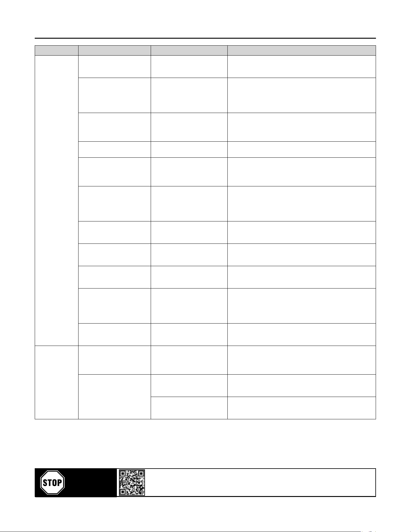
Problem Possible Cause Repair Comments
Dryer is switched
on, indicator
light is lit but
the refrigerant
compressor does
not turn on.
The connecon has inverted
phases.
Invert two phases. 3-phase dryers are equipped with a phase controller to avoid the
fans from turning in the opposite direcon.
Refrigeraon unit is not
funconing.
Check refrigeraon compressor. Several factors can cause compressor failure. A qualied
refrigeraon technician needs to check all the electrical and
refrigerant circuit and controls.
The refrigerant high pressure
protecon has tripped.
The refrigerant safety high
pressure switch has tripped.
The dryer is protected against excessively high refrigerant
pressure. If the condenser eciency has reduced, the switch will
trip. Manually reset the switch.
In case of water cooled
condensers, check the water
control valve.
Excessive ambient
temperature.
Be sure that dryer is working in
temperatures lower than the
designed condions. Designed
condions and correcon
factors are described in this
manual.
A high ambient temperature may cause the refrigerant system to
operate at higher than normal pressures. Results will be higher
than normal evaporator temperature. Important: adequate
air circulaon around the dryer, and proper venlaon in the
equipment room should guarantee a low enough ambient
temperature.
Dryer is switched
on, but the
refrigerant
compressor does
not turn on.
Excessive temperature on
crankcase of compressor.
Allow me for compressor to
cool down. May be a possible
incorrect adjustment of hot
gas bypass valve or shortage of
refrigerant.
Compressor is protected against overly high temperatures of the
crankcase by a thermal switch.
Excessive compressed air inlet
temperature.
Be sure that dryer is working
in temperatures lower than
designed condions.
The dryer is designed for working in calculated condions (see
descripon in this manual). If condions are exceeded, the dryer
will be overowed, dew point will go up and protecng devices
can switch o.
Clogged condenser ns or
clogged water condenser.
Possible high crankcase
temperature.
Possible loss of phase.
Possible low voltage causing
overload trip.
Possible failed compressor.
Clear ns of water condenser of
all obstrucons.
The clogged ns in the condenser will restrict the air passage
and reduce the refrigeraon capacity, causing high temperature
in the evaporator. Same will occur if water condenser is clogged
with mud or dirt. Air condenser and water condenser should be
periodically checked and cleaned. Protect water circuit by an
adapted lter.
Too much compressed air
ow.
Check actual ow through the
dryer.
This dryer is designed for a maximum air ow at design
condions. If too much air is pumped into the dryer, water
removal capacity may not be sucient, resulng in liquid
carryover down stream. Check the rated output the air
compressor.
Faulty electrical wiring. Inspect the circuit. The compressor-on light should be wired into the refrigerant
compressor circuit. See wiring diagrams in this manual.
One electrical protecon has
tripped.
Reset the protecon or replace
the blown fuse.
The dryer is protected against high amp draw by fuse and/or
overload relay that can trip in case of need. Reset or replace fuse
once, but do not persist if it trips again, request assistance from a
qualied refrigeraon contractor.
Dryer is switched
on but the fan is
not running.
Fan has to run if refrigerant
high pressure reaches upper
set point.
Check that compressor air ows
through the dryer.
Check that fan blades are free
to move.
Check the fan pressure switch.
Fan operates automacally to keep refrigerant pressure below
the maximum value. The fan can stop if pressure is under the
recommended seng.
When
compressor
starts, it vibrates
a lot and makes
mechanical
noise.
Compressor is slugging liquid
refrigerant at start up.
Be sure the preheang period of
at least 2 hours is respected.
Refrigerant may move between receivers when refrigerant
compressor is stopped and not heated, especially if stopped for
a long me.
This migraon may cause liquid shock (slugging) in valves
specially on large dryers containing more refrigerant.
10. Troubleshoong
Scan or go to website hosted below:
www.eatoncompressor.com/warranty
Warranty only valid by following conditions expressed in the Warranty Statement section of this Air Dryer Manual.
YOU MUST
REGISTER TO
ACTIVATE
WARRANTY
Flexzilla Pro Energy Ecient Refrigerated Air Dryers
24
Problem Possible Cause Repair Comments
Water in system. Compressed Air Inlet and
outlet connecons are
reversed.
Check inlet and outlet
connecons.
This dryer is designed for air ow in one direcon only. Inlet and
outlet direcons are idened on the dryer.
Drain system is clogged or
inoperave.
Restore a free ow of water
condensate. Check water
evacuaon.
Drain system is on med solenoid valve, pneumacally assisted
which has to be adjusted in accordance with values listed in this
manual. The solenoid valve includes a strainer that has to be
periodically checked and cleaned. Membranes of pneumacally
assisted drain have to be checked or replaced every 6 months.
Bypass system is open. Check the valves. Important: Bypass piping should be installed around the dryer so
the dryer can be isolated for service without shung down the
air supply. During dryer operaon, valves must be set so all air
goes into the system. Check ghtness of the bypass system.
Free moisture remains in pipe
lines.
Blow out the system. Before the dryer is rst started all free moisture should be blown
out of the system.
Excessive air ow. Check actual ow through the
dryer.
This dryer is designed for a maximum air ow. If too much air
is pumped into the dryer, water removal capacity may not be
sucient, resulng in liquid carry over downstream. Check the
rated ow of the air compressor.
Excessive free moisture. Check the separator and drain
system and compressor aer
cooler ahead of the dryer.
In some systems there may be an accumulaon of free moisture
in the line ahead of the dryer. If this moisture is pumped into
the dryer intermiently, the water removal capacity may not be
sucient. A water separator should be installed in the line before
the dryer.
Excessive compressed air inlet
temperature.
Be sure that dryer is working
lower than designed condions.
The dryer is designed to work for calculated design condions.
Should the condions be exceeded, the dryer will be overowed,
dew point will go up and protecng devices can switch o.
Clogged condenser ns. Clear ns of all obstrucons. The clogged ns in the condenser will restrict air passage and
reduce refrigerant capacity causing water downstream. Fins
should be periodically checked and cleaned.
Shortage of refrigerant. Fix the leak and add a charge of
refrigerant.
Loss of refrigerant will cause improper funconing. A qualied,
refrigeraon specialist should perform the necessary repairs, or
factory should be contacted if the unit is under warranty.
Refrigeraon system is not
funconing.
Check to be certain refrigerant
compressor is running.
To check if the compressor is running, check compressor on light.
It is possible for the fan to be operang but not the compressor.
Compressor not running can be caused by several factors. A
qualied refrigeraon technician should check all refrigerant and
electrical controls.
Excessive pressure dew point. Readjust refrigerant evaporang
pressure.
The refrigerant pressure adjustment should be done by a
qualied refrigeraon engineer. This is a very sensive device and
incorrect sengs may create other failures.
High pressure
drop.
Excessive compressed air ow
or too low air inlet pressure.
Check actual pressure and ow
through the dryer.
This dryer is designed for a maximum air ow. If too much air
is pumped into the dryer, water removal capacity may not be
sucient, resulng in liquid carryover downstream. Check the
rated ow of the air compressor.
Freeze up. Check that compressor room
ambient.
Frosng of the lines is an indicaon that controls are set too low.
The following should be done by an experienced refrigeraon
technician.
Fan switch could have failed in
closed posion keeping fan on.
Controls may be adjusted in the elds by means of the hot
gas bypass valve. This is to be done by a qualied refrigerant
technician.
Scan or go to website hosted below:
www.eatoncompressor.com/warranty
Warranty only valid by following conditions expressed in the Warranty Statement section of this Air Dryer Manual.
YOU MUST
REGISTER TO
ACTIVATE
WARRANTY
Flexzilla Pro Energy Ecient Refrigerated Air Dryers
25
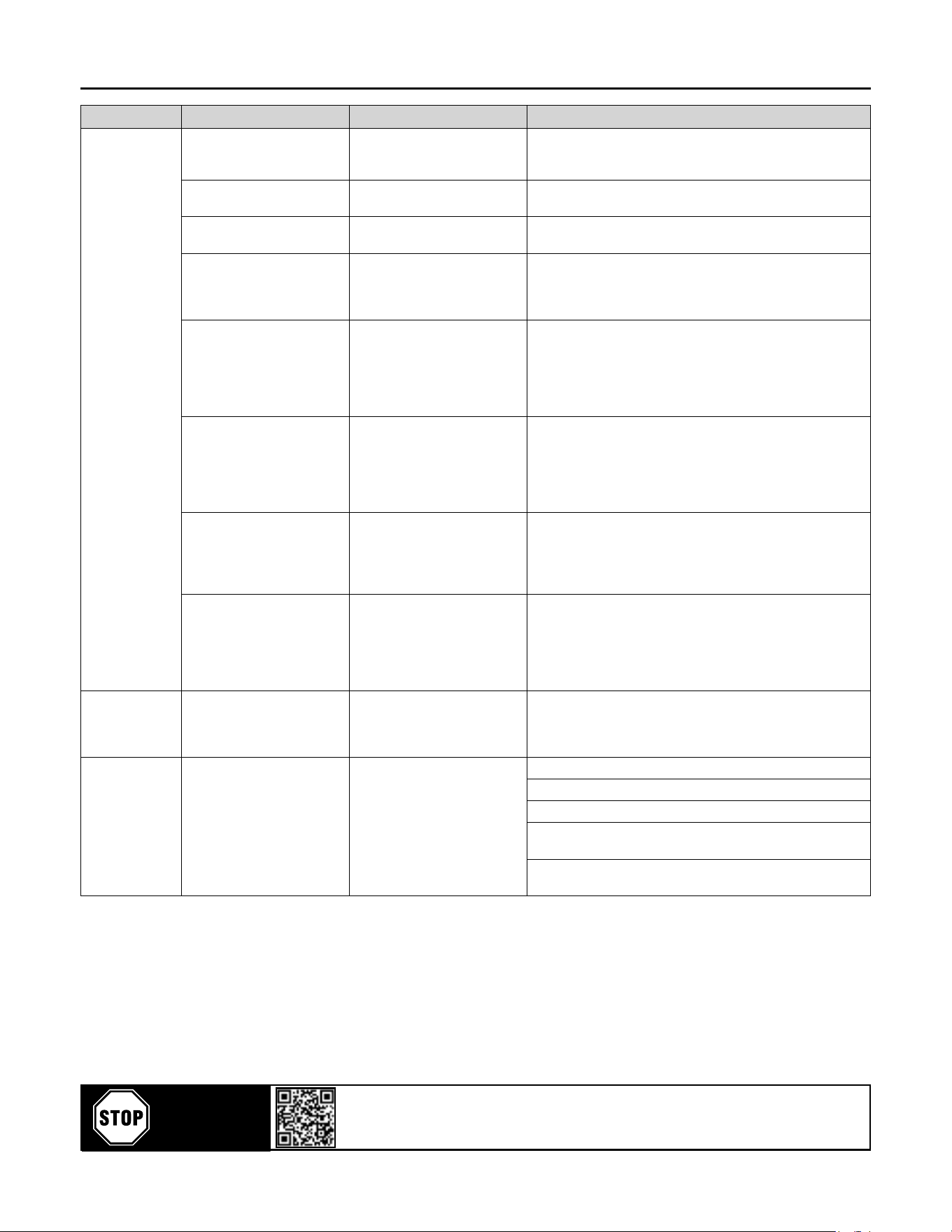
Problem Possible Cause Repair Comments
The unit will not
run or cycles o
and on.
Clogged heat exchanger. Clean heat exchanger with a
reverse air ow.
Dryer is supposed to be used with compressed air free of any
aggressive contaminants. Some contaminaon may require extra
maintenance of the heat exchanger.
Line disconnect switch is open. Close the start or disconnect
switch.
If the dryer is not operang, check the disconnect switch or
circuit breaker to be certain it is on.
Fuse or breaker is open. Replace fuse or reset breaker. The fuse to the power line should be checked and replaced if
needed. Never replace a burnt fuse with an oversized fuse.
Faulty refrigerant compressor
or controls.
Determine the cause and make
correcon.
Failure of compressor to run may be caused by several factors.
A qualied refrigeraon specialist should check all electrical and
refrigeraon controls, or factory should be contacted if unit is
under warranty.
Excessive compressed air inlet
temperature.
Designed condions and
correcon factors are described
in this manual.
Be sure that dryer is working in
ambient temperatures below
designed condions.
The dryer is designed for working into calculated design
condions. Should the condions be exceeded, the dryer will be
overowed, dew point will go up and protecng devices may trip.
Excessive ambient
temperature.
Designed condions and
correcon factors are described
in dryer.
Be sure that dryer is working
lower than designed condions.
A high ambient temperature may cause the refrigerant system to
operate at higher than normal pressures. Results will be a higher
than normal evaporator temperature.
Important: There should be adequate air circulaon around the
dryer, and proper venlaon in the equipment room should
guarantee a low enough ambient temperature.
Clogged condenser ns. Clear ns of all obstrucons. The clogged ns in the condenser will restrict the air passage and
reduce the refrigeraon capacity, causing high temperature in the
evaporator. Fins should be periodically checked and cleaned.
Low refrigerant level. Fix the leak and add a charge of
refrigerant.
Loss of refrigerant will cause improper funconing. Dryers are
equipped with a temperature switch which maintains the amount
of refrigerant to maintain proper cooling of the compressor.
A shortage of refrigerant may cause sucon line to become
very hot, causing the temperature switch to trip. A qualied
refrigeraon specialist should perform the necessary repairs.
Error sign
occurs on digital
temperature
control device.
The dew point is too low or
too high.
Check refrigerant gas and make
sure that the working condions
are within the correct range.
If there is not enough refrigerant gas or if the working
temperature and inlet temperatures are very high, the dew point
will increase.
Drain failure. Back pressure or reducon of
drain port.
Replace the drain(s). Open
drain to atmosphere (no back
pressure) - if hose / pipe is used
to carry the drain somewhere
else, keep or enlarge the
diameter.
Max. drain hose length aer the dryer must not exceed 30 feet.
Max. drain hose height from the dryer must not exceed 9 feet.
The drain port size should not be reduced.
There should not be any ng that may cause pressure drop
such as valves, elbow, tees, etc. on the drain connecon.
Drain should be at atmospheric pressure at all mes. Any back
pressure will result in failure and malfuncon.

26
Flexzilla Pro Energy Ecient Refrigerated Air Dryers
Warranty Statement Refrigerated Air Dryers
WEEMS GLOBAL® (and each of its subsidiaries) makes the following warranes:
Standard Warranty: That each air dryer is free from defects in material, workmanship, and parts for 1 year from the
date of delivery. This Standard Warranty includes full 1 year of warranty labor from an authorized technician. Eaton
compressor is not responsible for downme during warranty service. If downme is necessary, it is at the owner’s
discreon, obligaon, and expense, to have a redundant compressor. Parts shipped for warranty repairs shall only
include ground freight charges for the rst 90 days of the warranty period, thereaer owner is responsible for all freight
charges of parts shipped for for warranty. Any and all express shipping charges of warranty parts would be at the owner’s
expense.
*Standard warranty has no obligaon to maintain warranty status, warranty will expire one year from date of delivery.
Please see available opons below to extend your warranty.
Extended Warranty: WEEMS GLOBAL will extend your standard 1-year warranty to full 3 years when you opt to register
for the extended warranty plan and purchase one Airbase dryer lter replacement kits per year along with following all
roune maintenance set forth. Parts shipped for warranty repairs shall only include ground freight charges for the rst 90
days of the warranty period, thereaer owner is responsible for all freight charges of parts shipped for warranty. Any and
all express shipping charges of warranty parts would be at the owner’s expense. Standard technical assistance is provided
at no charge during and aer the standard warranty period.
Warranty Shall not apply and WEEMS GLOBAL shall not be responsible nor liable for:
• Roune service
• Downme, nor any damages incurred during installaon
• Consequenal damages such as but not limited to cost of loss of business, product damage, or down me
• Acts of nature, over abuse, malicious destrucon, improper maintenance, undersized equipment
• In the case the product has been disconnued at any point the *Limited lifeme warranty will last ve years
past the disconnue date. WEEMS GLOBAL has discreon to substute parts with current model for the
ve-year duraon.
• Deviaon from operang instrucons or specicaons
• Any malfuncon caused by failure or improper use and/or maintenance of other components manufactured
by others
• Labor charges for repairs or maintenance
• Normal wear and tear parts
Warranty shall be voided under the following condions: Exposing electrical components to rain or water, or installing
the unit in a hosle environment such as acid vapors or any causc or abrasive maer that may be ingested into the
pump, or installing the unit in an enclosed area where lack of cooling venlaon is present, such as in boiler or equipment
rooms where the ambient air exceeds 100F.
Further exclusions include failure to fully and completely follow the guidelines set forth in the manual. Of specic note is
environments where ne dust is common, such as granite, marble or concrete plants, the compressor MUST be installed
in a separate area with its own dedicated venlaon. FAILURE TO PROVIDE THIS DUST FREE OPERATING AREA VOIDS THE
WARRANTY.
Parts used for warranty purposes must be supplied by Eaton Compressor. Warranty work should be performed by an
Eaton Compressor approved Technician. If any maintenance (other than roune maintenance) is performed by a non-
approved Technician, wrien pre-approval must be obtained from Eaton Compressor, to prevent voiding this warranty.
Failure to fully comply with this warranty and fully comply with the manual instrucons will void this warranty.
Tech Support: 877.283.7614
eecve as of Jan. 2020
FLEXZILLA, The Flexzilla Stylized X and the color CHARTREUSE as applied to the body of the air compressor are all registered trademarks of Weems Industries, Inc.
Silencer™ Patented