en
en Operator‘s manual
Pressure Tank Unit
09067-20.960.04
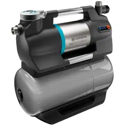
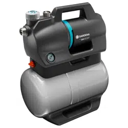
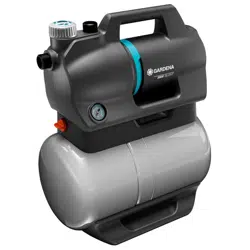
5600 SilentComfort Art. 9067
6300 SilentComfort Art. 9068
2
Fold-out Page width 5 mm less: 205 mm
A1
A2
A3
A4
A5
M
A
X
M
A
X
M
A
X
Art. 1411
Art. 1418
3
Fold-out Page width 5 mm less: 205 mm
A8A7
A9
A10
A11
O1
O2
M2
M3
M4
S1
M1
T1
h
h
1
1
3
2
Art. 1723
Art. 1724
A4
A
5
AG
A
7
A
6
A
G
A
7a
A
d
A
z
min. 2,2 l
8
9
min. 1,8 m
A
6
12
11
16
16
d
21
1
2
9
13
8
14
13
14
16
d
17
15a
15b
15c
16
18
19
v
8
9
20

4
en 5600 SilentComfort / 6300 SilentComfort pressure tank unit
Translation of the original instructions.
1 Terms and abbreviations .....................................................................................................................6
2 Safety instructions ..............................................................................................................................7
2.1 Symbols on the product ........................................................................................................................................ 7
2.2 General safety instructions ..................................................................................................................................... 7
2.3 Additional safety instructions ................................................................................................................................. 8
3 Assembly............................................................................................................................................10
3.1 Selecting the installation location ......................................................................................................................... 10
3.2 ScrewingthePTUontoasurface[Fig.A6/A7/A8] ................................................................................................ 10
3.3 Connecting the suction side ................................................................................................................................ 10
3.3.1 Types of connection systems ..................................................................................................................... 11
3.3.2Connectingthesuctionhose[Fig.A9] ........................................................................................................ 11
3.4 Connecting the hose to the pressure side ............................................................................................................ 11
3.4.1Connectingthepressurehose[Fig.A10] .................................................................................................... 12
3.4.2 Connect the pressure hose via the GARDENA combi system ..................................................................... 12
3.4.3 Parallel connection of pressure hoses ......................................................................................................... 12
3.5 Connectingthesoilmoisturesensor(optional)[Fig.A11]...................................................................................... 12
4 Commissioning ..................................................................................................................................13
4.1 Initial commissioning ........................................................................................................................................... 13
4.1.1 Commissioning the PTU for the first time .................................................................................................... 13
4.1.2 Selecting a language .................................................................................................................................. 13
4.2 Starting/stoppingthepumpunit[Fig.O1/O2] ...................................................................................................... 13
4.2.1 Starting the pump unit ................................................................................................................................ 13
4.2.2 Stopping the pump unit .............................................................................................................................. 14
4.2.3 Max. flow values ......................................................................................................................................... 14
4.3 Installing a pre-filter (accessory) ........................................................................................................................... 14
4.4 Using sprinklers ................................................................................................................................................... 14
5 Functions ...........................................................................................................................................15
5.1 How the pressure tank unit works ....................................................................................................................... 15
5.2 Adjustable pressure ranges ................................................................................................................................. 15
5.3 Power Boost ....................................................................................................................................................... 15
5.4 Bluetooth® .......................................................................................................................................................... 15
5.5 Timers and watering schedules ........................................................................................................................... 15
5.5.1 Timer ......................................................................................................................................................... 16
5.5.2 Irrigation schedules (exclusive app function) ............................................................................................... 16
5.5.3Optionalsoilmoisturesensor(Art.1867) .................................................................................................... 16
5.6 Safe-pump .......................................................................................................................................................... 16
5.6.1 Automatic restart ........................................................................................................................................ 16
5.7 Reminder ............................................................................................................................................................ 16
5.8 Direct start .......................................................................................................................................................... 16
5.9 Safety 17
5.9.1 Leakage detection ...................................................................................................................................... 17
5.9.2 Maximum run time ..................................................................................................................................... 17
5.10 Factory settings ................................................................................................................................................. 17
6 Operation ...........................................................................................................................................18
6.1 Operatingthepressuretankunitviaapp.............................................................................................................. 18
6.2 Operatingthepressuretankunitwiththekeys ..................................................................................................... 18
6.2.1 Symbols on the screen ............................................................................................................................... 18
6.2.2 Explanation of the control panel: ................................................................................................................. 18
6.2.3 Menu navigation ......................................................................................................................................... 18
6.2.4 Power saving function ................................................................................................................................ 19
6.2.5 Child lock ................................................................................................................................................... 19
7 Messages on the screen ....................................................................................................................20
7.1 Status indicators .................................................................................................................................................. 20
7.2 Informative messages .......................................................................................................................................... 20
7.3 On-screenmessagesrelatedtoBluetooth®function: ........................................................................................... 21

5
8 Settings ..............................................................................................................................................22
8.1 Timer ............................................................................................................................................................... 22
8.2 Mode (adjustable pressure ranges) ...................................................................................................................... 22
8.2.1 Mode selection ........................................................................................................................................... 22
8.2.2 Individual mode .......................................................................................................................................... 23
8.3 Power Boost ....................................................................................................................................................... 23
8.4 Bluetooth ............................................................................................................................................................. 24
8.4.1 Switching Bluetooth on and off ................................................................................................................... 24
8.4.2 Pairing (connecting a mobile device for the first time) .................................................................................. 24
8.4.3 Deleting devices ......................................................................................................................................... 24
8.5 Brightness ........................................................................................................................................................... 25
8.6 Language ............................................................................................................................................................ 25
8.7 Reminder ............................................................................................................................................................ 26
8.8 Direct start .......................................................................................................................................................... 26
8.9 Safety 26
8.9.1 Leakage ..................................................................................................................................................... 27
8.9.2 Max. run time ............................................................................................................................................. 27
8.10 Factory settings ................................................................................................................................................. 27
9 Maintenance ......................................................................................................................................28
9.1 Cleaningthepressuretankunit[Fig.M1] ............................................................................................................. 28
9.2 Flushing the pump unit ........................................................................................................................................ 28
9.3 Checkingtheairpressureinthereservoir[Fig.M1] .............................................................................................. 28
9.4 Cleaningthefilter[Fig.M2] .................................................................................................................................. 29
9.5 Cleaningthecheckvalve[Fig.M3/M4]................................................................................................................. 29
10 Storage .............................................................................................................................................30
10.1Decommissioningandstorage[Fig.S1] ............................................................................................................. 30
11 Troubleshooting ...............................................................................................................................31
11.1Releasingtheimpeller[Fig.M3/T1] .................................................................................................................... 31
11.2 Error messages ................................................................................................................................................. 31
11.2.1 Messages related to errors 1, 2, 10 and 11 .......................................................................................... 32
11.2.2 Errors 1 and 2 ...................................................................................................................................... 32
11.2.3 Error 10 and 11 .................................................................................................................................... 33
11.3 Error table for the PTU ....................................................................................................................................... 34
12 Technical data ..................................................................................................................................36
13 Accessories/spare parts ..................................................................................................................37
14 Warranty/Service .............................................................................................................................38
14.1 Product registration ........................................................................................................................................... 38
14.2 Service .............................................................................................................................................................. 38
15 Disposal ...........................................................................................................................................39
15.1 Disposal of the pressure tank unit ...................................................................................................................... 39
16 Annex ...............................................................................................................................................40
16.1 Assignment of trademarks ................................................................................................................................. 40
16.2 EC Declaration of Conformity ............................................................................................................................ 40
17 Performance characteristics ..........................................................................................................41

6
1 TERMS AND ABBREVIATIONS
• PTU: This abbreviation stands for pressure tank unit. This is the name for the entire device incl.
pump unit and pressure tank.
• Pump unit: Component mounted on the pressure tank that connects to the hose lines and pumps
the water.
• Automatic mode:Automaticswitchingonandoofthepumpunitduetowaterbeingdrawnand
the associated drop in pressure in the pressure tank.
• Pressure tank: The pressure tank is mounted under the pump unit and can store water under
pressure and release it when removed.
→ Sentences preceded by an arrow are operating instructions.
en
7
2 SAFETY INSTRUCTIONS
2.1 Symbols on the product
→ Read the operator’s manual.
2.2 General safety instructions
DANGER!
Electric shock
Risk of injury from electrical current.
→ The product must be supplied with power via a residual-current device (RCD) with a rated tripping
current of no more than 30 mA.
→ Disconnect the product from the mains before decommissioning it, servicing it or replacing parts.
When doing so, the power outlet must be within your eld of vision.
2.2.1. Intended use
This product can be used by children aged from eight years and above and persons with reduced
physical, sensory or mental capabilities or without experience and knowledge provided they are
supervised or have been instructed on using the product safely and understand the hazards invol-
ved. Children must not play with the product. Cleaning and user maintenance must not be perfor-
med by children without supervision unless they are eight years of age or older and are supervised.
The use of this product by young people under the age of 16 is not recommended.
The GARDENA PTU is intended for pumping ground and rainwater, tap water and chlorinated water
in private gardens and allotments.The GARDENA PTUs 5600/6300 Bluetooth® Art. 9067/9068
are part of an irrigation system along with the Bluetooth® app.
The user interface is intended for manual operation via display and control keys, as well as via Blue-
tooth® with a mobile device.
The product is not intended for commercial use.The product is not intended for permanent opera-
tion.
2.2.2. Safe operation
The water temperature must not exceed 35°C.The PTU must not be used when there are people in
the water.
2.2.3. Transport uids
The GARDENA PTU may only be used to pump water.
DANGER!
Risk of injury
→ Donotpumpsaltwater,dirtywater,corrosive,highlyammableorexplosivesubstances(for
examplepetrol,paran,nitro-cellulosethinners),oils,fueloilorfoodstus.
2.2.4. Extension cable
When using extension cables, they must comply with the minimum cross-sections in the following
table:
Voltage Cable length Cross-section
230–240V/50Hz Up to 20 m 1.5 mm²
230–240V/50Hz 20–50 m 2.5 mm²
en

8
2.3 Additional safety instructions
DANGER!
Risk of cardiac arrest
Thisproductgeneratesanelectromagneticeldduringoperation.Thiselectromagneticeldmay
aectthefunctionalityofactiveorpassivemedicalimplants(e.g.pacemakers),whichmayresultin
serious injury or death.
→ Consult your doctor and the manufacturer of your implant before using this product.
→ After using the product, disconnect the mains plug from the mains socket.
2.3.1. Additional electrical safety instructions
→ Set up the PTU so that it is stable and cannot be submerged.
→ Set up the PTU so that it is protected against falling into the water.
Set up the PTU at a safe distance (min. 2 m) from the medium to be pumped.
→ An approved personal safety switch can be used as an additional safety feature for the residual-
current device (RCD).
→ Askaqualiedelectricianaboutthis.
→ The information on the rating plate must match the mains data.
→ Unplug the PTU before anyone enters a swimming pool connected to it.
If the mains connection cable of this machine is damaged, it must be replaced by the manufacturer
oritsaftersalesserviceteamorasimilarlyqualiedpersontoavoiddanger.
→ Protect the mains plug and mains connection cable from heat, oil and sharp edges.
→ Do not carry the PTU by the cable or use the cable to remove the plug from the wall socket.
→ Do not expose the PTU to rain or use the PTU in a wet or humid environment.
→ Check the connection cable at regular intervals.
→ Always conduct a visual inspection of the PTU (especially the mains connection cable and mains
plug) before use.
A damaged PTU must not be used.
It is essential to have the PTU checked by GARDENA Service if it is damaged.
Electricalmodicationsmayonlybecarriedoutbyaqualiedelectrician.
→ DisconnectthePTUfromthemainsbeforelling,removalormaintenance.
→ Take heed of the generator manufacturer‘s warnings when using our PTU with a generator.
en

9
2.3.2. Additional personal safety instructions
DANGER!
Risk of suocation
→ Small parts can easily be swallowed.
→ Keep small children away when you assemble the product.
DANGER!
Risk of injury from hot water
The pumped water is pressurised and can cause injury if it directly strikes the body or eyes.
If there is no water supply on the suction side, the water in the PTU may heat up and the hot water
produced could cause injury if leakage occurs.
→ Disconnect the PTU from the mains and let the water cool down.
→ Donotopencapsorttingswhenthewaterishot.
Ensure that the water supply on the suction side is present before restarting.
→ If hoses or pipes are exposed to the sun, they can become very hot.
→ Do not use the product with untied hair.
→ Do not connect the PTU to the drinking water supply.
→ To prevent the pump unit from running dry, make sure that the suction hose end is always in the
pumped medium.
→ SlowlyllthePTUuptotheoverow(min.2.2l)withwaterbeforestartingiteachtime.
→ WhenllingthePTUwithwater,makesurethatnohosesorconsumersareconnectedtothePTU
and that the PTU is generally level.
Make sure that the hoses are not kinked.
→ Sand and other abrasive substances cause faster wear and reduced pump unit performance.
Ifwatercontainssand,useapumppre-lter.
→ Pumping contaminated water, for example containing stones, pine needles etc., can damage the
pump unit.
→ Do not pump heavily contaminated water.
en

10
3 ASSEMBLY
DANGER!
Risk of injury
Risk of injury due to unintentional startup.
→ Disconnect the plug from the mains socket.
3.1 Selecting the installation location
• The surface must be low-vibration (e.g. do not place on metal sheets or plastic tanks) to ensure quiet
operation.
• Ifinstalledbelowwaterlevel,ashut-odevicemustbeinstalledtopreventunwantedwaterloss.
• Theinstallationlocationmustbelevel,rmandprovidethePTUwithasecurefooting.
• It must be located at least 2 m away from open water.
• ThePTUmustbeinstalledinadrylocationwithsucientventilationandwithnoriskofsubmersion.
• It must be at least 5 cm away from walls.
• Set up the PTU so that you can place an appropriately sized receptacle for emptying the PTU under
the drain screw
20
.
• TopreventwaterleakingontotheoorduringtheemptyingprocessandtoallowthePTUunittobe
emptied fully, it must be possible to tilt the PTU forwards by approx. 80° towards the drain screw
20
.
• If possible, install the PTU higher than the surface of the water you wish to pump.
• Ifthisisnotpossible,installavacuum-resistantshut-ovalvebetweenthepumpunitandthesuc-
tion hose.
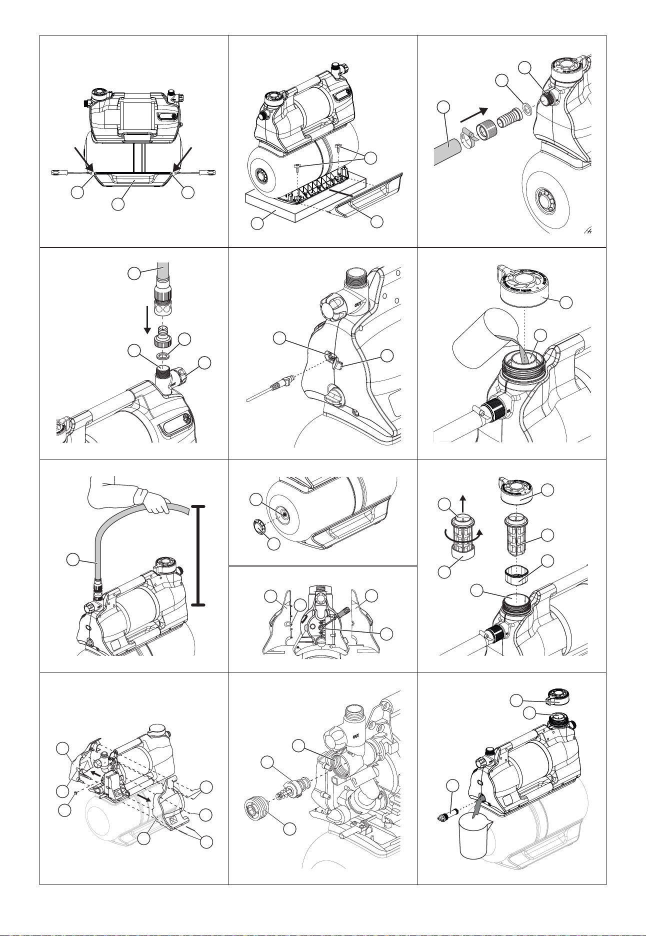
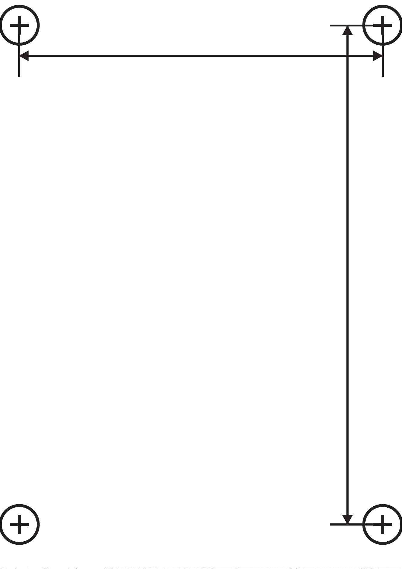
3.2 Screwing the PTU onto a surface [Fig.A6/A7/A8]
ThePTUcanoptionallybescrewedinplace.A1:1drilltemplate[Fig.A6]isprovidedatthebackofthe
operating manual (261 mm x 190 mm).We recommend using four screws 7.5 x 45 (concrete screw) or
8x45(woodscrew)forinstallationontheoor.Hexheadscrewsarerecommended.
1. Drilltheholepatternofthe1:1drillingtemplate[Fig.A6]onyourselected(solid)surface
3
.
2. Useascrewdriver(max.5mm)andinsertitintothesidehole
h
of one cover
1
[Fig.A7].
3. Press the screwdriver to release the snap-on hook (2 hooks per cover
1
).
4. While holding down the snap-on hook, pull the side cover
1
othebaseofthepressurevessel.
Use the same procedure for the second cover.
5. Screw the PTU to the solid surface
3
by hand using four hex head screws
2
(not supplied).
6. Push the two side covers
1
back onto the base of the pressure vessel until the snap-on hooks
snap into place.
3.3 Connecting the suction side
The suction side connection
5
isttedwitha33.3mm(G1“)externalthread.Thisconnectionislabel-
led with (In).
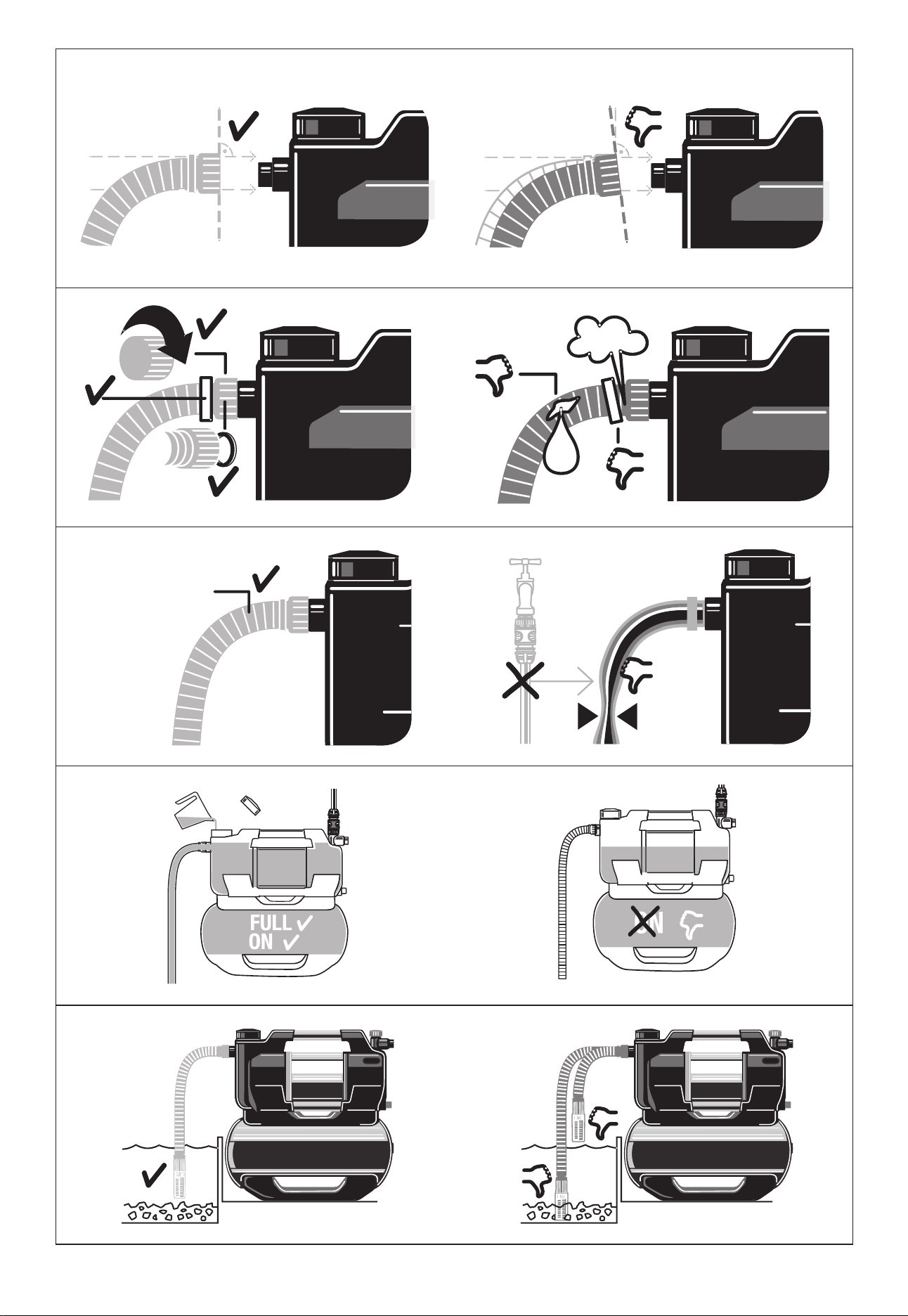
Theconnectionpieceonthesuctionsidemayonlybetightenedbyhand[Fig.A2].
Asuctionhoseorpermanentpipingwithabackowpreventer[Fig.A9]mustbeusedtopreventmal-
functions and ensure a short suction resumption time.
Drawing air into the suction system may result in a loss of function and increased noise.
→ Connect the suction hose carefully.
→ Check the seal at regular intervals and replace it if necessary.
Do not use modular water hose components on the suction side.
en

11
A vacuum-resistant suction hose must be used on the suction side [Fig.A3]:
• Forexample,theGARDENAsuctionsetArt.1411/1412/1418
• or the GARDENA fountain suction hose Art. 1729.
• Connect suction hoses
4
without a threaded connection to the connection on the suction side
usingasuctionhoseconnectionpiece(forexampleArt.1723/1724),ensuringitisairtight.
3.3.1 Types of connection systems
Designed for a at gasket:
Including all GARDENA suction sets made of plastic. No thread sealing tape is required.
Ensurethattheatgasket
G
isinsertedintothesuctionhosettingandisundamaged.
Designed for thread sealing tape (Teon):
Ifyouusedierentconnections,usesealingtapeonthemalethreadoftheconnections.
→ Anincorrectsealingsystemmaycauseleaks/airingressandreducethesuctioncapacity.
→ Use the sealing system provided for this purpose.
3.3.2 Connecting the suction hose [Fig.A9]
1. Ensurethattheatgasket
G
isinsertedintothesuctionhosetting.
2. Screw the vacuum-resistant suction hose
4
onto the connection on the suction side (In)
5
so
thatitisairtight.Thesuctionhosettingmustbeinstalledstraight[Fig.A1].
3. Route the suction hose
4
so that it is straight and not twisted.
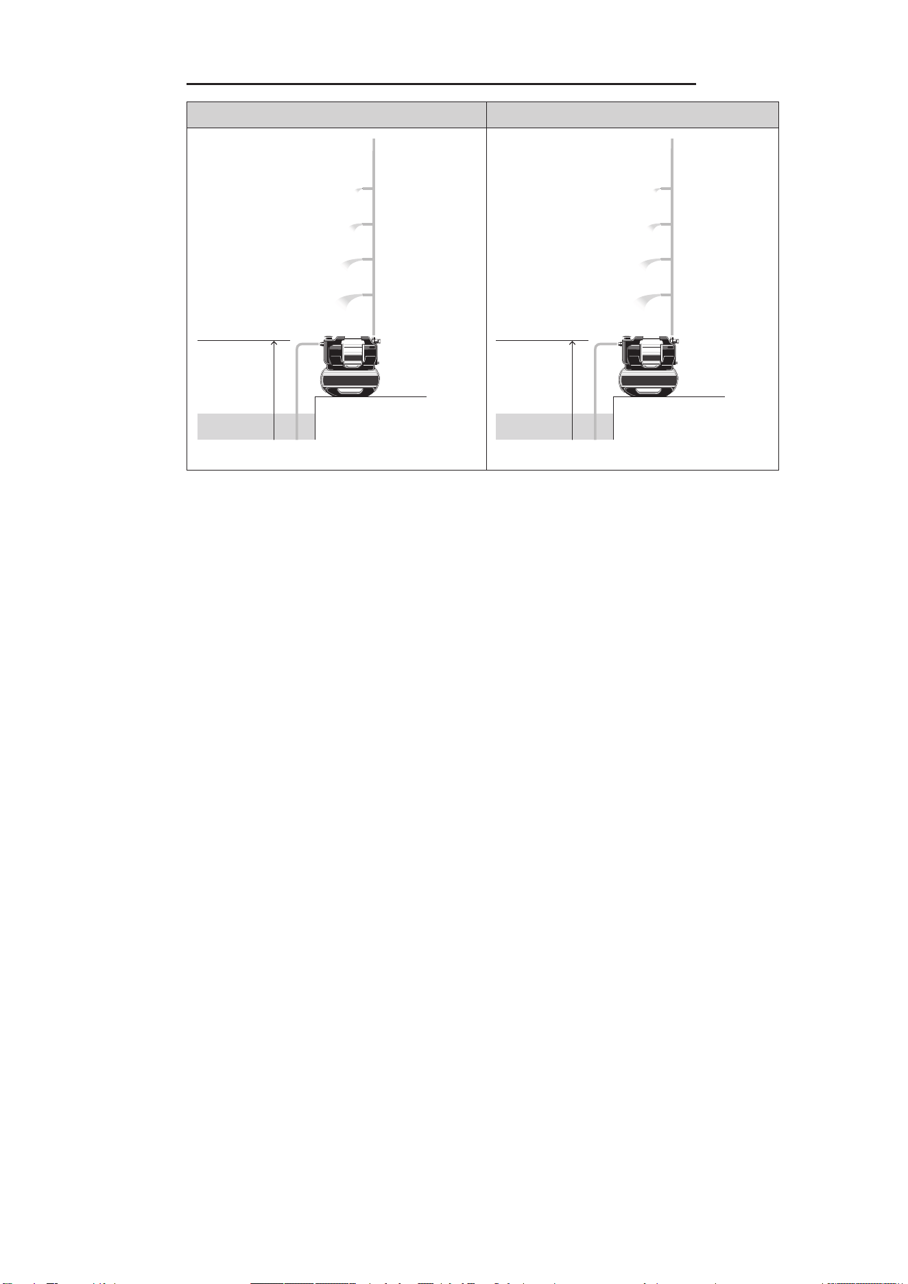
4. For suction heights above 3 m: Also secure the suction hose
4
(for example tie it to a wooden
peg).
This relieves the PTU of the weight of the PTU.
Ifthewaterhasverynecontamination,inadditiontotheintegratedlter,aGardena pump pre-lter
Art. 1730/1731 is recommended.
3.4 Connecting the hose to the pressure side
→ Usesuitableshut-ovalvesforpermanentinstallationonthepressureside.Thisisimportantfor
maintenance and cleaning work or for decommissioning, for example.
→ When permanently installing the PTU indoors for the domestic water supply, the PTU should not be
rmlyconnectedtorigidpipeswhenconnectingtothepipenetworkonthepressureside,instead
exiblehoselines(e.g.armouredhose)shouldbeusedinordertoreducenoiseandavoiddamage
to the pump unit due to pressure surges.
Toensuregoodventing,donotconnectthepressurehoseuntilthePTUhasbeenlled(see“4.2.1
Starting the pump unit”).
→ Therearetwoconnectionsonthepressureside,whichareequippedwitha33.3mm(G1“)exter-
nalthread:Onehorizontal(180°rotatable)andoneverticalconnection.Theseconnectionsare
labelled with (Out).
The unused connection must be closed with the plug cap
7a
.
The connection piece on the pressure side may only be tightened by hand. A xed pipe
must be installed at an upwards angle so that water can ow back into the pump unit on the
pressure side. Ecient use of the pumping capacity of the pump unit is achieved by con-
necting:
• 19mm(3/4“)hosesinconjunctionwiththeGARDENA pump connection set Art. 1752 or
• 25mm(1“)hoseswiththeGARDENA female quick thread coupling Art. 7109/quick coupling
hose connector Art. 7103.
Holdorxthepressurehoseverticallytopreventitkinkingattheverticalpumpoutlet.Laythehoseat
on the ground and ensure that there are no U-shaped rises in it or coiled hoses. The best way of all-
owing air to escape is for the pressure hose to be stretched out so that it runs upwards when viewed
en

12
from the PTU.
3.4.1 Connecting the pressure hose [Fig.A10]
Connect the pressure hose
6
to the connection on the pressure side
7
.Ensurethattheatgasket
G
isinsertedintotheconnectionpiece.Ifyouusedierentconnections,usesealingtapeonthemale
thread of the connections.
3.4.2 Connect the pressure hose via the GARDENA combi system
TheGARDENAcombisystemcanbeusedtoconnect19mm(³⁄₄“)/16mm(⁵⁄₈“)and13mm(¹⁄₂“)
hoses.
Hose diameter Pump connection
13 mm (¹⁄₂"“) GARDENA pump connection
set
Art. 1750
16 mm (⁵⁄₈") GARDENA tap connector-
GARDENA hose connector
Art. 18222Art. 18216
19 mm (³⁄₄") GARDENA pump connection
set
Art. 1752
3.4.3 Parallel connection of pressure hoses
If more than two pressure hoses are connected in parallel, we recommend the use of:
• e.g., the GARDENA 2-way or 4-way distributor Art. 8193/8194
or the GARDENA 2-way valve Art. 940.These can be screwed directly onto the connections on the
pressure side
7
.
3.5 Connecting the soil moisture sensor (optional) [Fig.A11]
1. Make sure that charged batteries or rechargeable batteries are inserted in the sensor.
2. Place the soil moisture sensor in the watering area.
3. Opentheprotectivecover
d
.
4. Insert the sensor plug into the sensor connector
z
of the PTU.
en
13
4 COMMISSIONING
4.1 Initial commissioning
4.1.1 Commissioning the PTU for the rst time
→ Connect your PTU to the power supply.
The Welcome screen starts.
The Select language menu opens.
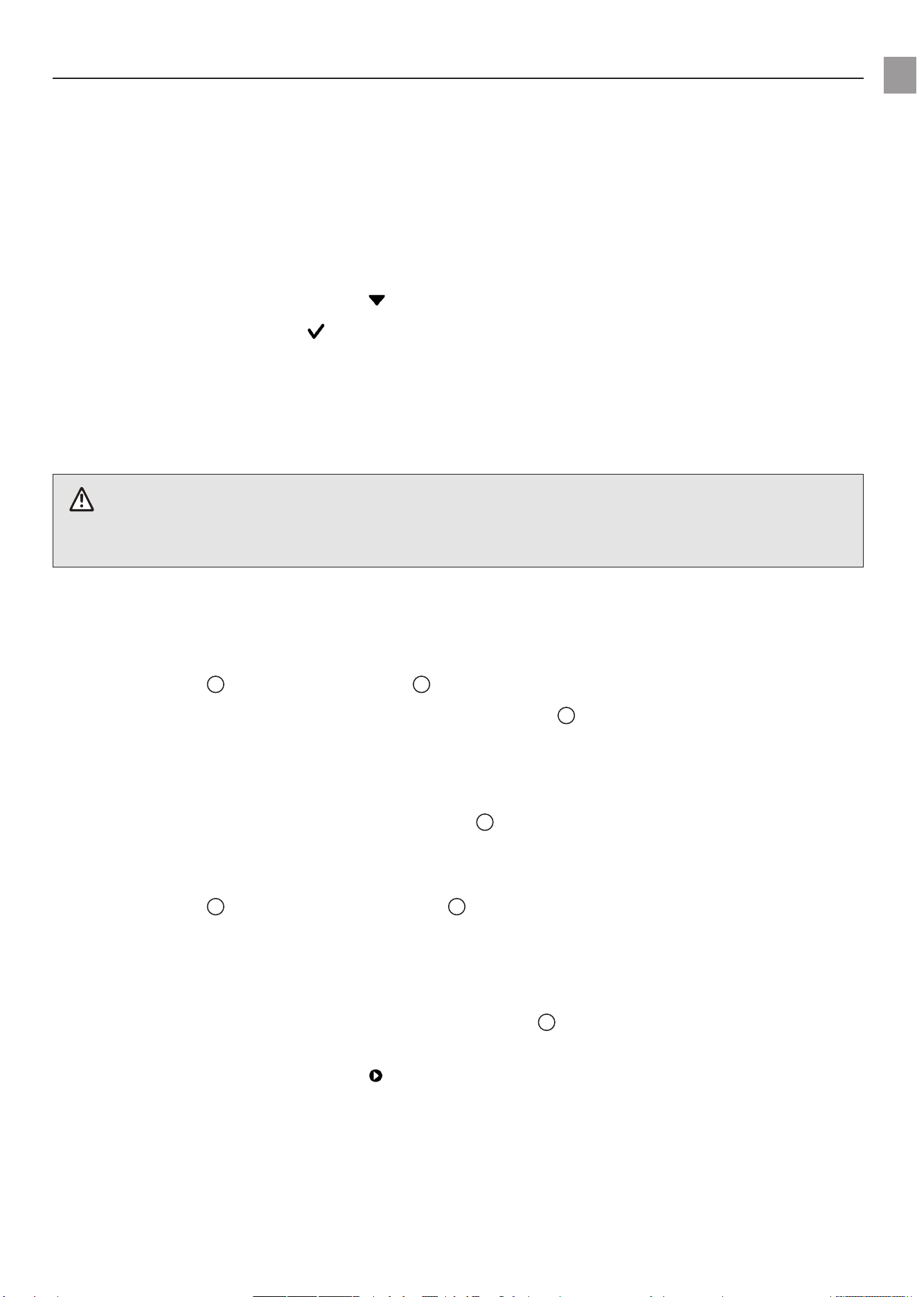
4.1.2 Selecting a language
1. To select a language, navigate with .
2. Conrmyourselectionwith .
The language is selected.
The status display is displayed.
3. Now start setting up and operating your PTU.
4.2 Starting/stopping the pump unit [Fig.O1/O2]
CAUTION!
Dry running of the pump unit
→ Makesurethatthepumpunitislledwithwateruptotheoverow(atleast2.2l)beforeyoustart
it.
4.2.1 Starting the pump unit
1. Connect the suction hose (In).
2. Remove the pressure hose (Out).
3. Screw the cap
8
ontothellingopening
9
by hand.
4. Slowlyaddatleast2.2lofwaterthroughthellingopening
9
until a stable water level is reached
thatislevelwiththesuctionconnection[Fig.A4].
5. If using a suction set with check valve: Fill the suction hose with water. This speeds up the priming
process.
6. Drain the residual water out of the pressure hose
6
before connecting it. This allows the air to
escape during the priming process.
7. Afterllingthepumpunit:Connectthepressurehose(Out)tothepumpunit.
8. Screw the cap
8
fullyontothellingopening
9
by hand (do not use any tools).
9. Openanyshut-ovalvesinthedeliveryline(wateringaccessories,waterstopetc.).Allconsumers
must be open as wide as possible.
10. Connect the power cable plug to a mains socket.
11. For high suction heights: Lift and hold the pressure hose
6
atleast1.8mabovethePTUduring
the priming process.
12. To start automatic mode, press the key(see“6Operation”).
The pump unit starts and delivers water after the priming process.
Note:
• Theprimingprocesscantakeuptoveminutes.
• Whenusingforthersttime,theremaybeabrief(approx.10seconds)increaseinnoiselevelnear
the tank.
en

14
If the pump is not pumping water after ve minutes:
1. Let the pump unit cool down.
2. Lookforpossiblecausesintheerrortables(see“11.2Errormessages”)and(see“11.3Errortable
for the PTU”).
3. Restart the pump unit.
4.2.2 Stopping the pump unit
To stop automatic mode, press the key.
4.2.3 Max. ow values
The pump unit has a bypass valve to enable short suction times. If the hose end is open without a
watering accessory or the hose diameters are very large, the valve may not be able to change from
suction to pump operation due to the hydraulic pressure conditions.
To take advantage of the full pumping power, you can then close the water outlet for about 1 second
while the engine is running (e.g. by kinking the hose). This allows the valve to take its correct position.
In standard applications with watering accessories such as sprayers and sprinklers, this is done auto-
matically.
4.3 Installing a pre-lter (accessory)
Ifapre-lteristoolong,itmaybeinstalledinadierentposition(forexamplehorizontally)ratherthan
vertically facing downwards.
4.4 Using sprinklers
Switchingthepumpunitonandoautomaticallymayresultinanunevenirrigationpatterndepending
ontheowrateofthesprinkler.Thiseectcanbecancelledbyactivatingthespecialfunction“Power-
boost”(see“8.3PowerBoost”).
en

15
5 FUNCTIONS
This chapter provides an overview of all the functions of your PTU. All adjustable functions can be
foundinthesettingsofyourPTU(see“8Settings”).
5.1 How the pressure tank unit works
Afterbeinglled,thepumpunitdrawsinwaterfromadepthofupto8mandpumpsitintothepres-
sure tank. This stores the water, which is pressurised by means of a pre-set air pressure and a separa-
ting membrane.
Thepumpunitstartswhenwaterisremovedandtheintendedcut-inpressureisreached(see“12
Technicaldata”)andstopsthellingprocessagainwhentheswitch-opressureisreached.This
meansthatsmallquantitiesofwatercanbepumpedoutofthepressuretankinanenergy-ecient
manner.Athighowrates,suchasforirrigation,however,thepressureuctuationsbetweentheon
andopressureareclearlyperceptible.Thiseectcanbecancelledbyactivatingthespecialfunction
“Powerboost”.
5.2 Adjustable pressure ranges
YoucansetthepressurerangeforyourPTUmanually(see“8.2Mode(adjustablepressureranges)”).
Youhavetheoptionofchoosingbetweentwopredenedpressurerangesoranindividuallydened
range:
Art. 9067 Art. 9068
ECO
Cut-in pressure
Cut-out pressure
1.5bar
2.6bar
1.5bar
2.6bar
Normal
Cut-in pressure
Cut-out pressure
1.8bar
3.3bar
1.8bar
3.3bar
Individual:
Cut-in pressure
Cut-out pressure
1.5–2.3bar
2.5–3.3bar
1.5–2.6bar
2.5–3.6bar
Note:Acut-outpressureofmorethan3.3barisonlypossibleatasuctionheightoflessthan5m.
5.3 Power Boost
ThePowerboostfunctionreliablydetectshighowrates(e.g.inasprinkler)andcontinuespumping
despitereachingtheswitch-opressure.Afterwateringhasbeencompleted(includingafollow-up
time), the PTU returns to the previously selected pressure mode, provided that the demand is only for
smallows(e.g.fortoiletushingordripirrigation).
5.4 Bluetooth®
TheBluetoothfunctionoersyouaconvenientwaytocontrolyourPTUusingtheGARDENABlue-
tooth®app.Todothis,youmustpairyourPTUwithyourmobiledevice(Android®oriOS®)viaBlue-
tooth®(see“8.4Bluetooth”).
5.5 Timers and watering schedules
InadditiontoswitchingyourPTUonandomanually,youcanalsoswitchitonandousingthetimer
function or watering schedules.
Note that when the consumer unit is open, the pressure tank drains after the timer has expired or at
theendofthewateringschedule,eventhoughthepumpunitisswitchedo.
en

16
5.5.1 Timer
The timer function allows you to set the desired run time of your PTU. You can choose between 1 and
99minutes.Assoonasthetimerhasexpired,yourPTUswitchesoautomatically.
5.5.2 Irrigation schedules (exclusive app function)
The Bluetooth app allows you to create, manage and delete watering schedules for your PTU. So it‘s
active and ready to draw water precisely when you need it. Please note that this feature is only availa-
ble via the Bluetooth app.
Note:
The PTU schedules are based on the last synchronised time (last Bluetooth connection). If the PTU is
disconnected from the mains for a long period of time, the time stored in the PTU pauses. To match
the stored time to the current time again, connect the PTU to a mobile device.
Tip:
→ Watering schedules can also be used to program rest times. To do so, set a schedule for the utili-
sation times.
→ Synchronise the time during commissioning in the spring.
The schedules are saved.
5.5.3 Optional soil moisture sensor (Art. 1867)
In addition to time-dependent control, there is also the option to take the soil moisture level into
account.Ifthereissucientsoilmoisture,wateringisskipped.Makesurethattherearecharged
rechargeable batteries or batteries in the soil moisture sensor.
5.6 Safe-pump
The PTU is equipped with the safe-pump function to protect it from damage during operation.
The safe-pump function is able to detect the following occurrences:
• Suction problems during commissioning
• Dry running (e.g. water source is depleted)
• Overheatingofthewater
• Engine overheating
• Warning about the risk of frost
• Mechanical faults (e.g. jammed or missing check valve)
Ifoneoftheseoccurrencesreachesacriticalpoint,asafetyswitch-oorwarningmessageistriggered
(see“11.2Errormessages”).
5.6.1 Automatic restart
Incaseofsuctionordryrunningproblems,anautomaticrestarttakesplaceafter1,5,12andnally
every 24 hours. In the case of saved watering schedules, a restart takes place at the beginning of the
next schedule.
5.7 Reminder
Usethereminderfunctiontoremindyourselfofthenextltercleaningbasedonoperatinghoursand
your own experience (local water pollution level).
5.8 Direct start
Withthe“Directstart“function,thePTUstartsassoonasitissuppliedwithpower.Thisfunc-
tionisparticularlysuitableforoperationwithatimerortheGARDENA“smartPoweradapter”(Art.
19095/19096).
en

17
5.9 Safety
Your PTU has two optional safety options.
5.9.1 Leakage detection
The leakage detection function can detect small leaks and thus prevent water loss. It ensures that your
PTUisautomaticallystoppedifapermanentlylowwaterowisdetected.Thisfeatureisdisabledby
default.
5.9.2 Maximum run time
Thefunction“Max.runtime”limitsthetimeofcontinuouswateroutputbyperformingasafetyswitch-
o,e.g.inthecaseofaburstgardenhose.Byusingthe“Max.runtime”function,itispossibletode-
ne how long the PTU can draw water continuously. As soon as the set time is reached, the PTU auto-
maticallystopsandthuseectivelyprotectsagainstincreasedwaterlossduetopossiblemajorleaksin
the piping system.
5.10 Factory settings
Use this function to reset your PTU to factory settings. This resets all of your settings, such as Blue-
tooth connections, schedules, maximum run time and other customisations.
Note:
If you want to reconnect your mobile device after deleting all settings, an error message appears.
→ Remove your PTU from the Bluetooth® settings of your mobile device to correct the error.
en
18
6 OPERATION
You can operate the GARDENA pressure tank units 5600 and 6300 via the device‘s own control panel
or conveniently via the GARDENA Bluetooth® app in conjunction with a mobile device.
6.1 Operating the pressure tank unit via app
The free GARDENA Bluetooth® app is available from the App Store (Apple) or Google Play.
OrscantheQRcode.
System requirements:
AtleastAndroid5.0/iOS13.X
1. Download the GARDENA Bluetooth® app from the App Store (Apple) or Google Play.
2. MakesurethatthereisacleareldofvisionbetweenyouandyourPTU.
3. SelectyourPTUintheappandfollowthestep-by-stepinstructions(see“5.4Bluetooth®”).
• The range depends on the mobile device.
• Depending on the device, a delay (1–5 seconds) of the display data can occur.
6.2 Operating the pressure tank unit with the keys
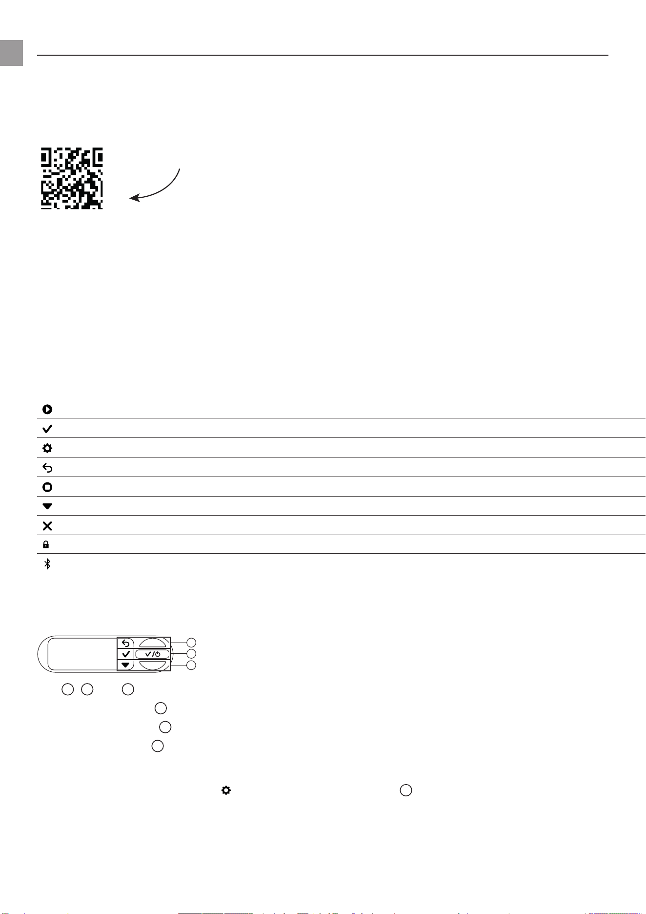
6.2.1 Symbols on the screen
Start
Conrm
Settings
Back
Stop
Scroll/changevalue
Cancel
Keys locked
Bluetooth
®
connected
Symbol ashes:
Pairingmode(see“8.4.2Pairing(Connectingamobiledeviceforthersttime)”)
6.2.2 Explanation of the control panel:
b
a
c
The
a
,
b
and
c
keysreectthethreeiconsonthedisplay:
• Use the upper key
a
to select the upper icon.
• Use the middle key
b
to select the middle icon.
• Use the lower key
c
to select the lower icon.
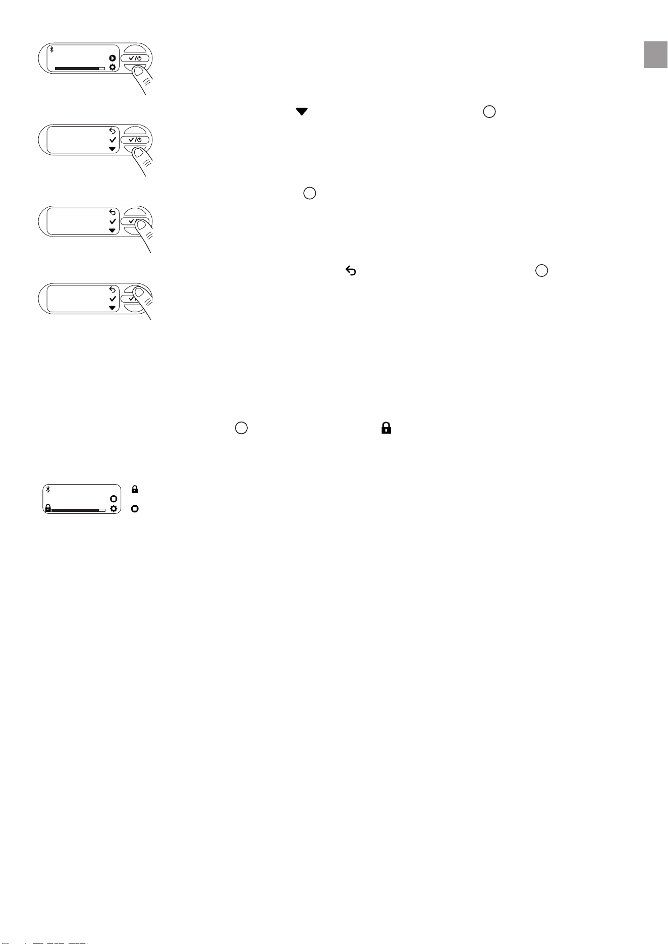
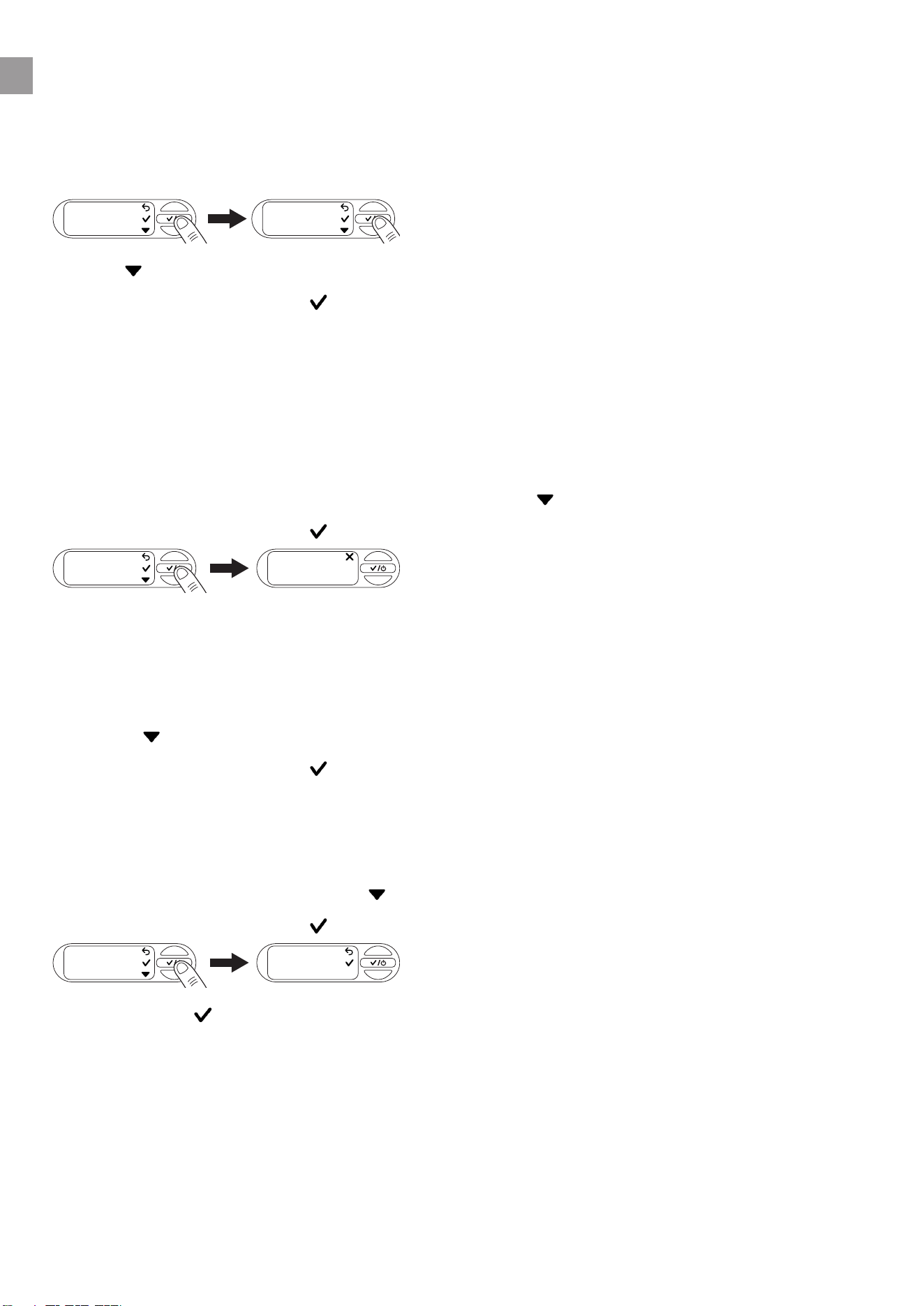
6.2.3 Menu navigation
→ To open the menu, select the icon by clicking the lower key
c
.
en
19
2,1 bar
OFF
→ To navigate through the menu, select the icon by clicking the lower key
c
.
Timer
→ To open a menu item, click the middle key
b
.
Timer
→ To exit the menu or selected submenu, select the icon by clicking the upper key
a
.
Timer
6.2.4 Power saving function
Thescreendimsafteroneminuteandturnsoafteranotherminute.
→ Press any key to turn the screen back on.
6.2.5 Child lock
→ Press and hold the middle key
b
for 5 seconds to lock ( ) or unlock the screen.
Watering can be stopped manually even if the screen is locked.
Example:
Watering
SCHEDULE
The screen is locked.
Stop watering manually.
en
20
7 MESSAGES ON THE SCREEN
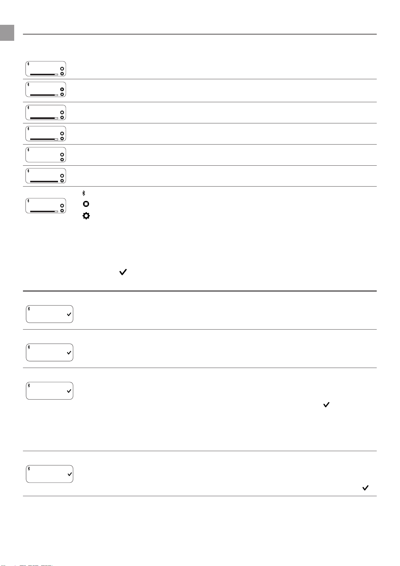
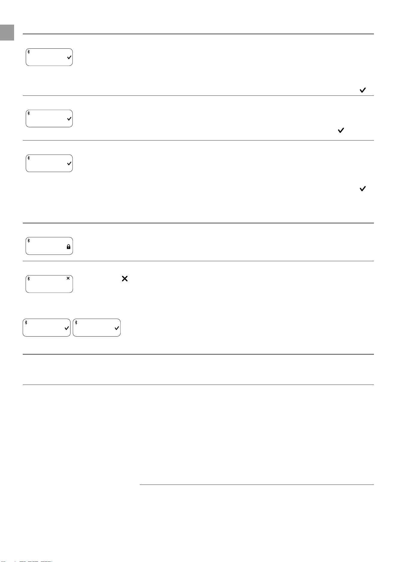
7.1 Status indicators
2,1 bar
ON
PTU in automatic mode - Pump unit currently started.
2,1 bar
OFF
Automaticmodeisswitchedo.
Water can be removed from the pressure tank.
2,1 bar
STANDBY
PTUinautomaticmode-Pumpunitiscurrentlyswitchedountilcut-inpressureis
undershot due to water extraction.
99:00 min
ON
PTUreadyforoperationforadenedperiodoftime-Afterthetimerhasexpired,
statusswitchesto“OFF”
Suction
Waterisdrawninuntilastableowisachieved.Aftercompletion(upto5minutes),
thesystemswitchestoON/READYstatus.
Power Boost
ON
ThePTUhasdetectedahighowrateandcontinueswateringdespitereachingthe
switch-opressure(whenthePowerBoostfunctionisenabled).
Watering
SCHEDULE
Bluetooth
®
connected
Stop watering manually.
To the settings
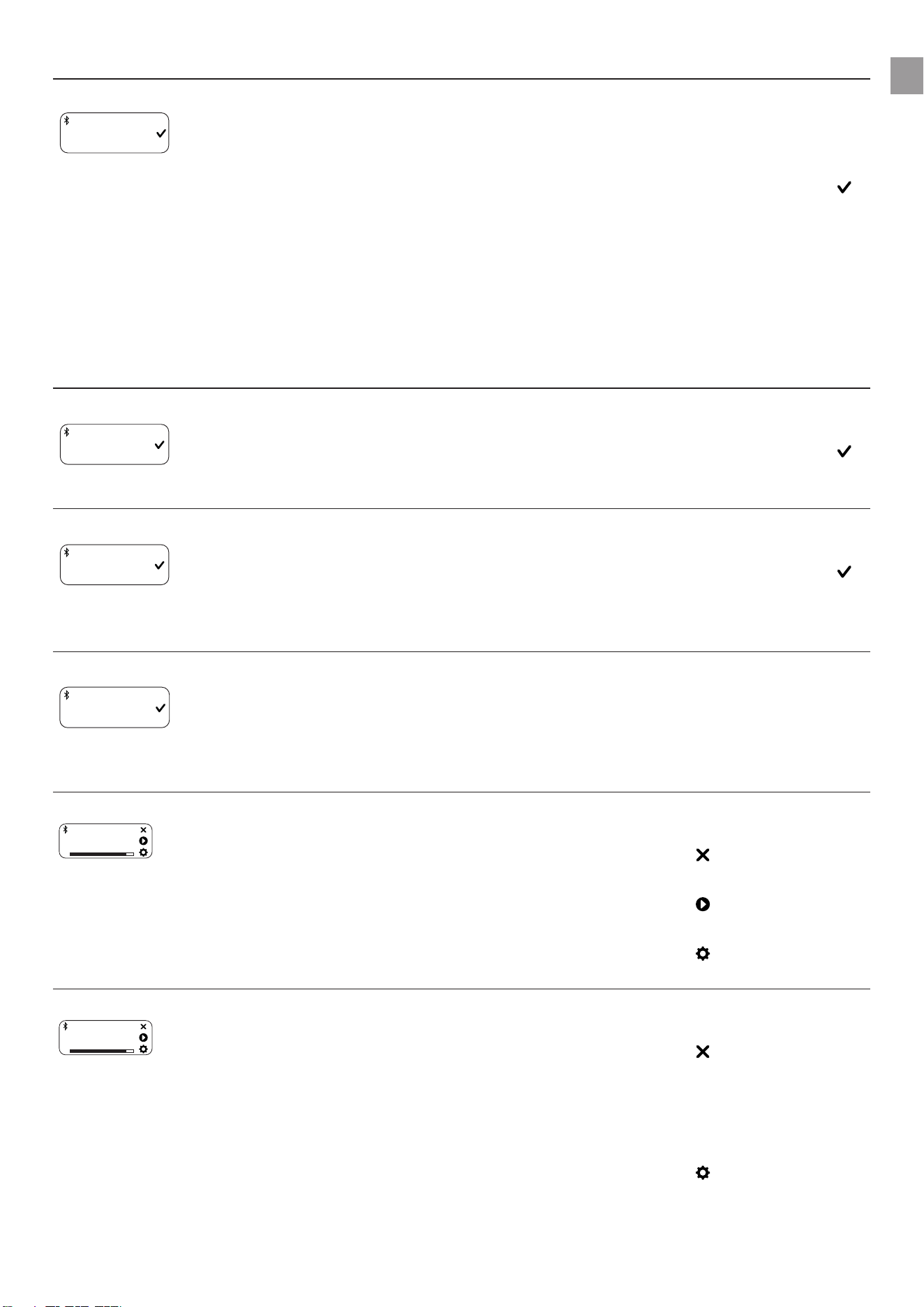
7.2 Informative messages
These messages provide you with information about possible hazards for the PTU at an early stage.
→ Look for the possible cause in the table below and resolve the problem.
→ Close the message with .
Message Possible cause Remedy
Risk of frost
INFO
Risk of fro
Your PTU has been exposed to
near-freezing temperatures in
the last few hours.
→ Decommission your PTU.
→ Store your PTU in a frost-
proof place.
Hot water
INFO
Hot water
Your PTU has a high operating
temperature.
→ Checkthewaterow.
→ If necessary, change the
location of your PTU.
Cleanlter
INFO
Clean filter
Your pre-set cleaning interval
has been reached.
→ Cleanthelter(see
“9.4Cleaningthelter
[Fig.M2]”).
→ Conrmwith to reset the
cleaning interval.
→ If necessary, adjust the
cleaninginterval(see“5.7
Reminder”).
Max. run time reached
INFO
Max. runtime
Your pre-set run time limit has
been reached.
→ If necessary, adjust the
max.runtime(see“5.9.2
Maximum run time”).
→ Close the message with .
en
21
Message Possible cause Remedy
Leakage stop
WARNING
Leakage stop
A leak has been detected. → Check all hoses and con-
nected devices for leaks
and replace them if neces-
sary.
→ Close the message with .
Note: Small consumers, such
as drip watering, can simulate
a leak. It may be necessary to
switchotheleakdetectionfor
such consumers.
7.3 On-screen messages related to Bluetooth®function:
Message Possible cause Remedy
Soil moisture too high
INFO
Soil moistur
The measured soil moisture is
higher than the previously set
value.
The watering cycle has been
skipped.
→ If necessary, adjust the soil
moisture sensor setting.
→ Close the message with .
Rain pause
INFO
Rainpause
The message appears when
the rain pause feature has been
enabled in the app.
The PTU skips the watering
schedule as long as the rain
pause is active.
→ If necessary, deactivate the
rain pause in your app.
→ Close the message with .
Connect to Bluetooth device
INFO
Connect to B
The system time must be upda-
ted.
The reason may be a long
power interruption.
→ Connect your mobile device
toyourPTU(see“8.4.2Pai-
ring (Connecting a mobile
deviceforthersttime)”).
The time synchronises auto-
matically.
Next schedule in 2 hours
1:59 h
NEXT SCHEDULE
For the last 2 hours before wate-
ring, the message is displayed
every 15 minutes for 5 seconds.
→ Regularly make sure that
your PTU can pump water.
→ Select to cancel the
schedule.
→ Select to start the PTU
immediately.
→ Select to open the set-
tings.
Next schedule in 5 minutes
4:59 min
NEXT SCHEDULE
Less than 5 minutes until the
next schedule begins.
→ Make sure that the PTU can
pump water.
→ Select to cancel the
schedule.
→ Select[img_play_table_text]
to start the PTU immedia-
tely.
→ Select to open the set-
tings.
en
22
8 SETTINGS
Theoperationofthe“Settings”menuisexplainedinchapter(see“6.2.3Menunavigation”).
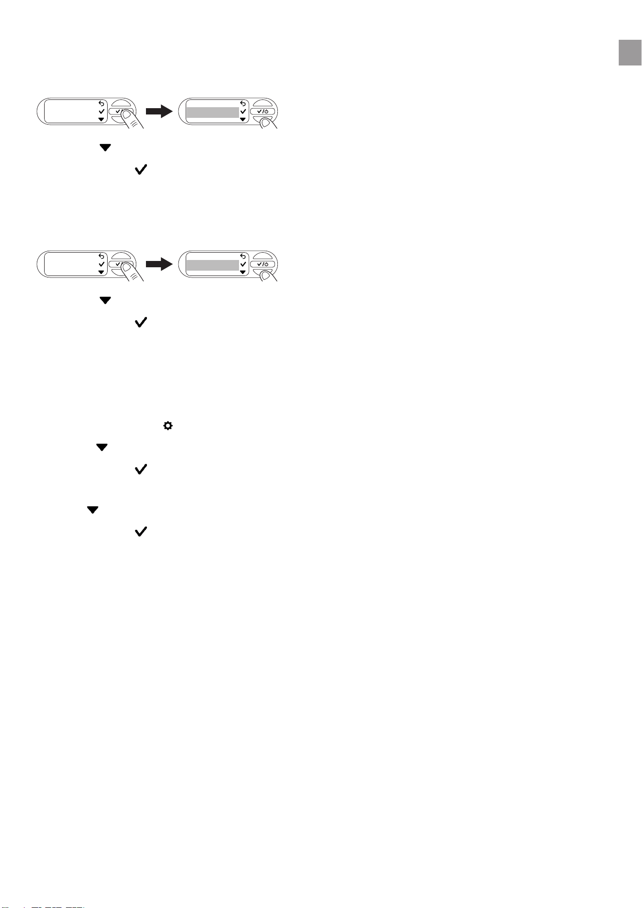
8.1 Timer
→ OpentheTimermenutostartorsetthetimer.
The timer is factory set to 15 minutes by default.
Timer 15 min
→ Starting the timer
→ Select to start the timer.
After a 3-second countdown has elapsed, the PTU switches on.
→ Youcancancelthecountdownbyselecting[img_cancel].
→ Stopping the timer
→ Select to stop the timer.
1. Setting the timer
2. Navigate to Set run time with .
3. Conrmwith to set the run time.
4. Select tosettherstdigitofthedesiredminutenumber.
5. Conrmwith to move to the next digit block.
6. Select to set the second digit of the desired minute number.
7. Conrmwith to save the timer value and start the timer.
After a 3-second countdown has elapsed, the PTU switches on.
8.2 Mode (adjustable pressure ranges)
→ OpentheModemenutoselectbetweenEco,NormalandIndividual.
Mode
ECO
MODE
8.2.1 Mode selection
1. Use tonavigatetothedesiredmode(see“5.2Adjustablepressureranges”).
Conrm with .
The screen displays “Saved”.
en
23
8.2.2 Individual mode
1. Use tonavigateto“Individual”
2. Conrmwith to select personalised pressure values for the cut-in and cut-out pressure.
1.8 bar
CUT-IN PRESSURE
Custom
MODE
3. Select the desired cut-in pressure with .
4. Conrmwith .
1.8 bar
CUT-IN PRESSURE
3.7 bar
CUT-OUT PRESSURE
5. Select the desired cut-out pressure with .
Conrm with .
The desired cut-in and cut-out pressure has been saved. The screen displays “Saved”. The PTU is
now operated in individual mode.
Note: Toensureoptimumoperation,thePTUpreventsthesettingofapressuredierencebetween
the cut-in and cut-out pressure of less than 1 bar.
8.3 Power Boost
1. Openthe“PowerBoost”menu.
Power Boost
ON
POWER BOOST
2. Use toswitchthefunctiononoro.
3. Conrmyourselectionwith .
The screen displays “Saved”.
en
24
8.4 Bluetooth
TousetheBluetoothfunction,youwillneedtheGARDENABluetooth®app(see“6.1Operatingthe
pressure tank unit via app”).
8.4.1 Switching Bluetooth on and o
1. Openthe“Bluetooth”menu.
Bluetooth
ON/OFF
2. Use toswitchthefunctiononoro.
3. Conrmyourselectionwith .
The screen displays “Saved”.
8.4.2 Pairing (connecting a mobile device for the rst time)
In pairing mode, your pressure tank unit is available for Bluetooth connection to a mobile device that is
not yet connected.After successful pairing, the Bluetooth® app automatically connects to your pres-
sure tank unit without having to pair it again.
1. OpentheGARDENABluetooth®apponyourmobiledevice.
2. OpentheBluetoothmenuandnavigateto“Pairing”with .
3. Conrmyourselectionwith .
Pairing
Pairing...
03:00
4. You now have 3 minutes to connect your mobile device.
5. Follow the instructions in the GARDENA Bluetooth® app.
Connection successful:Thescreenshows“Success”.
Connection failed:Thescreendisplays“Failed”.
6. Select to try pairing again.
7. Conrmyourselectionwith .
8.4.3 Deleting devices
Here you can remove all devices connected to the PTU from the Bluetooth® app.
1. OpentheGARDENABluetooth®apponyourmobiledevice.
2. OpentheBluetoothmenuanduse tonavigateto“Deletedevices”.
3. Conrmyourselectionwith .
Delete
devices
Delete all
4. Conrmwith to remove all devices from the Bluetooth® app.
Thescreenshows“Success”.
Note:
If you want to reconnect your mobile device after deleting it, an error message appears.
→ Remove the PTU from the Bluetooth® settings of your mobile device and try again.
en
25
8.5 Brightness
You can change the brightness of your screen between 1 and 5.
1. Openthe“Brightness”menu.
Brightness
5
2. Select to adjust the brightness.
3. Conrmwith to select the brightness.
The screen displays “Saved”.
8.6 Language
1. Openthe“Language”menu.
Language
deutsch
english
2. Select to navigate between languages.
3. Conrmwith to select a language.
The screen displays “Saved”.
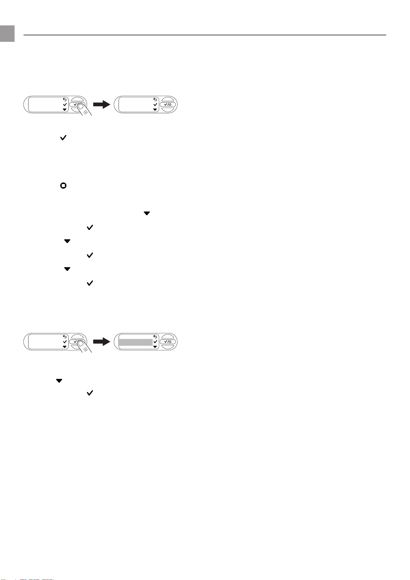
Tip: Incorrect language selected
If an incorrect language is selected, you can change this in the settings of your device within the GAR-
DENA Bluetooth® app or perform the following steps.
1. Openthesettings .
2. Press 5 times to navigate to the Language menu.
3. Conrmwith .
The screen shows the language selection.
4. Use to navigate to the desired language.
5. Conrmwith .
The screen displays “Saved”.
en
26
8.7 Reminder
1. Openthe“Reminder”menu.
No cleaning interval is set at the factory.
Remind me
OFF
CLEANING IN
2. Select to navigate between the times.
3. Conrmyourselectionwith .
The screen displays “Saved” and the cleaning interval begins.
Note: Help for setting an appropriate cleaning interval
→ VisuallycheckyourlterwhenyoureceivetheCleanltermessage.
→ Ifthelterisonlyslightlydirty,youcanincreasethemaintenanceinterval.
→ Ifthelterisheavilysoiled,cleanitandreducethemaintenanceinterval.
→ Ifthelterisfrequentlyheavilysoiled,usethe“Floatingsuction”accessoryorapumppre-lter.
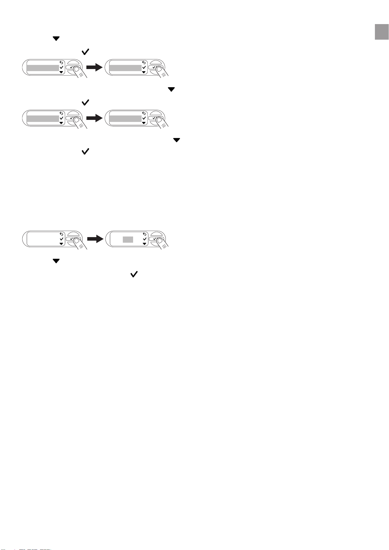
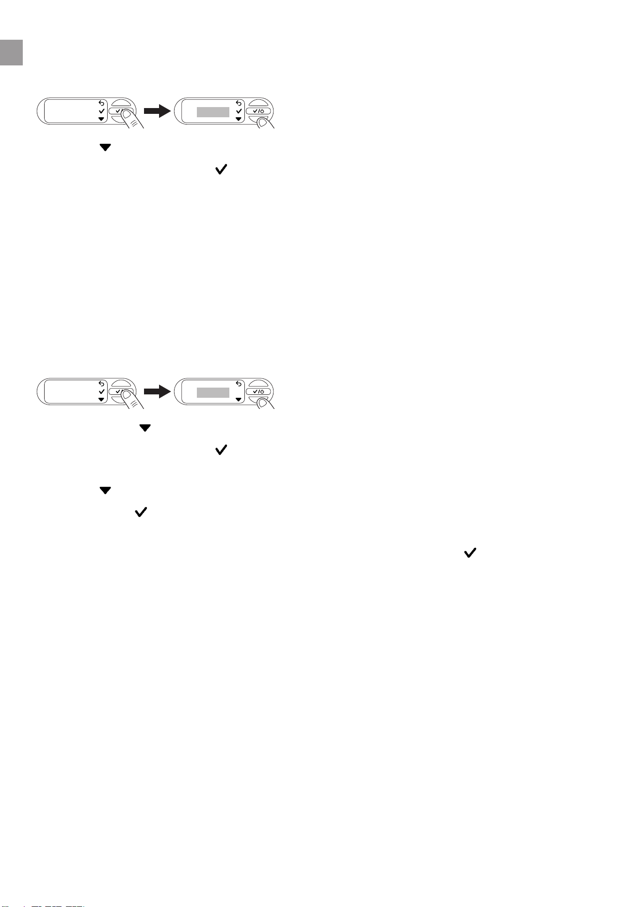
8.8 Direct start
If this function is switched on, the pump unit starts directly in automatic mode when the power is sup-
plied.
1. Openthe“Directstart”menu.
OFF
DIRECT START
Direct
Start
2. Navigate with to perform the desired setting.
3. Conrmyourselectionwith .
The screen displays “Warning”.
4. Select to read the next page of the warning.
5. Conrmwith when you reach the end of the warning.
The screen shows “Disconnect power”.
6. YoucannowdisconnectthepowersupplyfromthePTUorconrmwith to return to the menu.
8.9 Safety
ThismenudisplaysthefunctionsthatmonitortheowofthePTUand,intheeventofanerror,switch
othePTU.
en
27
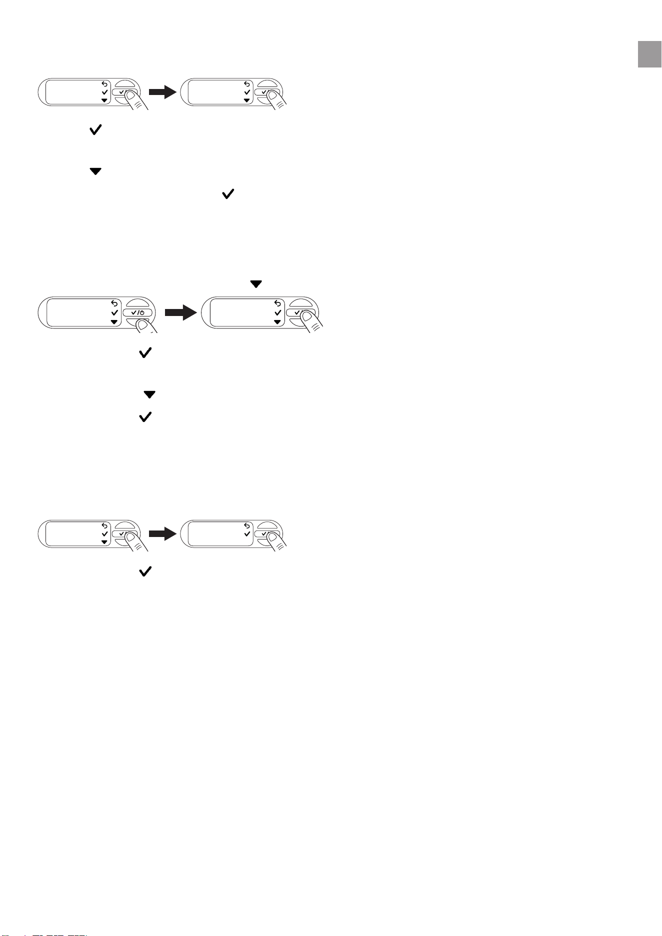
8.9.1 Leakage
1. Openthe“Safety”menu.
Safety
Leakage
2. Use toswitchtheLeakagefunctiononoro.
The screen shows OFF.
3. Use tonavigatebetween“OFF”and“ON”.
4. Conrmyourselectionwith .
Note: The function cannot provide guaranteed protection.
8.9.2 Max. run time
1. Openthe“Safety”menu.
2. Navigateto“Max.runtime”with .
Leckage
Max.
runtime
3. Conrmwith .
The current setting of your maximum run time opens.
4. Navigate with to perform the desired setting.
5. Conrmwith .
The screen displays “Saved”.
Note: The function cannot provide guaranteed protection.
8.10 Factory settings
1. Openthe“Factorysettings”menu.
Factory rese
Reset all se
2. Conrmwith to delete all settings you have made.
The screen shows “Success”.
en
28
9 MAINTENANCE
DANGER!
Risk of injury
Risk of injury due to unintentional startup.
→ Disconnect the plug from the mains socket.
→ Make sure that all parts have been properly secured after maintenance.
9.1 Cleaning the pressure tank unit [Fig. M1]
DANGER!
Risk of injury and damage to property!
Not cleaning the product properly can injure people and damage the product.
→ Do not use water or a water jet (especially a high-pressure water jet) to clean the product.
Do not use chemicals, including gasoline or solvents, to clean the product.
Some of these substances can destroy important plastic parts.
→ Clean the housing of the pressure tank unit with a damp cloth.
9.2 Flushing the pump unit
Thepumpunitmustbeushedafterithaspumpedchlorinatedwater.
1. Pumplukewarmwater(max.35°C),possiblywiththeadditionofamildcleaninguid(e.g.was-
hing-up liquid), until the pumped water is clear.
2. Disposeoftheresiduesasspeciedinlocalwastedisposalguidelines.
9.3 Checking the air pressure in the reservoir [Fig.M1]
Check the air pressure in the reservoir if the device starts to misbehave.
Theairpressureinthereservoirmustbe1.0bar.Anairpump/tyreinaterwithapressuregaugeis
required to top up the air. Excessive air pressure does not increase the water pressure and causes
malfunctions.
1. Unscrew the protective cap
11
.
2. Openanyshut-ovalvesinthedeliveryline(wateringaccessories,waterstopetc.).
3. This causes the pressure side to depressurise.
4. Attachtheairpump/tyreinatertothereservoirvalve
12
(car valve).
5. Topupwithairuntilthepressuregaugeontheairpump/tyreinatershows1.0bar.
6. Screw the protective cap
11
back into place.
en

29
9.4 Cleaning the lter [Fig.M2]
Dependingonthelevelofwaterpollution,theltershouldbecleanedatregularintervals,atthelatestif
it malfunctions.
1. Closealltheshut-ovalvesonthesuctionside.
2. Openanyshut-ovalvesinthedeliveryline(wateringaccessories,waterstopetc.).
3. This causes the pressure side to depressurise.
4. Unscrewthetting
8
onthellerneck
9
by hand (do not use any tools).
5. Pullthelter
13
verticallyoutofthellerneck
9
.
6. Hold the cup
14
tightandturnthelter
13
anticlockwise out of the cup
14
(bayonet lock).
7. Rinse the cup
14
under running water.
8. Usee.g.asoftbrushtocleanthelter
13
.
9. Reinstallthelter
13
in reverse order.
9.5 Cleaning the check valve [Fig.M3/M4]
1. Openthedirtcover
d
of the soil moisture sensor or unplug the connected soil moisture sensor.
2. Unscrew the 6 screws
15a
,
15b
and
15c
.
3. Pullothetwoshells
16
.
4. Unscrew the cap
18
anticlockwise using an Allen key (width 10).
5. Pull the check valve
19
out of the valve opening
v
.
6. Rinse the check valve
19
under running water.
7. Clean the valve opening
v
withadampcloth(withoutcleaninguid).
8. Reinstall the check valve
19
in reverse order.
9. Check the movement of the check valve
19
.
10. Reinstall the two shells
16
in reverse order.
11. Close the dirt cover
d
of the soil moisture sensor or plug the soil moisture sensor back in.
en

30
10 STORAGE
CAUTION!
Damage to the PTU due to frost
→ Store the PTU in a frost-proof place.
10.1 Decommissioning and storage [Fig.S1]
The product must be stored away from children.
1. Disconnect the plug from the mains socket.
2. Closeanyshut-ovalvesinthesuctionline.
3. Openanyshut-ovalvesinthedeliveryline(wateringaccessories,waterstopetc.).
4. This causes the pressure side to depressurise.
5. Unscrewthetting
8
onthellerneck
9
and the water drain plug
20
by hand.
6. This empties the PTU.
7. Tilt the PTU slightly towards the drain (up to 80°) so that the PTU drains fully.
8. Unscrew the suction hose and the pressure hose.
9. Screwthettingtight
8
onthellingopening
9
and the water drain plug
20
by hand (do not use
any tools).
10. Store the PTU in a dry, covered and frost-proof location.
en
31
11 TROUBLESHOOTING
DANGER!
Risk of injury
Risk of injury due to unintentional startup.
→ Disconnect the plug from the mains socket.
→ Allow the PTU to cool before troubleshoo-
ting.
11.1 Releasing the impeller [Fig.M3/T1]
If the impeller has been blocked by contamination (pump unit hums), it can be released.
1. Openthedirtcover
d
of the soil moisture sensor or unplug the connected soil moisture sensor.
2. Unscrew the 6 screws
15a
,
15b
and
15c
.
3. Pullothetwoshells
16
.
4. Pull the rubber plug
17
out of the service opening
21
.
5. Turn the impeller shaft
21
clockwiseusinganinsulatedat-bladescrewdriver.
This will release the blocked impeller.
6. Reinstall the rubber plug
17
and both shells
16
in reverse order. Make sure that the screws
15a
,
15b
and
15c
are assigned to the correct screw holes depending on their length.
7. Close the dirt cover
d
of the soil moisture sensor or plug the soil moisture sensor back in.
11.2 Error messages
Problem Possible cause Remedy
Very hot water
Very hot water
WARNING
The water in the PTU is signi-
cantlyheated.Waterleakage
and contact will result in injury.
→ Do not touch the stainless
steel housing of the PTU or
any escaping water.
→ Do not open any fastenings
or screw joints on the PTU
and the connected devices.
→ Let the PTU cool down.
→ Ensure that the water sup-
ply on the suction side is
present before restarting.
→ Fill the PTU completely with
water.
→ Openthepressure-side
consumer.
Frost
Frost
WARNING
There is an acute risk of frost
damage.
→ Decommission the PTU
immediately.
→ Store the PTU in a frost-
proof place.
Hardware error
Hardware error
WARNING
There is an error with the hard-
ware of the PTU.
→ Disconnect the PTU from
the power supply and con-
tact GARDENA Service.
en
32
Problem Possible cause Remedy
Error 0
WARNING
Error 0
The check valve is blocked or
not installed.
→ Check the check valve for
smooth movement and
contamination(see“9.5
Cleaning the check valve
[Fig.M3/M4]”).
→ Close the message with .
Max. run time reached
INFO
Max. runtime
Your pre-set run time limit has
been reached.
→ If necessary, adjust the
max.runtime(see“5.9.2
Maximum run time”). Close
the message with .
Leakage stop
WARNING
Leakage stop
A leak has been detected. → Check all hoses for leaks.
→ Replace any damaged
hoses if necessary. Contact
GARDENA Service for this.
→ Close the message with .
11.2.1 Messages related to errors 1, 2, 10 and 11
Message Remedy
Cooling
Error 1: Coo
WARNING | 4:59
If the respective error has been triggered 3 times within 30 minutes, the PTU starts a
5-minute cooling phase.
→ Let the PTU cool down and do not open it!
New attempt
Error 1:Try
2:59 h
→ Wait for the countdown to expire, or
1. Select to cancel the automatic restart.
2. Manually restart the PTU.
11.2.2 Errors 1 and 2
Error 1
WARNING
Error 2
WARNING
Problem Possible cause Remedy
Switch-o pressure cannot
be reached
The suction depth is too great
fortheselectedswitch-opres-
sure.
→ Selectalowerswitch-o
pressure.
PTU does not suction → Use a suction hose with
backowpreventer(see“13
Accessories/spareparts”)
orinstallabackowpreven-
ter on your suction line.
This can solve many suction
problems.
→ Fill the PTU and your sucti-
on hose or suction line with
water before starting.
en
33
Problem Possible cause Remedy
Malfunction on the suction side,
e.g. no water in the cistern,
water tank, water pipe etc.
→ Immerse the end of the
suction hose in water.
→ Eliminate the possible leaks
on the pressure side.
→ Clean the check valve on
the suction line and check
the installation direction.
→ Cleanthesuctionlterat
the end of the suction hose.
→ Cleanthesealofthelter
cover and fully tighten the
cover(see“9Maintenan-
ce”).
→ Cleanthelterinthepres-
sure tank unit.
The check valve is dirty. → Clean the check valve (see
“9.5Cleaningthecheck
valve[Fig.M3/M4]”).
The suction hose is deformed or
bent.
→ Use a new suction hose.
The consumer is closed or the
hose is kinked.
→ Opentheconsumer.
→ Stop the PTU by pressing
the middle key
b
.
→ Remove the kink from the
hose.
Thereisaleakinthettingon
thellerneck[Fig.A2].
→ Check the seal and replace
it if necessary. Tighten the
ttingbyhandwithoutusing
tools.
Air cannot escape because the
pressure hose is coiled up
1. Lay the pressure hose fully
out straight.
2. Route the hose upwards
from the pump outlet.
3. Do not kink the pressure
hose at the pump outlet.
4. Openallconsumersas
much as possible.
PTU does not start The housing has heated up and
the thermal circuit breaker has
been triggered.
→ Let the PTU cool down.
→ Release pressure by ope-
ningexistingshut-odevi-
ces in the pressure line.
The suction height is too
great for the selected
switch-o pressure
The suction height is too great
fortheselectedswitch-opres-
sure.
→ Decrease the suction height
orselectalowerswitch-o
pressure(see“8.2.2Indivi-
dual mode”).
11.2.3 Error 10 and 11
Error 10
WARNING
Error 11
WARNING
en

34
Problem Possible cause Remedy
Water ow interrupted Malfunction on the suction side,
e.g. no water in the cistern,
water tank, water pipe etc.
→ Immerse the end of the
suction hose in water.
→ Eliminate the possible leaks
on the pressure side.
→ Clean the check valve on
the suction line and check
the installation direction.
→ Cleanthesuctionlterat
the end of the suction hose.
→ Cleanthesealofthelter
cover and fully tighten the
cover(see“9Maintenan-
ce”).
→ Cleanthelterinthepres-
sure tank unit.
The check valve is dirty. → Clean the check valve (see
“9.5Cleaningthecheck
valve[Fig.M3/M4]”).
The suction hose is deformed or
bent.
→ Use a new suction hose.
The thermal circuit breaker has
been triggered (overheated
engine).
→ Let the PTU cool down.
Switch-o pressure cannot
be reached
The suction height is too great
fortheselectedswitch-opres-
sure.
→ Decrease the suction height
orselectalowerswitch-o
pressure(see“8.2.2Indivi-
dual mode”).
11.3 Error table for the PTU
Problem Possible cause Remedy
Pump unit does not start or
stops suddenly during ope-
ration
Thermal overload switch has
shut down the pump unit due to
overheating.
→ Let the pump unit cool
down, drain the PTU and
rellit.
→ Note the maximum media
temperature (35°C).
PTU is without power. → Check the fuses and electri-
cal connectors.
RCD switch has tripped (residual
current).
→ Remove the plug from the
mains socket and contact
GARDENA Service.
Cut-out pressure has been rea-
ched or the cut-in pressure has
not yet been reached.
→ No error: Automatic mode
Pump unit is running, but the
ow rate decreases sudden-
ly
Theintegrallterisclogged → Cleantheintegrallter.
The end of the suction hose is
notinwater[Fig.A5].
→ Immerse the suction hose
end deeper into the water.
en

35
Problem Possible cause Remedy
Suctionlterorbackowpre-
venter in the suction hose are
clogged.
→ Cleanthesuctionlteror
backowpreventer.
Suctionlineisleaking[Fig.A2]. → Rectify the leak.
Impeller is blocked (pump
hums).
→ Release the impeller.
Pressure hose is kinked. → Route the pressure hose
without kinking it and do
not bend the pressure hose
at the pump outlet.
The lid on the lling ope-
ning of the lter cannot be
unscrewed by hand
The thread is dirty. → To unscrew the component,
use multigrip pliers with a
cloth between the compo-
nent and the pliers.
→ Clean the thread on the lid
andonthelleropening.
Unusual switching behaviour
(suddenly dierent).
The pressure in the reservoir is
too low.
→ Relltheairinthereservoir
to 1 bar pressure.
Leakage on the pressure side. → Eliminate the leak on the
pressure side.
The reservoir membrane is
damaged.
→ Have the product checked
by GARDENA Service.
IMPORTANT!
Repairs may only be carried out by GARDENA service centres or by specialist dealers approved by
GARDENA.
→ Please contact your GARDENA service centre in the event of other faults (see reverse).
en

36
12 TECHNICAL DATA
Pressure tank unit Unit Value (Art. 9067) Value (Art. 9068)
Rated power W 900 1050
Mains voltage V (AC) 230 230
Mains frequency Hz 50 50
Max. delivery capa-
city
l/h 5600 6300
Max. pressure /Max.
delivery head
bar/m 4.7
47
4.9
49
Max. self-priming
level
m 8 8
Working pressure (cut-in to cut-out pressure)
ECO
Cut-in pressure
Cut-out pressure
bar
bar
1.5
2.6
1.5
2.6
Normal
Cut-in pressure
Cut-out pressure
bar
bar
1.8
3.3
1.8
3.3
Individual:
Cut-in pressure
Cut-out pressure
bar
bar
1.5–2.3
2.5–3.3
1.5–2.6
2.5–3.6
Permissible internal
pressure (pressure
side)
bar 6 6
Air pressure in tank bar 1.0 ± 0.1 1.0 ± 0.1
Power cable m 1.5 (H07RN-F) 1.5 (H07RN-F)
Weight without cable
(approx.)
kg 16.9 17.2
Sound pressure level
L
PA
Distance: 1m5 m10
m
dB
dB
dB
564236 584438
Sound power noise
level L
WA
1)
measured/guaran-
teed
Uncertainty k
WA
dB(A)
dB(A)
64/67
2.35
66/692.20
Max. media tempera-
ture
°C 35 35
Internal SRD (short-range radio antennas)
Frequency range
Maximum transmis-
sion power
Free-eld radio
range (approx.)
GHz
mW
m
2.402–2.480
10
10
2.402–2.480
10
10
Measurementmethodsaccordingto:1)Directive2000/14/EU
en

37
13 ACCESSORIES/SPARE PARTS
GARDENA suction hoses Kink- and vacuum-resistant, available either by the metre Art.
1720/1721(19mm(3/4")/25mm(1"))withoutconnectionttings
orinxedlengthsArt.1411/1418completewithconnectiont-
tings.
GARDENA suction hose con-
nector)
For connection on the suction
side.
Art. 1723/1724
GARDENA pump connection
set
For connection on the pressure
side.
Art. 1750/1752
GARDENA suction lter with
backow preventer
For installing in suction hoses
supplied by the metre.
Art. 1726/1727
/1728
GARDENA pump pre-lter Recommended for pumping
water that contains sand.
Art. 1730/1731
GARDENA fountain suction
hose
For vacuum-resistant connec-
tion of the PTU to tube wells or
rigid pipes. Length 0.5 m. With
33.3 mm (G 1) female thread on
both sides.
Art. 1729
GARDENA oating suction For dirt-free suction below the
water surface.
Art. 1417
GARDENA quick coupler For pressure side connection of
1"pressurehoses.
Art. 7109/7103
GARDENA soil moisture sen-
sor
For watering depending on soil
moisture.
Art. 1188/1867
GARDENA extension cable
(length: 10metres)
To extend the sensor cable up
toamaximumof105metres.
Art. 1868
en

38
14 WARRANTY/SERVICE
14.1 Product registration
Pleaseregisteryourproductatgardena.com/registration.
14.2 Service
Pleasendthecurrentcontactinformationofourserviceonthebackpageandonline:
• UnitedKingdom:https://www.gardena.com/uk/support/advice/contact/
• Australia:https://www.gardena.com/au/support/advice/contact/
• NewZealand:https://www.gardena.com/nz/support/advice/contact/
• SouthAfrica:https://www.gardena.com/za/support/contact/
en

39
15 DISPOSAL
15.1 Disposal of the pressure tank unit
(in accordance with Directive 2012/19/EU/S.I. 2013 No. 3113)
The product must not be disposed of together with normal household waste. It must be dis-
posed of in line with local environmental regulations.
IMPORTANT!
→ Dispose of the product through or via your local recycling collection centre.
en

40
16 ANNEX
16.1 Assignment of trademarks
The Bluetooth® word mark and logos are registered trademarks owned by Bluetooth® SIG, Inc. and
any use of such marks by GARDENA is under licence.
Apple and the Apple logo are trademarks of Apple Inc., registered in the United States and other
countries. App Store is a service mark of Apple Inc., registered in the United States and other count-
ries.
Google and the Google Play logo are trademarks of Google LLC.
Othertrademarksandtradenamesarethoseoftheirrespectiveowners.
16.2 EC Declaration of Conformity
GARDENAManufacturingGmbHherebycertiesthattheradioequipmenttype(Art.9067/9068)isin
compliancewithdirective2014/53/EU.
The full text of the EC declaration of conformity is available at the following Internet address:
http://www.gardena.com/int/support/safety-regulations.
en
41
17 PERFORMANCE CHARACTERISTICS
5300 SilentComfort, Art. 9067 6300 SilentComfort, Art. 9068
30 m
20 m
10 m
max.
47 m
40 mmax. 900 l/h
max. 2.200 l/h
max. 3.600 l/h
max. 4.500 l/h
max. 8 m
30 m
20 m
10 m
max.
49 m
40 mmax. 1.400 l/h
max. 3.000 l/h
max. 4.300 l/h
max. 5.700 l/h
max. 8 m
42
261 mm
190 mm
A6
de Bohrschablone

43
Industriezeile 36
4010 Linz
Phone: (+43) 732 77 01 01-485
service.gardena@husqvarnagroup.com
Cyprus
Pantelis Papadopoulos S.A.
92 Athinon Avenue
Athens
10442 Greece
Phone: (+30) 21 0519 3100
Czech Republic
Gardena
Service Center Vrbno
c/o Husqvarna
Manufacturing CZ s.r.o.
Jesenická 146
79326 Vrbno pod Pradedem
Phone: 800 100 425
Denmark
GARDENA DANMARK
Lejrvej 19, st.
3500 Værløse
Tlf.: (+45) 70 26 47 70
gardenadk@husqvarnagroup.com
www.gardena.com/dk
Dominican Republic
BOSQUESA, S.R.L
Carretera Santiago Licey
Km. 5 ½
Esquina Copal II.
Santiago De Los Caballeros
51000 Dominican Republic
Phone: (+1) 809-562-0476
Egypt
Universal Agencies Co
26, Abdel Hamid Lotfy St.
Giza
Phone: (+20) 3 761 57 57
Estonia
Husqvarna Eesti OÜ
Valdeku 132
EE-11216 Tallinn
Finland
Oy Husqvarna Ab
Juurakkotie 5 B 2
01510 Vantaa
www.gardena.
France
Husqvarna France
9/11 Allée des pierres mayettes
92635 Gennevilliers Cedex
France
http://www.gardena.com/fr
N° AZUR: 0 810 00 78 23
(Prix d’un appel local)
Georgia
Transporter LLC
#70, Beliashvili street
0159 Tbilisi, Georgia
Number: (+995) 322 14 71 71
info@transporter.com.ge
www.transporter.com.ge
Service Address and
Importer to Great Britain
Husqvarna UK Ltd
Preston Road
Ayclie Industrial Park
Newton Ayclie
County Durham
DL5 6UP
Phone: (+44) (0) 344 844 4558
info.gar[email protected]
Greece
Π.ΠΑΠΑΔΟΠΟΥΛΟΣ ΑΕΒΕ
Λεωφ. Αθηνών 92
Αθήνα
Τ.Κ.104 42
Ελλάδα
Τηλ. (+30) 210 5193 100
Hong Kong
Tung Tai Company
151-153 Hoi Bun Road
Kwun Tong, Kowloon
Hong Kong
Phone: (+852) 3583 1662
Hungary
Husqvarna Magyarország Kft.
Ezred u. 1 – 3
1044 Budapest
Phone: (+36) 1 251-4161
vevoszolgalat.husqvarna@husqvarnagroup.com
Iceland
BYKO ehf.
Skemmuvegi 2a
200 Kópavogur
Phone: (+354) 515 4000
byko@byko.is
MHG Verslun ehf
Víkurhvarf 8
203 Kópavogur
Phone: (+354) 544 4656
India
B K RAMAN AND CO
Plot No. 185, Industrial Area,
Phase-2, Ram Darbar
Chandigarh
160002 India
Phone: (+91) 98140 06530
raman@jaganhardware.com
Iraq
Alshiemal Alakhdar Company
Al-Faysalieah, Near Estate Bank
Mosul
Phone: (+964) 78 18 18 46 75
Ireland
Liey Distributors Ltd.
309 NW Business Park, Ballycoolen
15 Dublin
Phone: (+353) 1 824 2600
info@lieyd.com
Israel
HAGARIN LTD.
Deutschland / Germany
GARDENA Manufacturing GmbH
Central Service
Hans-Lorenser-Straße 40
D-89079 Ulm
Produktfragen:
(+49) 731 490-123
Reparaturen:
(+49) 731 490-290
www.gardena.com/de/kontakt
Albania
KRAFT SHPK
Autostrada Tirane-Durres
Km 7
1051 Tirane
Phone: (+355) 69 877 7821
Argentina
ROBERTO C. RUMBO S.R.L.
Predio Norlog
Lote 7
Benavidez. ZC: 1621
Buenos Aires
Phone: (+54) 11 5263-7862
Armenia
AES Systems LLC
Marshal Babajanyan Avenue 56/2
0022 Yerevan
Phone: (+374) 60 651 651
masisohanyan@icloud.com
Australia
Husqvarna Australia Pty. Ltd.
Locked Bag 5
Central Coast BC
NSW 2252
Phone: (+ 61) (0) 2 4352 7400
customer[email protected]
Austria / Österreich
Husqvarna Austria GmbH
Industriezeile 36
4010 Linz
Tel.: (+43) 732 77 01 01-485
www.gardena.com/at/service/beratung/kontakt/
Azerbaijan
Proqres Xüsusi Firması
Aliyar Aliyev 212, Baku, Azerbaijan
Sales: +994 70 326 07 14
Aftersales: +994 77 326 07 14
www.progress-garden.az
info@progress-garden.az
Bahrain
M.H. Al-Mahroos
BUILDING 208, BLOCK 356,
ROAD 328
Salhiya
Phone: +973 1740 8090
Belarus / Беларусь
ООО «Мастер Гарден»
220118, г. Минск,
улица Шаранговича, дом 7а
Тел. (+375) 17 257 00 33
mg@mastergarden.by
Belgium
Husqvarna Belgium nv
Gardena Division
Leuvensesteenweg 542
Planet II E
1930 Zaventem
België
Bosnia / Herzegovina
Silk Trade d.o.o.
Poslovna Zona Vila Br. 20
Phone: (+387) 61 165 593
Brazil
Nordtech Maquinas e Motores Ltd.
Avenida Juscelino Kubitschek
de Oliveira Curitiba
3003 Brazil
Phone: (+55) 41 3595-9600
www.nordtech.com.br
Bulgaria
AGROLAND България АД
бул. 8 Декември, № 13
Офис 5
1700 Студентски град
София
Тел.: (+359) 24 66 6910
info@agroland.eu
Canada / USA
GARDENA Canada Ltd.
125 Edgeware Road
Unit 15 A
Brampton L6Y 0P5
ON, Canada
Phone: (+1) 905 792 93 30
gardena.customerservice@husqvarnagroup.com
Chile
REPRESENTACIONES JCE S.A.
AV. DEL VALLE NORTE 857 PISO 4
HUECHURABA, SANTIAGO, CHILE
Phone: (+ 56) 2 2414 2600
China
办公室地址:
上海市长宁区金钟路788号荟聚办公楼D栋7楼
03-05单元
Oce Add:
Unit3-5, 7F, Livat Tower D, No.788, Jin Zhong Rd., Chang
Ning Dist., Shanghai, PRC 200335
Colombia
Equipos de Toyama Colombia SAS
Cra. 68 D No 25 B 86 Of. 618
Edicio Torre Central
Bogota
Phone: +57 (1) 703 95 20 /
+57 (1) 703 95 22
www.toyama.com.co
Costa Rica
Exim CIA Costa Rica
Calle 25A, B°. Montealegre
Zapote
San José
Costa Rica
Phone: (+506) 2221-5654 / (+506) 2221-5659
Croatia
Husqvarna Austria GmbH
09067-20.960.04/0724
© GARDENA Manufacturing GmbH
D-89079 Ulm
https://www.gardena.com
2 Nahal Harif St.
8122201 Yavne
Phone: (+972) 8-932-0400
Italy
Husqvarna Italia S.p.A.
Centro Direzionale Planum
Via del Lavoro 2, Scala B
22036 ERBA (CO)
Phone: (+39) (0) 31 4147700
[email protected]arna.com
Japan
Husqvarna Zenoah Co. Ltd. Japan
1-9 Minamidai, Kawagoe
350-1165 Saitama
Japan
gardena-jp@husqvarnagroup.com
Kazakhstan
ТОО “Ламэд”
Russian
Адрес: Казахстан, г. Алматы,
ул. Тажибаевой, 155/1
Тел.: (+7) (727) 355 64 00 /
(+7) (700) 355 64 00
Kazakh
Мекен-жайы: Қазақстан,
Алматы қ.,
көш. Тәжібаевой, 155/1
Тел.: (+7) (727) 355 64 00 /
(+7) (700) 355 64 00
Kuwait
Palms Agro Production Co
Al Rai- Fourth Ring Road – Block 56.
P.O Box: 1976 Safat
13020 Al-Rai
Phone: (+965) 24 73 07 45
info@palms-kw.com
Kyrgyzstan
OOsO Alye Maki
Av. Moladaya Guardia 83
720014 Bishkek
Phone: (+996) 312 322115
Latvia
Husqvarna Latvija SIA
Ulbrokas 19A
LV-1021 Rīga
Lebanon
Technomec
Safra Highway (Beirut – Tripoli) Center
622 Mezher Bldg.
P.O.Box 215
Jounieh
Phone: (+961) 9 853527 /
(+961) 3 855481
Lithuania
UAB Husqvarna Lietuva
Ateities pl. 77C
LT-52104 Kaunas
Luxembourg
Magasins Jules Neuberg
39, rue Jacques Stas
Luxembourg-Gasperich 2549
Case Postale No. 12
Luxembourg 2010
Phone: (+352) 40 14 01
Malaysia
Glomedic International Sdn Bhd
Jalan Ruang No. 30
Shah Alam, Selangor
40150 Malaysia
Phone: (+60) 3-7734 7997
Malta
I.V. Portelli & Sons Ltd.
85, 86, Triq San Pawl
Rabat - RBT 1240
Phone: (+356) 2145 4289
Mauritius
Espace Maison Ltée
La City Trianon, St Jean
Quatre Bornes
Phone: (+230) 460 85 85
Mexico
AFOSA
Av. Lopez Mateos Sur # 5019
Col. La Calma 45070
Zapopan, Jalisco, Mexico
Phone: (+52) 33 3818-3434
Moldova
Convel SRL
Republica Moldova,
mun. Chisinau,
sos. Muncesti 284
Phone: (+373) 22 857 126
www.convel.md
Mongolia
Soyolj Gardening Shop
Narnii Rd
Ulaanbaatar
14230 Mongolia
Phone: +976 7777 5080
soyolj@magicnet.mn
Morocco
Proekip
64 Rue de la Participation
Casablanca-Roches Noires
20303 Morocco
Phone: (+212) 661342107
Netherlands
Husqvarna Nederland B.V.
GARDENA Division
Postbus 50131
1305 AC ALMERE
Phone: (+31) 36 521 00 10
Neth. Antilles
Jonka Enterprises N.V.
Sta. Rosa Weg 196
P.O. Box 8200
Curaçao
Phone: (+599) 9 767 66 55
New Zealand
Husqvarna New Zealand Ltd.
PO Box 76-437
Manukau City 2241
Phone: (+64) (0) 9 9202410
North Macedonia
Sinpeks d.o.o.
Ul. Kravarski Pat Bb
7000 Bitola
Phone: (+389) 47 20 85 00
Norway
Husqvarna Norge AS
Gardena Division
Trøskenveien 36
1708 Sarpsborg
Northern Cyprus
Mediterranean Home & Garden
No 150 Alsancak, Karaoğlanoğlu
Caddesi Girne
Phone: (+90) 392 821 33 80
info@medgardener.com
Oman
General Development Services
PO 1475, PC - 111
Seeb
111 Oman
Phone: 96824582816
Paraguay
Agroeld SRL
AV. CHOFERES DEL CHACO
1449 C/25 DE MAYO
Asunción
Phone: (+595) 21 608 656
consultas@agroeld.com.py
Peru
Sierras y Herramientas Forestal SAC
Av. Las Gaviotas 833, Chorrillos
Lima
Phone: (+51) 1 2 52 02 52
www.siersac.com
Philippines
Royal Dragon Traders Inc
10 Linaw Street, Barangay
Saint Peter Quezon City
1114 Philippines
Phone: (+63) 2 7426893
aida.fernande[email protected]
Poland
Gardena Service Center Vrbno
c/o Husqvarna Manufacturing CZ
s.r.o. Jesenická 146
79326 Vrbno pod Pradedem
Czech Republic
Phone: (22) 336 78 90
Portugal
Husqvarna Portugal, SA
Lagoa - Albarraque
2635 - 595 Rio de Mouro
Phone: (+351) 21 922 85 30
Fax: (+351) 21 922 85 36
Romania
Madex International Srl
Soseaua Odaii 117 - 123,
RO 013603 Bucureşti, S1
Phone: (+40) 21 352 7603
Russia / Россия
ООО „Хускварна“
141400, Московская обл.,
г. Химки,
улица Ленинградская,
владение 39, стр.6
Бизнес Центр
„Химки Бизнес Парк“,
помещение ОВ02_04
http://www.gardena.ru
Saudi Arabia
SACO
Takhassusi Main Road P.O. Box:
86387 Riyadh 12863
40011 Saudi Arabia
Phone: (966) 11 482 8877
webmaster@saco-ksa.com
Al Futtaim Pioneer Trading
5147 Al Farooq Dist.
Riyadh 7991
Phone: (+971) 4 206 6700
Serbia
Domel d.o.o.
Slobodana Đurića 21
11000 Belgrade
Phone: (+381) 11 409 57 12
Singapore
Hy-Ray PRIVATE LIMITED
40 Jalan Pemimpin
#02-08 Tat Ann Building
Singapore 577185
Phone: (+65) 6253 2277
info@hyray.com.sg
Slovak Republic
Gardena
Service Center Vrbno
c/o Husqvarna
Manufacturing CZ s.r.o.
Jesenická 146
79326 Vrbno pod Pradedem
Phone: 0800 154044
Slovenia
Husqvarna Austria GmbH
Industriezeile 36
4010 Linz
Phone: (+43) 732 77 01 01-485
service.gardena@husqvarnagroup.com
South Africa
Husqvarna South Africa (Pty) Ltd
Lifestyle Business Park –
Ground Floor Block A Cnr
Beyers Naude Drive and Ysterhout
Road Randpark Ridge, Randburg
Phone: (+27) 10 015 5750
South Korea
Kyung Jin Trading Co., Ltd
8F Haengbok Building, 210,
Gangnam-Daero 137-891 Seoul
Phone: (+82) 2 574 6300
Spain
Husqvarna España S.A.
Calle de Rivas nº 10
28052 Madrid
Phone: (+34) 91 708 05 00
atencioncliente@gardena.es
Sri Lanka
Hunter & Company Ltd.
130 Front Street
Colombo
Phone: 94-11 232 81 71
Suriname
Deto Handelmaatschappij N.V.
Kernkampweg 72-74
P.O. Box: 12782
Paramaribo
Suriname
Phone: (+597) 43 80 50
info@deto.sr
Sweden
Husqvarna AB /
GARDENA Sverige
Drottninggatan 2
561 82 Huskvarna
Sverige
Phone: (+46) (0) 36-14 60 02
Switzerland / Schweiz
Husqvarna Schweiz AG
Consumer Products
Industriestrasse 10
5506 Mägenwil
Phone: (+ 41) (0) 62 887 37 90
Taiwan
Hong Ying Trading Co., Ltd.
No. 46 Wu-Kun-Wu Road
New Taipei City
Phone: (+886) (02) 2298 1486
Tajikistan
ARIERS JV LLC
39, Ayni Street, 734024
Dushanbe, Tajikistan
Thailand
Spica Co. Ltd
243/2 Onnuch Rd., Prawat
Bangkok
10250 Thailand
Phone: (+66) (0)2721 7373
Tunisia
Société du matériel agricole et maritime
Nouveau port de peche de Sfax Bp 33
Sfax 3065
Phone: (+216) 98 419047/
(+216) 74 497614
Türkiye
Dost Bahçe
Yunus Mah. Adil Sk. No:3
Kartal
Istanbul
34873 Türkiye
Phone: (+90) 216 389 39 39
Turkmenistan
I.E. Orazmuhammedov Nurmuhammet
80 Ataturk, BERKARAR Shopping Center,
Ground oor, A77b,
Ashgabat 744000
TURKMENISTAN
Phone: (+993) 12 468859
Mob: (+993) 62 222887
info@jayhyzmat.com /
bekgiye[email protected]
www.jayhyzmat.com
UAE
Al-Futtaim ACE Company
L.L.C Building, Al Rebat Street
Festival City, Dubai
7880 UAE
Phone: (+971) 4 206 6700
Ukraine / Україна
АТ «Альцест»
вул Петропавлівська 4
08130, Київська обл.
Києво-Святошинський р-н. с.
Петропавлівська Борщагівка Україна
Тел.: (+38) 0 800 503 000
Uruguay
FELI SA
Entre Ríos 1083
11800 Montevideo
Phone: (+598) 22 03 18 44
info@felisa.com.uy
Uzbekistan
AGROHOUSE MChJ
O’zbekiston, 111112
Toshkent viloyati
Toshkent tumani
Hasanboy QFY, THAY yoqasida
Phone: (+998)-93-5414141 /
(+998)-71-2096868
info@agro.house
www.agro.house
Vietnam
Vision Joint Stock Company
BT1-17, Khu biet thu –
Khu Đoan ngoai giao Nguyen Xuan Khoat
Xuan Đinh, Bac Tu Liem
Hanoi, Vietnam
Phone: (+8424)-38462833/34
Zimbabwe
Cutting Edge
159 Citroen Rd, Msasa
Harare
Phone: (+263) 8677 008685
sales@cuttingedge.co.zw