TRA-0401
29.1"x19.1"x25.2"
7.6"x2.9"/ Ø3"
9.7"x14.1"/ Ø5.6"
TRA-0401
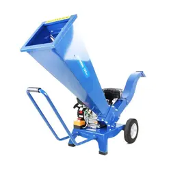
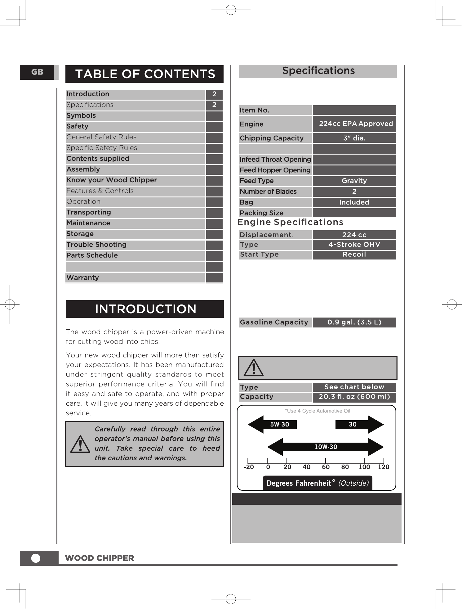
Chipper-shredder Specifications
Fuel Specifications
Use regular unleaded gasoline with a
minimum octane rating of 87 and an ethanol
content of less than 10% by volume. DO NOT
USE E15 or E85. DO NOT OVERFILL.
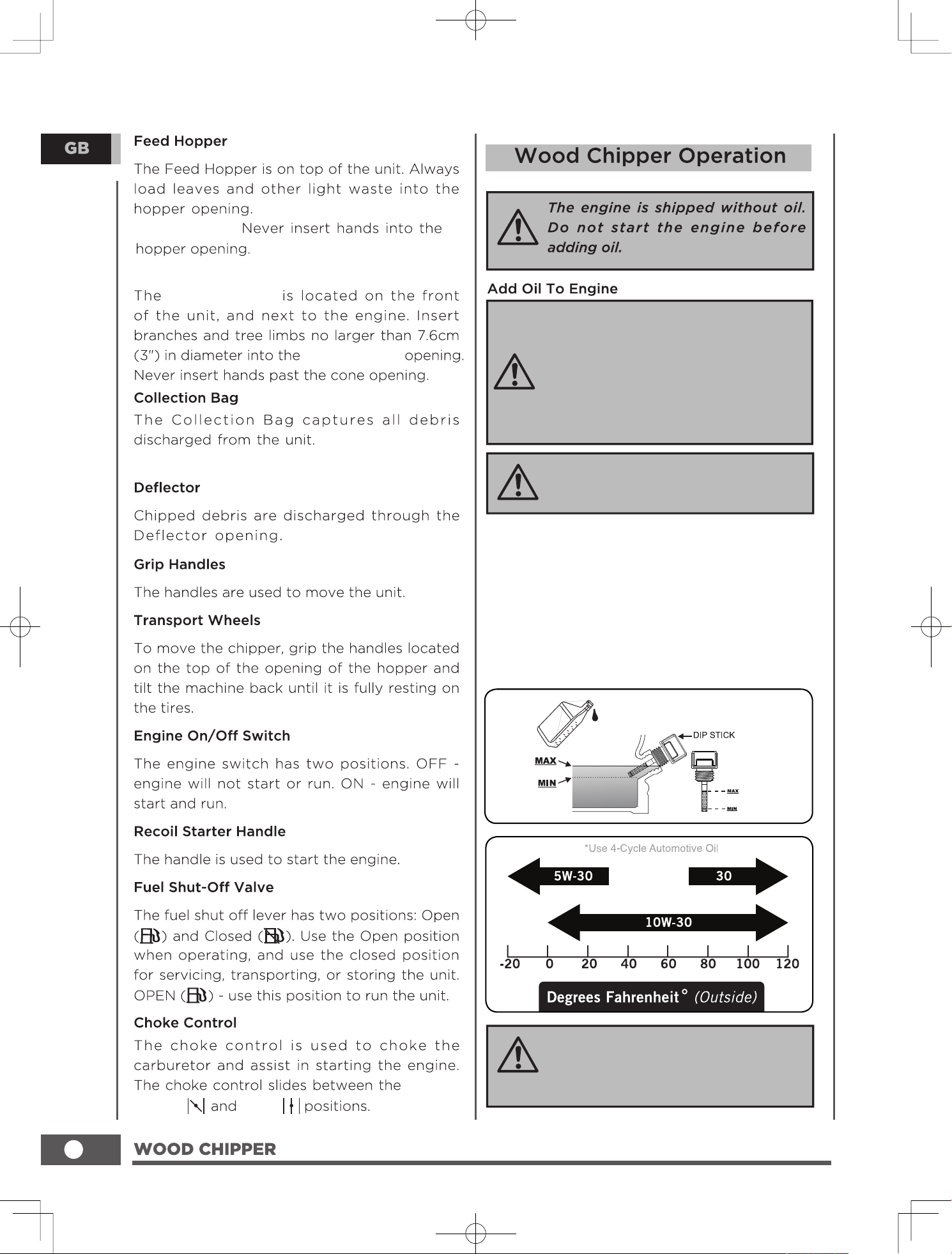
Engine Oil Specifications
DO NOT OVERFILL.
NOTICE
Weather will affect engine oil and engine
performance. Change the type of engine oil
used based on weather conditions to suit the
engine needs.
2
3
6
8
8
11
11
12
15
15
19
20
21
23
4
4
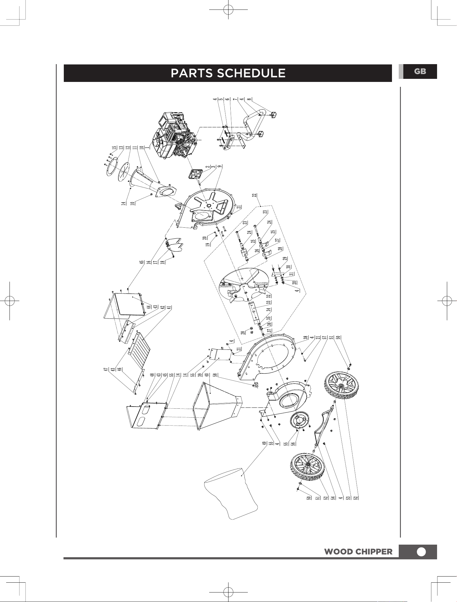
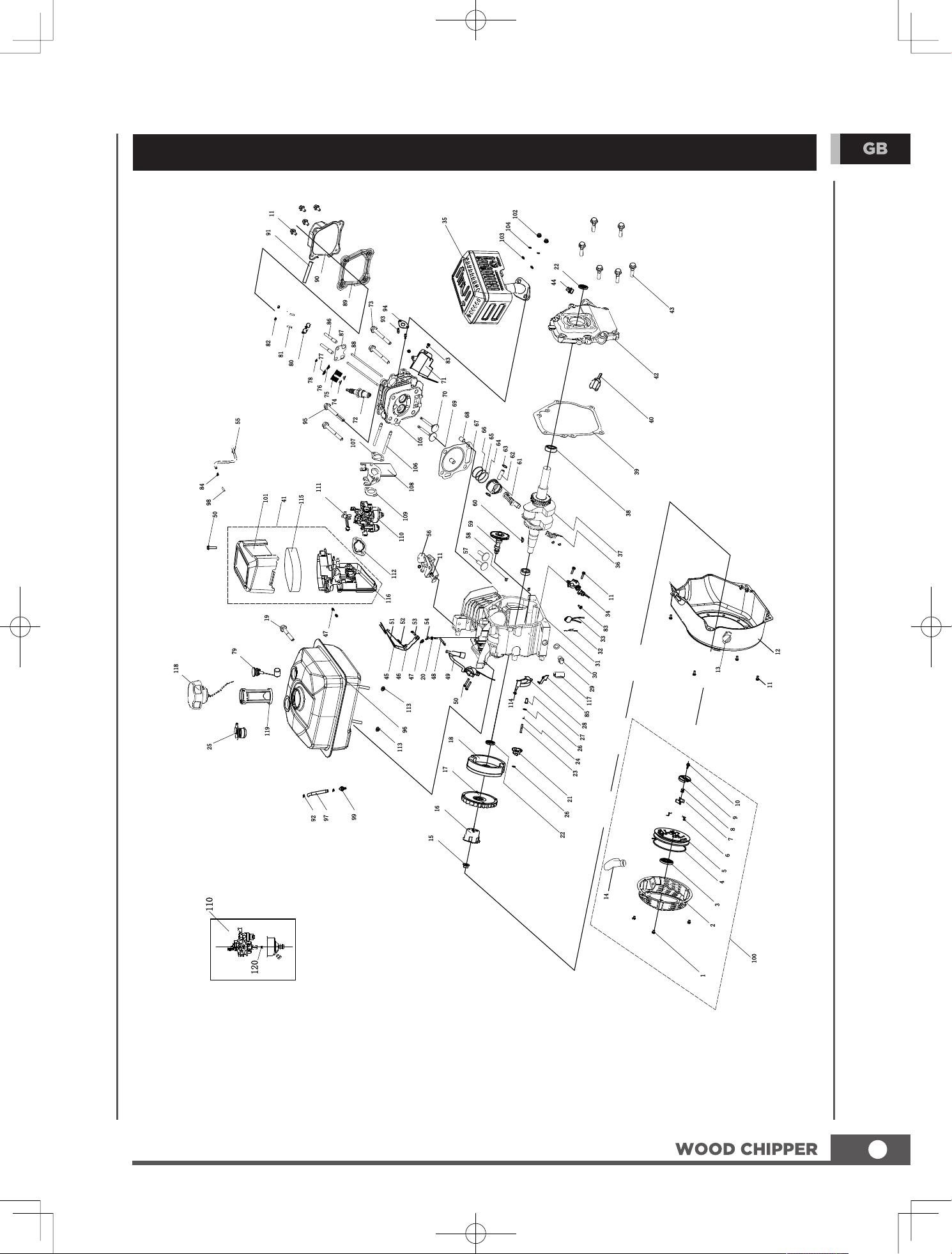
Engine Parts Schedule
26
Specifications, descriptions and
illustrations in this manual are as accurate
as known at the time of publication,but we
are always working to improve our
products. Therefore are subject to change
without notice.
Hooper Capacity 0.5"
The recommended oil type is 10W-30
automotive oil.
Important Message About
Temperature
Your product is designed and rated for
continuous operation at ambient
temperatures up to 104°F (40°C). When your
product is needed it may be operated at
temperatures ranging from 5°F (-15°C) to 122°
F (50°C) for short periods of time. In any
event, the product must always be operated
outdoors, in a well-ventilated area and away
from doors, windows and vents.
3
4
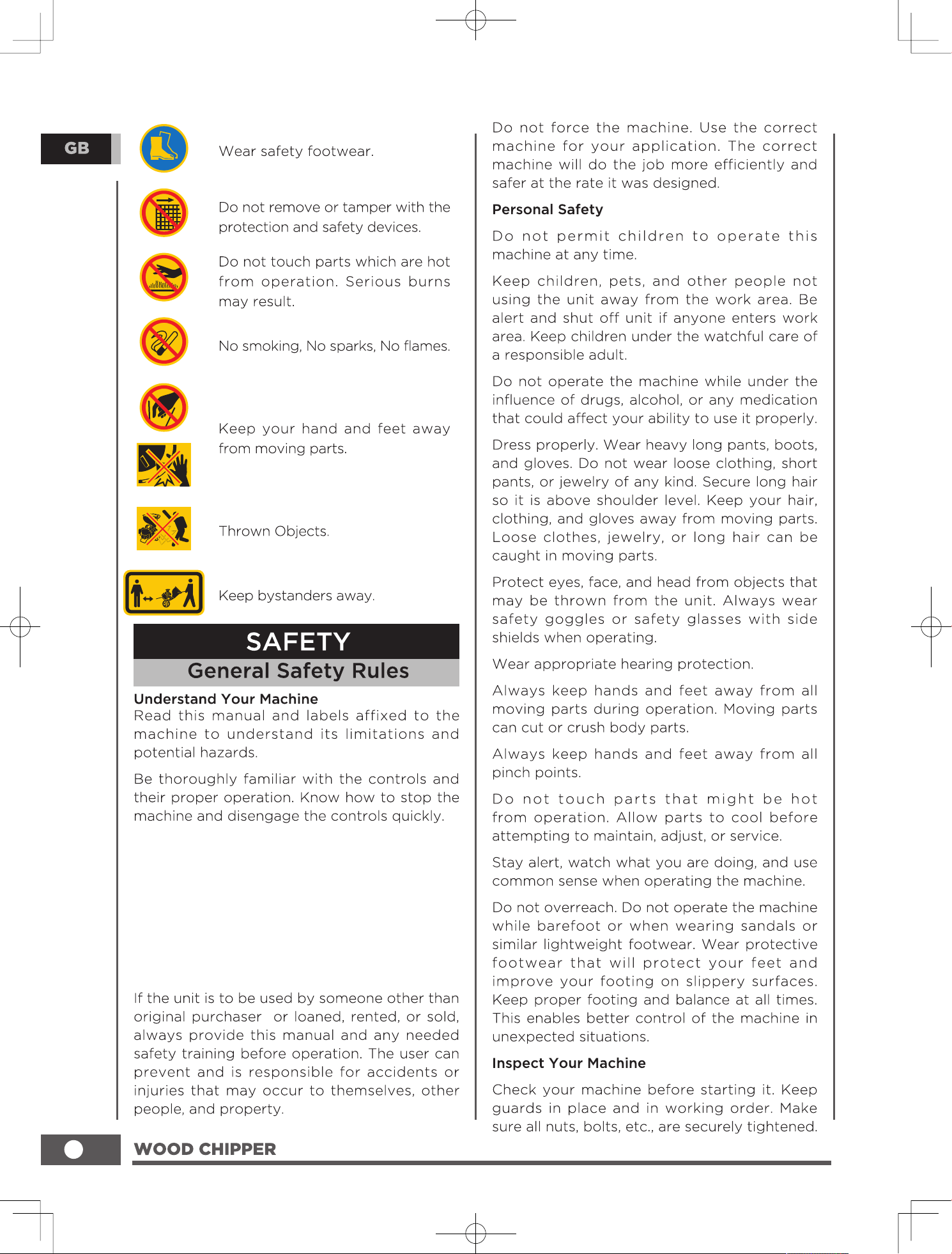
Make sure to read and understand all the
instructions and safety precautions as outlined
in the manual . Do not attempt to operate the
machine until you fully understand how to
properly operate and maintain the engine and
how to avoid accidental injuries and/or
property damage.
5
Never overfill the fuel tank. Fill the tank to no
more than 1cm below the bottom of the filler
neck to provide space for expansion as the
heat of the engine can cause fuel to expand.
6
Avoid feeding pine needles,flax and cabbage
tree leaves into the machine; these stringy
materials can wrap around the rotor shaft and
work their way into the bearing.
the machine to reach the highest spinning
revolutions before feeding the next load of
branches.
Allow time for
NOTE:Wet material is easy to block the
machine, so please do not put in.
7
1
2
3
4
5
6
7
11
8
9
10
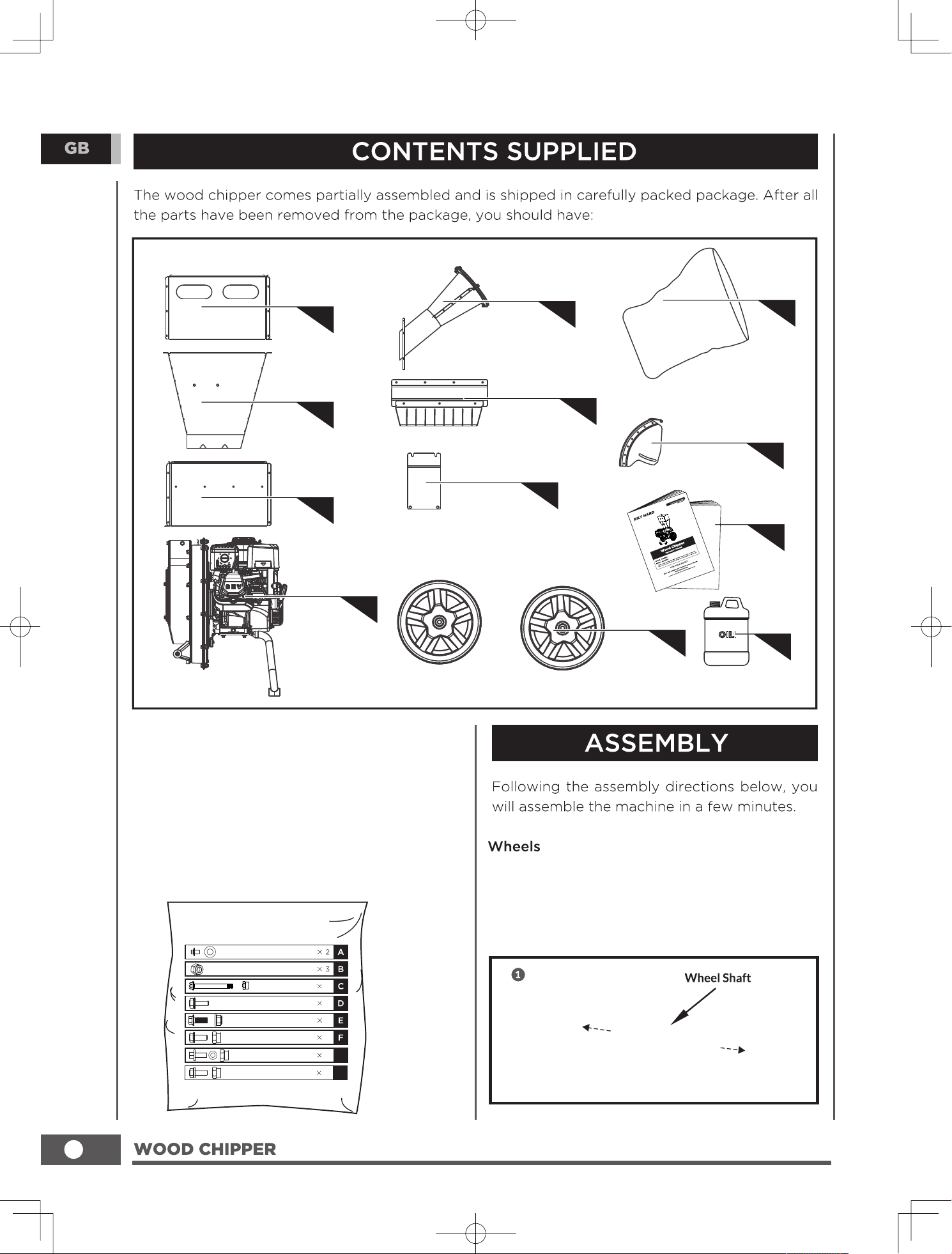
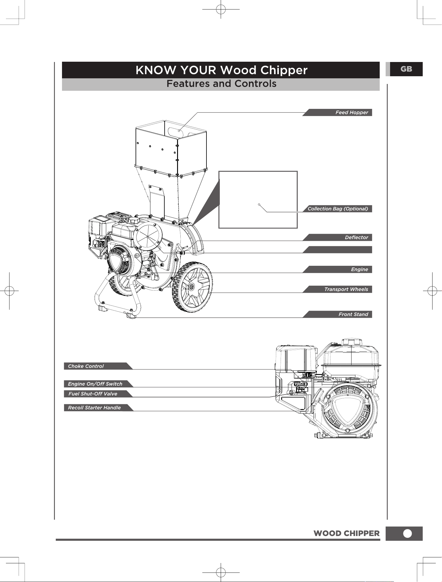
2.Hopper
1.Right Heightening Plate
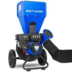
4.Engine
6.Baffle
8.Discharge Bag
10.Operator’s Manual
3.Left Heightening Plate
5.Chipper Chute
7.Support Plate
9.Discharge Port Cover
11.Wheels
M10
M6 X 55
1
M6 X 12
4
2
M5 X 12
10
G
12
H
M6 X 15
2
M6 X 15
8
M8 X 12
M8 X 20
1. Install the Wheel: Thread the 2 wheels on
the wheel shaft and screw the M8x12 bolt
and washer(A) into the wheel shaft end to
secure the wheels in place.
12.Oil 600ml ( )
TRA-0401
12
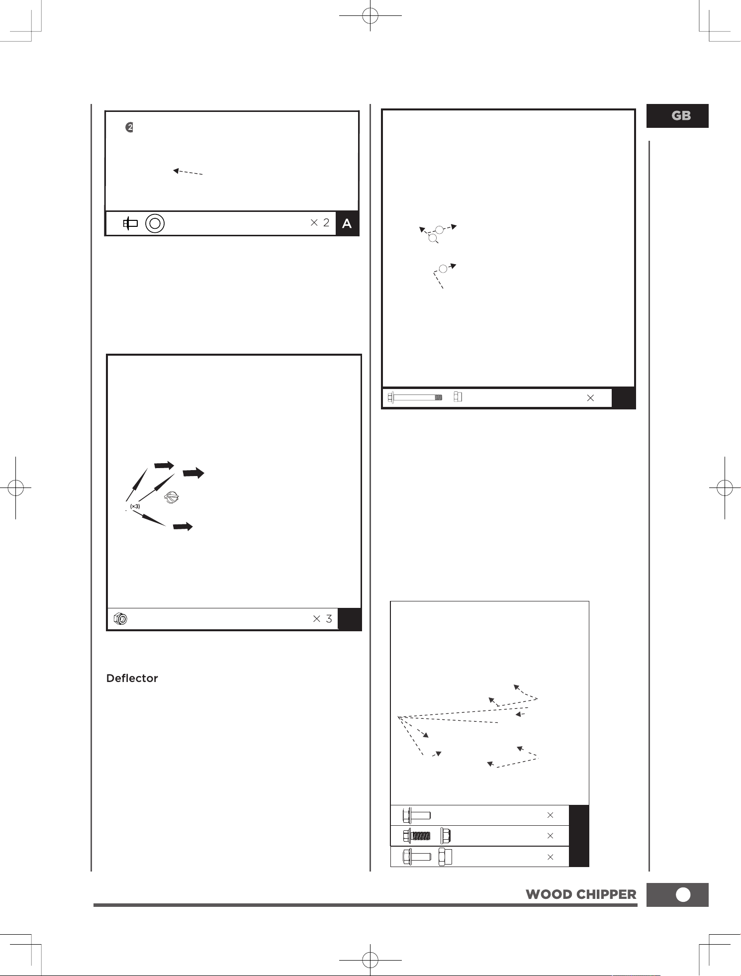
Install the Chipper Chute: Position the
chipper chute over the three threaded
studs protruding from the fixed plate, and
attach using three M10 nuts(B) nuts to
lock the chipper chute.
B
M6 X 55
1
C
Chipper Chute
Install the Discharging Cover: Insert the
M6x55 bolt(C) into the mounting hole of
the discharging cover, the shell and the
fixed plate, then use M6 nut to lock; Adjust
the discharge cover to the appropriate
height, and attach the knob to the
discharge cover, then use nut to lock the
discharging cover.
M6 X 12
M8 X 20
4
2
M6 X 15
2
D
E
F
9
M8 X 12
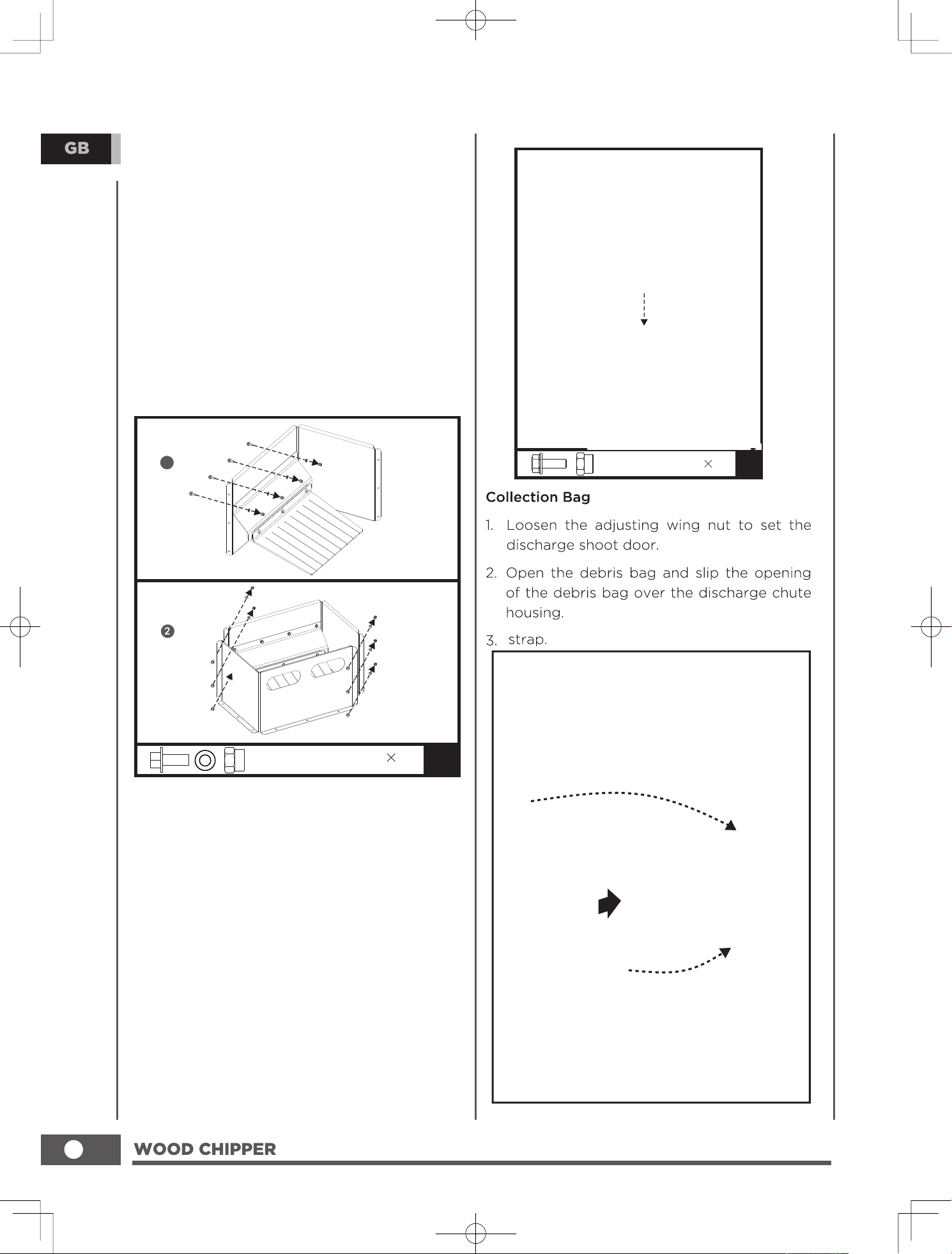
1. Install the Hopper: Put the hopper into the
lower cover and align with the mounting
hole, then secure the hopper with four M6x12
bolts(D)
2.Use two M8x20 bolts(E) to go through the
mounting hole of fixed plate and support
plate,then use M8 nuts to secure.
3.Insert two M6x15 bolts(F) into the
mounting holes of the hopper, then through
the mounting holes of the support plate, and
tighten them with two M6 nuts. Tighten M8
bolts and nuts of the fixed plate and support
plate; Tighten M6 bolts between the hopper
and thelower cover.
M10
M10
M6x55(x1)
2
3
1
M8x20
(x2)
M6x15
(x2)
M6x12
(x4)
Install the heightening plate: Put the
combination of heightening plates on the
upper hopper, as far as possible aligned with
the mounting hole; Thread twelve M6x15
bolts(H) through mounting holes on the
side of the heightening plate, and tighten
them with twelve M6 nuts; Finally tighten M5
bolts and nuts between the left and right
heightening plates.
M5 X 12
10
G
1
M6 X 15
12
H
strap and tighten the bag
10
1. Combine the left heightening plate and
baffle: align with mounting holes;Insert
four M5x12 bolts(G) into the mounting
hole from the outside of the left
heightening plate and tighten them with
four M5 nuts: Fix the baffle on the left
heightening plate.
2. Combine the right heightening plate
Align with screw holes of left and right
heightening plates,insert six M5x12 bolts(G)
into mounting holes from the front side of
the right heightening plate (the side with
the handle hole),and thread on the six M5
nuts,do not tight.
11
Chipper Chute
12
DO NOT attempt to crank or start
the engine before it has been
properly filled with the recommended
type and amount of oil. Damage to
the wood chipper as a result of
failure to follow these instructions
will void your warranty.
The recommended oil type is 10W-30
automotive oil.
1. Place the wood chipper on a flat, level
surface.
2.Remove oil fill cap/dipstick to add oil.
3.Add up to 20.3 fI.oz.(600ml) of
oil (not included) and replace oil fill
cap/dipstick. DO NOT OVERFILL.
4.Check engine oil level daily and add as
needed.
Check oil often during the break-in
period. Refer to the Maintenance
section for recommended service
intervals.
Chipper Chute
Chipper Chute
chipper chute
collection bag before operate the unit.
Secure the
START RUN
(BLUETYPE)
Material maximum diameter
0.5inch(1.3cm).
Note:Oil dipstick is blue color
13
The engine is equipped with a low oil
shut-o ffand will stop when the oil
level in the crankcase falls below the
threshold level.
1. Use clean, fresh, regular unleaded fuel with
a minimum octane rating of 87 and an
ethanol content of less than 10% by volume.
2. DO NOT mix oil with fuel.
3. Clean the area around the fuel cap.
4. Remove the fuel cap.
5. Slowly add the fuel in the tank. DO NOT fill
fully.Add fuel until reach the red line.
6.Screw on the fuel cap and wipe away any
spilled fuel.
Pouring fuel too fast through the
fuel screen may result in blow back
of fuel at the operator while filling.
Use regular unleaded gasoline with
a minimum octane rating of 87.
Do not mix oil and gasoline.
Add fuel until reach the red line.
DO NOT pump gas directly into the
wood chipper at the gas station. Use
an approved container to transfer the
fuel to the wood chipper.
DO NOT fill fuel tank indoors.
DO NOT fill fuel tank when the engine
is running or hot.
DO NOT overfill the fuel tank.
DO NOT light cigarettes or smoke
when filling the fuel tank.
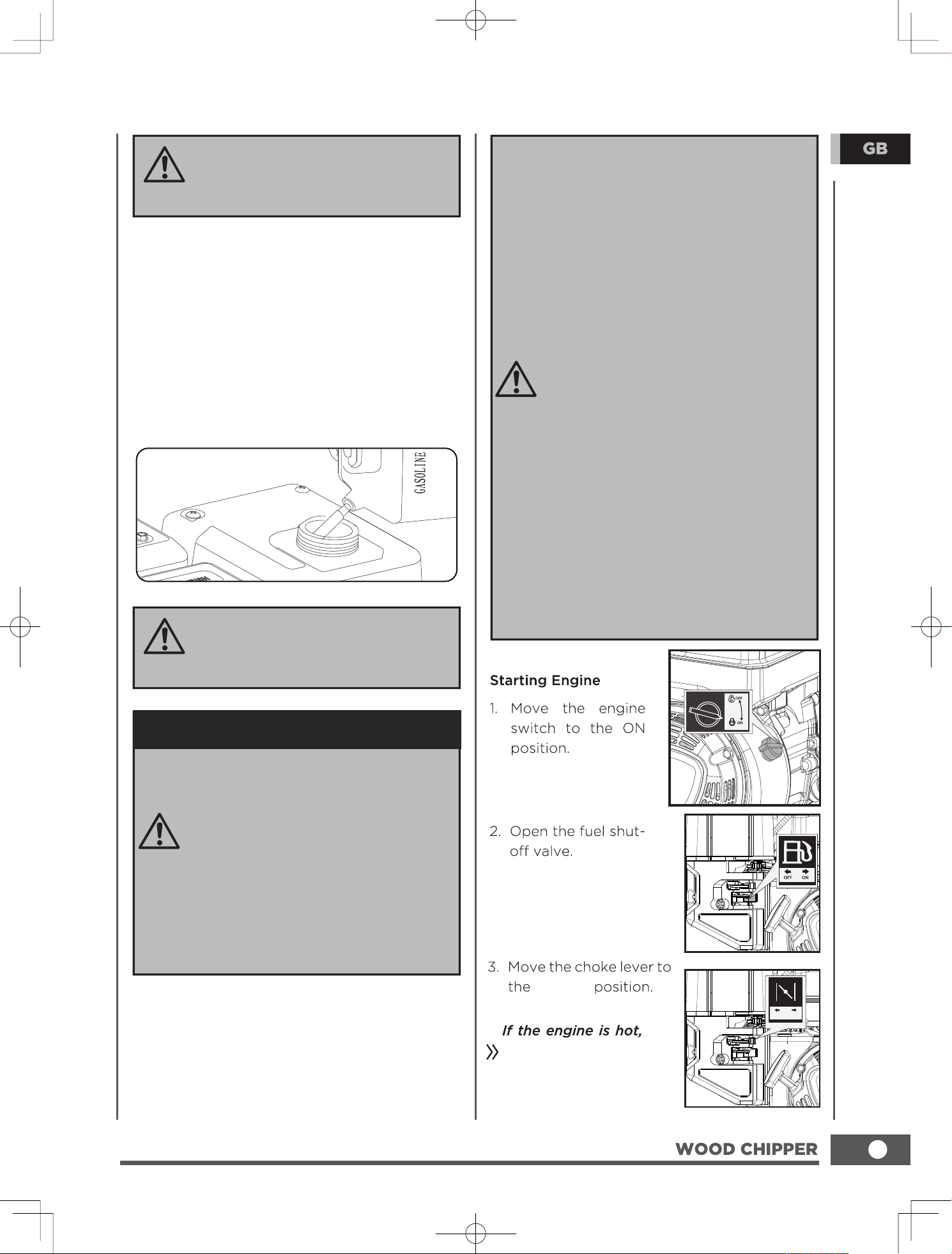
Add Gasoline To Engine
Our engines work well with 10% or less
ethanol blend fuels. When using blended
fuels there are some issues worth noting:
– Ethanol-gasoline blends can
absorb more water than gasoline
alone.
– These blends can eventually
separate, leaving water or a
watery goo in the tank, fuel
valve and carburetor.
– With gravity-fed fuel supplies,
this compromised fuel can be
drawn into the carburetor and
cause damage to the engine
and/or potential hazards.
– There are only a few suppliers of
fuel stabilizer that are formulated
to work with ethanol blend fuels.
– Any damages or hazards caused
by using improper fuel,improperly
stored fuel, and/or improperly
formulated stabilizers, are not
covered by manufacture’s warranty.
It is advisable to always shut o ffthe fuel
supply,run the engine to fuel starvation
and drain the tank when the equipment
is not in use for more than 30 days.
START
no need to flip the choke
lever onto START.
START RUN
14
Chute
0.5inch
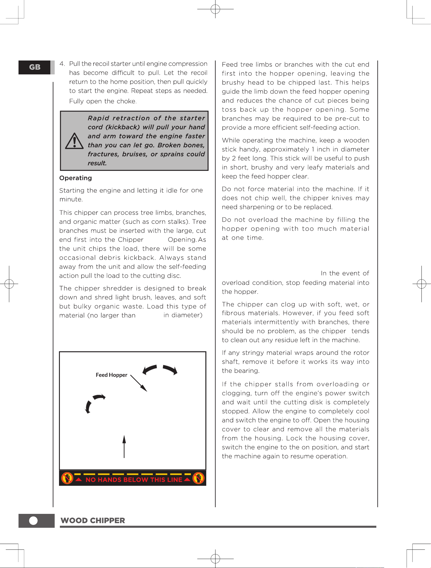
intothe top of the Feed Hopper. The material
is then pulled into the cutting chamber by
airflow
As a load passes through the
cutting disc and is discharged,the engine
speed may decrease. Allow enough time for
the engine to accelerate to the highest RPM
before another load is added.
Chipper Chute
5.
Place the spark plug wire back.
15
To shut down the machine,turn the
engine switch to the OFF position,
and it will gradually come to a
standstill.
CHOKE
Remove
the engine's spark plug.
Engine Maintenance
To prevent accidental starting, remove and
ground spark plug wire before performing
any service.
Changing the Engine Oil
Change oil when the engine is warm. Refer to
the oil specification
to select the proper grade for your operating
environment.
1. Remove the oil drain plug with a 15 mm
socket and extension. (Not included)
2. Allow the oil to drain completely.
3. Replace the drain plug.
4. Remove oil fill cap/dipstick to add oil.
5. Add up to 20.3 fl. oz (600 ml) of oil and
replace oil fill cap/dipstick. DO NOT
OVERFILL.
6. Dispose of used oil at an approved waste
management facility.
If using the dipstick to check oil level, DO
NOT screw in the dipstick while checking.
NOTICE
Used oil is a hazardous waste product and
must be disposed of properly. Do not discard
with household waste. Check with your local
authorities, service center, or dealer for safe
disposal/recycling facilities.
WARNING
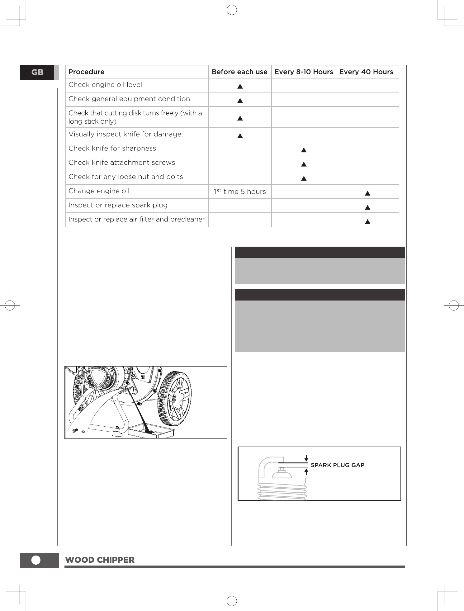
Cleaning and Adjusting the Spark Plug(s)
1. Remove the spark plug cable from the spark
plug.
2. Use a spark plug socket (not included) to
remove the plug.
3. Inspect the electrode on the plug. It must
be clean and not worn to produce the spark
required for ignition.
4. Make certain the spark plug gap is 0.7 - 0.8
mm(0.028 - 0.031 in.).
16
5. Refer to the spark plug section on the
Specifications page when replacing the
plug.
6. Carefully thread the plug into the engine.
7. Use a spark plug socket (not included) to
firmly install the plug.
8. Attach the spark plug wire to the plug.
Clean the Air Filter
1. Remove the plastic outer casing.
2. Remove the foam element.
3. Wash in liquid detergent and water.
Squeeze thoroughly dry in a clean cloth.
4. Saturate in clean engine oil.
5. Squeeze in a clean, absorbent cloth to
remove all excess oil.
6. Place the filter in the assembly.
7. Reattach the air filter cover.
17
chute
3
18
19
20
21
1
2
3
4
5
6
7
4
8
9
11
12
13
14
15
16
17
18
1 9
2 1
2 3
2 4
2 5
2 6
2 3
2 4
2 5
2 7
2 8
2 9
3 0
3 1
4
3 23 3
2 8
3 8
3 9
4 0
4 1
4 2
4 3
4 7
4 9
5 0
5 1
5 2
5 4
4
5 0
5 1
5 2
5 5
5 6
5 7
5 5
4
5 8
14
2 0
3 43 5
3 7
2 2
2 1
4
3 6
5 5
14
4 6
5 3
2 1
4
10
10
2 0
4 4
4 8
4 5
4 5
4 3
4 3
5 5
22
23
ENGINE PARTS SCHEDULE
1
2
3
4
5
6
7
8
9
10
11
12
14
22
26
21
23
24
26
27
28
29
30
33
34
11
36
37
38
39
40
42
43
15
16
17
18
96
119
112
110
109
108
106
105
50
49
48
20
47
46
45
51
52
53
54
50
57
59
58
60
61
62
63
64
65
66
67
68
70
44
22
71
83
89
90
91
88
87
86
93
74
75
76
78
80
81
82
72
31
114
111
102
56
11
73
94
11
19
107
77
47
69
92
97
99
85
113
113
35
100
25
41
115
83
55
95
84
98
117
101
116
79
110
120
104
103
32
13
118
24
Engine Parts List
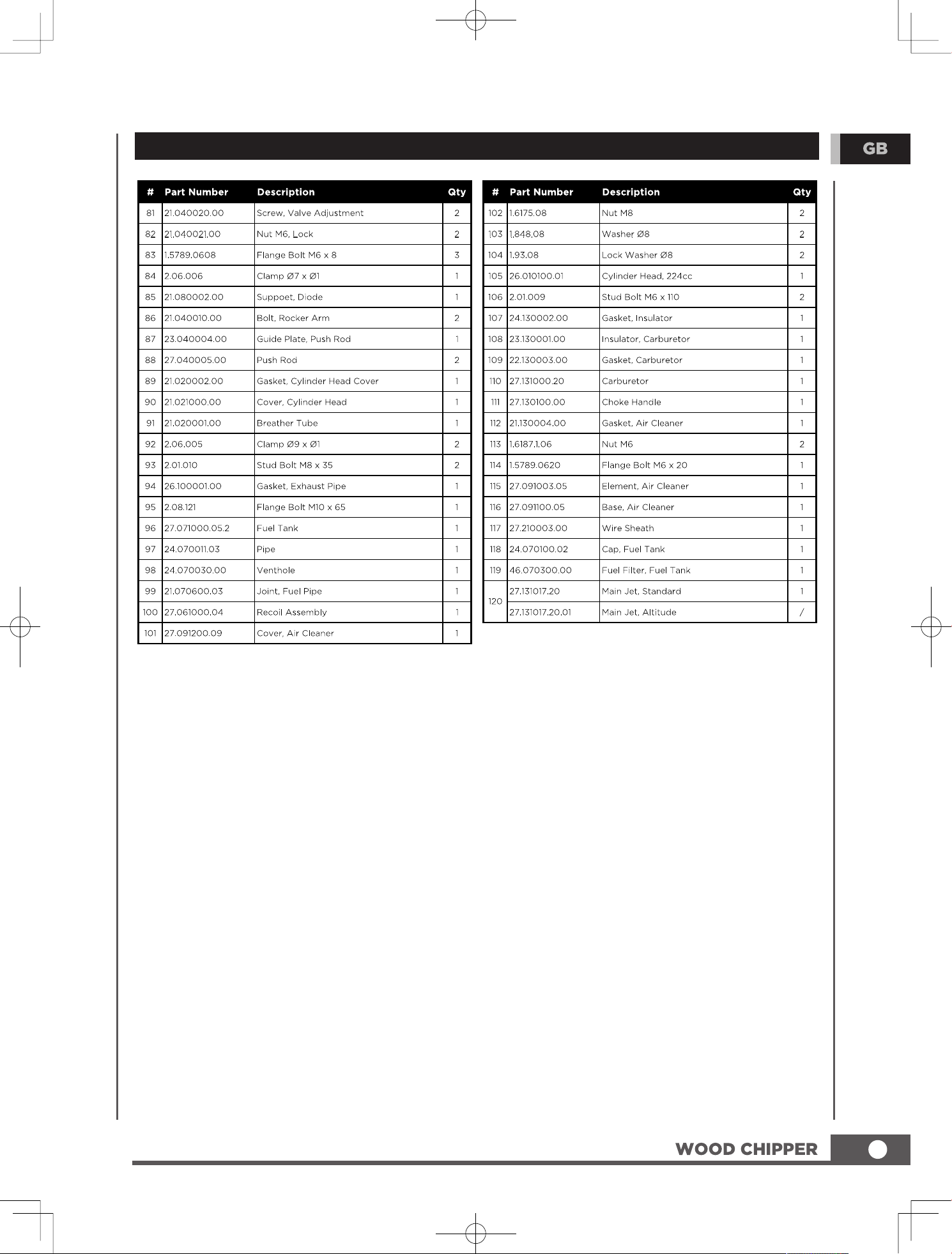
25
Engine Parts List
26
27
28
29