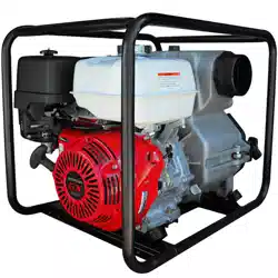

Operation Manual
To reduce the risk of injury, the user must read and understand the Operator’s
Manual before using this product. Save these instructions for future reference.
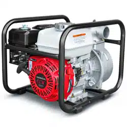
FULL TRASH
WATER PUMP
MODEL NUMBER: TW4H

2
TABLE OF CONTENTS
1. SAFETY INFORMATION
1.1 Laws Pertaining to Spark Arresters
1.2 Operating Safety
1.3 Safety While Using Combustion Engines
1.4 Service Safety
2. PRODUCT DETAILS
2.1 Product Diagram
2.2 Specifications
3. PRE-OPERATION CHECK
3.1 Check the Suction and Discharge Hoses
3.2 Check the Engine
4. OPERATION
4.1 Operating Controls
4.2. Check the Engine Oil Level
4.3 Motor Oil
4.4 Checking Oil
4.5 Priming the Pump
4.6 Check Engine Fuel
4.7 Check Fuel Level
5. START UP
6. CHANGING ENGINE OIL
7. MAINTENANCE
8. TROUBLESHOOTING
9. LIMITED WARRANTY
10. SERVICE CENTER
11. PARTS MANUAL
4
5
5
6
6
7
7
8
8
8
8
9
9
9
10
10
10
11
11
11
12
14
15
16
16
19

3
Register Your Equipment
Thank you for purchasing TOMAHAWK equipment! Your product is covered by the
TOMAHAWK Warranty policy, but in order to activate your warranty, we need you to register
your product. In addition to activating your equipment warranty, product registration will
grant you access to important product updates, streamlined customer service and more.
INCLUDED WITH YOUR REGISTRATION
☑ Equipment Warranty Activation
☑ Product Updates
☑ Streamlined Customer Service
☑ Excusive Discounts and Sales
STEPS TO REGISTER YOUR EQUIPMENT
1. Visit www.tomahawk-power.com
2. Choose “Product Registration” at the bottom of the page
3. Enter your equipment’s serial number to get started
4. Provide all required information
5. Submit Registration
Equipment Resources
Tomahawk Customer Service doesn’t stop at checkout. We understand to keep a job-site
running smoothly - the proper equipment, spare parts, instruction manuals, and more are
needed at the drop of a hat. Visit www.tomahawk-power.com to gain access to the incredible
resources below.
How To Video Library
More of a visual person? Visit our Video Library for equipment
assembly instructions, troubleshooting tips, and more!
Found on each product listing or the Service Videos Page
Manual and Assembly Guide Library
Visit our Manual Library if you are looking for a lost
operations manual or a particular spare part?
Found on each product listing or the Tomahawk Manuals Page
Service Requests
In need of a quick fix or a service center referral? Submit a
Service Request and a Tomahawk Technician will respond
shortly to get you the help you need.
Choose “Service Request” at the bottom of www.tomahawk-power.com

This manual provides information and procedures to safely operate and maintain this
equipment. For your own safety and protection from injury, carefully read, understand and
observe the safety instructions described in this manual.
Keep this manual or a copy of it with the equipment. If you lose this manual or need an
additional copy, please contact Tomahawk Power LLC or visit www.tomahawk-power.com
This equipment is built with user safety in mind; however, it can present hazards if
improperly operated and serviced. Follow operating instructions carefully. If you have
questions about operating or servicing this equipment, contact Tomahawk Power.
The information contained in this manual is based on equipment’s production at the time of
publication. Tomahawk Power reserves the right to change any portion of this information
without notice.
No part of this publication may be reproduced in any form or by any means, electronic or
mechanical, including photocopying, without express written permission from
Tomahawk Power.
Any type of reproduction or distribution not authorized by Tomahawk Power represents an
infringement of valid copyrights and will be prosecuted. We expressly reserve the right to
make technical modifications, even without due notice, which aim at improving our
machines or their safety standards.
1. SAFETY INFORMATION
This manual contains DANGER, WARNING, CAUTION, and NOTE callouts which must be
followed to reduce the possibility of personal injury, damage to the equipment, or
improper service.
This is the safety alert symbol. It is used to alert you to potential personal injury
hazards. Obey all safety messages that follow this symbol to avoid possible injury
or death.
DANGER indicates an imminently hazardous situation which, if not avoided, will
result in death or serious injury.
WARNING indicates a potentially hazardous situation which, if not avoided, could
result in death or serious injury.
CAUTION indicates a potentially hazardous situation which, if not avoided, may
result in minor or moderate injury.
DANGER
WARNING
CAUTION
4

5
CAUTION: Used without the safety alert symbol, CAUTION indicates a potentially
hazardous situation which, if not avoided, may result in property damage.
1.1 Laws Pertaining to Spark Arresters
Notice: State Health Safety Codes and Public Resources Codes specify that in certain
locations spark arresters be used on internal combustion engines that use hydrocarbon
fuels. A spark arrester is a device designed to prevent accidental discharge of sparks or
flames from the engine exhaust. Spark arresters are qualified and rated by the United
States Forest Service for this purpose.
In order to comply with local laws regarding spark arresters, consult the engine distributor
or the local Health and Safety Administrator.
1.2 Operating Safety
Familiarity and proper training are required for the safe operation of equipment!
Equipment operated improperly or by untrained personnel can be dangerous! Read
the operating instructions contained in both this manual and the engine manual and
familiarize yourself with the location and proper use of all controls. Inexperienced
operators should receive instruction from someone familiar with the equipment before
being allowed to operate the machine.
1.2.1 NEVER allow anyone to operate this equipment without proper training. People
operating this equipment must be familiar with the risks and hazards associated with it.
1.2.2 NEVER touch the engine or muler while the engine is on or immediately aer it has
been turned o. These areas get hot and may cause burns.
1.2.3 NEVER use accessories or attachments that are not recommended by Tomahawk
Power. Damage to equipment and injury to the user may result.
1.2.4 NEVER leave machine running unattended.
1.2.5 ALWAYS be sure operator is familiar with proper safety precautions and operation
techniques before using machine.
1.2.6 ALWAYS wear ANSI Z87.1-approved safety goggles or safety glasses with side shields,
or when needed, a face shield. Use a dust mask in dusty work conditions. Also use non-skid
safety shoes, hardhat, gloves, dust collection systems, and hearing protection when
appropriate. This applies to all persons in the work area.
1.2.7 ALWAYS close fuel valve on engines equipped with one when machine is not being
operated.
1.2.8 ALWAYS store equipment properly when it is not being used. Equipment should be
stored in a clean, dry location out of the reach of children.
WARNING

6
1.2.9 ALWAYS operate machine with all safety devices and guards in place and in working
order. DO NOT modify or remove safety devices. DO NOT operate machine if any safety
devices or guards are missing or inoperative.
1.2.10 ALWAYS read, understand, and follow procedures in Operator's Manual before
attempting to operate equipment.
1.3 Safety While Using Combustion Engines
Internal combustion engines present special hazards during operation and fueling!
Read and follow warning instructions in engine owner's manual and safety guidelines
below. Failure to follow warnings and DANGER safety guidelines could result in severe
injury or death.
1.3.1 DO NOT run machine indoors or in an enclosed area such as a deep trenches unless
there is adequate ventilation, through such items as exhaust fans or hoses are provided.
Gasoline exhaust from the engine contains poisonous carbon monoxide gas; exposure to
carbon monoxide can cause loss of consciousness and may lead to death.
1.3.2 DO NOT smoke while operating machine.
1.3.3 DO NOT smoke when refueling engine.
1.3.4 DO NOT refuel hot or running engine.
1.3.5 DO NOT refuel engine near open flame.
1.3.6 DO NOT spill fuel when refueling engine.
1.3.7 DO NOT run engine near open flames.
1.3.8 ALWAYS refill fuel tank in well-ventilated area.
1.3.9 ALWAYS replace fuel tank cap aer refueling.
1.3.10 ALWAYS check fuel lines and fuel tank for leaks and cracks before starting engine.
1.3.11 DO NOT run machine if fuel leaks are present or fuel lines are loose.
1.4 Service Safety
Poorly maintained equipment can become a safety hazard! In order for the
equipment to operate safely and properly over a long period of time, periodic
maintenance and occasional repairs are necessary.
1.4.1 DO NOT attempt to clean or service machine while it is running. Rotating parts can
cause severe injury.
1.4.2 DO NOT crank a flooded engine with the spark plug removed on gasoline-powered
engines. Fuel trapped in the cylinder will squirt out the spark plug opening.
DANGER
WARNING

7
1.4.3 DO NOT test for spark on gasoline-powered engines, if engine is flooded or the smell
of gasoline is present. A stray spark could ignite fumes.
1.4.4 DO NOT use gasoline or other types of fuels or flammable solvents to clean parts,
especially in enclosed areas. Fumes from fuels and solvents can become explosive.
1.4.5 ALWAYS keep area around muler free of debris such as leaves, paper, cartons, etc. A
hot muler could ignite them, starting a fire.
1.4.6 ALWAYS replace worn or damaged components with spare parts designed and
recommended by Tomahawk Power.
1.4.7 ALWAYS disconnect spark plug on machines equipped with gasoline engines, before
servicing, to avoid accidental start-up.
1.4.8 ALWAYS keep machine clean and labels legible. Replace all missing and hard-to-read
labels. Labels provide important operating instructions and warn of dangers and hazards.
1.4.9 ALWAYS check for damaged parts before each use. Carefully check that the
equipment will operate properly and perform its intended function. Replace damaged or
worn part s immediately. Never operate with a damaged part.
1.4.10 ALWAYS inspect the machine prior to placing in storage and before re-use. Store the
machine in a dry, secure place out of the reach of children when not in use.
1.4.11 ALWAYS use only accessories that are recommended by the manufacturer for use
with the machine. Accessories that may be suitable for one machine may create a risk of
injury when used with the machine.
2. PRODUCT DETAILS
2.1 Product Diagram

8
2.2 Specifications
3. PRE-OPERATION CHECK
3.1 Check the Suction and Discharge Hoses
3.1.1 Check the general condition of the hoses. Be sure the hoses are in serviceable
condition before connecting them to the pump. Remember that the suction hose must
be reinforced construction to prevent hose collapse.
3.1.2 Check that the sealing washer in the suction hose connector is in good condition.
3.1.3 Check that the hose connectors and clamps are securely installed.
3.1.4 Check that the strainer is in good condition and is installed on the suction hose.
NOTE: If there is air in the hose the hose the pump will not prime.
3.2 Check the Engine
3.2.1 Check the oil level. To avoid the inconvenience of an
unexpected shut-down by the Oil Alert system, always
check the engine oil level before startup.
3.2.2 Check the air filter. A dirty air filter will restrict air
flow to the carburetor, reducing engine and pump
performance. (Refer to Figure-2)
Model
TW4H
Outlet Diameter
4" X 4"
Max Total Head
91 ft
Suction Head
Engine Displacement
26 ft
389 cc
Max Discharge
580 gal/min
Engine Model
GX390
Engine Brand
Honda
Horsepower
13
Run Time
Pump Type
Self-priming
1.5 hrs
Fuel Tank Capacity
1.6 gal
Weight
148 lbs
Solid Capacity
2 in
Max PSI
36 PSI
Full-Trash Pump
Yes
FIGURE-2
9
4. OPERATION
4.1 Operating Controls
4.1.1 The centrifugal pump is operated using the engine operating controls. The engine
controls are located at the engine end of the pump frame.
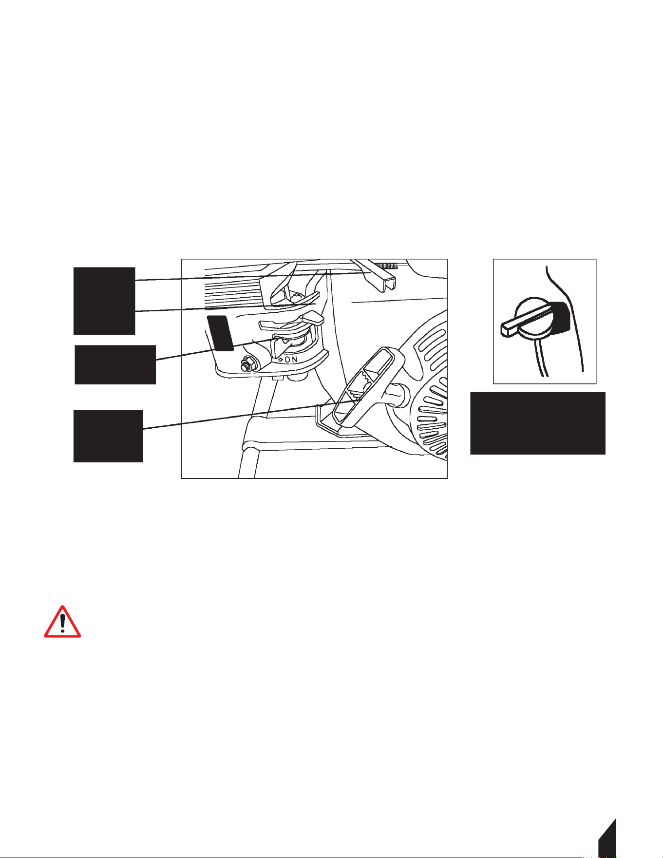
4.1.2 The controls consist of a throttle lever (for speed control), choke lever (for cold weather
starting), fuel shutoff lever (to prevent fuel spills), and a recoil starter (to turnover engine
by hand). (Refer to Figure-3.)
4.2. Check the Engine Oil Level
FIGURE-3
• ENGINE OIL IS A MAJOR FACTOR AFFECTING PERFORMANCE AND SERVICE LIFE.
NON-DETERGENT OILS AND 2-STROKE OILS ARE NOT RECOMMENDED BECAUSE
THEY HAVE INADEQUATE LUBRICATING CHARACTERISTICS
• CHECK THE OIL LEVEL WITH THE ENGINE ON A LEVEL SURFACE AND THE ENGINE
STOPPED.
WARNING

10
4.3 Motor Oil
Use Honda 4-stroke oil, or use an equivalent high detergent, premium quality motor oil
certified to meet or exceed U.S. automobile manufacturer’s requirements for Service
Classification SG, SF. Motor oils classified SG, SF will show this designation on the container.
SAE 10W/30 is recommended for general, all-temperature use. Other viscosity grades (see
Figure-4) may be used when the average temperature in your area is within the indicated
range.
4.4 Checking Oil
When checking oil, observe the following (refer to Figure-5):
4.4.1 Make sure the engine is in a level position.
4.4.2 Remove the oil filler cap/dipstick and wipe it clean.
4.4.3 Insert the filler cap/dipstick into the oil filler neck, but do not screw it in.
4.4.4 Remove the filler cap/dipstick and check the oil level.
4.4.5 If the level is low, fill to the top of the oil filler neck with the recommended oil.
4.4.6 Reinstall the oil filler cap/dipstick.
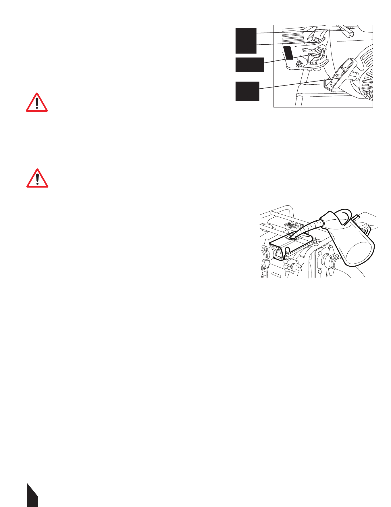
4.5 Priming the Pump
4.5.1 Before starting the water pump’s engine, remove priming plug from top of pump and
completely fill the chamber with water.
4.5.2 Reinstall the priming plug and tighten it securely.
FIGURE-4
FIGURE-5
OPERATING THE WATER PUMP DRY WILL DAMAGE THE PUMP’S SEAL. IF THE WATER
PUMP HAS BEEN OPERATED DRY, STOP THE ENGINE IMMEDIATELY AND ALLOW THE
MACHINE TO COOL BEFORE PRIMING THE PUMP USING THE STEPS ABOVE.
WARNING

11
4.6 Check Engine Fuel
4.7 Check Fuel Level
A. Remove cap from fuel tank. If fuel level is low, refill with unleaded automotive gasoline.
5. START UP
5.1 Pre-Start Checks
5.1.2 Check the following items before starting the engine.
5.1.3 Fuel leakage from fuel hose, sediment cup, etc.
5.1.4 Bolts and nuts for looseness. Components for damage or breakage.
5.1.5 Check centrifugal pump surroundings.
5.1.6 Keep centrifugal pump at least three (3) feet (one [1] meter) away from buildings
or other structures.
5.1.7 Only operate centrifugal pump in a dry, well-ventilated area.
5.1.8 Keep exhaust pipe clear of foreign objects.
5.1.9 Keep centrifugal pump away from open flame.
5.1.10 Keep centrifugal pump on a stable and level surface.
5.1.11 Do not block centrifugal pump air vents with paper or other material.
• MAKE SURE YOU REVIEW EACH WARNING IN ORDER TO PREVENT FIRE HAZARD.
• KEEP AREA CLEAR OF FLAMMABLES OR OTHER HAZARDOUS MATERIALS.
• MAKE SURE YOU REVIEW EACH WARNING IN ORDER TO PREVENT FIRE HAZARD.
• DO NOT REFILL TANK WHILE ENGINE IS RUNNING OR HOT.
• CLOSE FUEL SHUT OFF VALVE BEFORE REFUELING.
• BE CAREFUL NOT TO GET DUST, DIRT, WATER OR OTHER FOREIGN OBJECTS INTO
FUEL.
• WIPE OFF SPILLED FUEL THOROUGHLY BEFORE STARTING ENGINE.
• KEEP AWAY FROM OPEN FLAMES.
• DO NOT USE SMOKING MATERIALS WHEN FILLING THE FUEL TANK.
• DO NOT REFUEL WHILE SMOKING OR NEAR OPEN FLAME OR OTHER SUCH
POTENTIAL FIRE HAZARDS. OTHERWISE FIRE ACCIDENT MAY OCCUR.
• AVOID REPEATED OR PROLONGED CONTACT WITH SKIN OR BREATHING OF VAPOR.
• KEEP OUT OF REACH OF CHILDREN.
WARNING
WARNING
5.2 Starting and Operating the Engine
5.2.1 Refer to the Honda engine owner’s manual.
5.2.2 Put the fuel valve in the ON position.
5.2.3 Move the choke lever to the closed position.
(Figure- 6)
5.2.4 Set the ON/OFF switch to ON (the ON/OFF switch is mounted on the recoil shroud).
5.2.5 Move the throttle lever slightly to the le.
5.2.6 Pull the starter grip lightly until resistance is felt, then pull briskly.
5.2.7 As the engine warms up, gradually move the choke
lever to the OPEN position.
5.3 Using the Centrifugal Pump
5.3.1 Connect suction and discharge hoses. Make sure
suction hose is fitted with a strainer.
5.3.2 Remove priming plug from top of pump and fill
chamber with water.
5.3.3 Operate the engine at idle speed for 3 to 5 minutes.
5.3.4 Aer engine warm up, move the throttle lever to the operating speed.(Figure- 7)
5.4 Stopping the Centrifugal Pump
5.4.1 Move the throttle lever fully to the right.
5.4.2 Set the ON/OFF switch to OFF.
5.4.3 Turn the fuel valve to the OFF position.
6. CHANGING ENGINE OIL
6.1 Oil Alert
6.1.1 The oil alert sensor detects the lowering of the oil level in the crankcase and
automatically stops the engine when the oil level falls below the predetermined level.
6.1.2 When the engine stops automatically, check the oil level. Refill engine oil to the upper
level and restart the engine.
6.1.3 If the engine does not start by usual starting procedures, check the oil level.
12
FIGURE-7
FIGURE-6
The choke may not be needed if the engine is
warm or the air temperature is high.
WARNING
DO NOT allow the starter grip to snap back against the
engine. Return it gently to prevent damage to the starter.
WARNING

13
6.2 Changing Engine Oil
6.2.1 An initial oil change should be performed aer the first twenty- (20) hours of use.
Thereaer, change oil every 200 hours or as directed on the oil packaging.
6.2.2 Before changing the oil, check for a suitable way to dispose of the used oil. Do not pour
it down sewer drains, onto garden soil or into open streams. Refer to your local zoning and
environmental regulations for disposal and handling requirements.
6.2.3 Drain the oil while the engine is still warm to assure rapid and complete draining.
6.2.4 Remove the oil filler dipstick/cap and drain plug. Allow oil to drain from the engine
(refer to Figure-8).
6.2.5 Install the drain plug, and tighten it securely.
6.2.6 Refill with the recommended oil (refer to Figure 2-2).
6.2.7 Aer filling with oil, check the oil level.
6.2.8 When oil reaches the upper limit, install the oil filler dipstick/cap (Figure-9).
NOTE:
• Engine oil capacity:
1.09 liters (1.16 U.S. Quart)
FIGURE-8
FIGURE-9 FIGURE-10

14
7. MAINTENANCE
To maintain the centrifugal pump in peak operating condition, observe and implement the
maintenance and adjustment schedule in the table below. Inspect and/or service the
centrifugal pump at the intervals shown below.
Check the fuel and oil levels
Overhaul engine
Change fuel lines
Check and tighten the external
hardware
Wash cleaner element
Check spark plug and clean if
necessary
Change engine oil
Adjust spark plug gap
Clean and adjust carburetor, valve
clearance, and valve seat
along with cylinder head
Check rotor and stator
Replace engine isolation
mounts
Replace spark plug and cleaner
element
Clean fuel strainer
DAILY
BEFORE
STARTING
AFTER
FIRST 50
HOURS OR 3
MONTHS
AFTER
FIRST 200
HOURS OR 8
MONTHS
AFTER
FIRST 500
HOURS OR
EVERY YEAR
AFTER
FIRST 1000
HOURS OR
EVERY
2 YEARS

15
8. TROUBLESHOOTING
The troubleshooting tables below can be used as a guide to isolate centrifugal pump faults.
Refer to these tables when the engine fails to start aer several attempts. If, aer following
these procedures, the pump fails to start, contact the nearest Tomahawk pump dealer.
Fault Probable Cause Solution
Pump does not pump.
Insufficient priming water
Mechanical seal chipped or broken
Check valve damaged
Suction hose damaged or strainer clogged
Air leaks caused by O-ring damage
Add more water through priming plug
Replace mechanical seal
Replace check valve
Replace hose. Clean strainer
Replace O-rings
Discharge flow or pump
pressure too low.
Air leaks caused by O-ring damage
Suction hose or strainer clogged
Excessive impeller
clearance
Engine RPM too low
Lift head too high
Replace O-rings
Replace hose. Clean strainer
Disassemble to obtain casing cover and
impeller. Determine clearance and reshim
as required (refer to Replacement of
Mechanical Seal)
Check RPM and reset throttle as required
Lower lift head
Pump primes too
slowly.
Insufficient priming water
Mechanical seal chipped or broken
Check valve damaged
Suction hos
e damaged or
strainer clogged
Air leaks caused by O-ring damage
Engine RPM too low
Lift head too high
Add more water through priming plug
Replace mechanical seal
Replace check valve
Clean strainer.
Replace hose
Check RPM and reset throttle as required
Lower lift head
Noise or vibration Faulty mounting
Pump/engine attaching parts loose.
Tighten as required.
Damaged vibration isolation mounts.
Replace mounts.

9. EQUIPMENT WARRANTY
Your new TOMAHAWK® equipment is warranted to the original purchaser for a period of
one-year (12 months) from the original date of purchase. The TOMAHAWK® warranty is
against defects in design, materials and workmanship.
The following are not covered under the warranty:
9.1.1 Damage caused by abuse, misuse, dropping or other similar damage caused by or as a
result of failure to follow assembly, operation or user maintenance instructions.
9.1.2 Alterations, additions or repairs carried out by persons other than TOMAHAWK® or
their recognized agents.
9.1.3 Transportation or shipment costs to and from TOMAHAWK® or their recognized
agents, for repair or assessment against a warranty claim, on any machine.
9.1.4 Materials and/or labor costs to renew, repair or replace components due to fair
wear and tear.
9.1.5 TOMAHAWK® and/or their recognized agents, directors, employees or insurers will not
be held liable for consequential or other damages, losses or expenses in connection with or
by reason of or the inability to use the machine for any purpose.
Warranty Claims
Before submitting any warranty claim, you will need to register
your new TOMAHAWK® equipment through
www.tomahawk-power.com.
Follow the steps on page 3 or scan this QR codes to complete
the equipment registration. Aer registration is complete,
all warranty claims should firstly be directed to TOMAHAWK®
through the online Service Request form found
at www.tomahawk-power.com/pages/service-request.
10. SERVICES CENTERS
Our service centers are equipped to handle your equipment maintenance and repair needs
efficiently. With a network of authorized local service locations , you can find expert
support and genuine parts needed to keep your equipment running smoothly. All locations
are listed on the webpage https://tomahawk-power.com/pages/find-a-service-center.
16

17
Item #: TBS500
1.6HP SKID SPRAYER
+ 100FT HOSE & REEL
www.tomahawk-power.com
TRUSTED
NATIONWIDE
Powered by the industry’s most reliable
Honda GX35 engine, maintain constant,
adjustable pressure from 50 - 500 PSI with a
high flow rate of 2.8GPM to help you cover
more area so you can finish jobs faster!

1718
Item #: TG9000i
10,500W INVERTER
GENERATOR
www.tomahawk-power.com
BIG POWER
ANYWHERE
YOU NEED IT
Tomahawk TG9000i Inverter Generators are the
ultimate power solution for professionals who
demand top performance. Built with American grit,
this generator delivers a massive 10,500 Watts,
providing reliable, clean power for both sensitive
electronics and heavy-duty equipment.

19
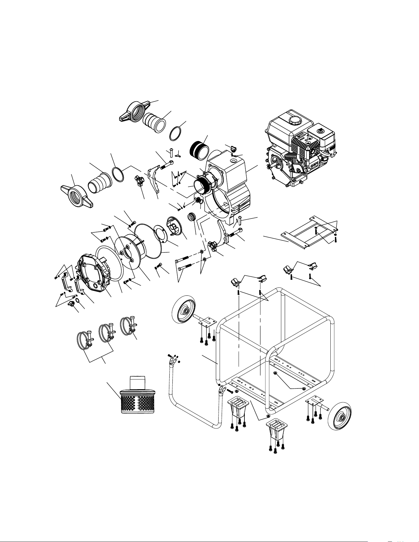
Parts Manual
FULL TRASH
WATER PUMP
MODEL NUMBER: TW4H
17
TW4H FULL TRASH PUMP
12
11
18
1
10
18
10
10
6
7
3
8
9
11
5
4
2
19
15
16
17
15
19
16
17
11
28
28
33
30
23
33
30
23
27
31
27
31
24
34
32
32
29
29
39
41
22
26
MH040T
14
13
36
37
38
37
38
36
32
32
25
31
20
40
21
25
21
35
35
35
35
35
42
43
44
45
46
47
48
49
50
49
47
48
46

PART NO. DESCRIPTION QTY PART NO. DESCRIPTION QTY
1 320012401000 Casing 1 26 180130080250 Screw 2
2 170002300000 Mechanical Seal 1 27 180070080201 Screw 2
3 130002402000 Impeller 1 28 180070060161 Screw 3
4 130142300000 Circle Packing 1 29 180120060250 Screw 4
5 140002302000 O-Ringe 1 30 185050100000 Spring Washer 4
6 230032400000 Volute 1 31 185050080000 Spring Washer 6
7 140003202300 O-Ringe 1 32 185050060000 Spring Washer 7
8 220052300000 Cover 1 33 185041022020 Flat Washer 4
9 140082300000 Handles 2 34 185060813850 Washer 4
10 140000001000 O-Ringe 3 35 185010080120 Nut 24
11 140070000000 Cap Plug 3 36 140010405000 Flat O-Ringe 2
12 330122401100 Iron Tube 1 37 140050400000 Nipple 4" 2
13 140040401000 Check Valve(Flapper) 1 38 140060401100 Coupling 4" 2
14 220020401100 Suction Flange 1 39 170010401080 Hose Band 108mm 1
15 330042300000 Depressor 2 40 170010401140 Hose Band 114mm 2
16 185102300000 Screw 2 41 140092400000 Strainer 4" 1
17 170100023000 Pin ,Hinge 2 42 230070523000 Handle 1
18 170100123000 Pin ,Lock 2 43 180030060403 Screw 2
19 330052300000 Screw 2 44 185040613000 Flat Washer 4
20 230062400000 Stand 1 45 185030060103 Nut 2
21 331010204000 Roll Cage 1 46 231070023000 Wheel Fixing Plate 2
22 341100010000 Rubber Foot Mat 4 47 170080023001 Wheel 2
23 180140100300 Screw 4 48 170100252300 Pin 2
24 180165161340 Screw 4 49 180130080200 Screw 16
25 180130080400 Screw 4 50 141000000000 Plastic Foot Mat 2
1
Reference No. Description Qty
Reference No. Description Qty
TW4H FULL TRASH PUMP
51
Honda GX390
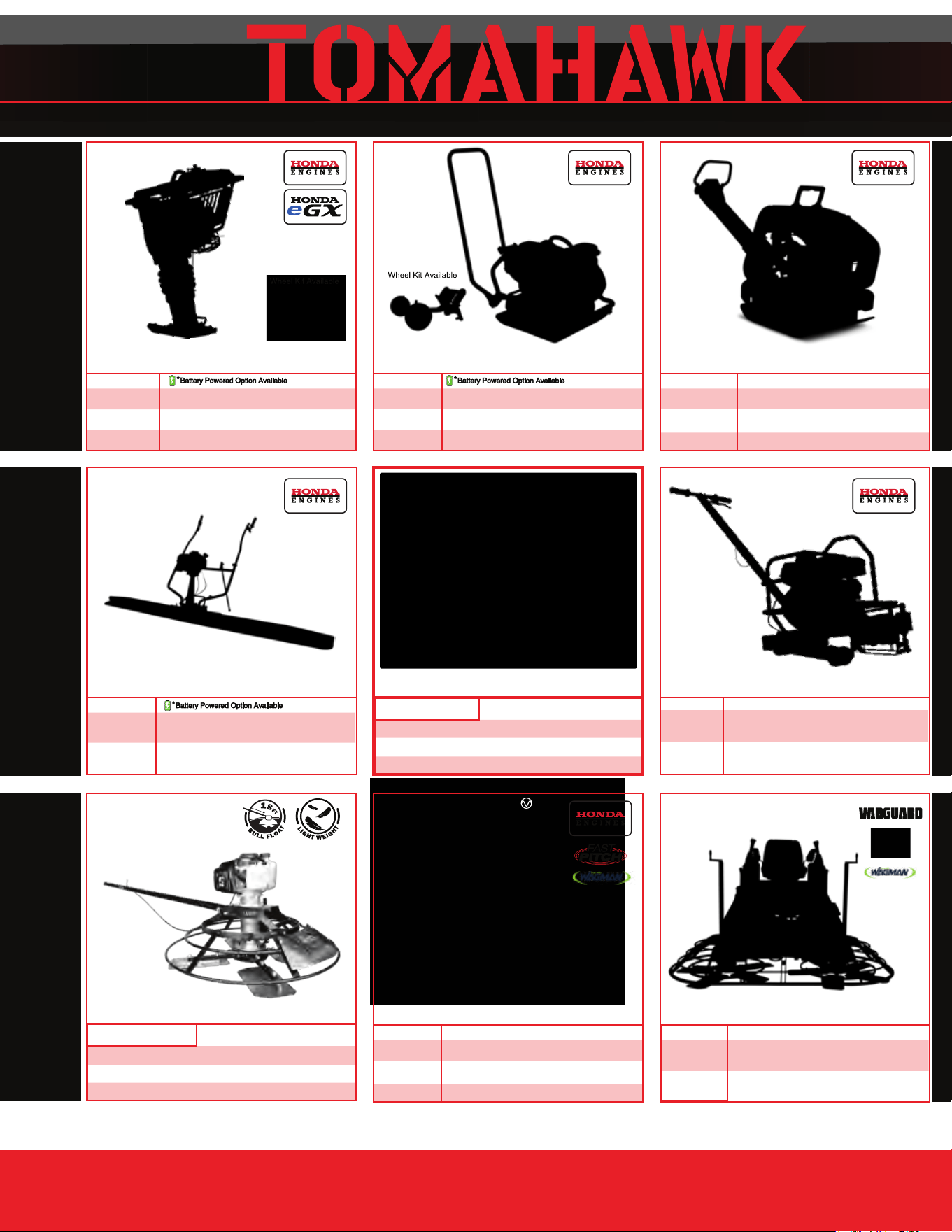
Rammers
8 ft Hydraulic Steer, 35 HP Vanguard,
CVT Clutch, 180 RPM
10 ft Full Hydrostatic, 74 HP Hatz
Diesel
Part#:
TPT24H
TPT36H
TPT46H
Part#: JXPT30T
Part#:
TRT46V
TRT60V
2 ft Edger, Honda GX160, 0-28
o
Blade Pitch
3 ft, Honda GX160/GX270, 0-28
o
Blade Pitch
4 ft, Honda GX270/GX390, 0-28
o
Blade Pitch
HAVE QUESTIONS?
Contact us. We’re here to help!
Email us at [email protected]
Forward Plate Compactors
Reverse Plate Compactors
Part#:
TR68H
JX60H
eJX60H
TVSA-H
eTVSA
Part#:
Part#:
TPC80H
COMPACTION
Power Screeds
Porta-Trowels
Concrete Sprayers
Walk Behind Trowels
Ride on Trowels
Early Entry Saws
Part#:
6-16 ft Magnesium Blades
Honda GX35, Adjustable Handles
6-16 ft Magnesium Blades
36V/5 Ah Battery, Adjustable Handles
Part#:
TFS6H
TFS10H
Part#: TCS6.5
6" Blade Diameter, Blade Compatibility,
Honda GX120
10" Blade Diameter, Self Propelled,
Blade Compatibility, Honda GX270/GX390
CONCRETETROWELS
(866) 577-4476
TPC85H
TPC90H
TPC170H
TPC100H
TPC400H
Equipment Guide
3,000 lbs/sq ft, Honda, 21”x17” Plate
3,200 lbs/sq ft, Honda, 23”x17” Plate
3,400 lbs/sq ft, Honda, 22”x20” Plate
3,500 lbs/sq ft, Honda, 19”×14” Plate
7,000 lbs/sq ft, Honda, 28”x20” Plate
11,690 lbs/sq ft, Honda, 32”x22” Plate
Lightweight at 40 lbs
Adjustable 18 ft Extension Bull Float Poles
30" Diameter, 4-Blade Assembly
Adjustable Blade Pitch from 0-28
o
Adjustable from 0-450 PSI
Handles 30% + Solids,1.8 HP 2 Stroke Motor,
24" Brass Wand 0.5 GPM, Fan Nozzle Included,
Spray
15,000 ft
2
in 10 Minutes
3,550 lbs/sq ft, Honda GX120
3,350 lbs/sq ft, Honda GX100
3,350 lbs/sq ft, Honda GXE2.0S
Items Listed Includes Combo Blades
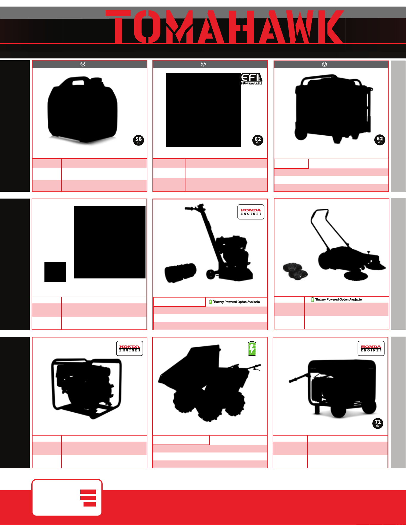
QUIET INVERTER SERIES
QUIET INVERTER SERIES
Welder GeneratorsPower Buggy
48V-20Ah Battery
Handles up to 8 cu ft or 660 lbs. Bucket Capacity
Hydraulic Bucket with 92
o
Tilt, 8 Hour Run Time
Snow Plow Attachment & Bucket Extender Available
Part#:
TGDR10
TSCP8
4,500 - 5,500 Watt Series
10,500 Watt Series
Concrete Scarifier
Floor Sweepers
Grinders and Scrapers
Part#: TSCAR-8H
Trash Water Pumps
Part#:
TW3H
TW4H
3" Pump, Honda GX270, 375 GPM,
Elevation: 89ft, Suction: 25ft
4" Pump, Honda GX390, 581 GPM,
Elevation: 92ft, Suction: 26ft
QUIET INVERTER SERIES
OUTDOOR POWER GENERATORSFLOORING
www.tomahawk-power.com
(866) 577-4476
ASSEMBLED IN THE
PARTS SOURCED GLOBALLY
USA
TG2000i
TG3000i
2,000 - 3,300 Watt Series
Equipment Guide
10" Disc, 120V, 1/32" Per Pass,
11 AMP, 1.5 HP, 1,725 RPM
8" Blade, 120V, 11 AMP, 3/4 HP,
1,725 RPM, Carpet & Tile Remover
Honda GX160 Engine, Scarifies 350 - 500ft
2
/hr
OSHA Compliant Vacuum Port
8" Carbide Tungsten Drum Kit, 1/8" Per Pass
38" Working Width, Triple Broom
System, 14.5 Gallon
30" Working Width, Battery Powered
Triple Broom System, 13.5 Gallon
120 Amp Welder, 60% Duty Cycle,
2000w, Includes Wheel Kit
210 Amp Welder, 60% Duty Cycle,
2000w, Includes Wheel Ki
t
4,500w Max / 3,800w Rated
5,500w Max / 5,000w Rated, 120/220V
Run Time 8 Hrs @ 50% Load
CARB Compliant, GFCI
TG4500i
TG5500i
10,500w Max / 8,500w Rated
Voltage Selector, 120/220V
Run Time 14.5hrs @ 25% Load
CARB Compliant,
GFCI, CO Detector
TG9000i
2,200w Max / 2,000w Rated
3,300w Max
/ 3,000w Rated,
120/220V, 30 AMP Twist Lock
Run Time 8 Hrs @ 50% Load
CARB Compliant, GFCI 120v
6010-7024 Rods Compatible
Part#: TBUGGY300e
Part#:
TWG120A
TWG210A
Part#:
TOS38
eTOS30
Assorted Blade Choices Assorted Blade Choices
Assorted Brush Choices

TOMAHAWK®, LLC
San Diego, CA
Sales Support
(866) 577-4476
Equipment Support
(866) 577-4476
www.tomahawk-power.com
Tomahawk understands to keep a job-site running smoothly the proper equipment and
spare parts are needed at the drop of a hat. With same day shipping and faster
delivery times, count on Tomahawk to keep you powered throughout the day! With
long lasting parts and engines, Tomahawk equipment will be the star of your fleet for
years to come. Visit www.tomahawk-power.com to get started today!
Power Your World
FACEBOOK
facebook.com/TomahawkPowerUSA
YOUTUBE
youtube.com/TomahawkPower
INSTAGRAM
@tomahawkpower