

20129
EN
Original Instructions
Version 1
450KG
ENGINE STAND

1.1 Product Reference
User Manual for: 450kg Engine Stand
Stock No: 20129
Part No: ES450B
1.2 Revisions
Version 1: March 2022
First release
As our manuals are continually updated, always ensure
that the latest version is used.
Download the latest version from:
drapertools.com/manuals
1.3 Understanding the Safety Content
WARNING! – Situations or actions that may result in
personal injury or death.
CAUTION! – Situations or actions that may result in
damage to the product or surroundings.
Important: – Information or instructions of particular
importance.
1.4 Copyright © Notice
Copyright © Draper Tools Limited.
Permission is granted to reproduce this manual for
personal and educational use ONLY. Commercial
copying, redistribution, hiring, or lending is strictly
prohibited.
No part of this manual may be stored in a retrieval system
or transmitted in any other form or means without written
permission from Draper Tools Limited.
In all cases, this copyright notice must remain intact.
1. Preface
– 2 –
These are the original product instructions. This
document is part of the product; retain it for the life
of the product, passing it on to subsequent holders.
Read this manual in full before attempting to
assemble, operate, or maintain this product.
This Draper Tools manual describes the purpose
of the product and contains all the necessary
information to ensure its correct and safe use.
Following all the instructions and guidance in
this manual will ensure the safety of both the
product and the operator and increase the
lifespan of the product.
All photographs and drawings within this manual are
supplied by Draper Tools to help illustrate correct
operation of the product.
Every eort has been made to ensure the
information contained in this manual is accurate.
However, Draper Tools reserves the right to amend
this document without prior warning. Always use the
latest version of the product manual.
EN

– 3 –
EN
2. Contents
1. Preface 2
1.1 Product Reference 2
1.2 Revisions 2
1.3 Understanding the Safety Content 2
1.4 Copyright © Notice 2
2. Contents 3
3. Warranty 4
4. Product Introduction 5
4.1 Scope 5
4.2 Specication 5
5. Health and Safety Information 6
6. Identication and Unpacking 7
6.1 Product Overview 7
6.2 What’s in The Box? 8
6.3 Packaging 8
7. Assembly Instructions 9
8. Mounting an Engine onto the Stand 10
9. Maintenance 11
10. Disposal 12
11. Explanation of Symbols 13

Draper Tools products are carefully tested and inspected
before shipment and are guaranteed to be free from
defective materials and workmanship.
Should the tool develop a fault, return the complete tool
to your nearest distributor or contact Draper Tools
directly. Contact information can be found at the back of
this manual.
Proof of purchase must be provided.
If, upon inspection, it is found that the fault occurring is
due to defective materials or workmanship, repairs will
be carried out free of charge. This warranty period covers
parts and labour for 12 months from the date of
purchase. Where tools have been hired out, the warranty
period covers 90 days from the date of purchase.
This warranty does not apply to any consumable parts,
batteries or normal wear and tear, nor does it cover any
damage caused by misuse, careless or unsafe handling,
alterations, accidents, or repairs attempted or made by
any personnel other than the authorised Draper Tools
repair agent.
In all cases, to make a claim for faulty workmanship or
materials within the standard warranty period, please
contact or return the product to the place of purchase.
Proof of purchase may be required.
If the place of purchase is no longer trading or if you
experience any diculties with your warranty, please
contact Customer Services with the product details and
your proof of purchase. Contact details can be found at
the back of this manual.
If the tool is not covered by the terms of this warranty,
repairs and carriage charges will be quoted and charged
accordingly.
This warranty supersedes any other guarantees
expressed or implied and variations of its terms are not
authorised.
Your Draper Tools guarantee is not eective until you can
produce, upon request, a dated receipt or invoice to
verify your purchase within the guarantee period.
Please note that this warranty is an additional benet
and does not aect your statutory rights.
Draper Tools Limited
– 4 –
3. Warranty
EN

Stock No. 20129
Part No. ES450B
Max. load 450kg
Dimensions (stand only) W 685 x H 850 x D 850mm
Net weight 20kg
4.2 Specication
4.1 Scope
This engine stand is designed to support a variety of
engines and transmissions during maintenance and
repair and is intended for domestic and light-duty trade
use. Any other application beyond the conditions
established for use will be considered misuse. Draper
Tools accepts no responsibility for improper use of this
product.
WARNING! This product is not a toy and must be
respected.
Read this manual in full before attempting to assemble,
operate or maintain the product, and retain it for later use.
4. Product Introduction
– 5 –
EN

Important: Read all Health and Safety instructions
before attempting to operate, maintain or repair this
product. Non-compliance with these instructions may
result in injury or damage to the user, the product or the
load.
• Observe all standard safety precautions and good
practices when working in a workshop environment.
• Keep your work environment clear and well-lit, with
bystanders at a safe distance.
• Assemble this product only in the manner depicted.
• Before every use, inspect the stand for broken or
cracked parts, loose xtures and binding wheels
WARNING! DO NOT use this product if its structural
integrity is compromised. Tighten, replace or repair
all aected parts before use.
• Only use this product on rm, level surfaces capable
of supporting both the stand and its load.
− DO NOT use this product on sloping or slippery
surfaces.
• DO NOT modify this product in any way.
• DO NOT climb on, ride on or allow others to ride on
this product.
• DO NOT attempt to move the stand under load over
cracked or uneven ooring.
− ALWAYS plan the route in advance and check it
for obstructions.
• NEVER exceed the rated capacity of this product.
• ALWAYS ensure that the load is mounted centrally on
the mounting plate.
− O-centre loads may cause the load to rotate
when the locking pin is released.
• ALWAYS lock the mounting plate in place before
transferring the load to the stand.
• NEVER work directly above or below the load; rotate
the load using the mounting plate handle and carry
out operations from the side.
• Take care when removing the locking pin and observe
the load at all times.
5. Health and Safety Information
– 6 –
EN
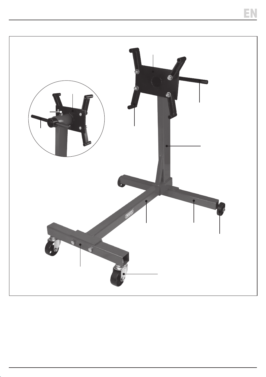
– 7 –
EN
(1) Mounting plate
(2) Mounting arms
(3) Mounting plate handle
(4) Locking pin
(5) Support column
(6) Rear crossbar
(7) Front crossbar
(8) Central arm
(9) Front castors
(10) Rear wheels
6.1 Product Overview
6. Identication and Unpacking
(6)
(2)
(3)
(10)
(8)
(7)
(3)
(9)
(5)
(1)
(1)
(4)

Please visit drapertools.com for our full range of accessories and consumables.
6.3 Packaging
Keep the product packaging for the duration of the
warranty period in case the product needs to be returned
for repair.
WARNING! Keep packaging materials out of reach of
children. Dispose of packaging correctly and
responsibly and in accordance with local regulations.
(A) 1 x Support column assembly
(B) 1 x Rear crossbar
(C) 1 x Front crossbar
(D) 1 x Central arm
(E) 2 x Front castors
(F) 2 x Rear wheels
(G) 1 x Mounting plate
(H) 1 x Mounting plate handle
(I) 4 x Mounting arms
(J) 3 x M12 x 80mm hex bolts
(K) 4 x M12 x 40mm hex bolts
(L) 2 x M14 washers
(M) 6 x M12 washers
(N) 9 x M12 spring washers
(O) 8 x M12 nuts
(P) 1 x Locking pin
(Q) 2 x Split pins
6.2 What’s in The Box?
Carefully remove the product from the packaging and
examine it for any signs of damage that may have
occurred during shipment.
Before assembling the product, lay the contents out and
check them against the parts listed below. If any part is
damaged or missing, do not attempt to use the product.
Please contact the Draper Helpline; contact details can
be found at the back of this manual.
(A)
(B)
(H)
(P)
(C)
(D)
(N, O)
(J)
(J, N)
(M, N, O )
(G)
(K, M)
(I)
(N, O)
(E)
(F, L, Q)
6. Identication and Unpacking
– 8 –
EN

Important: Read all the safety instructions before
attempting to assemble this product. Loosely secure all
xings during assembly and tighten once complete. Do
not overtighten joints and xings.
WARNING! The parts of this product are heavy. Seek
assistance when assembling the stand and do not
over-exert yourself.
1. Attach the rear crossbar (B) to the support column
assembly (A) and central arm (D):
a. Position the central arm so that the horizontal part
of the bracket is level with the top edge and feed
the square end into the square socket of the
central support arm.
b. Position the rear crossbar with the axles on the
lower edge and align it with the central support
column.
c. Pass an M12 x 80mm bolt (J) through an M12
spring washer (N), up through the base of the rear
crossbar and into the support column assembly,
tightening it to secure.
2. Attach the front crossbar (C) to the central arm:
a. Pass two M12 x 80mm bolts (J) through the front
crossbar and the central arm bracket.
b. Add an M12 washer (M) and an M12 spring washer
(N) to each bolt and tighten with an M12 nut (O).
3. Attach the front casters (E):
a. Pass the front caster bolts up through the base of
the front crossbar.
b. Add an M12 spring washer (N) to each bolt and
tighten with an M12 nut (O).
4. Place a rear wheel (F) onto each axle of the rear
crossbar and secure in place with an M14 washer (L)
and split pin (Q).
Important: The rear wheels should be positioned so
that the deeper wheel hub is facing inwards.
5. Attach the mounting plate (G):
a. Slide the mounting plate through the support
column socket so that the plate is positioned above
the central arm.
b. Pass the mounting plate handle (H) through the
opening in the mounting plate stem.
c. Insert the locking pin (P) to secure the mounting
plate in position.
d. Pass four M12 x 50mm bolts (K) through the back
of the mounting plate and attach a mounting arm
(I) to each.
e. Secure each mounting arm in place with an M12
washer (M), an M12 spring washer (N) and an M12
nut (O).
6. Check that the stand frame is not twisted and that all
four wheels are touching the ground, then tighten all
attachments.
7. Assembly Instructions
– 9 –
EN

Important: Before attaching any load, read and
understand all the safety instructions listed in this
manual. ALWAYS ensure that the xing bolts used to
attach the load are of an appropriate length and grade.
1. Raise the load with an appropriate hoist and position
the engine stand nearby.
2. Remove the mounting plate handle (H) and locking
pin (P) and slide the mounting plate (G) away from the
stand.
3. Pass the xing bolts through the back of the
mounting arms and screw them into the mounting
sockets on the load.
Important: Bolt the bottom two arms low on the load
and the top two arms as high as possible. The bolts
must be long enough to be wound at least 25mm into
the load when mounted. Draper Tools recommends
metric grade 8.8 bolts for mounting engines.
4. Adjust the mounting arms so that the centre of the
mounting plate is aligned with the centre of the
engine crankshaft and tighten all bolts securely.
5. Lower the load until the mounting plate stem aligns
with the socket on the support column assembly (A)
and slide it into place.
6. Insert the mounting plate handle and locking pin to
secure the mounting plate in place.
7. Use the hoist to lower the load and carefully transfer
the weight to the engine stand.
8. Check that all attachments are secure and that the
stand can support the load without intervention, then
disengage the hoist.
9. To rotate the load:
a. Remove the locking pin and use the mounting
plate handle to turn the load into the correct
position.
b. Reinsert the locking pin when the load is in the
required position; four positions are available.
8. Mounting an Engine onto the Stand
– 10 –
EN

9. Maintenance
Important: Maintenance and repairs should ONLY be
carried out by authorised and suitably qualied
personnel.
• Regularly check the product for damage, corrosion
and loose xings, and keep xings securely fastened.
• Periodically lubricate all wheel attachments to ensure
smooth movement.
• Store the engine stand in a dry and clean location, out
of reach of children.
– 11 –
EN

10. Disposal
– 12 –
EN
At the end of its working life, or when it can no longer be
repaired, dispose of the product according to local
regulations.
Contact your local authority for details of collection
schemes in your area.
In all circumstances:
• DO NOT incinerate
• DO NOT abandon in the environment

11. Explanation of Symbols
Read the instruction manual
Warning!
Do not incinerate or throw onto re
Do not abandon in the environment
450
KG
Product weight (bare)
– 13 –
EN

Contact Details
Draper Tools
Draper Tools Limited
Hursley Road
Chandler’s Ford
Eastleigh
Hampshire
SO53 1YF
UK
Website: drapertools.com
Email: [email protected]
Product Helpline: +44 (0) 23 8049 4344
Telephone Sales Desk: +44 (0) 23 8049 4333
General Enquiries: +44 (0) 23 8026 6355
General Fax: +44 (0) 23 8026 0784
Service / Warranty Repair Agents
For aftersales servicing or warranty repairs, please contact the Draper Tools Product
Helpline for details of an agent in your area.
© Published by Draper Tools Limited
Delta International
Delta International BV
Oude Graaf 8
6002 NL
Weert
Netherlands