Page 1
241-0437
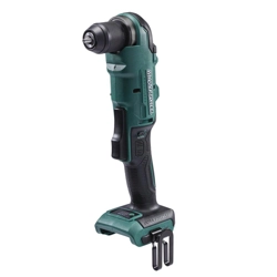
Right Angle Drill
ULTRA
COMPACT
CAUTION:
To Reduce The Risk Of Injury, User Must
Read And Understand Operator’s Manual. Save These
Instructions For Future Reference.
For questions / comments, technical assistance or repair parts –
Please Call Toll Free: 1-866-917-4374. (M-F 8:30am-5:00pm EST).
OPERATOR’S MANUAL

Page 2
TABLE OF CONTENTS
Safety Symbols ..........................................................Page 2
Safety Instructions .......................................................Page 3
Overview/Specifications ..................................................Page 8
Assembly ..............................................................Page 9
Operation ..............................................................Page 9
Maintenance ...........................................................Page 14
Troubleshooting ........................................................Page 15
Parts List ..............................................................Page 16
Schematic Drawing .....................................................Page 17
Warranty ..............................................................Page 18
Page 2
SAFETY SYMBOLS
Some of these following symbols may be used on this tool. Please study them and learn their
meaning. Proper interpretation of these symbols will allow you to operate the tool better and
more safely.
Symbol
Name
Designation / Explanation
V Volts Voltage
A Amps Current
Hz Hertz Frequency (cycles per second)
W Watts Power
lbs Pounds Weight
n
0
No-load speed Rotational speed at no load
…/min Per minute
Revolutions, strokes, surface speed
orbits, etc., per minute
� or d.c.
Direct current Type of characteristic of current
Read instruction
manual
To reduce the risk of injury, user must
read instruction manual.
Wear safety goggles
WARNING:
The operation of any
power tool can result in foreign objects
being thrown into your eyes, which can
result in severe eye damage. Before
beginning power tool operation, always
wear safety goggles or safety glasses
with side shields and a full-face shield
when needed. We recommend a Wide
Vision Safety Mask for use over eye-
glasses or standard safety glasses with
side shields. Always use eye protection
which is marked to comply with ANSI
Z87.1.
WARNING:
To ensure safety and reliability, all repairs should be performed by a
qualied service technician.

Page 3
SAFETY INSTRUCTIONS
The purpose of safety symbols is to attract your attention to possible dangers. The safety
symbols and the explanations with them deserve your careful attention and understanding.
The symbol warnings do not, by themselves, eliminate any danger. The instructions and
warnings they give are no substitutes for proper accident prevention measures.
WARNING:
Be sure to read and understand all safety instructions in this manual,
including all safety alert symbols such as “DANGER,” ”WARNING,” and “CAUTION”
before using this tool. Failure to follow all instructions listed below may result in electric
shock, re, and/or serious personal injury.
SYMBOL MEANING
SAFETY ALERT SYMBOL: Indicates DANGER, WARNING, OR CAUTION.
May be used in conjunction with other symbols or pictographs.
DANGER:
Indicates an imminently hazardous situation, which, if not avoided,
will result in death or serious injury.
WARNING:
Indicates a potentially hazardous situation, which, if not avoided,
could result in death or serious injury.
CAUTION:
Indicates a potentially hazardous situation, which, if not avoided, could
result in minor or moderate injury.
NOTICE: (Without Safety Alert Symbol) Indicates a situation that may result in property
damage.
SAVE THESE INSTRUCTIONS!

Page 4
SAFETY INSTRUCTIONS
GENERAL POWER TOOL SAFETY
WARNINGS
WARNING:
Read all safety
warnings, instructions, illustrations and
specications provided with this power
tool. Failure to follow all instructions listed
below may result in electric shock, fire and/
or serious injury.
SAVE ALL WARNINGS AND INSTRUCTIONS
FOR FUTURE REFERENCE.
The term “power tool” in the warnings refers
to your mains-operated (corded) power tool
or battery-operated (cordless) power tool.
WORK AREA SAFETY
1. Keep work area clean and well lit.
Cluttered or dark areas invite accidents.
2. Do not operate power tools in explosive
atmospheres, such as in the presence of
ammable liquids, gases or dust. Power
tools create sparks which may ignite the
dust or fumes.
3. Keep children and bystanders away
while operating a power tool. Distractions
can cause you to lose control.
ELECTRICAL SAFETY
1. Power tool plugs must match the
outlet. Never modify the plug in any way.
Do not use any adapter plugs with earthed
(grounded) power tools. Unmodified plugs
and matching outlets will reduce risk of
electric shock.
2. Avoid body contact with earthed
or grounded surfaces, such as pipes,
radiators, ranges and refrigerators. There
is an increased risk of electric shock if your
body is earthed or grounded.
3. Do not expose power tools to rain or
wet conditions. Water entering a power tool
will increase the risk of electric shock.
4. Do not abuse the cord. Never use the
cord for carrying, pulling or unplugging the
power tool. Keep cord away from heat, oil,
sharp edges or moving parts. Damaged or
entangled cords increase the risk of electric
shock.
5. When operating a power tool outdoors,
use an extension cord suitable for outdoor
use. Use of a cord suitable for outdoor use
reduces the risk of electric shock.
6. If operating a power tool in a damp
location is unavoidable, use a ground fault
circuit interrupter (GFCI) protected supply.
Use of an GFCI reduces the risk of electric
shock.
PERSONAL SAFETY
1. Stay alert, watch what you are doing
and use common sense when operating a
power tool. Do not use a power tool while
you are tired or under the inuence of
drugs, alcohol or medication. A moment of
inattention while operating power tools may
result in serious personal injury.
2. Use personal protective equipment.
Always wear eye protection. Protective
equipment such as a dust mask, non-skid
safety shoes, hard hat or hearing protection
used for appropriate conditions will reduce
personal injuries.
3. Prevent unintentional starting. Ensure
the switch is in the off-position before
connecting to power source and/or battery
pack, picking up or carrying the tool.
Carrying power tools with your finger on the
switch or energizing power tools that have
the switch on invites accidents.
4. Remove any adjusting key or wrench
before turning the power tool on. A wrench
or a key left attached to a rotating part of the
power tool may result in personal injury.
5. Do not overreach. Keep proper footing
and balance at all times. This enables better
control of the power tool in unexpected
situations.

Page 5
SAFETY INSTRUCTIONS
6. Dress properly. Do not wear loose
clothing or jewelry. Keep your hair and
clothing away from moving parts. Loose
clothes, jewelry or long hair can be caught
in moving parts.
7. If devices are provided for the
connection of dust extraction and
collection facilities, ensure these are
connected and properly used. Use of dust
collection can reduce dust-related hazards.
8. Do not let familiarity gained from
frequent use of tools allow you to become
complacent and ignore tool safety
principles. A careless action can cause
severe injury within a fraction of a second.
POWER TOOL USE AND CARE
1. Do not force the power tool. Use the
correct power tool for your application. The
correct power tool will do the job better and
safer at the rate for which it was designed.
2. Do not use the power tool if the switch
does not turn it on and off. Any power tool
that cannot be controlled with the switch is
dangerous and must be repaired.
3. Disconnect the plug from the power
source and/or remove the battery pack,
if detachable, from the power tool before
making any adjustments, changing
accessories, or storing power tools. Such
preventive safety measures reduce the risk
of starting the power tool accidentally.
4. Store idle power tools out of the reach
of children and do not allow persons
unfamiliar with the power tool or these
instructions to operate the power tool.
Power tools are dangerous in the hands of
untrained users.
5. Maintain power tools and accessories.
Check for misalignment or binding of
moving parts, breakage of parts and any
other condition that may affect the power
tool’s operation. If damaged, have the
power tool repaired before use. Many
accidents are caused by poorly maintained
power tools.
6. Keep cutting tools sharp and clean.
Properly maintained cutting tools with sharp
cutting edges are less likely to bind and are
easier to control.
7. Use the power tool, accessories
and tool bits etc. in accordance with
these instructions, taking into account
the working conditions and the work to
be performed. Use of the power tool for
operations different from those intended
could result in a hazardous situation.
8. Keep handles and grasping surfaces
dry, clean and free from oil and grease.
Slippery handles and grasping surfaces do
not allow for safe handling and control of the
tool in unexpected situations.
BATTERY TOOL USE AND CARE
1. Recharge only with the charger
specied by the manufacturer. A charger
that is suitable for one type of battery pack
may create a risk of fire when used with
another battery pack.
2. Use power tools only with specically
designated battery packs. Use of any other
battery packs may create a risk of injury and
fire.
3. When battery pack is not in use, keep
it away from other metal objects, like
paper clips, coins, keys, nails, screws or
other small metal objects, that can make
a connection from one terminal to another.
Shorting the battery terminals together may
cause burns or a fire.
4. Under abusive conditions, liquid may
be ejected from the battery; avoid contact.
If contact accidentally occurs, ush with
water. If liquid contacts eyes, additionally
seek medical help. Liquid ejected from the
battery may cause irritation or burns.
5. Do not use a battery pack or tool that
is damaged or modied. Damaged or
modified batteries may exhibit unpredictable
behavior resulting in fire, explosion or risk of
injury.

Page 6
SAFETY INSTRUCTIONS
6. Do not expose a battery pack or tool
to re or excessive temperature. Exposure
to fire or temperature above 265°F (130 °C)
may cause explosion.
7. Follow all charging instructions and
do not charge the battery pack or tool
outside the temperature range specied
in the instructions. Charging improperly or
at temperatures outside the specified range
may damage the battery and increase the
risk of fire.
SERVICE
1. Have your power tool serviced by a
qualied repair person using only identical
replacement parts. This will ensure that the
safety of the power tool is maintained.
2. Never service damaged battery
packs. Service of battery packs should
only be performed by the manufacturer or
authorized service providers.
DRILL SAFETY WARNINGS
SAFETY INSTRUCTIONS FOR
ALL OPERATIONS
1. Hold the power tool by insulated
gripping surfaces, when performing an
operation where the cutting accessory
or fasteners may contact hidden wiring.
Cutting accessory or fasteners contacting a
“live” wire may make exposed metal parts
of the power tool “live” and could give the
operator an electric shock.
SAFETY INSTRUCTIONS WHEN
USING LONG DRILL BITS
1. Never operate at higher speed than
the maximum speed rating of the drill bit.
At higher speeds, the bit is likely to bend if
allowed to rotate freely without contacting the
workpiece, resulting in personal injury.
2. Always start drilling at low speed
and with the bit tip in contact with the
workpiece. At higher speeds, the bit is
likely to bend if allowed to rotate freely
without contacting the workpiece, resulting in
personal injury.
3. Apply pressure only in direct line
with the bit and do not apply excessive
pressure. Bits can bend causing breakage
or loss of control, resulting in personal injury.
Page 7
IMPORTANT SAFETY INSTRUCTIONS
1. To reduce the risk of electric shock or
damage to the chargers and batteries, use
only with the MASTERFORCE
®
20V battery
packs and chargers listed.
Battery pack Charger
252-8029 (1.5Ah)
252-8031 (2.0Ah)
252-8030 (2.5Ah)
252-8003 (2.5Ah)
252-8034 (4.0Ah)
252-8013 (4.0Ah)
252-8035 (5.0Ah)
252-8005 (5.0Ah)
252-8007 (7.5Ah)
252-8014 (8.0Ah)
252-8025 (45W)
252-8023 (60W)
252-8037 (90W)
252-8026 (150W)
252-8043 (2×150W)
2. For best results, your battery and tool
should be stored, charged and used in a
location where the temperature is more
than 41°F (5°C) but less than 104°F (40°C).
Do not store outside or in vehicles.
DANGER:
People with electronic
devices, such as pacemakers, should
consult their physician(s) before using this
product. Operation of electrical equipment
in close proximity to a heart pacemaker
could cause interference or failure of the
pacemaker.
WARNING:
• Some dust created by power sanding,
sawing, grinding, drilling, and other
construction activities contains chemicals
known to the state of California to cause
cancer, birth defects, or other reproductive
harm. Some examples of these chemicals
are:
–Lead from lead-based paints
–Crystalline silica from bricks, cement, and
other masonry products
–Arsenic and chromium from chemically-
treated lumber
• Your risk from these exposures varies,
depending upon how often you do this type
of work. To reduce your exposure to these
chemicals:
–Work in a well-ventilated area.
–Work with approved safety equipment,
such as dust masks that are specially
designed to lter out microscopic particles.
–Avoid prolonged contact with dust from
power sanding, sawing, grinding, drilling,
and other construction activities. Wear
protective clothing and wash exposed
areas with soap and water. Allowing dust
to get into your mouth or eyes or to lie
on the skin may promote absorption of
harmful chemicals.
SAVE THESE INSTRUCTIONS!
SAFETY INSTRUCTIONS
Page 8
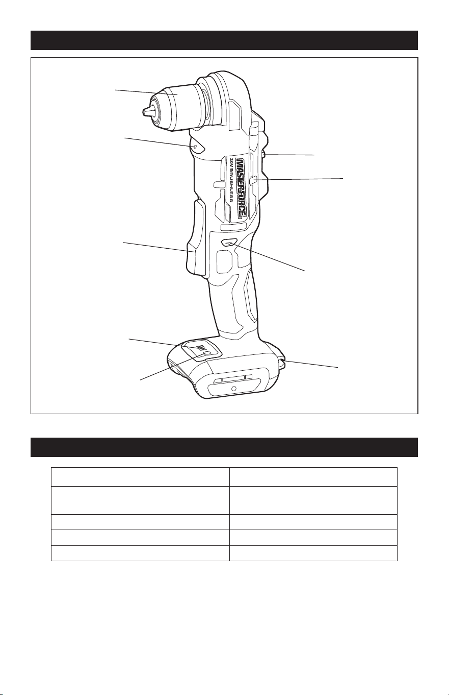
OVERVIEW
ULTRA
COMPACT
1
2
3
D
Keyless Chuck
LED Worklight
Variable-speed
Trigger Switch
Bit Storage
Direction-of-rotation
Selector(Forward/
Center-lock/Reverse)
Vents
SPECIFICATIONS
Rated Voltage 20 V d.c.
No-load Speed
1: 0-650 /min
2: 0-2200 /min
Chuck Capacity 3/8”
Max. Torque 350 in. lbs.
Weight (without battery) 2 lbs. 9 oz.
Torque Indicator
Torque Button
Gear Selector
Page 9
ASSEMBLY
OPERATION
WARNING:
If any part is broken
or missing, DO NOT attach the battery
pack or operate the tool until the broken
or missing part is replaced. Failure to do so
could result in possible serious injury.
WARNING:
Do not attempt to
modify this tool or create accessories not
recommended for use with this tool. Any
such alteration or modication is misuse
and could result in a hazardous condition
leading to possible serious injury.
WARNING:
Your tool should
never be connected to the battery pack
when you are assembling parts, making
adjustments, cleaning, or when it is not in
use. Disconnecting the tool will prevent
accidental starting, which could cause
serious personal injury.
PACKING LIST
- Right angle drill
- Double end bit
- Belt clip
- Screw for the belt clip
- Instruction manual
UNPACKING
1. Carefully remove the tool and any
accessories from the carton. Make sure
that all items listed in the packing list are
included.
2. Inspect the tool carefully to make sure
that no breakage or damage occurred
during shipping.
3. Do not discard the packing material
until you have carefully inspected and
satisfactorily operated the tool.
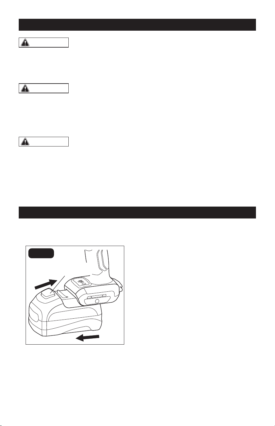
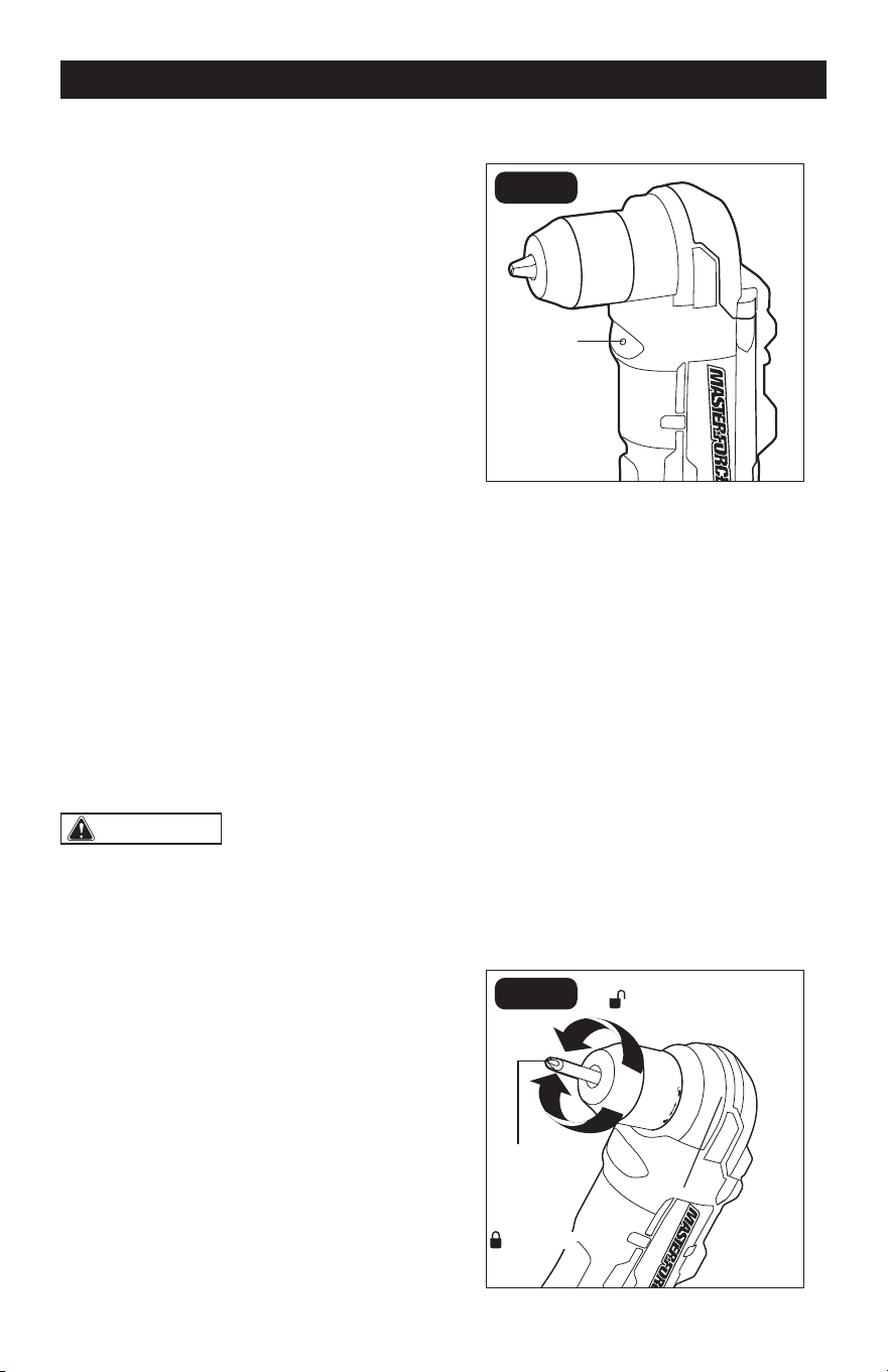
ATTACH THE BATTERY PACK
(FIG. 1)
1
D
FIG. 1
1.
Align the raised ribs on the battery pack
with the grooves on the bottom of the tool,
then slide the battery pack onto the tool.
2. Ensure that the battery-release button
on the battery pack snaps into place
and the battery pack is secured to the
tool before beginning operation.
NOTICE: When placing the battery pack on
the tool, be sure that the raised ribs on the
battery pack align with the grooves on the
tool and the latch snaps into place properly.
Improper assembly of the battery pack can
cause damage to internal components.
DETACH THE BATTERY PACK
(FIG. 1)
1. Press the battery-release button to
release the battery pack.
2. Pull the battery pack to remove it from
the tool.
ASSEMBLY
OPERATION
Attach
Battery-release
Button
Detach
Page 10
OPERATION
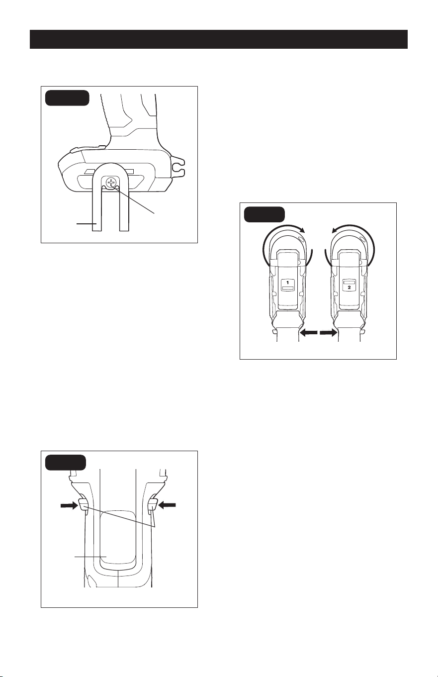
INSTALLING THE BELT CLIP
(FIG. 2)
FIG. 2
Screw
1. Remove the battery from the tool.
2. Align the rib of the belt clip with the hole
on the base of the drill.
3. Insert the screw and securely tighten
the screw with a screwdriver.
REMOVING THE BELT CLIP
(FIG. 2)
1. Remove the battery from the tool.
2. Use a screwdriver to loosen the screw
that attaches the belt clip to the drill.
3. Remove the screw and the belt clip.
TRIGGER SWITCH (FIG. 3)
FIG. 3
Variable-
speed
Trigger
Switch
To turn the drill ON, depress the trigger switch.
To turn it OFF, release the trigger switch.
VARIABLE SPEED (FIG. 3)
The variable-speed trigger switch delivers
higher speed with increased trigger pressure
and lower speed with decreased trigger
pressure.
DIRECTION-OF-ROTATION SE-
LECTOR (FORWARD/CENTER-
LOCK/REVERSE) (FIG. 4)
FIG. 4
REVERSEFORWARD
The direction of rotation is reversible and is
controlled by a selector located above the
trigger switch. With the drill held in normal
operating position:
1. Position the direction-of-rotation selector
to the left of the tool for forward rotation.
2. Position the direction-of-rotation selector
to the right of the tool for reverse rotation.
3. Setting the selector in the center-lock
position helps reduce the possibility of
accidental starting when the tool is not in use.
NOTICE:
• To prevent gear damage, always allow the
right angle drill to come to a complete stop
before changing the direction of rotation.
• The right angle drill will not run unless the
direction-of-rotation selector is engaged
fully to the left or right.
Belt Clip
Direction-
of-rotation
Selector
Page 11
OPERATION OPERATION
ELECTRIC BRAKE
To stop the right angle drill, release the
trigger switch and allow the tool to come to
a complete stop. The electric brake quickly
stops the chuck rotation. This feature
engages automatically when you release the
trigger switch.
TWO-SPEED GEAR SELECTOR
(FIG. 5)
FIG. 5
1(LOW) 2 (HIGH)
The right angle drill has a two-speed gear
box designed for drilling or driving at either
of two different variable-speed ranges. A
gear selector is located on the top of the drill
to select either 1 (Low) or 2 (High) speed.
Setting 1 will deliver lower speeds and
increased power and torque. Use setting 1
for heavy-duty work or for driving screws.
Setting 2 will deliver higher speeds and
reduced power and torque. Use setting
2 for drilling wood and wood composites
and for using abrasive and polishing
accessories.
NOTICE:
Never change gears while the tool is
running. Failure to obey this caution could result
in serious damage to the right angle drill.
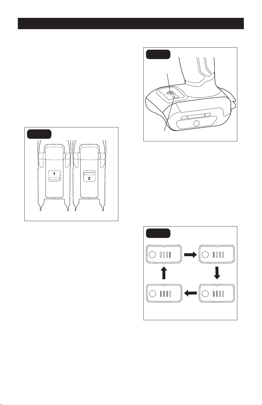
ADJUSTABLE TORQUE (FIG. 6)
1
D
FIG. 6a
Torque
Indicator
Torque Button
The right angle drill torque can be adjusted
among 3 driving settings and 1 drilling setting.
The tool defaults to the drill mode. When the
variable-speed trigger switch is first pressed,
a green light will shine in the torque indicator
to indicate that the tool is in drill mode.
Press the torque button one time to adjust
the tool to the drive setting.
1:Lowest torque.
2:Medium torque.
3:Maximum torque.
1 2 3
D
1 2 3
D
1 2 3
D
1 2 3
D
FIG. 6b
The higher the torque setting, the more
force the right angle drill produces to turn
an object. The proper setting depends on
the job and the type of bit, fastener, and
material you will be using. If the torque is
too high, the screws may be damaged or
broken.
Select the drill mode for drilling and other
heavy-duty applications.
Page 12
OPERATION
1. The torque indicator lights will blink to
indicate that the set torque is reached
when in torque settings 1, 2, or 3.
2. Attach the battery pack to the tool.
Position the direction-of-rotation
selector to the left side of the tool for
forward rotation, and briefly press the
trigger switch to turn on the torque
indicator lights. The torque indicator
lights will be set at the drilling mode “D”.
3. The indicator lights will convert to the
drilling mode “D” when the direction-
of-rotation selector is set to the reverse
direction, and will revert to the previous
setting when the selector is moved
back to the forward direction before the
indicator lights turn off.
4. The indicator lights will turn off
approximately 1 minute after the
variable-speed trigger switch is
released. If the user presses the torque
button within 1 minute after releasing
the trigger switch, the indicator lights
will continue to shine for 1 minute again.
5. The torque indicator lights will be set at
the drilling mode “D” each time when
you reattach the battery back or restart
the tool after the indicator lights turn off.
WARNING:
• Do not change the torque setting when
the tool is operating.
• Watch out for the torque indicator lights
before operating the tool to reduce the risk
of injury or damage to the workpiece.
LED WORKLIGHT (FIG. 7)
20V BRUSHLESS
FIG. 7
The LED worklight, located on the front of the
drill, will illuminate before the trigger switch
is fully depressed. This provides additional
light on the surface of the workpiece for
operation in lower-light areas.
The LED worklight will automatically turn off
within 10 seconds after the trigger switch is
released.
1. The LED worklight will blink rapidly if
the tool has stopped working in order
to protect internal circuits. Wait for the
tool to cool down, after which it can be
started again.
2. The LED worklight will blink slowly to
indicate that the battery charge is very
low.
INSTALLING BITS (FIG. 8)
20V BRUSHLESS
FIG. 8
Drill Bit
(Tighten)
(Release)
LED
Worklight
Page 13
OPERATION
1. Lock the trigger switch by placing the
direction-of-rotation selector in center
(OFF) position.
2. Open or close the chuck jaws to a point
where the opening is slightly larger than
the bit size you intend to use. Also, raise
the front of the drill slightly to keep the
bit from falling out of the chuck jaws.
3. Insert the drill bit straight into the chuck
the full length of the jaws.
4. To tighten: grasp and hold the tool with
one hand, while rotating the chuck with
your other hand.
NOTICE: Rotate the chuck in the direction
of the arrow marked to tighten the chuck
jaws. Do not use a wrench to tighten or
loosen the chuck jaws.
WARNING:
Do not hold the chuck
with one hand and use the power of the drill
to tighten the chuck jaws on the drill bit. The
chuck could slip in your hand, or your hand
could slip and come in contact with the
rotating bit. This could cause an accident
resulting in serious personal injury.
WARNING:
Make sure to insert the
drill bit straight into the chuck jaws. Do
not insert the drill bit into the chuck jaws
at an angle, and then tighten. This could
cause the drill bit to be ejected from the
drill, resulting in possibly serious personal
injury or damage to the chuck.
REMOVING BITS (FIG. 8)
1. Lock the trigger switch by placing the
direction-of-rotation selector in center
position.
2. To loosen the chuck jaw: grasp and hold
the tool with one hand, while rotating
the chuck with your other hand.
NOTICE: Rotating the chuck in the direction
of the arrow marked to loosen the chuck
jaws. Do not use a wrench to tighten or
loosen the chuck jaws.
3. Remove the drill bit from the chuck jaws.
WARNING:
The bit may be hot after
use. Wear protective gloves or wait until the
bit has cooled down before removing the bit.
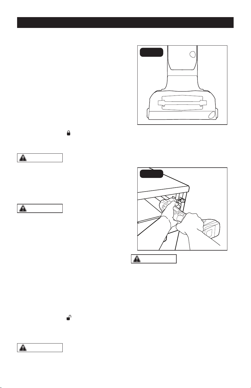
BIT STORAGE (FIG. 9)
FIG. 9
When not in use, bits can be placed in the
storage area located on the base of the drill.
DRILLING (FIG. 10)
FIG. 10
WARNING:
Hold drill with both
hands during operation. Failure to hold the
drill with both hands during operation could
lead to loss of control and result in injury.
When drilling hard, smooth surfaces, use
a center punch to mark the desired hole
location. This will prevent the drill bit from
slipping off center as the hole is started.
The material to be drilled should be
secured in a vise or with clamps to keep
it from turning as the drill bit rotates. Hold
the tool firmly and place the bit at the point
to be drilled. Depress the trigger switch to
start the tool.
Move the drill bit into the workpiece,
applying only enough pressure to keep
Page 14
OPERATION
the bit cutting. Do not force or apply side
pressure to elongate a hole.
WARNING:
Be prepared for
binding at bit breakthrough. When these
situations occur, the drill has a tendency
to grab and kick opposite to the direction
of rotation and could cause loss of control
when breaking through the material. If not
prepared, this loss of control can result in
possibly serious injury.
When drilling metals, use light oil on the drill
bit to keep it from overheating. The oil will
prolong the life of the bit and increase the
drilling action.
If the bit jams in workpiece or if the drill stalls,
release trigger switch immediately. Remove
the bit from the workpiece and determine the
reason for jamming.
SCREW DRIVING
1. Try to use appropriate screws for easy
driving and improved grip.
2. It is advisable to drill a pilot hole first.
The pilot hole will act as a guide for the
screw and will also make tightening the
screw less difficult.
3. Set the torque button to the most
suitable setting. If in doubt, start with
a low setting, then turn off the tool and
increase the setting as needed.
NOTICE: Do not change the torque setting
when the tool is running.
4. Keep sufficient pressure on the drill to
prevent the bit from turning out of the
screw head. The screw head can easily
become damaged, making it difficult to
drive it home or remove it.
MAINTENANCE
1. Check for damaged, missing, or worn
parts.
2. Check for loose screws, misalignment
or binding of moving parts, or any other
condition that may affect the operation.
3. If abnormal vibration or noise occurs,
turn the tool off immediately and have
the problem corrected before further
use.
4. Using compressed air may be the most
effective cleaning method. Always wear
safety goggles when cleaning tools
using compressed air.
5. Store the tool indoors in a place that
is inaccessible to children. Keep away
from corrosive agents.
6. Avoid using solvents when cleaning
plastic parts. Most plastics are
susceptible to damage from various
types of commercial solvents. Use clean
cloths to remove dirt, dust, oil, grease,
etc.
WARNING:
• To avoid serious personal injury, always
remove the battery pack from the tool when
cleaning or performing any maintenance.
• When servicing, use only identical
replacement parts. Use of any other parts
may create a hazard or cause product
damage. To ensure safety and reliability, all
repairs should be performed by a qualied
service technician at an Authorized Service
Center.
Page 15
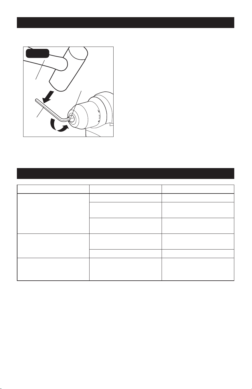
CHUCK REMOVAL (FIG. 11)
FIG. 11
Mallet
Hex Key
Chuck Jaws
The chuck can be removed and replaced.
1. Remove the battery. Lock the trigger
switch by placing the direction-of-
rotation selector in the center (OFF)
position.
2. Rotate the chuck to open the chuck
jaws.
3. Use a Philips screwdriver (available
separately) to remove the chuck screw
by turning it clockwise.
4. Insert the hex key in chuck and tighten
the chuck jaws securely. Tap sharply
with a mallet in a counterclockwise
direction. This will loosen the chuck on
the spindle. It can now be unscrewed by
hand.
NOTICE: The chuck screw has left handed
threads. Attach a new chuck to the spindle
and tighten the chuck screw.
MAINTENANCE
TROUBLESHOOTING
PROBLEM POSSIBLE CAUSE SOLUTION
The drill does not work.
Battery is depleted. Charge the battery.
Battery or the tool is
overheated.
Allow the battery or the tool
to cool down.
The tool is overloaded.
Restart the tool and do not
force the tool.
Bit cannot be installed.
Chuck is not sufficiently
open.
Open the chuck.
Bit does not fit the chuck. Use the appropriate bits.
Motor overheating.
Cooling vents are
obstructed.
Clean, clear vents. Do not
cover with hand during
operation.

Page 16
PARTS LIST
No. Part Name No. Part Name
1 Screw (L.H.) 10 Cover Plate
2 Chuck 11 Rubber Push Button
3 Gear Case ASSY 12 Indicator Label
4 Speed Change Button 13 F/R Button
5 Motor & Gear Assembly 14 Switch Trigger
6 Stator 15 Hook
7 Housing Assembly 16 Screw
8 Screw 17 Screw Bit
9 Main Electric Assembly
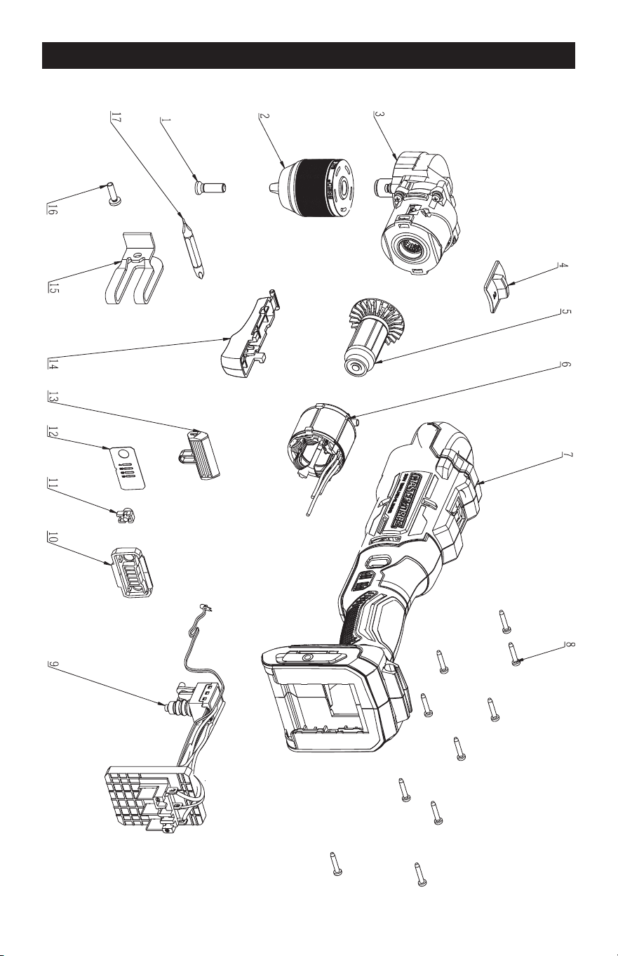
Page 17
SCHEMATIC DRAWING

Page 18
Right Angle Drill

Page 19
05/2025
© 2025 Menard, Inc., Eau Claire, WI 54703