Version 1.4
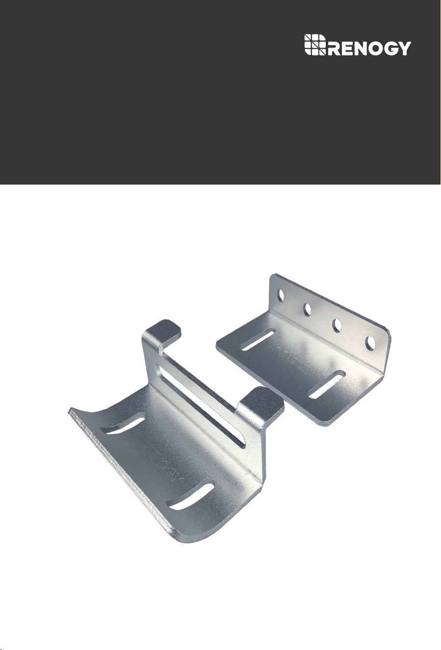
RENOGY Photovoltaic Module Adjustable Curved Bracket
RENOGY
MTS-ACB
02
General Safety Information
Installer Responsibilities
Important Safety Instructions
Please save these instructions.
Installation should be completed by a professional contractor to avoid damages that may
be incurred due to improper sealing.
Do NOT substitute parts from other manufacture ring sources, doing so may void the
warranty and/or result in an unstable system
This system does NOT possess any compliance with residential structural codes and
should not be used in place of a system that is, if required by local regulations
Read all of the instructions and cautions in the manual before beginning the installation.
Installation compliance and compatibility with all system components and the environment
including but not limited to roofing, system components, etc.
Verification that all project information is accurate
Installation compliance with any applicable codes which are in force at the installation site
NOTE
CAUTION
WARNING
Indicates a potentially dangerous condition. Use extreme caution when
performing this task.
This manual contains important safety, installation, and operating instructions for the
Renogy Adjustable Curved Bracket Mount hardware system. The following symbols are
used throughout the manual to indicate potentially dangerous conditions or important
safety information.
Indicates a critical procedure for safe and proper operation of the
system.
Indicates a procedure or function that is important to the safe and
proper operation of the system.

03
Table of Contents
General Information
Identification of Parts
Installation
Mating Brackets to Panel Frame
Install Panel to General Flat Mounting Surface
04
05
07
Adjustable Curved Bracket Dimensions
28
Compatibility
30
09
14
Install Panel to Flat RV Roofs
Install Panel to General Mounting Curved Surface
19
27

04
General Information
The Renogy Adjustable Curved Brack
et Mount System is designed to support the installation
of single panel units, generally in off-grid installations. The unique design enables these units to
support solar panels on curved surfaces, such as those found on Airstreams and other types of
RVs. The system comes complete with all fasteners to secure the system to the installation
surface. This system makes the installation of small solar systems easy, affordable and quick.
Key Features
Lightweight
Aluminum corrosion-free construction
Ideal for RV’s and boats
Fits to curved surface. Accept about 30°curve.
Ease of installation
05
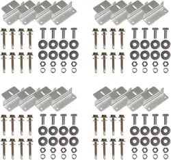
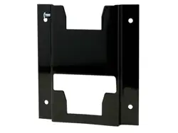
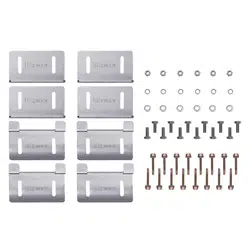
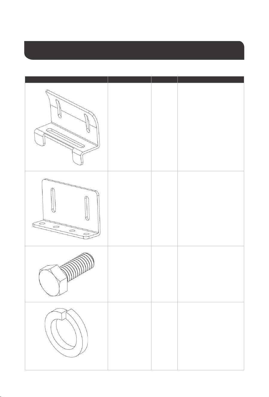
Identification of Parts
Image Component
Curved Bracket
(A)
4
Qty. Description
Main component. Attached to
panel frame using the
included fasteners.
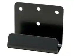
Straight Bracket
(B)
4
Main component. Attached to
the Curved Bracket and
secures panels to mounting
surface using the included
fasteners.
M6 x 16mm Hex
Cap Bolt
(C)
12
Fastener used to attach
Curved Bracket to panel, and
attach Straight Bracket to
Curved Bracket.
Material: Stainless Steel
M6 Split Lock
Washer
(D)
4
Deformable washer which
c
reates a spring force from
deformation. Provides the
necessary pre-load to cap
bolt. Used on cap bolts for
fixing Curved Bracket and
panel together.
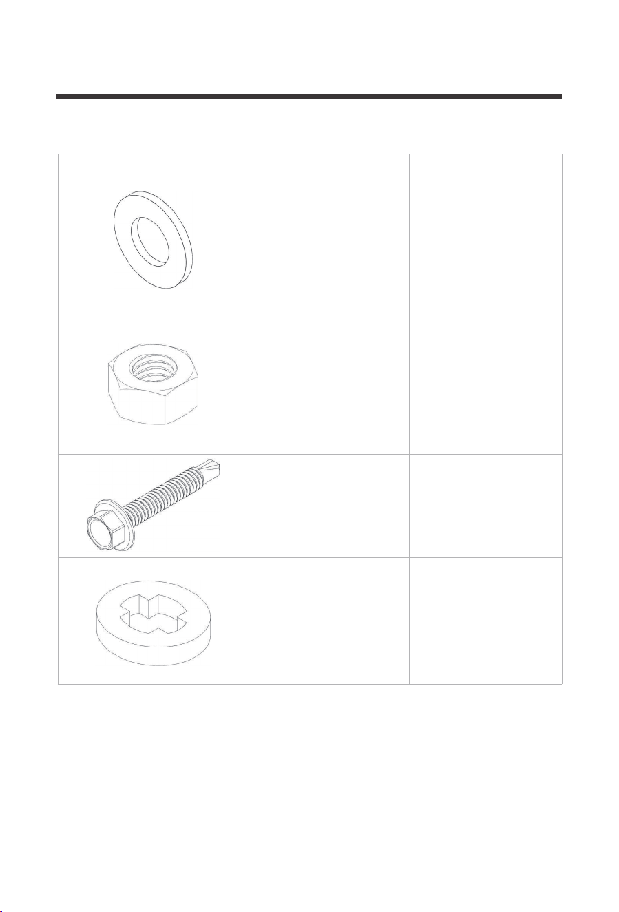
06
M6 Flat Washer
(E)
16
Normal flat washer used to
prevent surface marring on
components from the use of
the Lock Washers and Nuts.
M6 Hexagonal
Nut
(F)
12
Used to tighten down joint
between components and
panel.
#10 x 1¼ in
Self-Drilling Cap
Screw
(G)
16
Screw capable of self-drilling
into the mounting surface.
Used to secure Straight
Bracket to the mounting
surface.
Material: Steel
Plastic Retaining
Ring
(H)
16
Placed between the self�
drilling screws and Straight
Bracket. Should come
threaded over self-drilling
screws in package.
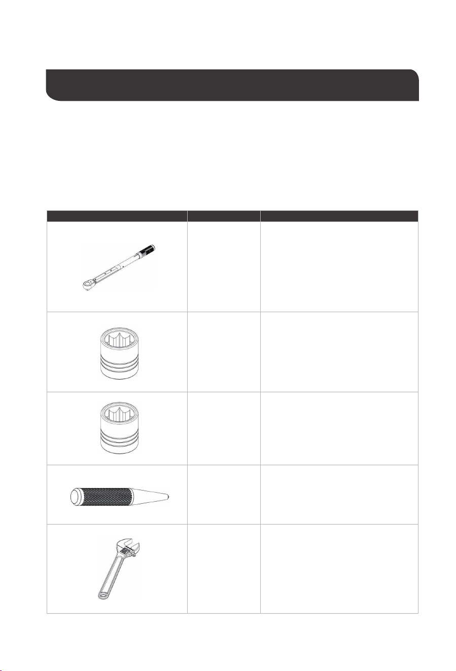
Installation
The following tools and equipment are highly recommended to have available to assist with
installation but are in no way a comprehensive list of tools that can ease installation. Installers
feel free to substitute comparable equipment where appropriate.
Recommended tools to have before installation:
07
Image Composant Description
A
llows for tightening of fasteners.
6mm Socket
Drive
Ratchet Wrench
Used with ratchet to tighten down bolted joint
between panel and bracket.
5/32” Socket
Drive
Used with ratchet to drive screw into mounting
surface and secure bracket to it.
Center Punch
Indents mounting surface to reduce
screw wandering during initial drive.
Crescent
Wrench
Used to prevent rotation of the nut
during joint tightening until split lock
washer has effectively engaged.
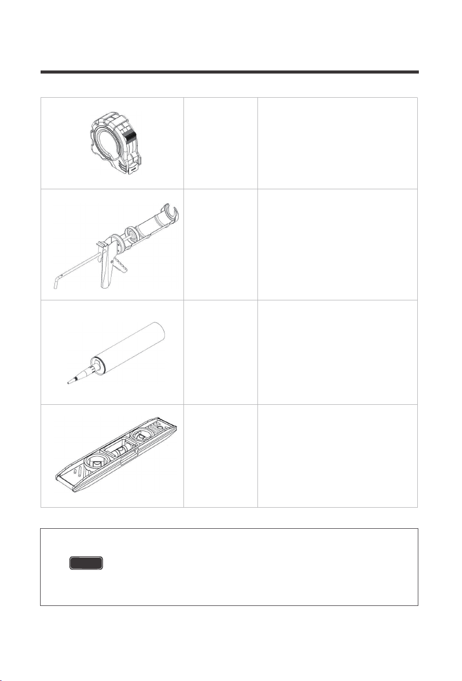
08
Tape Measure
M
ay be useful in planning Bracket
configuration and positioning.
Caulking Gun
Used to direct sealant into
penetrations to avoid leaking
Compatible
Sealant
S
ealant compatible with your specific
installation.
Spirit Level
Used to ensure panel is level and/or plumb to
the mounting surface and orientation.
Installation on shingle roofs is not recommended. System is not
designed with these roof types in mind. Fasteners will not penetrate
framing deep enough and will likely cause heavy issues with leaking.
WARNING
09
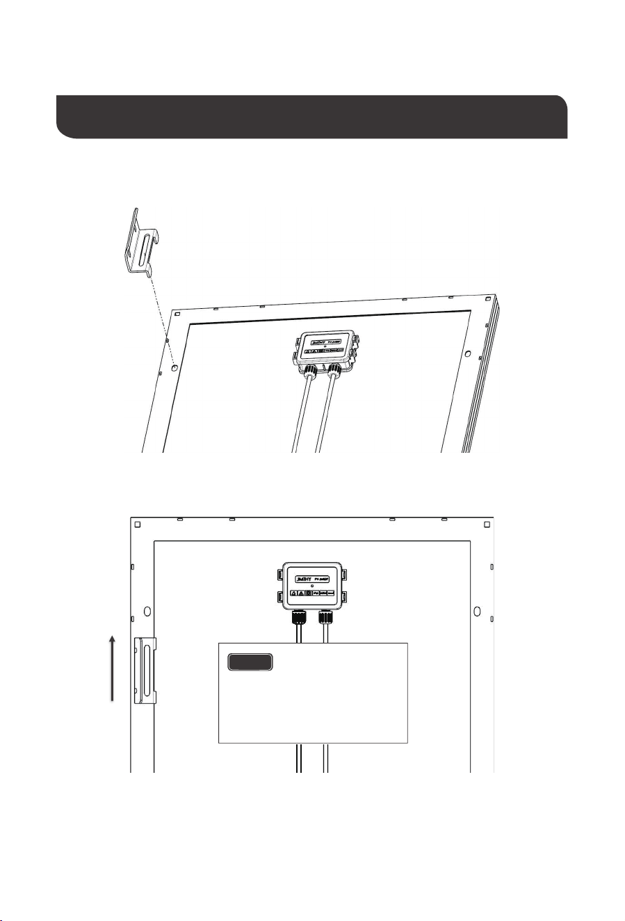
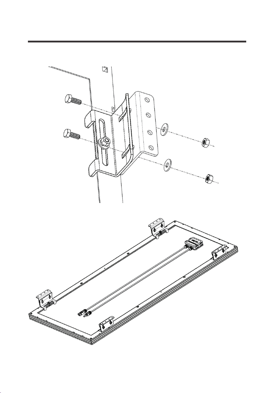
Mating Brackets to Panel Frame
NOTE
Solar modules will
have different varieties of
mounting hole locations. Please
align brackets in a way that will
evenly support the module.
(A)
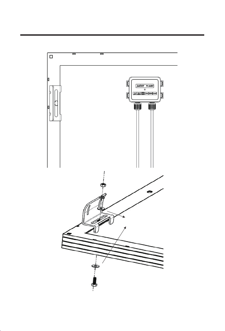
10
(F)
(D)
(C)
(E)
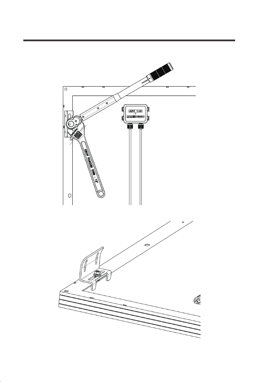
11
12
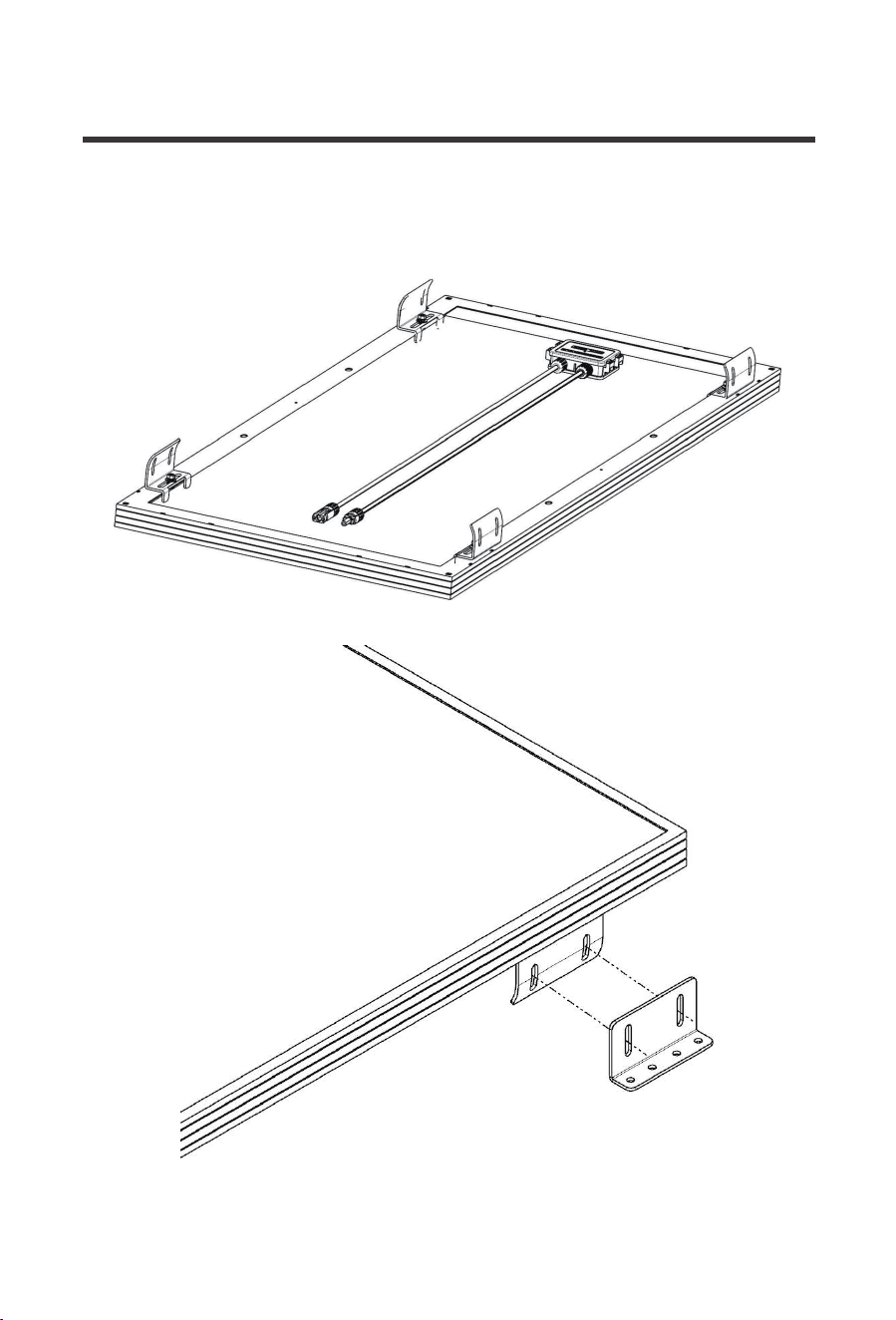
Repeat for each Curved Bracket in the set at each corner.
(B)
13
(C)
(E)
(F)
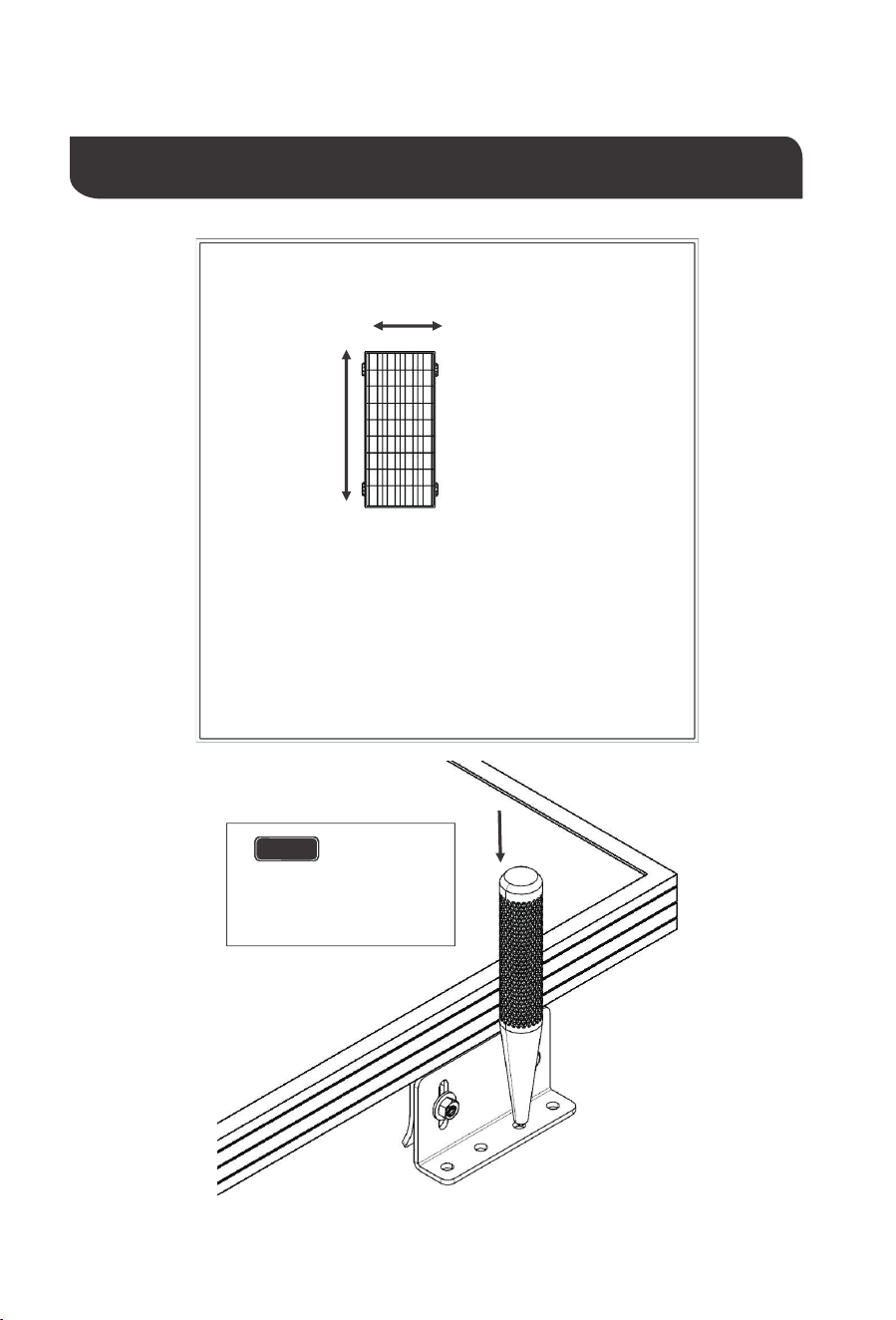
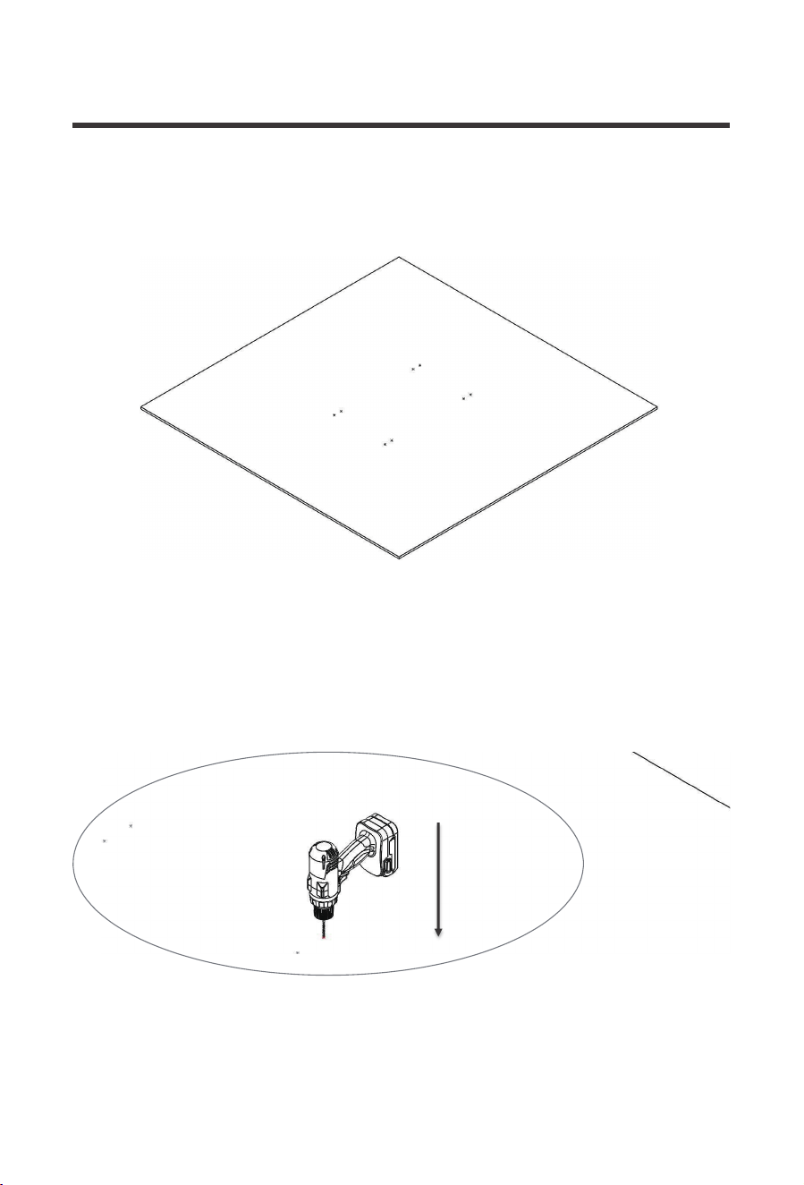
Install Panel to General Flat Mounting Surface
14
NOTE
Ensure screw
surfaces are backed by a
structural element such as
a rafter, stud, etc.
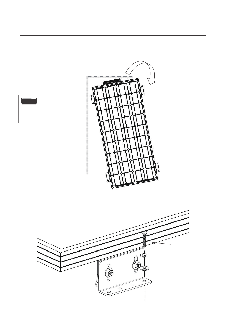
15
(G)
16
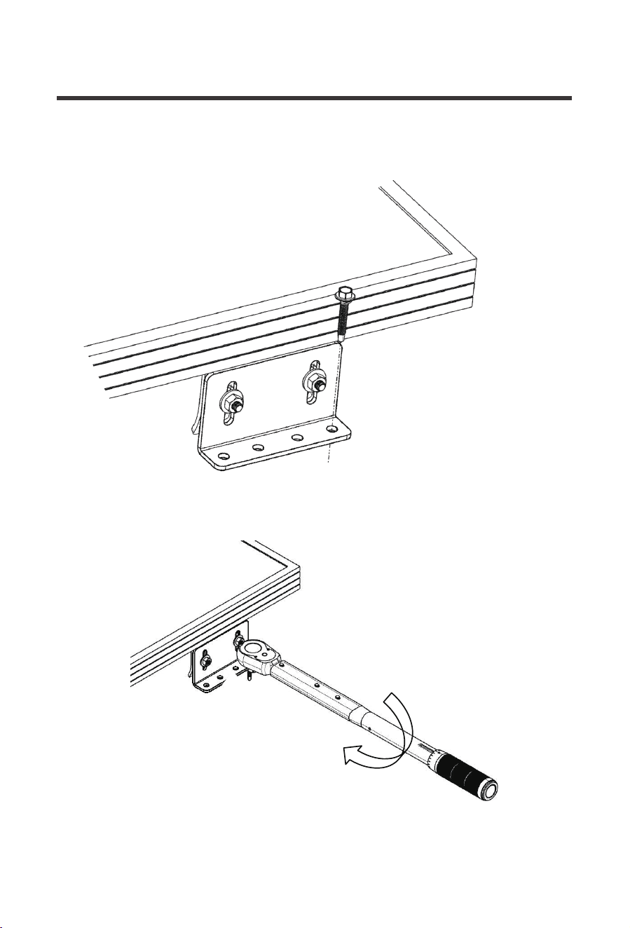
NOTE
Orient panel in
level/plumb layout as desired
before fixing in position.

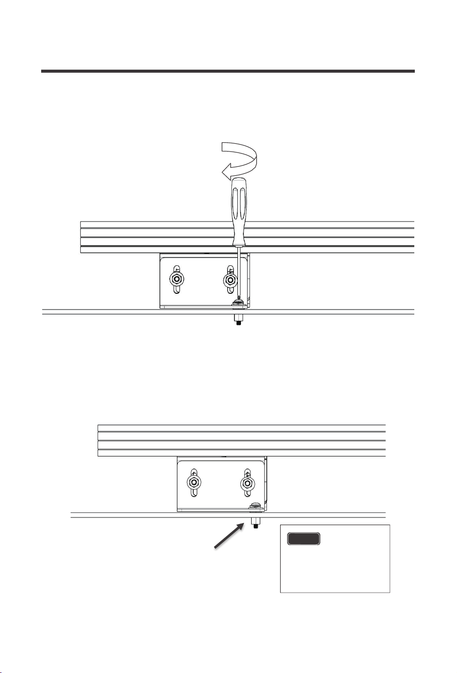
17
Repeat for all fastener locations.
NOTE
Begin new fastener at
indicated location first to secure
panel in level plumb/level layout.
18
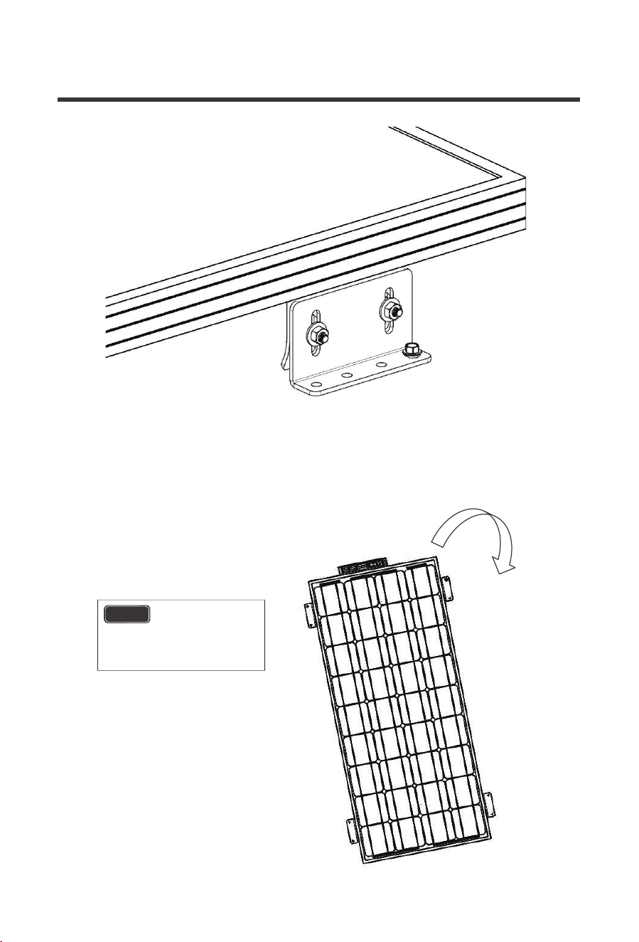
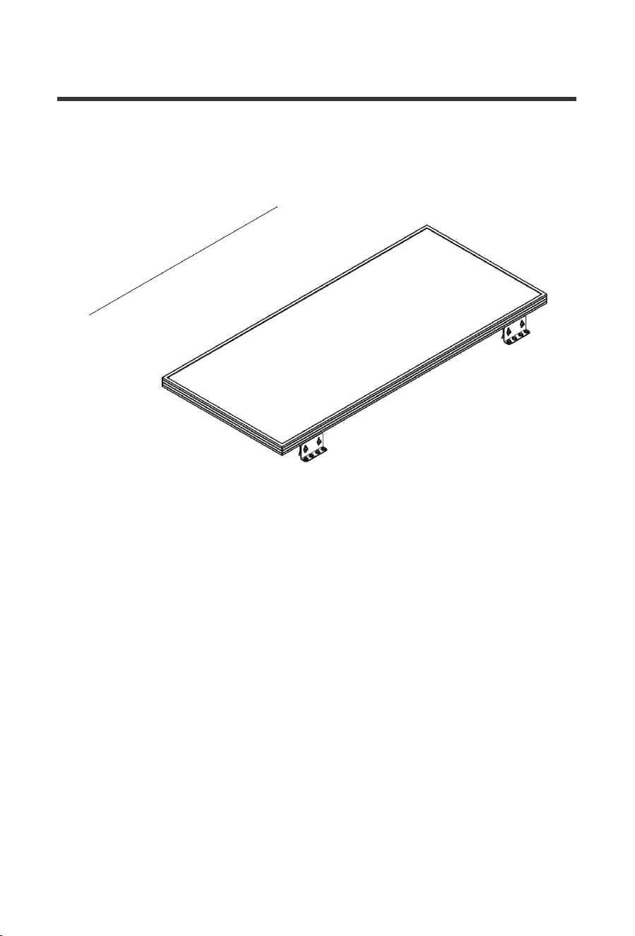
Repeat for all brackets.
NOTE
Seal
around all edges of
bracket and screws.
19
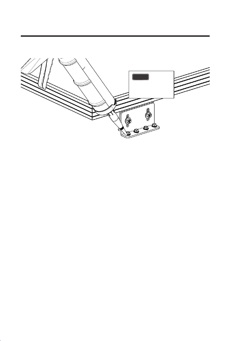
Install Panel to flat RV Roofs
NOTE
Installation on to the roofs of RV’s typically requires more specialized instruction due to the
nature of construction of most commercially available RV roofs. Please note that this section
includes the use of a fastener type NOT included in the Bracket kit. This section is included
for convenience of customers installing to an RV roof. The instructions listed in this section
are a modification of the normal installation, all other steps are to be completed normally.
A minimum roof thickness of 3/8” is recommended for this type of
installation.
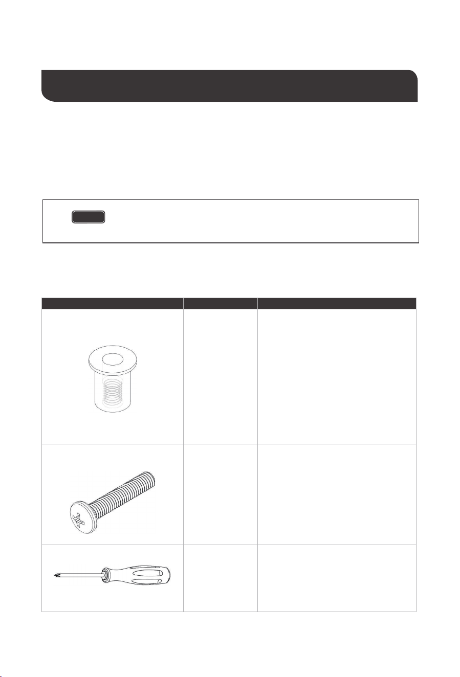
Image Component
Well Nut
(I)
Description
Special recessed fastener which expands
as the internal fastener is tightened. Allows
for fastener to seal within mounting surface
and embed itself tightly. Need variety with
at least #10-32 internal thread, material
thickness supporting roof thickness, and
3/8” hole size. A fastener with suggested
features can be found here:
http://www.mcmaster.com/#93495a190/=xf
p203
http://www.homedepot.com/p/Everbilt-10-
32-tpi-x-5-8-in-Brass-Expansion-Nut-
814358/204276054
Machine
Screw
(J)
Used to secure Brackets to surface with
well nut. Must be compatible with chosen
well nut by having the same internal thread
and not longer than the length of the well
nut. Must also purchase compatible flat
and lock washers.
Phillips
Head Screw
Driver
(K)
Used to secure machine screw into well
nut.
Additional components and tools required for this section:
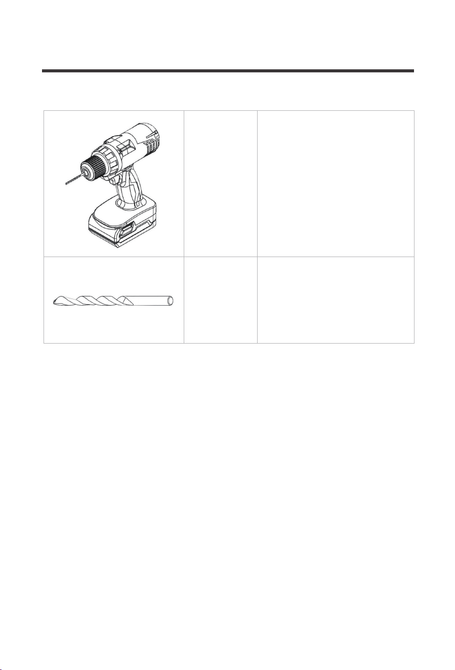
20
Cordless
Drill
Used to drill clearance holes for well nuts
in roof top.
Drill Bit
Used with Cordless Drill to create
clearance holes for the well nuts. Must be
matched to the well nut’s outer diameter.
Recommended variety requires 3/8” bit.
21
NOTE
Mark all hole
locations in this step
as the panel must be
removed for well nut
insertion.
22

23
Repeat for all holes.
(I)
NOTE
Use of sealant
is optional with a well
nut but sealing will add
extra assurance. Seal
under well nut.
24
NOTE
Orient panel in
level/plumb layout as desired
before fixing in position.
(F)
(D)
(J)
25
NOTE
Screw has
compressed and expanded
the well nut, binding into the
roof material.
26
Repeat for all fasteners.
(A)
(B)
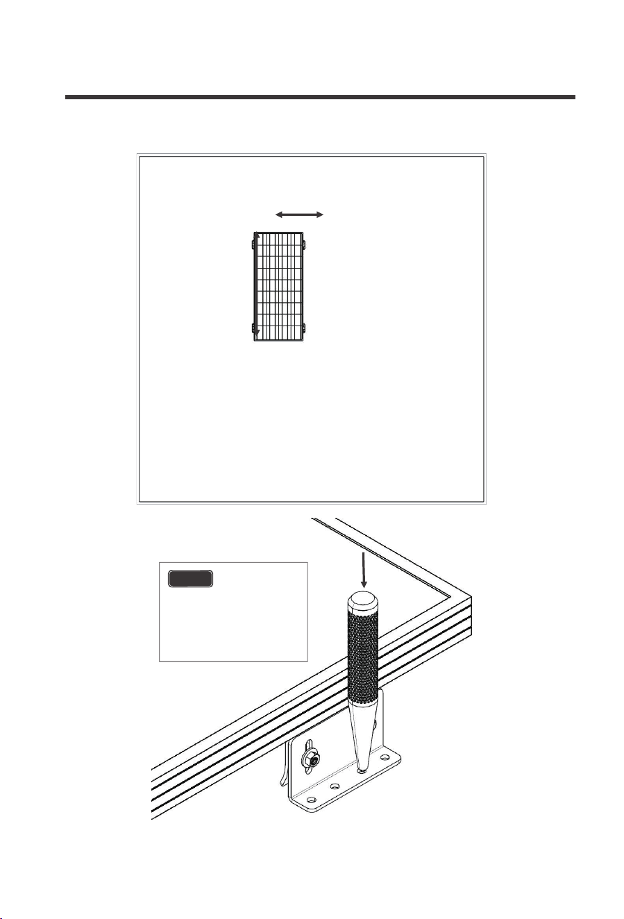
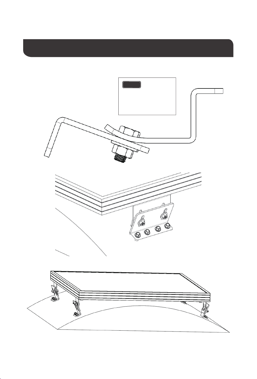
Install Panel to General Mounting Curved Surface
27
NOTE
Adjust the
angle between the two
brackets to match the
curved surface.
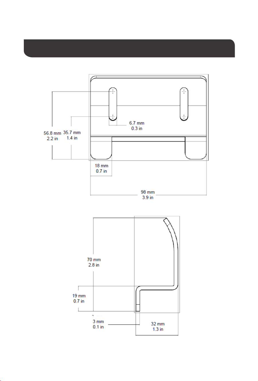
Adjustable Curved Bracket Dimensions
28
29
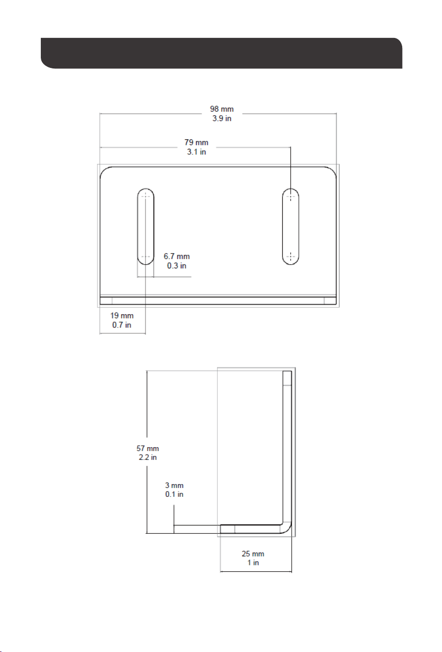
Adjustable Straight Bracket Dimensions

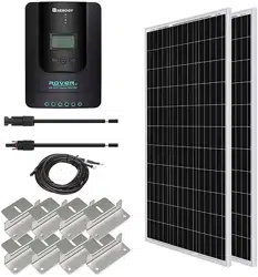
Compatibility
30
RENOGY Solar Module Compatibility*
COMPATIBLE
COMPATIBLE
COMPATIBLE
COMPATIBLE
COMPATIBLE
COMPATIBLE
COMPATIBLE
COMPATIBLE
COMPATIBLE
COMPATIBLE
COMPATIBLE
COMPATIBLE
COMPATIBLE
COMPATIBLE
COMPATIBLE
**
COMPATIBLE
COMPATIBLE
COMPATIBLE
**
**
RNG-10D
RNG-10D-SS
RNG-20D
RNG-30D
RNG-30D-SS
RNG-50D
RNG-50D-SS
RNG-80D-SS
RNG-100D
RNG-100D-S
RNG-100D-SS
RNG-100D-SSP
RNG-100MB
RNG-100D-R
RNG-160D-SS
RNG-300D
RNG-50P
RNG-100P
RNG-160P
RNG-270P
RNG-320P

30
Solar module weight does not exceed 88 lbs (40 kg), or total load per bracket does not
exceed 22 lb (10 kg).
Solar module framing material is an aluminum alloy.
If using a panel oriented such that the distance between Brackets along an edge exceeds
39 in (1 m), it is advisable to add Brackets for mid-span support. Lack of mid-span support
can cause excessive stress in the module under load and can result in solar module
damage. Consult with your solar module manufacturer if you are unsure of the
compatibility.
* This list is not comprehensive and is intended for an “at-a-glance” look at which solar
modules provided by Renogy are compatible with the Bracket Mounting System. Modules
provided by other manufacturers may work with the Bracket Mounting System provided the
following conditions are met:
** These modules require the installation of 2 Bracket sets to ensure the modules do not
excessively flex in their mid-span (a total of 8 pairs of Brackets per module).
Renogy reserves the right to change
the contents of this manual without notice.
RENOGY.COM
US
CN
CA
AU
JP
UK
5050 S Archibald Ave Ontario, CA 91762, USA
909-287-7111
www.renogy.com
support@renogy.com
苏州高新区科技城培源路1号5号楼-4
400-6636-695
https://www.renogy.cn
support@renogy.cn
https://www.renogy.jp
supportjp@renogy.com
https://ca.renogy.com
supportca@renogy.com
https://au.renogy.com
supportau@renogy.com
https://uk.renogy.com
supportuk@renogy.com
https://de.renogy.com
supportde@renogy.com
DE