
INSTALLATION, OPERATION, AND
MAINTENANCE INSTRUCTIONS
HI-E DRY
195
QUESTCLIMATE.COM / (877) 420-1330
Patents: thermastor.com/patents
TS-2118 10/24 REV A
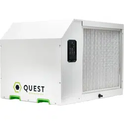
Onboard Digital Controls
Industry-Leading Efficiency
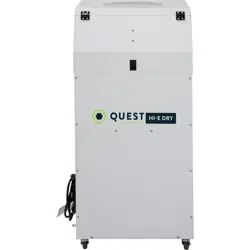
Portable Design with Casters
Internal Condensate Pump
MERV-11 Air Filtration
Model Number #4046400
Serial Number
Install Date
Sold By
CALIFORNIA
TITLE 24 COMPLIANT

2
HI-E DRY 195 INSTALLATION, OPERATION, AND MAINTENANCE INSTRUCTIONS
QUESTCLIMATE.COM(877) 420-1330

3
HI-E DRY 195 INSTALLATION, OPERATION, AND MAINTENANCE INSTRUCTIONS
QUESTCLIMATE.COM(877) 420-1330
TABLE OF CONTENTS
Safety Precautions ...................................................... 4
1. Intended Application ........................................... 5
2. Registrations ........................................................ 5
3. Specifications ....................................................... 5
4. Installation ............................................................ 6
4.1 Location ....................................................... 6
4.2 Electrical Requirements ............................ 7
4.3 Condensate Removal ................................. 7
4.4 Ducting ......................................................... 7
A. Optional Ducting .................................... 7
B. Ducting for Dehumidification .............. 7
C. Ducting for Fresh Air ............................. 7
5. Operation ............................................................... 9
5.1 Humidity Control Adjustment .................. 9
5.2 Fan Mode ON ............................................... 9
5.3 Purge Water ................................................ 9
5.4 Defrost Control ........................................... 9
5.5 Power Down ................................................. 9
6. Maintenance ........................................................ 10
6.1 Air Filter ..................................................... 10
7. Service ................................................................. 10
7.1 Warranty ..................................................... 10
7.2 Technical description ............................... 10
7.3 Service Personnel ..................................... 11
A. Checks to Electrical Devices .............. 11
B. Repairs to Sealed Components........... 12
C. Intrinsically Safe Components............ 12
D. Detection of Flammable Refrigerant...13
E. Refrigerant Removal and Evacuation..13
F. Charging Procedures ............................ 13
7.4 Troubleshooting ......................................... 15
7.5 Refrigerant Charging ................................ 16
7.6 Blower Replacement ................................. 16
7.7 Compressor/Capacitor Replacement ..... 16
A. Check Compressor Motor Circuits...... 16
B. Replace a Burned Out Compressor...... 17
C. Replace a Compressor, Non-BurnOut..18
7.8 Relay ............................................................. 18
7.9 Humidity Control ........................................ 18
7.10 Defrost Thermistor .................................... 18
7.11 Condensate Pump ......................................... 18
8. Wiring Diagram ..................................................... 19
9. Decommissioning ................................................ 20
10. Service Parts List ............................................... 22
11. Accessories .......................................................... 22
Warranty ....................................................................... 24
4201 Lien Rd. Madison, WI 53704 | 1-877-420-1330
THERMASTOR.COM | © 2024 Therma-Stor LLC
4
HI-E DRY 195 INSTALLATION, OPERATION, AND MAINTENANCE INSTRUCTIONS
QUESTCLIMATE.COM(877) 420-1330
SAFETY PRECAUTIONS
Read the installation, operation and maintenance instructions carefully before installing
and operating this device. Proper adherence to these instructions is essential to obtain
maximum benefit from your Quest Hi-E Dry 195.
READ AND SAVE THESE INSTRUCTIONS
» The device is designed to be installed INDOORS IN A SPACE THAT IS PROTECTED
FROM RAIN AND FLOODING.
» Install the unit with space to access the back or side panels for maintenance and
service. DO NOT INSTALL UNIT WITH THE SERVICE PANELS INACCESSIBLE.
» Avoid directing the discharge air at people, or over the water in pool areas.
» If used near a pool, spa, or water: be certain there is NO chance the unit could fall
into the water or be splashed and that it is plugged into an outlet that is a GROUND
FAULT INTERRUPT protected circuit.
» DO NOT use the device as a bench or table.
» DO NOT place the device directly on structural members. Provide vibration isolation
in order to minimize operational vibration and/or noise.
» A drain pan MUST be placed under the unit if installed above a living area or above
an area where water leakage could cause damage.
» Never operate a unit with a damaged power cord. If the power cord is damaged it
must be replaced by the manufacturer, its service agent, or similarly qualified person
in order to avoid a hazard.
» Make all electrical connections in accordance with the current edition of the NEC
ANSI/NFPA 70 and any national and local codes or ordinances that may apply.
» Maintain a minimum 3ft. (1m) clearance to avoid obstructing the air return and
supply.
» This appliance is not intended for use by persons (including children) with reduced
physical, sensory or mental capabilities, or lack of experience and knowledge, unless
they have been given supervision or instruction concerning use of the appliance by
a person responsible for their safety. Children should be supervised to ensure that
they do not play with the appliance.
» Not intended for use at altitudes over 6500 ft (2000M).
Do not use means to accelerate the defrosting process or to clean,
other than those recommended by the manufacturer.
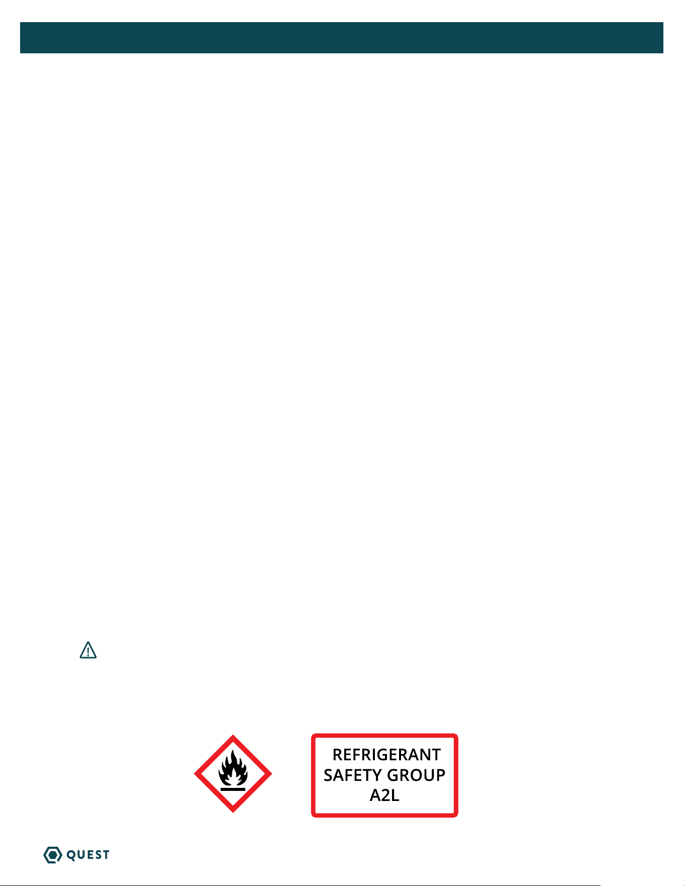
The appliance shall be stored in a room without continuously operating ignition sources
(for example: open flames, an operating gas appliance, or an operating electric heater.
Do not pierce or burn. Be aware that refrigerants may not contain an odor.
WARNING
5
HI-E DRY 195 INSTALLATION, OPERATION, AND MAINTENANCE INSTRUCTIONS
QUESTCLIMATE.COM(877) 420-1330
1. INTENDED APPLICATION FOR QUEST HI-E DRY 195 DEHUMIDIFIER
The Quest Hi-E Dry 195 dehumidifier is designed to operate in temperatures between 56° and 95°F.
In order to efficiently control humidity levels, the area in which the dehumidifier is to be operated must
be free of water intrusion or excessive fresh (outside) air infiltration. Before installing the Quest Hi-E
Dry 195 dehumidifier, water intrusion and air infiltration problems should be addressed or noted in
calculations.
2. REGISTRATIONS
The Quest Hi-E Dry 195 dehumidifier units conform to unified standard UL 60335-2-40, CSA
C22,2#60335-2-40.
US Patents: D570,988 / 8,069,681 / 9,052,132 / 10,458,730 B2 / 10,458,730 B2
3. SPECIFICATIONS @ 80°F/60% RH
UNIT:
Hi-E Dry 195
4046400
BLOWER:
(Tested with duct collars on)
610 CFM @ 0.0" WG
POWER: (WATTS)
1385
SUPPLY VOLTAGE:
110-120 VAC -
1 Phase - 60 Hz.
CURRENT DRAW: (Amps)
12
OPERATING TEMP:
56°F Min - 95°F Max
WATER REMOVAL: (Pints/Day)
EFFICIENCY: (Pints/kWh)
195
7.2
AIR FILTER: (MERV-11 Nominal)
Size: 16" x 20" x 2"
POWER CORD:
DRAIN CONNECTION:
3/4” Threaded NPT
REFRIGERANT TYPE:
REFRIGERANT AMOUNT:
R454B
1 lb. 12oz.
DIMENSIONS:
WIDTH:
HEIGHT:
LENGTH:
WEIGHT:
UNIT SHIPPING
20” 26”
42” 47”
19” 24”
130 lbs 145 lbs
14ga 10’, NEMA 5-20P
*THIS UNIT REQUIRES A
DEDICATED 20A CIRCUIT
Specifications subject to change without notice.

6
HI-E DRY 195 INSTALLATION, OPERATION, AND MAINTENANCE INSTRUCTIONS
QUESTCLIMATE.COM(877) 420-1330
4. INSTALLATION
4.1 LOCATION
The Hi-E Dry 195 can be installed in a variety of locations to meet the owner’s needs as listed below. In
all cases keep the following cautions in mind:
» It is designed to be installed INDOORS ONLY.
» If used near a pool or spa, be certain there is NO chance the unit could roll into the water or be
splashed and that it is plugged into a GROUND FAULT INTERRUPTER.
» Avoid discharging the air directly at people, especially in pool areas.
» A flooded unit is not covered by warranty.
» DO NOT hang the Quest Hi-E Dry 195 from its’ cabinet.
» The minimum floor area of the room shall be 28 m
2
(square meters).
» Keep any required ventilation openings clear of obstruction.
» Ducts connected to the dehumidifier shall not contain a POTENTIAL IGNITION SOURCE.
» Supply and return air shall be directly ducted to the space. Open areas such as false ceilings shall
not be used as a return air duct.
Unventilated Areas
» Unventilated Areas where the Quest Hi-E Dry 195 is installed or stored need to be so constructed
that should any refrigerant leak, it will not stagnate so as to create a fire or explosion hazard.
» Quest Hi-E Dry 195 shall not be stored or ducted into one or multiple rooms with continuously
operating open flames (for example an operating gas appliance) or other POTENTIAL IGNITION
SOURCES (for example an operating electric heater, hot surfaces). A flame-producing device may be
installed in the same space if the device is provided with an effective flame arrest.
4.1A IN HUMID AREA, NO DUCTING
The simplest installation is to place the Hi-E Dry 195 in the humid area with no ducting. The air inlet on
top & outlet on the side must be at least 1’ from walls and other obstructions to air flow.
4.1B IN HUMID AREA, DUCT INLET AND/OR OUTLET
If the humid area is very large or has high ceilings, dehumidification can be improved by adding an inlet
and/or outlet duct to circulate and destratify stagnant areas. For a large area, add inlet or outlet ducting
to create flow across the area’s greatest length.
For areas with ceilings higher than 12’, use an inlet duct to draw warm, moist air from near the ceiling.
See section 2.4 for attaching duct collars & ducting.
4.1C IN REMOTE AREA, DUCT OUTLET ONLY
This works well if there is an adequate air flow path between the two rooms; e.g., high door undercut,
louvered door or wall grill. There are several potential disadvantages to using this method. First, humid
air is drawn into the room where the Hi-E Dry 195 is located. Second, to accurately sense humidity,
the blower in the Hi-E Dry 195 may need to run continuously to draw air from the humid room into the
Hi-E Dry 195 room. Third, a slight negative pressure is created in the room with the Hi-E Dry 195 which
could back draft open combustion devices located there. If such devices are present, call the factory for
specific instructions before using this installation method or consider the option below.

7
HI-E DRY 195 INSTALLATION, OPERATION, AND MAINTENANCE INSTRUCTIONS
QUESTCLIMATE.COM(877) 420-1330
4.1D IN REMOTE AREA, DUCT INLET ONLY
When the Hi-E Dry 195 is located in a room separate from the main area to be dehumidified, it may
be desirable to dehumidify and/or slightly pressurize that room. Pressurization assures that open
combustion devices do not back draft as would be the case if the room was sufficiently de-pressurized.
This can be accomplished by installing a duct from the humid room to the Hi-E Dry 195 inlet and by
allowing the Hi-E Dry 195 to discharge the dehumidified air into the room in which it’s located. An
adequate air flow path must exist between the two rooms for this method to work well.
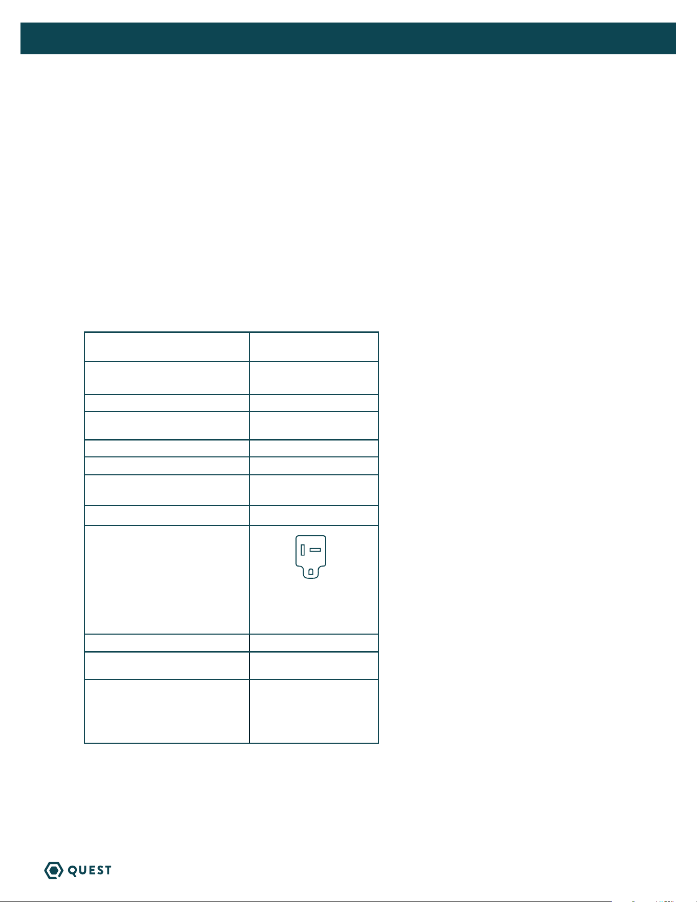
4.2 ELECTRICAL REQUIREMENTS
The Hi-E Dry 195 plugs into a common grounded outlet on a 20-amp circuit. It draws between 3 and 7
amps under normal operating conditions. If used in a wet area (pool, spa room, or basement prone to
flooding), a ground fault interrupter protected circuit is required.
If an extension cord is required, it must have a minimum of 14 gauge conductors if less than 25 feet long
and 12 gauge if greater than 25 feet.
4.3 CONDENSATE REMOVAL
The Hi-E Dry 195 is equipped with an internal condensate pump to remove the water that is condensed
during dehumidification. This allows the condensate to be pumped 30’ with the attached hose. If the
condensate must be pumped more than 17 feet above the unit, a second pump must be added to relay
the condensate. The condensate pump is mounted inside the Hi-E Dry 195 as a permanent, integral part
of the unit. It includes a safety switch feature that prevents flooding by turning off the Hi-E Dry 195 if
the pump fails.
4.4 DUCTING
4.4A OPTIONAL DUCTING
A ducting kit consisting of one 12” Inlet duct collar, one 10” Outlet duct collar and one block off plate is
available from the factory that will allow ducting to be attached to the inlet and outlet of the Hi-E Dry
195. Attach the inlet collar to the top of the unit.
4.4B DUCTING FOR DEHUMIDIFICATION
Ducting the Hi-E Dry 195 requires consideration of the following points:
Duct Sizing: For total duct lengths up to 25’, use a minimum 12” diameter round or equivalent
rectangular for the intake and 10” diameter round or equivalent rectangular for the outlet. Grills or
diffusers on the duct ends must not excessively restrict airflow.
Isolated Areas: Effective dehumidification may require that ducting be branched to isolated, stagnant
areas. Use 8” diameter branch ducting to each of two or three areas; use 6” to each of four or five
areas; use 4” to each of six or more areas.
4.4C DUCTING FOR FRESH AIR
Fresh air can be brought into the structure continuously by connecting a duct from outside to the Hi-E
Dry 195 inlet and by turning on the fan ON mode. Advantages of this form of ventilation include:
1. Outside air is filtered before entering the building.
2. Outside air will be dehumidified before entering if the Hi-E Dry 195 is running.
3. Drawing air from outside and blowing inside aids in pressurizing the structure. This helps prevent
unfiltered and undehumidified air from entering elsewhere. It also reduces the potential for

8
HI-E DRY 195 INSTALLATION, OPERATION, AND MAINTENANCE INSTRUCTIONS
QUESTCLIMATE.COM(877) 420-1330
carcinogenic radon gas to enter.
4. The need for an alternate ventilation device may be eliminated.
An insulated 4” diameter duct is generally sufficient to provide up to 70 CFM of outside air. A 6” duct
with an adjustable damper is recommended for higher flows. Large quantities of outside air will impact
Hi-E Dry 195 performance positively or negatively, depending upon the difference between inside and
outside air conditions. Consult the factory by calling 1-800-533-7533 for recommendations regarding the
use of higher flows with your specific application.
The outside air duct should be connected into the main inlet duct close to the unit. If no other inlet duct
is used, it may be necessary to obstruct the inlet of the Hi-E Dry 195 to ensure adequate ventilation.
5. OPERATION
9
HI-E DRY 195 INSTALLATION, OPERATION, AND MAINTENANCE INSTRUCTIONS
QUESTCLIMATE.COM(877) 420-1330
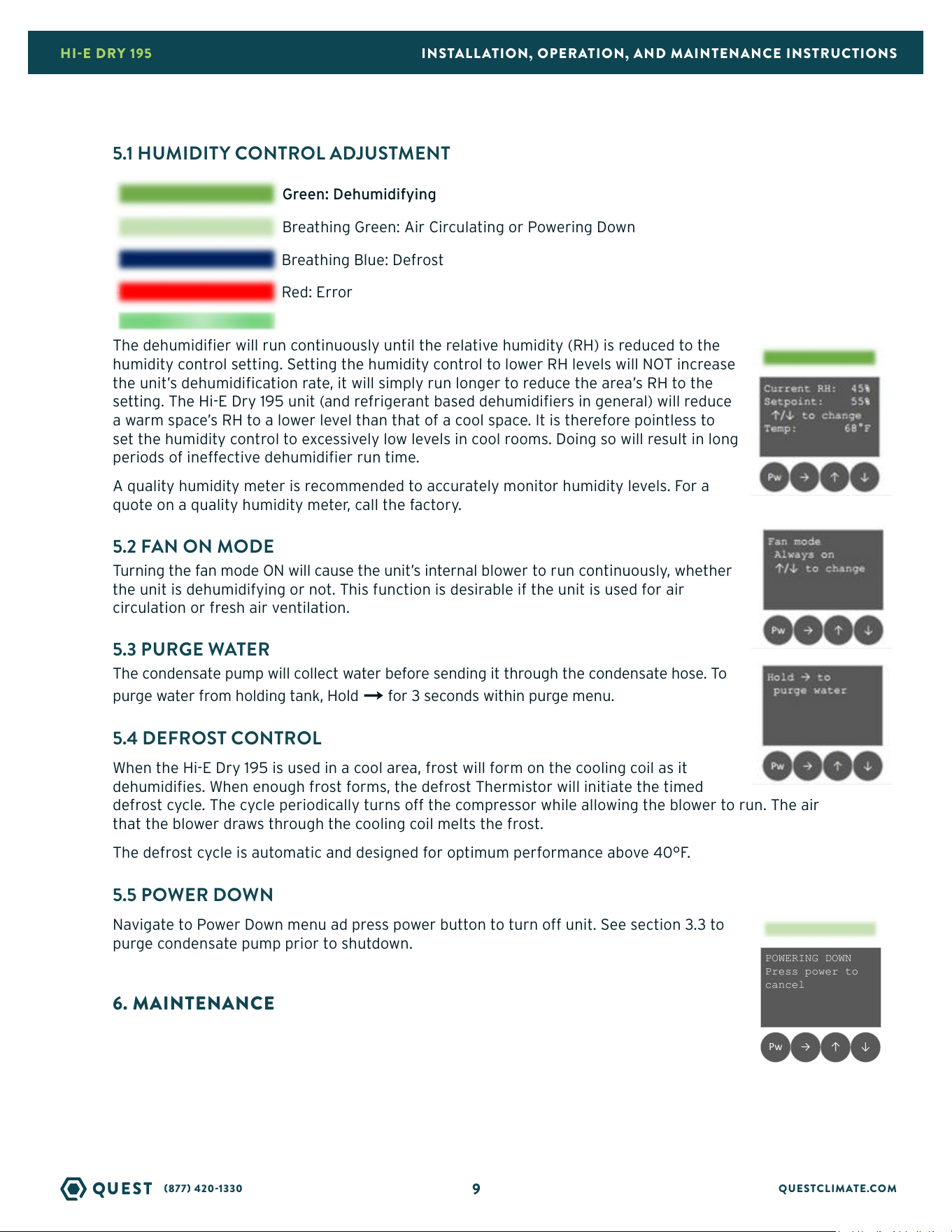
5.1 HUMIDITY CONTROL ADJUSTMENT
The dehumidifier will run continuously until the relative humidity (RH) is reduced to the
humidity control setting. Setting the humidity control to lower RH levels will NOT increase
the unit’s dehumidification rate, it will simply run longer to reduce the area’s RH to the
setting. The Hi-E Dry 195 unit (and refrigerant based dehumidifiers in general) will reduce
a warm space’s RH to a lower level than that of a cool space. It is therefore pointless to
set the humidity control to excessively low levels in cool rooms. Doing so will result in long
periods of ineffective dehumidifier run time.
A quality humidity meter is recommended to accurately monitor humidity levels. For a
quote on a quality humidity meter, call the factory.
5.2 FAN ON MODE
Turning the fan mode ON will cause the unit’s internal blower to run continuously, whether
the unit is dehumidifying or not. This function is desirable if the unit is used for air
circulation or fresh air ventilation.
5.3 PURGE WATER
The condensate pump will collect water before sending it through the condensate hose. To
purge water from holding tank, Hold
→
for 3 seconds within purge menu.
5.4 DEFROST CONTROL
When the Hi-E Dry 195 is used in a cool area, frost will form on the cooling coil as it
dehumidifies. When enough frost forms, the defrost Thermistor will initiate the timed
defrost cycle. The cycle periodically turns off the compressor while allowing the blower to run. The air
that the blower draws through the cooling coil melts the frost.
The defrost cycle is automatic and designed for optimum performance above 40°F.
5.5 POWER DOWN
Navigate to Power Down menu ad press power button to turn off unit. See section 3.3 to
purge condensate pump prior to shutdown.
6. MAINTENANCE
Current RH: 45%
Setpoint: 55%
↑/↓ to change
Temp: 68°F
↓↑→Pw ↓↑→Pw
On Power button pressed,
Turn off backlight and all
dehumidifier functions
Display ambient
Display set point
Control set point with ↑ and ↓
keys
Move to temperature unit screen
with →
Current RH: 45%
Setpoint: 55%
↑/↓ to change
Temp: 68°F
↓↑→Pw
Hold → to
purge water
↓↑→Pw
Display fan mode (always on or
auto)
Change with ↑ or ↓ keys
Move to color bar screen with →
Display error
Red color bar
ERROR FLOOD
Check hose
↓↑→Pw
Dehu: green
Circulate: breathing green
Powering down: breathing green
User adjusts setpoint: no change
Defrost: breathing blue
Dehumidistat: off (breathing
green if fan always on)
Error: red
Identify: flashing purple and
orange
Fan mode
Always on
↑/↓ to change
↓↑→Pw
Hold → for 3 seconds to purge
Move to fan screen with →
Display error
Red color bar
Dehumidifier/Defrost cycle runs at
maximum
SENSOR ERROR
Could not read
humidity
↓↑→Pw
Display ambient RH
Display set point
Dim color bar, if on
Ignore next key press and go to
normal screen
Current RH: 45%
Setpoint: 55%
Press any key
→Pw
Limp mode?
POWERING DOWN
Press power to
cancel
↓↑→Pw
If compressor has turned on since
dehumidifier was turned on, turn
on fan for 3 minutes before
powering off
Current RH: 55%
Setpoint: 45%
Temp too low
Temp: 38°F
↓↑→Pw
Display ambient
Display set point
Move to temperature unit screen
with →
Temp: 68°F
↑/↓
for °C
→Pw
Display ambient temperature
↑/↓
to change units
Move to fan screen with
Display error
Red color bar
Dehumidifier does not run for an
hour
SYSTEM PAUSED
Refrigerant low
↓↑→Pw
Green: Dehumidifying
Breathing Green: Air Circulating or Powering Down
Breathing Blue: Defrost
Red: Error
Pinging Green: Fan auto and setpoint reached
10
HI-E DRY 195 INSTALLATION, OPERATION, AND MAINTENANCE INSTRUCTIONS
QUESTCLIMATE.COM(877) 420-1330
6.1 AIR FILTER
The Hi-E Dry 195 is equipped with a 2” thick, MERV 11 pleated fabric air filter that must be checked
regularly. Operating the unit with a dirty filter will reduce the dehumidifier’s capacity and efficiency and
may cause the compressor to cycle off and on unnecessarily on the defrost control.
Replacement filters can be ordered from the factory or purchased locally if available. DO NOT operate
the unit without the filter or with a less effective filter as the heat exchange coils inside the unit could
become clogged and require disassembly to clean.
7. SERVICE
CAUTION: Servicing the Hi-E Dry 195 with its high-pressure refrigerant system and high
voltage circuitry presents a health hazard which could result in death, serious bodily
injury, and/or property damage. Only qualified service people should service this unit.
Navigate to diagnostic menu and hold
→
to view alerts.
7.1 WARRANTY
A warranty certificate has been enclosed with this unit. Read it before any repair is initiated. If a
warranty repair is required, call the factory first at 1-800-533-7533 for warranty claim authorization and
technical assistance.
7.2 TECHNICAL DESCRIPTION
Refer to Figure 3. The Hi-E Dry 195 uses a
refrigeration system similar to an air conditioner’s to
remove heat and moisture from incoming air, and add
heat to the
air that is discharged.
Hot, high-pressure refrigerant gas is routed from the
compressor to the condenser coil. The refrigerant
is cooled and condensed by giving up its heat to the
air that is about to be discharged from the unit. The
refrigerant liquid then passes through two capillary
tubes, which cause the refrigerant pressure and
temperature to drop. It next enters the evaporator
coil where it absorbs heat from the incoming air and
evaporates.
The evaporator operates in a flooded condition, which
means that it should always be full of liquid refrigerant
during normal operation. A flooded evaporator should
maintain constant pressure and temperature across the
entire coil, from inlet to outlet.
The mixture of gas and liquid refrigerant enter the accumulator after leaving the evaporator coil. The
accumulator prevents any liquid refrigerant from reaching the compressor. The compressor evacuates
the cool refrigerant gas from the accumulator and compresses it to a high pressure and temperature to
repeat the process.
Figure 3: Refrigeration system of Hi-E Dry 195
DIAGNOSTIC MODE
3 alerts
↑/↓ to scroll
Hold → to test
↓↑→Pw
Show alerts if there are any, active
and then recent alerts shown first
Scroll with
↑/↓
Move to main screen with →
Hold → for 3 seconds to run
diagnostic tests
Display ambient RH
Display set point
Dim color bar, if on
Ignore next key press and go to
normal screen
Current RH: 45%
Setpoint: 55%
Press any key
↓↑→
Pw
PRODUCTION TEST
→ Func Test
↑ Refrig. test
↓↑→Pw
Production test
Functional test: verify
functionality of buttons, color bar,
sensors, fan, compressor, pump
Refrigeration test: timer starts and
if the coil is 15 degrees less than
ambient, the test passes
Display LED color bar setting (on
or off)
Change with ↑ or ↓ keys
Move to diagnostics screen with
→
Color bar
On
↑/↓ to change
↓↑→Pw
DEHU ID
3d84732a5470
FIRMWARE VERSION
0.0.1
↓↑→Pw
Color bar flashes blue and orange
Dehu ID and firmware version
displayed on LCD screen
Move to main screen with → or to 1
minute no touch screen after a
minute
Temp: 68°F
↑/↓
for °C
↓↑→
Pw
Display ambient temperature
↑/↓
to change units
Move to fan screen with
→

11
HI-E DRY 195 INSTALLATION, OPERATION, AND MAINTENANCE INSTRUCTIONS
QUESTCLIMATE.COM(877) 420-1330
7.3 SERVICE PERSONNEL
Only qualified HVAC or electrical contractors are allowed to conduct maintenance, service and/or repair
operations on Quest Hi-E Dry 195 machines. Examples include but are not limited to breaking into the
REFRIGERATION circuit, opening of sealed components, and/or opening of ventilated enclosures.
Prior to beginning work on the Quest Hi-E Dry 195 machine, safety checks are necessary to ensure that
the risk of ignition is minimized.
» For repair to the REFRIGERATION SYSTEM, a qualified contractor should first establish a controlled
procedure so as to minimize the risk of a flammable gas or vapor being present while the work is being
performed
» All maintenance staff and others working in the local area shall be instructed on the nature of work
being carried out. Work in confined spaces shall be avoided.
» The area shall be checked with an appropriate refrigerant detector prior to and during work, to ensure
the technician is aware of potentially toxic or flammable atmospheres. Ensure that the leak detection
equipment being used is suitable for use with all applicable refrigerants, i.e. non-sparking, adequately
sealed or intrinsically safe.
» If any hot work is to be conducted on the refrigeration equipment or any associated parts, appropriate
fire extinguishing equipment shall be available to hand. Have a dry powder or CO2 fire extinguisher
adjacent to the charging area.
» No person carrying out work in relation to a REFRIGERATION SYSTEM which involves exposing
any pipe work shall use any sources of ignition in such a manner that it may lead to the risk of fire
or explosion. All possible ignition sources, including cigarette smoking, should be kept sufficiently
far away from the site of installation, repairing, removing and disposal, during which refrigerant
can possibly be released to the surrounding space. Prior to work taking place, the area around the
equipment is to be surveyed to make sure that there are no flammable hazards or ignition risks. “No
Smoking” signs shall be displayed.
» Ensure that the area is in the open or that it is adequately ventilated before breaking into the system
or conducting any hot work. A degree of ventilation shall continue during the period that the work
is carried out. The ventilation should safely disperse any released refrigerant and preferably expel it
externally into the atmosphere.
The following checks shall be applied to installations using flammable refrigerants:
» Where electrical components are being changed, they shall be fit for the purpose and to
the correct specification. At all times Therma-Stor’s maintenance and service guidelines
shall be followed. If in doubt, consult Therma-Stor’s technical department for assistance.
» The actual REFRIGERANT CHARGE is in accordance with the room size within which the
refrigerant containing parts are installed;
» The ventilation machinery and outlets are operating adequately and are not obstructed;
» Marking to the equipment continues to be visible and legible. Markings and signs that are
illegible shall be corrected;
» Dehumidifiers are installed in a position where they are unlikely to be exposed to any
substance which may corrode refrigerant containing components, unless the components
are constructed of materials which are inherently resistant to being corroded or are
suitably protected against being so corroded.

12
HI-E DRY 195 INSTALLATION, OPERATION, AND MAINTENANCE INSTRUCTIONS
QUESTCLIMATE.COM(877) 420-1330
7.3A CHECKS TO ELECTRICAL DEVICES
Repair and maintenance to electrical components shall include initial safety checks and
component inspection procedures. If a fault exists that could compromise safety, then no
electrical supply shall be connected to the circuit until it is satisfactorily dealt with. If the
fault cannot be corrected immediately but it is necessary to continue operation, an adequate
temporary solution shall be used. This shall be reported to the owner of the equipment so all
parties are advised.
Initial safety checks shall include:
» that capacitors are discharged: this shall be done in a safe manner to avoid
possibility of sparking;
» that no live electrical components and wiring are exposed while charging,
recovering or purging the system;
» that there is continuity of earth bonding.
7.3B REPAIRS TO SEALED COMPONENTS
» During repairs to sealed components, all electrical supplies shall be disconnected
from the equipment being worked upon prior to any removal of sealed covers,
etc. If it is absolutely necessary to have an electrical supply to equipment during
servicing, then a permanently operating form of leak detection shall be located at
the most critical point to warn of a potentially hazardous situation.
» Particular attention shall be paid to the following to ensure that by working on
electrical components, the casing is not altered in such a way that the level of
protection is affected. This shall include damage to cables, excessive number
of connections, terminals not made to original specification, damage to seals,
incorrect fitting of glands, etc.
» Ensure that the equipment is mounted securely.
» Ensure that seals or sealing materials have not degraded to the point that they no
longer serve the purpose of preventing the ingress of flammable atmospheres
» Replacement parts shall be in accordance with Therma-Stor specifications.
7.3C REPAIRS TO INTRINSICALLY SAFE COMPONENTS
» Do not apply any permanent inductive or capacitance loads to the circuit without
ensuring that this will not exceed the permissible voltage and current permitted for
the equipment in use.
» Intrinsically safe components are the only types that can be worked on while live in
the presence of a flammable atmosphere. The test apparatus shall be at the correct
rating.
» Replace components only with parts specified by Therma-Stor. Other parts may
result in the ignition of refrigerant in the atmosphere from a leak.
CONTINUES ON NEXT PAGE

13
HI-E DRY 195 INSTALLATION, OPERATION, AND MAINTENANCE INSTRUCTIONS
QUESTCLIMATE.COM(877) 420-1330
» NOTE The use of silicon sealant can inhibit the effectiveness of some types of leak
detection equipment. Intrinsically safe components do not have to be isolated prior
to working on them.
» Check that cabling will not be subject to wear, corrosion, excessive pressure,
vibration, sharp edges or any other adverse environmental effects. The check shall
also take into account the effects of aging or continual vibration from sources such
as compressors or fans.
7.3D DETECTION OF FLAMMABLE REFRIGERANTS
Under no circumstances shall potential sources of ignition be used in the searching for or
detection of refrigerant leaks. A halide torch (or any other detector using a naked flame) shall
not be used.
The following leak detection methods are deemed acceptable for all refrigerant systems.
• Electronic leak detectors may be used to detect refrigerant leaks but, in the case of FLAMMABLE
REFRIGERANTS, the sensitivity may not be adequate, or may need re-calibration. (Detection
equipment shall be calibrated in a refrigerant-free area.) Ensure that the detector is not a potential
source of ignition and is suitable for the refrigerant used. Leak detection equipment shall be set at
25% LFL of the refrigerant and shall be calibrated to 454B.
• Leak detection fluids are also suitable for use with most refrigerants but the use of detergents
containing chlorine shall be avoided as the chlorine may react with the refrigerant and corrode the
copper pipe.
• NOTE: Examples of leak detection fluids are:
» bubble method
» fluorescent method agents.
» If a leak is suspected, all open flames shall be removed/extinguished.
If a leakage of refrigerant is found which requires brazing, all of the refrigerant shall be recovered
from the system, or isolated (by means of shut off valves) in a part of the system remote from the leak.
Removal of refrigerant shall be according to Clause DD.9 of 60335-2-40.
7.3E REFRIGERANT REMOVAL AND EVACUATION
When breaking into the refrigerant circuit to make repairs – or for any other purpose – conventional
procedures shall be used. However, for FLAMMABLE REFRIGERANTS it is important that best practice is
followed since flammability is a consideration. The following procedure shall be adhered to:
» remove refrigerant;
» purge the circuit with inert gas (optional for A2L);
» evacuate (optional for A2L);
» purge with inert gas (optional for A2L);
» open the circuit by cutting or brazing.
» The REFRIGERANT CHARGE shall be recovered into the correct recovery cylinders.
Compressed air or oxygen shall not be used for purging refrigerant systems.
» Ensure that the outlet for the vacuum pump is not close to any POTENTIAL
IGNITION SOURCES and that ventilation is available.

14
HI-E DRY 195 INSTALLATION, OPERATION, AND MAINTENANCE INSTRUCTIONS
QUESTCLIMATE.COM(877) 420-1330
7.3F CHARGING PROCEDURES
In addition to conventional charging procedures, the following requirements shall be followed:
• Ensure that contamination of different refrigerants does not occur when using charging equipment.
Hoses or lines shall be as short as possible to minimize the amount of refrigerant contained in them.
• Cylinders shall be kept in an appropriate position according to the instructions.
• Ensure that the REFRIGERATION SYSTEM is grounded prior to charging the system with refrigerant.
• Label the system when charging is complete (if not already).
• Extreme care shall be taken not to overfill the REFRIGERATION SYSTEM.
• Prior to recharging the system, it shall be pressure-tested with the appropriate purging gas. The
system shall be leak-tested on completion of charging but prior to commissioning. A follow up leak
test shall be carried out prior to leaving the site.

15
HI-E DRY 195 INSTALLATION, OPERATION, AND MAINTENANCE INSTRUCTIONS
QUESTCLIMATE.COM(877) 420-1330
7.4 TROUBLESHOOTING
No dehumidification, neither blower nor compressor run.
1. Unit unplugged or no power to outlet.
2. Humidity control set too high or defective (Sec. 5.1 & 7.8)
3. Loose connection in internal wiring.
Some dehumidification, blower runs continuously but compressor only runs sporadically.
1. Unit is in defrost cycle (Sec. 5.4).
2. Loose connection in compressor circuit.
3. Defective compressor overload (Sec. 7.7).
4. Defective compressor (Sec. 7.7).
5. Defective relay (Sec. 7.8).
6. Defrost thermistor defective or loose (Sec. 7.1).
No dehumidification. Blower runs but compressor does not run.
1. Bad connection in compressor circuit.
2. Defective compressor capacitor (Sec. 7.7).
3. Defective compressor overload (Sec. 7.7).
4. Defective compressor (Sec. 7.7).
5. Defective relay or power board/control board (Sec. 7.8).
6. Bad connection in pump circuit.
Blower does not run. Compressor runs briefly but cycles on & off.
1. Loose connection in blower circuit (Sec. 8).
2. Obstruction prevents impeller rotation.
3. Defective blower (Sec. 7.6).
Unit removes some water but not as much as expected.
1. Air temperature and/or humidity have dropped.
2. Humidity meter and/or thermometer used are out of calibration.
3. Unit has entered defrost cycle (Sec. 5.4 & 7.10).
4. Air filter dirty (Sec. 6.1).
5. Defective defrost thermistor (Sec. 10).
6. Low refrigerant charge (Sec. 7.5).
7. Air leak such as loose cover.
8. Defective compressor (Sec. 7.7).
9. Restrictive ducting (Sec. 4.4).
Pump does not pump water.
1. Hose kinked or plugged.
2. Pump check valve plugged (Sec. 7.11).
3. Bad connection in pump circuit.
4. Hose disconnected internally.
Current RH: 45%
Setpoint: 55%
↑/↓ to change
Temp: 68°F
↓↑→Pw ↓↑→Pw
On Power button pressed,
Turn off backlight and all
dehumidifier functions
Display ambient
Display set point
Control set point with ↑ and ↓
keys
Move to temperature unit screen
with →
Current RH: 45%
Setpoint: 55%
↑/↓ to change
Temp: 68°F
↓↑→Pw
Hold → to
purge water
↓↑→Pw
Display fan mode (always on or
auto)
Change with ↑ or ↓ keys
Move to color bar screen with →
Display error
Red color bar
ERROR FLOOD
Check hose
↓↑→Pw
Dehu: green
Circulate: breathing green
Powering down: breathing green
User adjusts setpoint: no change
Defrost: breathing blue
Dehumidistat: off (breathing
green if fan always on)
Error: red
Identify: flashing purple and
orange
Fan mode
Always on
↑/↓ to change
↓↑→Pw
Hold → for 3 seconds to purge
Move to fan screen with →
Display error
Red color bar
Dehumidifier/Defrost cycle runs at
maximum
SENSOR ERROR
Could not read
humidity
↓↑→Pw
Display ambient RH
Display set point
Dim color bar, if on
Ignore next key press and go to
normal screen
Current RH: 45%
Setpoint: 55%
Press any key
→Pw
Limp mode?
POWERING DOWN
Press power to
cancel
↓↑→Pw
If compressor has turned on since
dehumidifier was turned on, turn
on fan for 3 minutes before
powering off
Current RH: 55%
Setpoint: 45%
Temp too low
Temp: 38°F
↓↑→Pw
Display ambient
Display set point
Move to temperature unit screen
with →
Temp: 68°F
↑/↓
for °C
→Pw
Display ambient temperature
↑/↓
to change units
Move to fan screen with
Display error
Red color bar
Dehumidifier does not run for an
hour
SYSTEM PAUSED
Refrigerant low
↓↑→Pw

16
HI-E DRY 195 INSTALLATION, OPERATION, AND MAINTENANCE INSTRUCTIONS
QUESTCLIMATE.COM(877) 420-1330
Evaporator coil frosted continuously, low dehumidifying capacity.
1. Low refrigerant charge (Sec. 7.5).
2. Dirty air filters or airflow restricted. (Sec. 6.1).
3. Defrost thermistor defective (Sec. 7.10).
7.5 REFRIGERANT CHARGING
If the refrigerant charge is lost due to service or a leak, a new charge must be accurately
weighed in. If any of the old charge is left in the system, it must be removed before weighing
in the new charge. Refer to the unit nameplate for the correct charge weight and refrigerant
type. Add the refrigerant through the low side service port.
7.6 BLOWER REPLACEMENT
The centrifugal blower has a PSC motor and internal thermal overload protection. If defective, the
complete assembly must be replaced.
1. Unplug the power cord.
2. Remove the cabinet front.
3. If an outlet duct is connected to the unit, remove it.
4. Disconnect the blower leads.
5. Remove the electrical box.
6. Remove impeller bracket and impeller
7. Reassembling with the new blower is the above procedure reversed.
7.7 COMPRESSOR/CAPACITOR REPLACEMENT
This compressor is equipped with a two terminal external overload, run capacitor, but no start capacitor
or relay.
CAUTION! ELECTRICAL SHOCK HAZARD: ELECTRICAL POWER MUST BE PRESENT TO
PERFORM SOME TESTS; THESE TESTS SHOULD BE PERFORMED BY A QUALIFIED SERVICE PERSON.
7.7A CHECKING COMPRESSOR MOTOR CIRCUITS
Perform the following tests if the blower runs but the compressor does not with the humidity control
ON.
1. Turn the humidity control OFF and unplug the unit, remove the cabinet front.
2. Plug in the unit and turn the humidity control ON. Use a voltmeter to check for 110 to 120 volts
between (a) the relay terminal that the black wire from the compressor connects to and (b) the
capacitor terminal with the (2) white wires, (1) red wire & (1) brown wire connected. If voltage is
present, go to step 3. If no voltage, the relay or the condensate pump safety switch is open or
there is a loose connection in the compressor circuit. Test each component for continuity; see the
appropriate section if a defect is suspected
3. Turn the humidity control OFF and unplug the unit, then disconnect the red and yellow wires from
compressor terminals R & S. Using an ohmmeter check continuity between the points listed below.
4. Compressor terminals C and S: No continuity indicates an open start winding; the compressor must
be replaced.
5. Compressor terminals C and R: No continuity indicates an open run winding; the compressor must be
Current RH: 45%
Setpoint: 55%
↑/↓ to change
Temp: 68°F
↓↑→Pw ↓↑→Pw
On Power button pressed,
Turn off backlight and all
dehumidifier functions
Display ambient
Display set point
Control set point with ↑ and ↓
keys
Move to temperature unit screen
with →
Current RH: 45%
Setpoint: 55%
↑/↓ to change
Temp: 68°F
↓↑→Pw
Hold → to
purge water
↓↑→Pw
Display fan mode (always on or
auto)
Change with ↑ or ↓ keys
Move to color bar screen with →
Display error
Red color bar
ERROR FLOOD
Check hose
↓↑→Pw
Dehu: green
Circulate: breathing green
Powering down: breathing green
User adjusts setpoint: no change
Defrost: breathing blue
Dehumidistat: off (breathing
green if fan always on)
Error: red
Identify: flashing purple and
orange
Fan mode
Always on
↑/↓ to change
↓↑→Pw
Hold → for 3 seconds to purge
Move to fan screen with →
Display error
Red color bar
Dehumidifier/Defrost cycle runs at
maximum
SENSOR ERROR
Could not read
humidity
↓↑→Pw
Display ambient RH
Display set point
Dim color bar, if on
Ignore next key press and go to
normal screen
Current RH: 45%
Setpoint: 55%
Press any key
→Pw
Limp mode?
POWERING DOWN
Press power to
cancel
↓↑→Pw
If compressor has turned on since
dehumidifier was turned on, turn
on fan for 3 minutes before
powering off
Current RH: 55%
Setpoint: 45%
Temp too low
Temp: 38°F
↓↑→Pw
Display ambient
Display set point
Move to temperature unit screen
with →
Temp: 68°F
↑/↓
for °C
→Pw
Display ambient temperature
↑/↓
to change units
Move to fan screen with
Display error
Red color bar
Dehumidifier does not run for an
hour
SYSTEM PAUSED
Refrigerant low
↓↑→Pw

17
HI-E DRY 195 INSTALLATION, OPERATION, AND MAINTENANCE INSTRUCTIONS
QUESTCLIMATE.COM(877) 420-1330
replaced.
6. Compressor terminal C and overload terminal 1: No continuity indicates a defective overload lead.
7. Overload terminals 1 and 3: If there is no continuity, the overload may be tripped; wait 10 minutes and
try again. If there is still no continuity, it is defective and must be replaced.
8. Compressor terminal C and compressor case: Continuity indicates a grounded motor; the compressor
must be replaced.
9. Disconnect the wires from the capacitor. Set the ohmmeter to the Rx1 scale; the capacitor is shorted
and must be replaced if continuity exists across its terminals. If there is no needle movement with the
meter set on the Rx100000 scale, the capacitor is open and must be replaced.
10. Reconnect the wires to the compressor and capacitor; plug in and turn on the unit. If the compressor
fails to start, replace the run capacitor.
7.7B REPLACING A BURNED OUT COMPRESSOR
The refrigerant and oil mixture in a compressor is chemically very stable under normal operating
conditions. However, when an electrical short occurs in the compressor motor, the resulting high
temperature arc causes a portion of the refrigerant oil mixture to break down into carbonaceous sludge,
a very corrosive acid, and water. These contaminants must be carefully removed otherwise even small
residues will attack replacement compressor motors and cause failures.
The following procedure is effective only if the system is monitored after replacing the compressor to
insure that the clean up was complete.
1. This procedure assumes that the previously listed compressor motor circuit tests revealed a shorted or
open winding. If so, cautiously smell the refrigerant from the compressor service port for the acid odor
of a burn out.
WARNING! THE GAS COULD BE TOXIC AND HIGHLY ACIDIC. IF NO ACID ODOR IS
PRESENT, SKIP DOWN TO THE SECTION ON CHANGING A NON-BURN OUT COMPRESSOR.
2. Remove and properly dispose of the system charge. DO NOT vent the refrigerant or allow it to contact
your eyes or skin.
3. Remove the burned out compressor. Use rubber gloves if there is any possibility of coming in contact
with the oil or sludge.
4. To facilitate subsequent steps, determine the type of burn out that occurred. If the discharge line shows
no evidence of sludge and the suction line is also clean or perhaps has some light carbon deposits, the
burn out occurred while the compressor was not rotating. Contaminants are therefore largely confined
to the compressor housing. A single installation of liquid and suction line filter/driers will probably clean
up the system.
If sludge is evident in the discharge line, it will likely be found in the suction line; this indicates the
compressor burned out will running. Sludge and acid have been pumped throughout the system.
Several changes of the liquid and suction filter/driers will probably be necessary to cleanse the system.
5. Correct the system fault that caused the burn out. Consult the factory for advice.
6. Install the replacement compressor with a new capacitor and an oversized liquid line filter.
In a running burn out, install an oversized suction line filter/drier between the accumulator and
compressor. Thoroughly flush the accumulator with refrigerant to remove all trapped sludge and to
prevent the oil hole from becoming plugged. A standing burn out does not require a suction line filter/
drier.
7. Evacuate the system with a good vacuum pump and accurate vacuum gauge. Leave the pump on the
system for at least an hour.
8. Operate the system for a short period of time, monitoring the suction pressure to determine that the

18
HI-E DRY 195 INSTALLATION, OPERATION, AND MAINTENANCE INSTRUCTIONS
QUESTCLIMATE.COM(877) 420-1330
suction filter is not becoming plugged. Replace the suction filter/drier if pressure drop occurs. If a
severe running burn out has occurred, several filter/driers may have to be replaced to remove all of
the acid and moisture.
NOTE: NEVER use the compressor to evacuate the system or any part of it.
7.7C REPLACING A COMPRESSOR- NON-BURN OUT
Remove the refrigerant from the system. Replace the compressor and liquid line filter/drier. Charge the
system to 50 PSIG and check for leaks. Remove the charge and weigh in the refrigerant quantity listed
on the nameplate. Operate the system to verify performance.
7.8 RELAY
The contacts of the single pole, single throw relay complete the power circuit to the
compressor. The contacts are closed when power is provided to the relay coil via the control
circuit. The control circuit includes the humidity control, low pressure control, defrost
thermostat and timer.
7.9 HUMIDITY CONTROL
The humidity control is a digital setting that controls the dehumidifier when the relative
humidity of the air in which it is located rises to the dial set point. It opens when the RH
drops 3% below the set point.
7.10 DEFROST THERMISTOR
The defrost thermistor is attached to the refrigerant suction tube between the accumulator and
compressor. If the low side refrigerant temperature drops due to excessive frost formation on the
evaporator coil, the thermostat opens. The compressor is then cycled off and on by the defrost timer.
The blower will continue to run, causing air to flow through the evaporator coil and melt the ice when
the compressor is off. When the air temperature and/or humidity increase, the evaporator temperature
will rise and the thermostat will close to end the defrost cycle.
7.11 CONDENSATE PUMP
Condensate is automatically pumped when the water level in the pump’s reservoir rises to close the float
switch.
If the pump is unable to empty its reservoir due to a pump failure or blocked condensate hose, a pump
safety float switch is triggered before the reservoir overflows. The switch turns off the compressor via
its relay.
To replace the condensate pump:
1. Unplug the unit & remove the front cover.
2. Disconnect the 2 hoses from the pump.
3. Disconnect pump lead wires to the electrical box.
4. Remove the wingnut from the pump bracket.
5. Install new pump and bracket.
6. Connect the new pump wiring.
7. Connect the hoses to the new pump. Carefully route the hoses so they do not contact the copper
refrigerant lines or the compressor shell.
Current RH: 45%
Setpoint: 55%
↑/↓ to change
Temp: 68°F
↓↑→Pw ↓↑→Pw
On Power button pressed,
Turn off backlight and all
dehumidifier functions
Display ambient
Display set point
Control set point with ↑ and ↓
keys
Move to temperature unit screen
with →
Current RH: 45%
Setpoint: 55%
↑/↓ to change
Temp: 68°F
↓↑→Pw
Hold → to
purge water
↓↑→Pw
Display fan mode (always on or
auto)
Change with ↑ or ↓ keys
Move to color bar screen with →
Display error
Red color bar
ERROR FLOOD
Check hose
↓↑→Pw
Dehu: green
Circulate: breathing green
Powering down: breathing green
User adjusts setpoint: no change
Defrost: breathing blue
Dehumidistat: off (breathing
green if fan always on)
Error: red
Identify: flashing purple and
orange
Fan mode
Always on
↑/↓ to change
↓↑→Pw
Hold → for 3 seconds to purge
Move to fan screen with →
Display error
Red color bar
Dehumidifier/Defrost cycle runs at
maximum
SENSOR ERROR
Could not read
humidity
↓↑→Pw
Display ambient RH
Display set point
Dim color bar, if on
Ignore next key press and go to
normal screen
Current RH: 45%
Setpoint: 55%
Press any key
→Pw
Limp mode?
POWERING DOWN
Press power to
cancel
↓↑→Pw
If compressor has turned on since
dehumidifier was turned on, turn
on fan for 3 minutes before
powering off
Current RH: 55%
Setpoint: 45%
Temp too low
Temp: 38°F
↓↑→Pw
Display ambient
Display set point
Move to temperature unit screen
with →
Temp: 68°F
↑/↓
for °C
→Pw
Display ambient temperature
↑/↓
to change units
Move to fan screen with
Display error
Red color bar
Dehumidifier does not run for an
hour
SYSTEM PAUSED
Refrigerant low
↓↑→Pw
19
HI-E DRY 195 INSTALLATION, OPERATION, AND MAINTENANCE INSTRUCTIONS
QUESTCLIMATE.COM(877) 420-1330
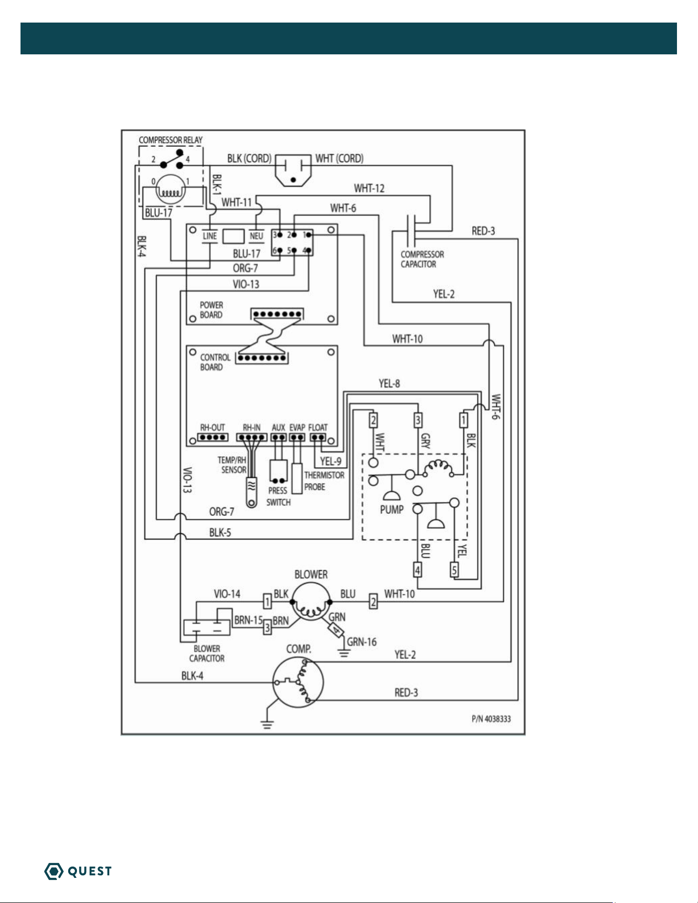
8. WIRING DIAGRAM

20
HI-E DRY 195 INSTALLATION, OPERATION, AND MAINTENANCE INSTRUCTIONS
QUESTCLIMATE.COM(877) 420-1330
9. DECOMMISSIONING
Before carrying out this procedure, it is essential that the technician is completely familiar with the
equipment and all its details. It is recommended good practice that all refrigerants are recovered safely.
Prior to the task being carried out, an oil and refrigerant sample shall be taken in case analysis is required
prior to re-use of recovered refrigerant. It is essential that electrical power is available before the task
commences.
1. Become familiar with the equipment and its operation.
2. Isolate system electrically.
3. Before attempting the procedure, ensure that:
» mechanical handling equipment is available, if required, for handling refrigerant cylinders;
» all personal protective equipment is available and being used correctly;
» the recovery process is supervised at all times by a competent person;
» recovery equipment and cylinders conform to the appropriate standards.
4. Pump down refrigerant system, if possible.
5. If a vacuum is not possible, make a manifold so that refrigerant can be removed from various parts of
the system.
6. Make sure that cylinder is situated on the scales before recovery takes place.
7. Start the recovery machine and operate in accordance with instructions.
8. Do not overfill cylinders (no more than 80 % volume liquid charge).
9. Do not exceed the maximum working pressure of the cylinder, even temporarily.
10. When the cylinders have been filled correctly and the process completed, make sure that the cylinders
and the equipment are removed from site promptly and all isolation valves on the equipment are
closed off.
11. Recovered refrigerant shall not be charged into another REFRIGERATING SYSTEM unless it has been
cleaned and checked.
9.1 LABELLING DECOMMISSION MACHINES
Equipment shall be labelled stating that it has been de-commissioned and emptied of refrigerant. The label
shall be dated and signed. For appliances containing FLAMMABLE REFRIGERANTS, ensure that there are
labels on the equipment stating the equipment contains FLAMMABLE REFRIGERANT.
9.2 REFRIGERANT RECOVERY
When removing refrigerant from a system, either for servicing or decommissioning, it is recommended
good practice that all refrigerants are removed safely.
When transferring refrigerant into cylinders, ensure that only appropriate refrigerant recovery cylinders
are employed. Ensure that the correct number of cylinders for holding the total system charge is available.
All cylinders to be used are designated for the recovered refrigerant and labelled for that refrigerant (i.e.
special cylinders for the recovery of refrigerant). Cylinders shall be complete with pressure-relief valve and
associated shut-off valves in good working order. Empty recovery cylinders are evacuated and, if possible,
cooled before recovery occurs.

21
HI-E DRY 195 INSTALLATION, OPERATION, AND MAINTENANCE INSTRUCTIONS
QUESTCLIMATE.COM(877) 420-1330
The recovery equipment shall be in good working order with a set of instructions concerning the
equipment that is at hand and shall be suitable for the recovery of all appropriate refrigerants including,
when applicable, FLAMMABLE REFRIGERANTS. In addition, a set of calibrated weighing scales shall be
available and in good working order. Hoses shall be complete with leak-free disconnect couplings and
in good condition. Before using the recovery machine, check that it is in satisfactory working order, has
been properly maintained and that any associated electrical components are sealed to prevent ignition
in the event of a refrigerant release. Consult manufacturer if in doubt.
The recovered refrigerant shall be returned to the refrigerant supplier in the correct recovery cylinder,
and the relevant waste transfer note arranged. Do not mix refrigerants in recovery units and especially
not in cylinders.
If compressors or compressor oils are to be removed, ensure that they have been evacuated to an
acceptable level to make certain that FLAMMABLE REFRIGERANT does not remain within the lubricant.
The evacuation process shall be carried out prior to returning the compressor to the suppliers. Only
electric heating to the compressor body shall be employed to accelerate this process. When oil is
drained from a system, it shall be carried out safely.
22
HI-E DRY 195 INSTALLATION, OPERATION, AND MAINTENANCE INSTRUCTIONS
QUESTCLIMATE.COM(877) 420-1330
11. ACCESSORIES
PART NO. DESCRIPTION
4039132 Duct Collar Kit
4021475 Filter
4039075 Muffler Kit
10. SERVICE PARTS:
ITEM PART NO. QTY. DESCRIPTION
1 4035235-08 1 Blower Capacitor
2 4033032-06 1 Capacitor, Run,
50MFD, 370v
3 4036164-13 2 Capillary Tubes
4 4038326 2 Caster, 2”, w/brake
5 4038327 2 Caster, 2”
6 4028566 1 Coil, Condenser
7 4034474-05 1 Coil, Evaporator E-Coat
8 4030131 1 Compressor
9 4030121 1 Compressor Overload
10 4034474-01 1 Condensate Pump
11 4036954 1 Wire Harness, Low Voltage
12 4038332 1 Wire Harness, High Voltage
13 4036524 1 Cord
14 4034716-04 1 Probe, Thermistor
15 4021475 1 Filter, Air
(1.75” X 15.5” X 19.5”)
16 4029510 1 Filter/Drier
17 4024916 1 Hose, Vinyl, .25 x 33 ft.
18 4029894 1 Hose, Vinyl, .56 x 24 in.
19 1970010 1 Relay, SPDT (Omron G7L-
1A-TUB-CB-AC100/120)
20 4020988 1 Service Valve Assembly
w/ Core & Cap
21 4038333 1 Wiring Diagram (not shown)
22 4038116 1 Control Board
23 4038266 1 Blower
24 4036923 1 Power Board
23
24

23
HI-E DRY 195 INSTALLATION, OPERATION, AND MAINTENANCE INSTRUCTIONS
QUESTCLIMATE.COM(877) 420-1330
SEE BACK FOR WARRANTY AND REGISTRATION.
24
HI-E DRY 195 LIMITED WARRANTY
QUESTCLIMATE.COM(877) 420-1330
IMPORTANT WARRANTY INFORMATION
WARRANTOR:
Therma-Stor LLC
4201 Lien Rd
Madison, WI 53704
Telephone: 1-800-533-7533
WHO IS COVERED: This warranty extends only to the original end-user of the Hi-E Dry 195 dehumidifier, and may not be
assigned or transferred.
YEAR ONE: Therma-Stor warrants that, for one (1) year the Hi-E Dry 195 dehumidifier will operate free from any defects in
materials and workmanship, or Therma-Stor will, at its option, repair or replace the defective part(s), free of any charge.
YEAR(S) TWO THROUGH FIVE: Therma-Stor further warrants that for a period of five (5) years, the condenser, evaporator,
and compressor of the Hi-E Dry 195 dehumidifier will operate free of any defects in material or workmanship, or Therma-
Stor, at its option, will repair or replace the defective part(s), provided that all labor and transportation charges for the
part(s) shall be borne by the end-user.
END-USER RESPONSIBILITIES: Warranty service must be performed by a Servicer authorized by Therma-Stor. If the end-
user is unable to locate or obtain warranty service from an authorized Servicer, he should call Therma-Stor at the above
number and ask for the Therma-Stor Service Department, which will then arrange for covered warranty service. Warranty
service will be performed during normal working hours.
The end-user must present proof of purchase (lease) upon request, by use of the warranty card or other reasonable and
reliable means. The end-user is responsible for normal care. This warranty does not cover any defect, malfunction, etc.
resulting from misuse, abuse, lack of normal care, corrosion, freezing, tampering, modification, unauthorized or improper
repair or installation, accident, acts of nature or any other cause beyond Therma-Stor’s reasonable control.
LIMITATION AND EXCLUSIONS: If any Hi-E Dry 195 Dehumidifier part is repaired or replaced, the new part shall be
warranted for only the remainder of the original warranty period applicable thereto (but all warranty periods will be
extended by the period of time, if any, that the Hi-E Dry 195 Dehumidifier is out of service while awaiting covered warranty
service).
UPON THE EXPIRATION OF THE WRITTEN WARRANTY APPLICABLE TO THE HI-E Dry 195 DEHUMIDIFIER OR ANY PART THEREOF, ALL OTHER WARRANTIES
IMPLIED BY LAW, INCLUDING MERCHANTABILITY AND FITNESS FOR A PARTICULAR PURPOSE, SHALL ALSO EXPIRE. ALL WARRANTIES MADE BY THERMA-
STOR ARE SET FORTH HEREIN, AND NO CLAIM MAY BE MADE AGAINST THERMA-STOR BASED ON ANY ORAL WARRANTY. IN NO EVENT SHALL THERMA-STOR,
IN CONNECTION WITH THE SALE, INSTALLATION, USE, REPAIR OR REPLACEMENT OF ANY HI-E Dry 195 DEHUMIDIFIER OR PART THEREOF BE LIABLE UNDER
ANY LEGAL THEORY FOR ANY SPECIAL, INDIRECT OR CONSEQUENTIAL DAMAGES INCLUDING WITHOUT LIMITATION WATER DAMAGE (THE END-USER SHOULD
TAKE PRECAUTIONS AGAINST SAME), LOST PROFITS, DELAY, OR LOSS OF USE OR DAMAGE TO ANY REAL OR PERSONAL PROPERTY.
Some states do not allow limitations on how long an implied warranty lasts, and some do not allow the exclusion or
limitation of incidental or consequential damages, so one or both of these limitation may not apply to you.
LEGAL RIGHTS: This warranty gives you specific legal rights, and you may also have other rights which vary from state to
state.
DO NOT DISCARD
SERIAL
NUMBER
PART
NUMBER
REGISTER YOUR
NEW DEHUMIDIFIER
using the serial number
and part number at
thermastor.com/
registration
or scan code above
PLACE LABEL HERE
FOR INTERNAL
USE ONLY