

Visit our website at: http://www.harborfreight.com
email our technical support at: [email protected]
59477
BENCHTOP ABRASIVE
BLAST CABINET
Owner’s Manual & Safety Instructions
Save This Manual Keep this manual for the safety warnings and precautions, assembly,
operating, inspection, maintenance and cleaning procedures. Write the product’s serial number in the
back of the manual (or month and year of purchase if product has no number). Keep this manual and the
receipt in a safe and dry place for future reference. 23e
When unpacking, make sure that the product is intact
and undamaged. If any parts are missing or broken,
please call 1‑888‑866‑5797 as soon as possible.
Copyright
©
2022 by Harbor Freight Tools
®
. All rights reserved.
No portion of this manual or any artwork contained herein may be reproduced in
any shape or form without the express written consent of Harbor Freight Tools.
Diagrams within this manual may not be drawn proportionally. Due to continuing
improvements, actual product may differ slightly from the product described herein.
Tools required for assembly and service may not be included.
Read this material before using this product.
Failure to do so can result in serious injury.
SAVE THIS MANUAL.
Owner’s Manual & Safety Instructions
Save This Manual Keep this manual for the safety warnings and precautions, assembly,
operating, inspection, maintenance and cleaning procedures. Write the product’s serial
number in the back of the manual (or month and year of purchase if product has no number).
Keep this manual and the receipt in a safe and dry place for future reference.
When unpacking, make sure that the product is intact
and undamaged. If any parts are missing or broken,
please call 1‑888‑866‑5797 as soon as possible.
Copyright
©
2022 by Harbor Freight Tools
®
. All rights reserved.
No portion of this manual or any artwork contained herein may be reproduced in
any shape or form without the express written consent of Harbor Freight Tools.
Diagrams within this manual may not be drawn proportionally. Due to continuing
improvements, actual product may differ slightly from the product described herein.
Tools required for assembly and service may not be included.
read this material before using this product.
Failure to do so can result in serious injury.
SaVe tHiS ManuaL.
Page 2 For technical questions, please call 1-888-866-5797. Item 59477
SaFety OperatiOn MaintenanceSetup
table of contents
Safety ......................................................... 3
Specifications ............................................. 9
Setup ......................................................... 10
Operation ................................................... 14
Maintenance .............................................. 17
Parts List and Diagram .............................. 20
Warranty .................................................... 24
WarninG SyMBOLS anD DeFinitiOnS
This is the safety alert symbol. It is used to alert you to potential
personal injury hazards. Obey all safety messages that
follow this symbol to avoid possible injury or death.
Indicates a hazardous situation which, if not avoided,
will result in death or serious injury.
Indicates a hazardous situation which, if not avoided,
could result in death or serious injury.
Indicates a hazardous situation which, if not avoided,
could result in minor or moderate injury.
Addresses practices not related to personal injury.

Page 3For technical questions, please call 1-888-866-5797.Item 59477
SaFetyOperatiOnMaintenance Setup
iMpOrtant SaFety inStructiOnS
inStructiOnS pertaininG tO a riSK OF Fire,
eLectric SHOcK, Or inJury tO perSOnS
WarninG – When using tools, basic precautions should always be followed, including the following:
General
to reduce the risks of electric shock, fire, and injury to persons,
read all the instructions before using the tool.
Work area
1. Keep the work area clean and well lighted.
Cluttered benches and dark areas increase the
risks of electric shock, fire, and injury to persons.
2. Do not operate the tool in explosive
atmospheres, such as in the presence
of flammable liquids, gases, or dust.
The tool is able to create sparks resulting
in the ignition of the dust or fumes.
3. Keep bystanders, children, and visitors away
while operating the tool. Distractions are
able to result in the loss of control of the tool.
personal Safety
1. Stay alert. Watch what you are doing and
use common sense when operating the tool.
Do not use the tool while tired or under the
influence of drugs, alcohol, or medication.
A moment of inattention while operating the
tool increases the risk of injury to persons.
2. Dress properly. Do not wear loose
clothing or jewelry. contain long hair.
Keep hair, clothing, and gloves away from
moving parts. Loose clothes, jewelry, or long
hair increases the risk of injury to persons as
a result of being caught in moving parts.
3. avoid unintentional starting. Be sure the switch
is off before connecting to the air supply.
Do not carry the tool with your finger on the switch or
connect the tool to the air supply with the switch on.
4. Do not overreach.
Keep proper footing and balance at all times.
Proper footing and balance enables better
control of the tool in unexpected situations.
5. use safety equipment.
A dust mask, non‑skid safety shoes
and a hard hat must be used for the
applicable conditions.
6. always wear eye protection.
Wear ANSI‑approved safety goggles
under blast hood.
7. always wear hearing protection
when using the tool.
Prolonged exposure to high intensity
noise is able to cause hearing loss.
8. risk of electric Shock. this tool is not
provided with an insulated gripping surface.
Contact with a ″live″ wire will also make exposed
metal parts of the tool ″live″ and shock the operator.
9. avoid body contact with
grounded surfaces such as pipes, radiators,
ranges and refrigerators. There is an increased
risk of electric shock if your body is grounded.
10. explore the workpiece to avoid contact
with hidden wiring. Thoroughly investigate
the workpiece for possible hidden wiring
before performing work. Contact with
live wiring will shock the operator.
11. Wear heavy-duty blast gloves during use.

Page 4 For technical questions, please call 1-888-866-5797. Item 59477
SaFety OperatiOn MaintenanceSetup
tool use and care
1. Use clamps or another practical way to secure
and support the workpiece to a stable platform.
Holding the work by hand or against the body is
unstable and is able to lead to loss of control.
2. Do not force the tool. Use the correct tool for the
application. The correct tool will do the job better
and safer at the rate for which the tool is designed.
3. Do not use the tool if the trigger does
not turn the tool on or off. Any tool that
cannot be controlled with the trigger is
dangerous and must be repaired.
4. Disconnect the tool from the air source
before making any adjustments, changing
accessories, or storing the tool. Such preventive
safety measures reduce the risk of starting the
tool unintentionally. Turn off and detach the air
supply, safely discharge any residual air pressure,
and release the throttle and/or turn the switch to
its off position before leaving the work area.
5. Store the tool when it is idle out of reach
of children and other untrained persons.
A tool is dangerous in the hands of untrained users.
6. Maintain the tool with care. Keep a cutting
tool sharp and clean. A properly maintained tool,
with sharp cutting edges reduces the risk
of binding and is easier to control.
7. check for misalignment or binding of moving
parts, breakage of parts, and any other condition
that affects the tool’s operation. If damaged,
have the tool serviced before using. Many accidents
are caused by poorly maintained tools.
There is a risk of bursting if the tool is damaged.
8. use only accessories that are identified by the
manufacturer for the specific tool model. Use of
an accessory not intended for use with the specific
tool model, increases the risk of injury to persons.
Page 5For technical questions, please call 1-888-866-5797.Item 59477
SaFetyOperatiOnMaintenance Setup
Service
1. Tool service must be performed only
by qualified repair personnel.
2. When servicing a tool, use only identical
replacement parts. use only authorized parts.
air Source
1. never connect to an air source that
is capable of exceeding 200 psi.
Over pressurizing the tool may cause
bursting, abnormal operation,
breakage of the tool or serious injury
to persons. Use only clean, dry, regulated
compressed air at the rated pressure or within the
rated pressure range as marked on the tool.
Always verify prior to using the tool that the air
source has been adjusted to the rated air pressure
or within the rated air‑pressure range.
2. Never use oxygen, carbon dioxide, combustible
gases or any bottled gas as an air source
for the tool. Such gases are capable of
explosion and serious injury to persons.
SaVe tHeSe inStructiOnS.

Page 6 For technical questions, please call 1-888-866-5797. Item 59477
SaFety OperatiOn MaintenanceSetup
Specific Safety instructions
1. The warnings and precautions discussed in this
manual cannot cover all possible conditions and
situations that may occur. It must be understood
by the operator that common sense and caution
are factors which cannot be built into this
product, but must be supplied by the operator.
2. avoid working alone. If an accident
happens, an assistant can bring help.
3. Maintain labels and nameplates on the
Blast cabinet. These carry important
information. If unreadable or missing, contact
Harbor Freight Tools for a replacement.
4. Maintain a firm grip on the
Blast Gun when in use.
5. never point the Blast Gun toward yourself,
other people, or animals. Keep all people
and animals safely away from the work area.
6. industrial applications must
follow OSHa requirements.
7. Whenever possible, perform an abrasive
blasting test on a small area of the object to
be blasted. If necessary, adjust the distance
to the object and/or change the Nozzle of
the Blast Gun for more effective results.
8. read and understand all safety warnings
and precautions as outlined in the
manufacturer’s manual for the object
you intend to blast with abrasives.
9. Obey the manual for the air compressor
used to power this tool.
10. Install an in‑line shutoff valve to allow
immediate control over the air supply in an
emergency, even if a hose is ruptured.
Silicosis Safety Measures
DO nOt uSe SanD!
abrasive blasting with sand (which contains crystalline silica) can cause
silicosis (a serious lung disease), cancer and death. to reduce crystalline silica
exposures in the workplace and prevent silicosis and silicosis-related deaths:
1. Prohibit silica sand (or other substances
containing more than 1% crystalline silica)
as an abrasive blasting material and
substitute less hazardous materials.
2. Conduct air monitoring to measure
worker exposures.
3. Use containment methods such as blast‑cleaning
machines and cabinets to control the hazard
and protect adjacent workers from exposure.
4. Practice good personal hygiene to avoid
unnecessary exposure to silica dust.
5. Wear washable or disposable protective
clothes at the work site. Shower and change
into clean clothes before leaving the work site
to prevent contamination of cars, homes and
other work areas. Avoid skin exposure.
6. Always wear a NIOSH approved respirator and
safety goggles. Ventilate the work area properly.
7. Provide periodic medical examinations for all
workers who may be exposed to crystalline silica.
8. Post signs to warn workers about the hazard and to
inform them about required protective equipment.
9. Provide workers with training that includes
information about health effects, work practices
and protective equipment for crystalline silica.
10. Report all cases of silicosis to State health
departments and to OSHA or the Mine Safety
and Health Administration (MSHA).

Page 7For technical questions, please call 1-888-866-5797.Item 59477
SaFetyOperatiOnMaintenance Setup
Vibration precautions
This tool vibrates during use. Repeated or
long‑term exposure to vibration may cause
temporary or permanent physical injury,
particularly to the hands, arms and shoulders.
To reduce the risk of vibration‑related injury:
1. Anyone using vibrating tools regularly or for
an extended period should first be examined
by a doctor and then have regular medical
check‑ups to ensure medical problems are not
being caused or worsened from use. Pregnant
women or people who have impaired blood
circulation to the hand, past hand injuries,
nervous system disorders, diabetes, or Raynaud's
Disease should not use this tool. If you feel
any symptoms related to vibration (such as
tingling, numbness, and white or blue fingers),
seek medical advice as soon as possible.
2. Do not smoke during use. Nicotine reduces
the blood supply to the hands and fingers,
increasing the risk of vibration‑related injury.
3. Wear suitable gloves to reduce the
vibration effects on the user.
4. Use tools with the lowest vibration
when there is a choice.
5. Include vibration‑free periods each day of work.
6. Grip tool as lightly as possible (while still keeping
safe control of it). Let the tool do the work.
7. To reduce vibration, maintain
tool as explained in this manual.
If abnormal vibration occurs, stop immediately.
SaVe tHeSe inStructiOnS.
Page 8 For technical questions, please call 1-888-866-5797. Item 59477
SaFety OperatiOn MaintenanceSetup
Symbols and Specific Safety instructions
Symbol Definitions
Symbol property or statement
pSi
Pounds per square inch of pressure
cFM
Cubic Feet per Minute flow
ScFM
Cubic Feet per Minute flow
at standard conditions
npt
National pipe thread, tapered
npS
National pipe thread, straight
WARNING marking
concerning Risk of Eye Injury.
Wear ANSI‑approved eye protection.
Symbol property or statement
WARNING marking concerning Risk of
Hearing Loss. Wear hearing protection.
WARNING marking concerning
Risk of Respiratory Injury. Wear
NIOSH‑approved dust mask/respirator.
WARNING marking concerning
Risk of Explosion.
Page 9For technical questions, please call 1-888-866-5797.Item 59477
SaFetyOperatiOnMaintenance Setup
Functional Description
Specifications
Compressor Requirements
5 HP or larger
compressor
Maximum Air Pressure 100 PSI
Air Inlet 1/4″ NPT
Nozzle Type
Ceramic ‑ .18″,
.19″, .22″, .27″
Average Air Consumption 11 CFM @ 90 PSI
Operating Air Pressure Up to 100 PSI
Hopper Capacity 30 lb
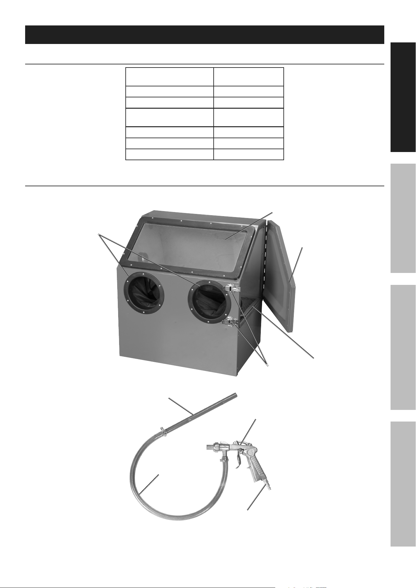
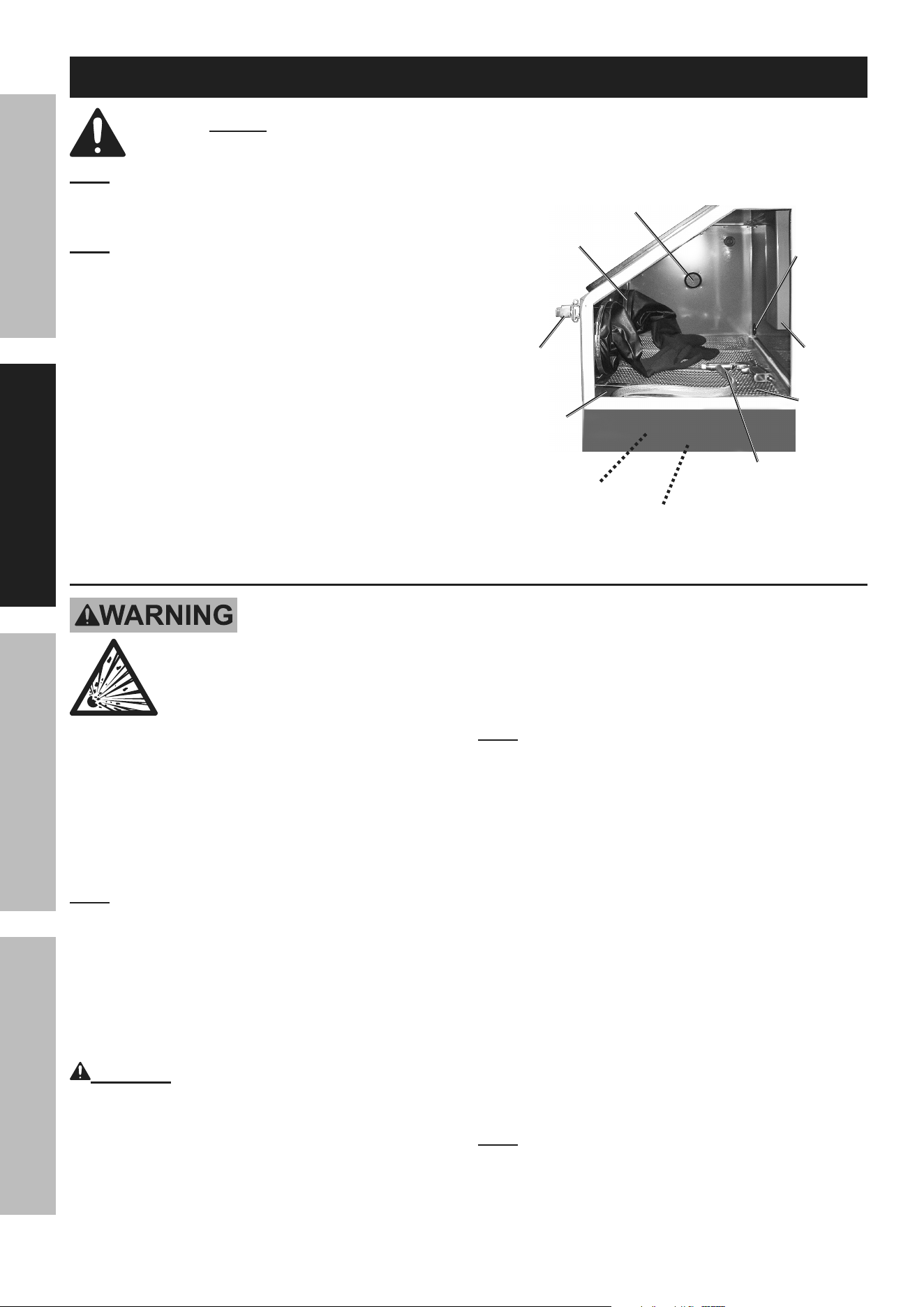
components and controls
Hopper (11)
Glove ports (8)
Window (2)
Door (15)
Door
Latches (9)
Blast Gun (14)
Siphon
Hose (13)
Siphon tube (12)
air Hose
connector (12)
Page 10 For technical questions, please call 1-888-866-5797. Item 59477
SaFety OperatiOn MaintenanceSetup
initial tool Set up/assembly
read the entire iMpOrtant SaFety inFOrMatiOn section at the beginning of this
manual including all text under subheadings therein before set up or use of this product.
note: For additional information regarding the
parts listed in the following pages, refer to the
Assembly Diagram near the end of this manual.
note: This air tool may be shipped with a protective plug
covering the air inlet. Remove this plug before set up.
Verify all hose clamps and fittings are
tightened on the Siphon Hose, Siphon
Tube, and air supply hose to the gun.
cap (38)
(underneath unit)
Dust collection Outlet
Grate
(10)
air
Hose
inlet
Vent
Siphon-Gun assembly
Opening
in Grate
for Siphon
tube (12)
Blast Gloves (7)
Hopper (11)
Door
Latch (9)
air Supply
tO preVent SeriOuS inJury FrOM eXpLOSiOn:
use only clean, dry, regulated, compressed air to power this tool.
Do not use oxygen, carbon dioxide, combustible gases,
or any other bottled gas as a power source for this tool.
1. Incorporate a filter, regulator with pressure gauge,
dryer, in‑line shutoff valve, and quick coupler for
best service, as shown on Figure A on page 12
and Figure B on page 13. an in-line shutoff
ball valve is an important safety device because
it controls the air supply even if the air hose
is ruptured. the shutoff valve should be a
ball valve because it can be closed quickly.
note: Do not use an oiler system with this tool.
The oil will mix with the material being
propelled, causing poor results.
2. Attach an air hose to the compressor's air outlet.
Connect the air hose to the air inlet of the tool.
Other components, such as a coupler plug
and quick coupler, will make operation
more efficient, but are not required.
WarninG! tO preVent SeriOuS inJury
FrOM acciDentaL OperatiOn:
Do not install a female quick coupler on the tool.
Such a coupler contains an air valve that will
allow the air tool to retain pressure and operate
accidentally after the air supply is disconnected.
note: Air flow, and therefore tool performance,
can be hindered by undersized air supply components.
The air hose must be long enough to reach
the work area with enough extra length to
allow free movement while working.
3. Turn the tool's throttle or switch to the off position;
refer to Operation section for description of controls.
4. Close the in‑line shutoff valve between
the compressor and the tool.
5. Turn on the air compressor according to
the manufacturer's directions and allow it
to build up pressure until it cycles off.
6. Adjust the air compressor's output regulator
so that the air output is enough to properly
power the tool, but the output will not exceed
the tool's maximum air pressure at any time.
Adjust the pressure gradually, while checking the
air output gauge to set the right pressure range.
note: For best results, use high‑flow fittings.
Minimize number of fittings and air hose length.
Page 11For technical questions, please call 1-888-866-5797.Item 59477
SaFetyOperatiOnMaintenance Setup
7. Inspect the air connections for leaks.
Repair any leaks found.
8. If the tool will not be used at this time, turn off
and detach the air supply, safely discharge
any residual air pressure, and release
the throttle and/or turn the switch to its off
position to prevent accidental operation.
9. Residual air pressure should not be present
after the tool is disconnected from the air supply.
However, it is a good safety measure to
attempt to discharge the tool in a safe fashion
after disconnecting to ensure that the tool
is disconnected and not powered.
10. This item requires 11 CFM at 90 PSI. Follow
runtime chart. Do not use for extended periods
to avoid excess wear of compressor pump.
uSaGe tiMeS per cOMpreSSOr
cOMpreSSOr SiZe
(Gallons)
cOMpreSSOr ratinG
(pSi) (ScFM)
estimated run time
at 90pSi (Seconds)
3 110 0.6 Not Recommended
10 175 4.3 45
20 135 4.0 30
27 200 5.1 170
80 175 15.6 Continuous
• Table accounts for compressor pump running while using tool.
• Operating the tool at lower pressures will extend
run time, but may reduce performance.
• Compressors with increased pressure, flow or tank size will increase run time.
• Improperly sized fittings and hoses may reduce air pressure and run time.
Page 12 For technical questions, please call 1-888-866-5797. Item 59477
SaFety OperatiOn MaintenanceSetup
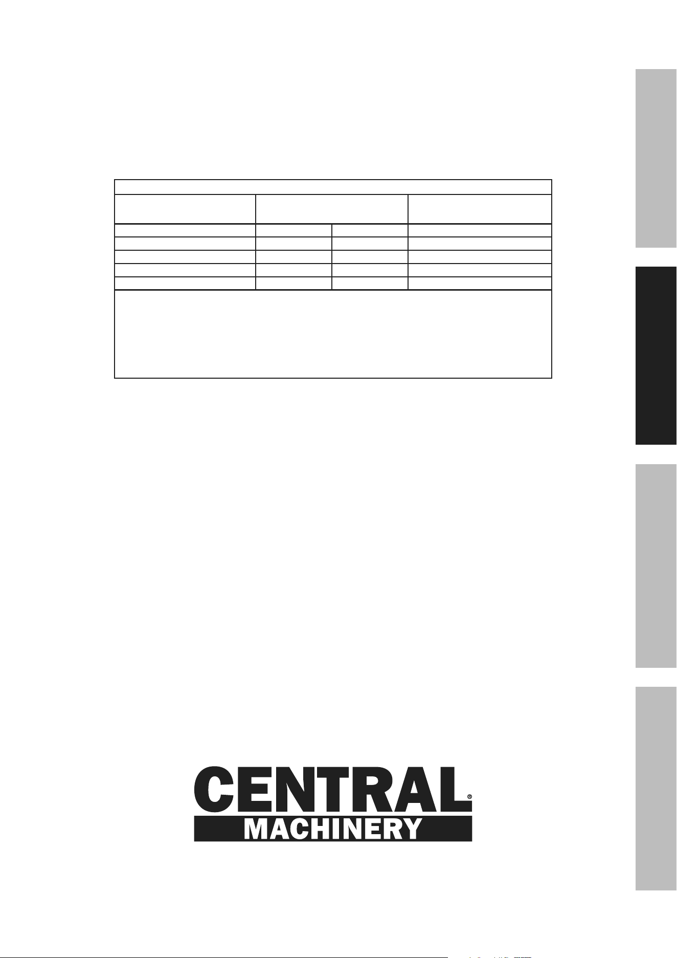
Figure a: portable air Supply Setup
G
A
E
E
H
F
B
Non-lubricated
Tools
Lubricated
Tools
A
B
C
C
D
A
Description Function
A Air Hose Connects air to tool
B Filter Prevents dirt and condensation from damaging tool or workpiece
C Regulator Adjusts air pressure to tool
D Lubricator (optional) For air tool lubrication
E Coupler and Plug Provides quick connection and release
F Leader Hose (optional) Increases coupler life
G Air Cleaner / Dryer (optional) Prevents water vapor from damaging workpiece
H Air Adjusting Valve (optional) For fine tuning airflow at tool
Page 13For technical questions, please call 1-888-866-5797.Item 59477
SaFetyOperatiOnMaintenance Setup
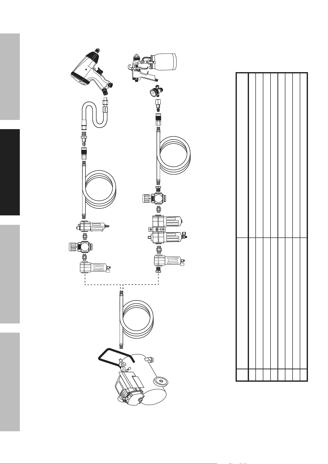
Figure B: Stationary air Supply Setup
N
L
L O
M
C
C
Non-lubricated Tools
Lubricated
Tools
H
I
I
J
J
K
H
F
G
E
Slope
F
F
B
B
A
A
C
D
Description Function
A Vibration Pads For noise and vibration reduction
B Anchor Bolts Secures air compressor in place
C Ball Valve Isolates sections of system for maintenance
D Isolation Hose For vibration reduction
E Main Air Line ‑ 3/4″ minimum recommended Distributes air to branch lines
F Ball Valve To drain moisture from system
G Branch Air Line ‑1/2″ minimum recommended Brings air to point of use
H Air Hose Connects air to tool
I Filter Prevents dirt and condensation from damaging tool or workpiece
J Regulator Adjusts air pressure to tool
K Lubricator (optional) For air tool lubrication
L Coupler and Plug Provides quick connection and release
M Leader Hose (optional) Increases coupler life
N Air Cleaner / Dryer (optional) Prevents water vapor from damaging workpiece
O Air Adjusting Valve (optional) For fine tuning airflow at tool

Page 14 For technical questions, please call 1-888-866-5797. Item 59477
SaFety OperatiOn MaintenanceSetup
Operating instructions
read the entire iMpOrtant SaFety inFOrMatiOn section at the beginning of this
manual including all text under subheadings therein before set up or use of this product.
inspect tool before use, looking for damaged, loose, and missing parts.
if any problems are found, do not use tool until repaired.
tool Set up
tO preVent SeriOuS inJury FrOM acciDentaL OperatiOn:
turn off the tool, detach the air supply, safely discharge any residual air pressure
in the tool, and release the throttle and/or turn the switch to its off position before
performing any inspection, maintenance, or cleaning procedures.
tO preVent SeriOuS inJury:
Do not adjust or tamper with any control or component in a way not specifically explained within
this manual. improper adjustment can result in tool failure or other serious hazards.
1. Wear protective gear including a
niOSH-approved respirator.
2. Close the Air Supply Valve, Abrasive Valve,
then the Throttle Valve.
3. Pull the ring on the Safety Valve out to make sure its
Tank is not pressurized, then release it. Check the
Air Pressure Gauge to make sure it reads ″0″ PSI.
WarninG! tO preVent SeriOuS
inJury: Do not use sand or other blasting
materials that contain crystalline silica.
cautiOn! Exposure to aluminum oxide (an abrasive
media) can result in eye, skin and breathing irritation.
note: Use only dry and clean abrasives
to avoid clogging the Blaster.
note: Change the Nozzle as needed to suit
the abrasive grit. Refer to Nozzle Replacement
on page 18. The included nozzles are
not designed for use with steel shot.
4. To install or change the Nozzle, loosen the
Nozzle Lock (1A). Slide the desired Nozzle
in place and tighten the Nozzle Lock.
note: By changing to the next larger size of Nozzle,
production can increase significantly. Larger size
Nozzles produce a larger cleaning pattern. This also
requires a higher air pressure and greater air flow.
5. Slide one end of the Siphon Hose (13)
onto the Siphon Tube (12) and the other
end onto the Blast Gun (14).
6. Insert the Siphon Tube through the
corner opening of the Grate (10) so that
it is resting in the Hopper (11).
7. It is recommended that you set up a vacuum dust
collector (sold separately) to remove media dust
while blasting. Remove cover on left side of Cabinet
and attach the vacuum hose through the Dust
Collection Outlet.
When using a vacuum dust collector, clean
the filter periodically to maintain good
suction and effectiveness of the vacuum.
Use the appropriate vacuum for the job.
note: If dust collector is not used, the round
cover must be in place on side of Cabinet.
8. Open the Cabinet door and fill the Hopper with
approximately 5 pounds of an appropriate abrasive,
such as glass beads or walnut shells, checking
to ensure that the abrasives are dry and clean.
Do not use harsh abrasives such as steel shot or
aluminum oxide. Do not overload the hopper with
media as it can inhibit media flow to the gun.
9. Set the compressor’s pressure regulator
to 90 PSI. Do not set it over 100 PSI.
10. Route the compressor hose from the outside
of the Cabinet to the inside through the Air
Hose Inlet in the back of the Cabinet, then
connect it to the Air Hose Connector (12A)
on the Blast Gun inside the Cabinet.
11. Holding the Blast Gun so that it is pointing
away from you, open the shut‑off valve.
If leaking is detected, disconnect the
air hose and repair before use.

Page 15For technical questions, please call 1-888-866-5797.Item 59477
SaFetyOperatiOnMaintenance Setup
Workpiece and Work area Set up
1. Designate a work area that is clean and well‑lit.
The work area must not allow access by children
or pets to prevent distraction and injury.
2. Route the air hose along a safe route to reach
the work area without creating a tripping hazard
or exposing the hose to possible damage.
The hose must be long enough to reach
the work area with enough extra length to
allow free movement while working.
3. Place the Blast Cabinet on a sturdy level work
surface, positioning the Cabinet at a level so
that you can comfortably access the Glove
openings and easily see into the Blast Cabinet
through the Window. The work surface needs
to be able to support the weight of the Blast
Cabinet and the abrasive which will fill the
Hopper, the work piece and any additional
material required to be close at hand.
4. Secure loose workpieces using a vise or clamps
(not included) to prevent movement while working.
5. There must not be hazardous objects
(such as utility lines or foreign objects) nearby
that will present a hazard while working.

Page 16 For technical questions, please call 1-888-866-5797. Item 59477
SaFety OperatiOn MaintenanceSetup
General Operating instructions
WarninG! tO preVent SeriOuS inJury:
Wear anSi-approved safety goggles and niOSH-
approved respirator under Blast Hood, and heavy-
duty blast gloves, when operating the Blaster.
1. To protect the compressor and its engine
or motor from damage by abrasive or dust
from abrasive blasting, keep the compressor
upwind of the Blaster or in a separate room.
2. close the air Supply Valve, abrasive Valve,
and throttle Valve, then connect
and turn on the air supply.
3. Place the workpiece to be blasted on
the Grate inside the Blast Cabinet.
4. If needed, turn on LED lamp.
5. Close the Door (15) and hook the Door Latch (9)
over the door flange and lock in place. Check
to make sure the Latch is secured.
6. Place your hands into the Blast Gloves (7), making
sure your fingers are in the proper positions and that
you can easily move your hands and grip objects.
nOtice: Do not attempt to regulate the air/blast media
mixture discharge rate with the Trigger Valve.
Doing so will ruin it.
7. Grip the gun with one hand. Point the nozzle at
the bottom of the Cabinet and operate the Gun
for a moment to ensure everything is working
correctly. If leaking is detected, or blasting material
dust is escaping the side door seals, disconnect
the air hose and have it repaired before using.
8. Hold the object you are working with in your
other hand. Position your fingers so the Blast
Glove is not in the way of the area you are
blasting. You may have to re‑position your
fingers many times during the blasting to ensure
that you reach every area of your object.
9. Squeeze the Trigger on the Blast Gun to begin
operation. Release the Trigger to stop.
Aim the nozzle directly at the surface of the
workpiece. Bring the nozzle to within 2 inches
of the workpiece if necessary. Move the Gun in
a side‑to‑side or circular motion, always making
sure that your fingers are not in the way.
Use even passes of the Gun to remove
rust, body filler, or other soft materials.
10. To check on the progress of your blasting, remove
your hand from the gun first and pull your hand
from the Glove. Remove your other hand. Turn
off compressor and dust collection system (if
equipped). Wait for the air inside the cabinet to
clear. Once the gun is off, open the door and
inspect the workpiece. If additional blasting is
required, follow steps 1 through 8 as needed.
note: Use caution when sandblasting unfamiliar
material. Test the tool on a small area before
proceeding. This will ensure you will not damage
or pit the material you wish to sandblast.
note: The flow rate of the abrasive may be irregular
when the unit is first started. If the abrasive is dry, the
flow rate will stabilize in approximately one minute.
11. If the tool requires more force to accomplish
the task, verify that the tool receives sufficient,
unobstructed airflow (CFM) and increase the
pressure (PSI) output of the regulator up to the
maximum air pressure rating of this tool.
cautiOn! tO preVent inJury FrOM
tOOL Or acceSSOry FaiLure:
Do not exceed the tool's
maximum air pressure rating.
If the tool still does not have sufficient force
at maximum pressure and sufficient airflow,
then a larger tool may be required.
12. Once completed, remove your hands from the
Gloves and shut off the compressor. Open the Door
and remove the workpiece from the Blast Cabinet.
13. To prevent accidents, turn off the tool, detach the air
supply, safely discharge any residual air pressure
in the tool, and release the throttle and/or turn the
switch to its off position after use. Clean external
surfaces of the tool with clean, dry cloth.
Then store the tool indoors out of children's reach.

Page 17For technical questions, please call 1-888-866-5797.Item 59477
SaFetyOperatiOnMaintenance Setup
user-Maintenance instructions
procedures not specifically explained in this manual must
be performed only by a qualified technician.
tO preVent SeriOuS inJury FrOM acciDentaL OperatiOn:
turn off the tool, detach the air supply, safely discharge any residual air pressure
in the tool, and release the throttle and/or turn the switch to its off position before
performing any inspection, maintenance, or cleaning procedures.
tO preVent SeriOuS inJury FrOM tOOL FaiLure:
Do not use damaged equipment. if abnormal noise, vibration,
or leaking air occurs, have the problem corrected before further use.
cleaning, Maintenance, and Lubrication
note: These procedures are in addition to the regular checks and maintenance
explained as part of the regular operation of the air‑operated tool.
1. BeFOre eacH uSe, inspect the general
condition of the tool. Check for:
• loose hardware or housing,
• misalignment or binding of moving parts,
• cracked or broken parts, and
• any other condition that may
affect its safe operation.
2. Daily - air Supply Maintenance:
Every day, maintain the air supply according
to the component manufacturers' instructions.
Drain the moisture filter regularly.
Performing routine air supply maintenance
will allow the tool to operate more safely
and will also reduce wear on the tool.
3. Quarterly (every 3 months) –
tool Disassembly, cleaning, and inspection:
Have the internal mechanism cleaned, inspected,
and lubricated by a qualified technician.
a. Disconnect the dust collection
system from the Blast Cabinet.
b. Disconnect Air Hose and Syphon
Hoses from the Gun.
cleaning the Hopper
It is not necessary to remove the blasting medium
from the Hopper after every use. However,
clean out the Hopper when a different blasting
medium is to be used or when the medium
gets worn down. To clean the Hopper:
WarninG: Wear ANSI‑approved safety goggles,
full face shield and a NIOSH‑approved protective
dust mask or respirator when replacing the
abrasive medium in the Blast Cabinet.
1. Remove the Gun from the Cabinet.
2. Pull the Gloves through the glove holes so that they
are out of the way of the inside of the Blast Cabinet.
3. Remove the Grate from the Blast Cabinet.
4. Straddle the Blast Cabinet over two saw
horses (sold separately) with an open
container below which is large enough to
hold the abrasive material in the hopper.
5. Unthread the Cap (38) at the bottom
of the Hopper and allow the abrasive
medium to flow into the container.
6. Use your compressor set at 10 PSI to help blow
any excess abrasive out of the hopper and
into the container. Also, use the compressor
to clean abrasive out of the Blast Gun and
the Siphon Hose and Siphon Tube.
7. Replace the Cap and the Grate
once the Hopper is empty.
8. Push the Gloves back into the Blast Cabinet.
9. Reassemble the Siphon Hose, Siphon
Tube and Blast Gun and fill the Hopper
with new blasting medium.

Page 18 For technical questions, please call 1-888-866-5797. Item 59477
SaFety OperatiOn MaintenanceSetup
Blast Gun Maintenance
After every use, clean out the Blast
Gun. To clean the gun:
1. Remove the Siphon Hose from the Blast Gun.
2. Operate the Gun for a few seconds
to clear the passages.
3. Turn off the shut‑off valve.
4. Disconnect the air compressor.
5. Discharge any residual air from the line and the Gun.
6. When re‑using abrasive, sharp edges of abrasive
particles eventually become rounded and lose
cutting ability. At this point, replace the abrasive.
7. The parts of the tool that require frequent
wear inspection and occasional replacement
are those that carry the air/abrasive mixture.
Pay particular attention to the Abrasive Hose,
O‑Rings, Abrasive Valve, and Blast Gun
components (Trigger Valve, Nozzle), as they will
wear out much more quickly than the other pieces.
Sandblasting is a damaging operation. In time, the
internal parts of the Blast Gun will become worn.
When performance of the Blast Gun decreases,
take it to a qualified service technician for repair.
cautiOn! Air leaks in any of the above mentioned
parts need to be repaired before use.
abrasive Hose inspection:
When new, the Abrasive Hose has 1/2″ ID.
The Abrasive Hose will need to be replaced
when its side wall develops leaks or
shows blisters on the surface.
WarninG! tO preVent SeriOuS inJury:
the abrasive Hose could have residual
abrasive or suddenly burst. point the Blast
Gun in a safe direction and wear all
safety gear when doing this test.
1. close the air Supply Valve, abrasive Valve, and
throttle Valve, then release the trigger Valve.
then connect and turn on the air supply.
2. Adjust the air pressure to 60‑125 PSI.
3. Open the Air Supply Valve.
4. Open the Throttle Valve.
5. Then, run your fingers along the length of the
Abrasive Hose. An enlarged spot (or bubble)
indicates a weakened section of the Abrasive
Hose. Do not use the Blaster if this problem is
present - replace the entire abrasive Hose first.
nozzle replacement
To change Blast Gun Nozzle size to suit the
blast media being used or to replace a worn
Nozzle, use the following procedure:
1. Unscrew and remove the Nozzle Cap Nut.
2. Remove the old Nozzle.
3. Position the Nozzle Gasket against the Adapter.
4. Position the replacement Nozzle
against the Nozzle Gasket.
5. Screw the Nozzle Cap Nut back onto the Adapter
to secure the Nozzle Gasket and Nozzle in place.
nozzle
Lock
air Jet
Gun Body
nozzle
Page 19For technical questions, please call 1-888-866-5797.Item 59477
SaFetyOperatiOnMaintenance Setup
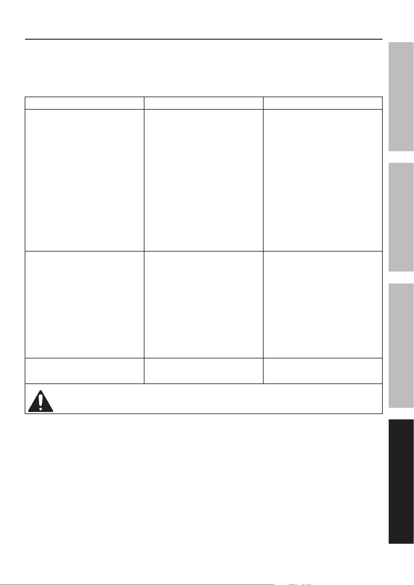
troubleshooting
1. Excess moisture will cause the blast media to slow or stop flowing through the Abrasive Outlet Manifolds. To
correct, check the blast media by pouring a 6″ cone of blast media on dry newspaper. After several minutes,
remove the blast media from the newspaper. Do not use the blast media if the newspaper is moist.
2. Poor or irregular flow of the blast media may also be due to low air pressure or a worn Blast Gun Nozzle.
To correct, increase the air pressure (to no more than 125 PSI) and/or replace the worn Nozzle.
problem possible causes Likely Solutions
Decreased output. 1. Not enough air pressure and/or air
flow.
2. Obstructed trigger.
3. Blocked air inlet screen
(if equipped).
4. Air leaking from loose housing.
5. Mechanism contaminated.
1. Check for loose connections
and make sure that air supply is
providing enough air flow (CFM)
at required pressure (PSI) to the
tool's air inlet. Do not exceed
maximum air pressure.
2. Clean around trigger to
ensure free movement.
3. Clean air inlet screen of buildup.
4. Make sure housing is properly
assembled and tight.
5. Have qualified technician
clean and lubricate mechanism.
Install in‑line filter in air supply
as stated in Setup: Air Supply.
Severe air leakage.
(Slight air leakage is normal,
especially on older tools.)
1. Cross‑threaded housing
components.
2. Loose housing.
3. Damaged valve or housing.
4. Dirty, worn or damaged valve.
1. Check for incorrect alignment
and uneven gaps. If cross‑
threaded, disassemble
and replace damaged
parts before use.
2. Tighten housing assembly.
If housing cannot tighten properly,
internal parts may be misaligned.
Technician needs to disassemble
tool, align parts and reassemble.
3. Replace damaged components.
4. Clean or replace valve assembly.
Housing heats during use. Worn parts. Have qualified technician
inspect internal mechanism
and replace parts as needed.
Follow all safety precautions whenever diagnosing or servicing the tool.
Disconnect air supply before service.

Page 20 For technical questions, please call 1-888-866-5797. Item 59477
SaFety OperatiOn MaintenanceSetup
parts List and Diagram
pLeaSe reaD tHe FOLLOWinG careFuLLy
THE MANUFACTURER AND/OR DISTRIBUTOR HAS PROVIDED THE PARTS LIST AND ASSEMBLY DIAGRAM
IN THIS MANUAL AS A REFERENCE TOOL ONLY. NEITHER THE MANUFACTURER OR DISTRIBUTOR
MAKES ANY REPRESENTATION OR WARRANTY OF ANY KIND TO THE BUYER THAT HE OR SHE IS
QUALIFIED TO MAKE ANY REPAIRS TO THE PRODUCT, OR THAT HE OR SHE IS QUALIFIED TO REPLACE
ANY PARTS OF THE PRODUCT. IN FACT, THE MANUFACTURER AND/OR DISTRIBUTOR EXPRESSLY
STATES THAT ALL REPAIRS AND PARTS REPLACEMENTS SHOULD BE UNDERTAKEN BY CERTIFIED AND
LICENSED TECHNICIANS, AND NOT BY THE BUYER. THE BUYER ASSUMES ALL RISK AND LIABILITY
ARISING OUT OF HIS OR HER REPAIRS TO THE ORIGINAL PRODUCT OR REPLACEMENT PARTS
THERETO, OR ARISING OUT OF HIS OR HER INSTALLATION OF REPLACEMENT PARTS THERETO.
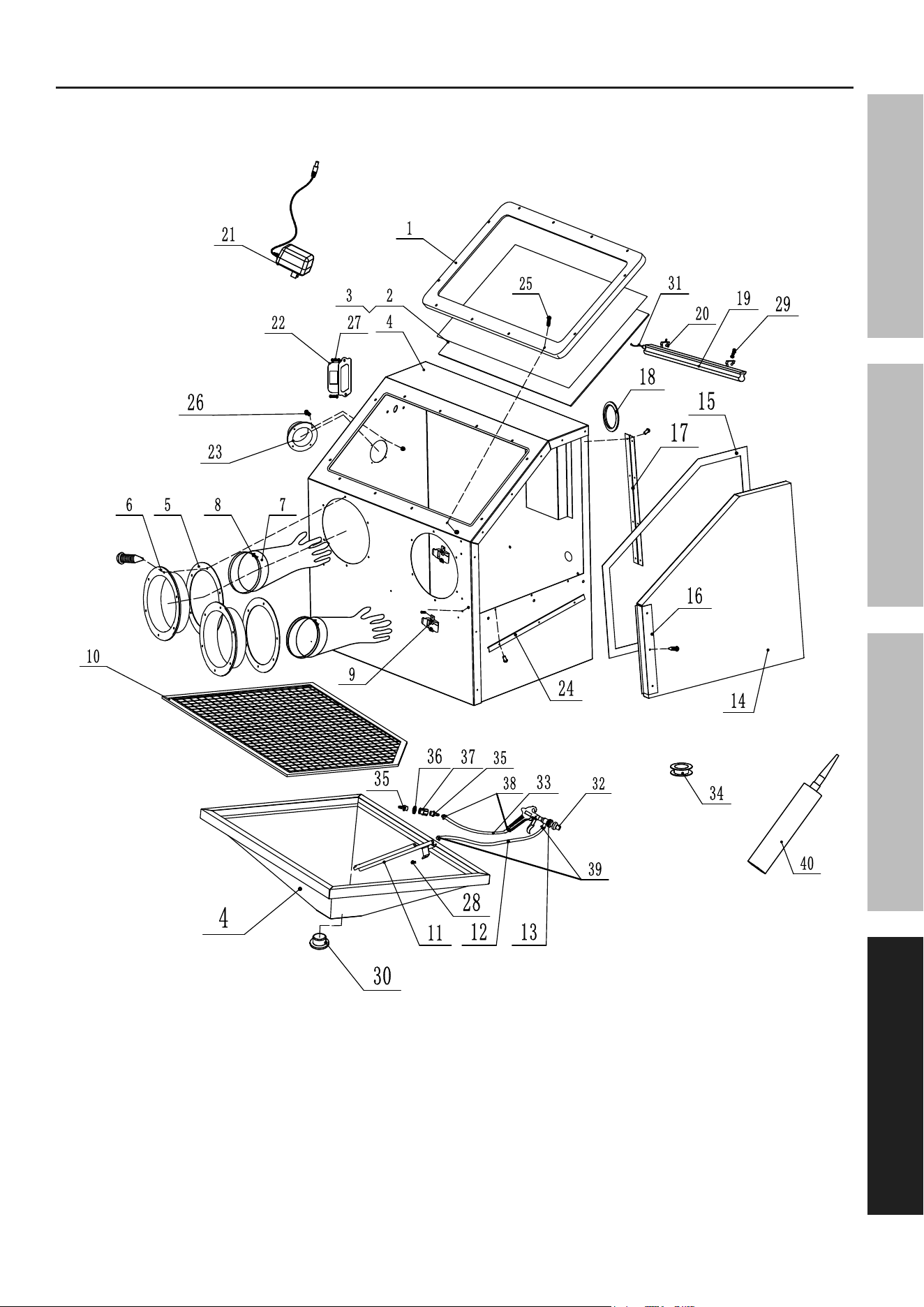
parts List - Blast cabinet
part Description Qty
1 Window Frame 1
2 Window 1
3 Window Liner 3
4 Body 1
5 Port Washer 2
6 Glove Port 2
7 Blast Glove 2
8 Glove Clamp 2
9 Door Latch 2
10 Grate 1
11 Siphon Tube 1
12 Siphon Hose 1
13 Blast Gun 1
14 Door 1
15 Sealing Strip 1
16 Door Edge Trim 1
17 Hinge 1
18 Rubber Ring 1
19 LED Lamp 1
20 Lamp Lock 2
part Description Qty
21 Transformer 1
22 Switch Box 1
23 Flange 1
24 Door Edgings 1
25 Window Frame, M5 x 25 Screw & Nut 12
26 Flange, M5 x 10 Screw & Nut 4
27 Switch Box, M5 x 8 Screw & Nut 2
28 Siphon Tube, M6 x 12 Screw & Nut 2
29 Lamp Lock, M6 x 6 Screw & Nut 2
30 Hopper Cover 1
31 Lamp Line 1
32 4.5/5/6/7mm Ceramic Nozzle 4
33 Air Hose 1
34 Teflon Tape 1
35 Thread Connector 2
36 Rubber Flat Gasket 1
37 Internal Thread Connector 1
38 Clamp Φ16‑25 2
39 Clamp Φ8‑12 2
40 Silicone Sealant 1
record product's Serial number Here:
note: If product has no serial number, record month and year of purchase instead.
note: Some parts are listed and shown for illustration purposes only, and are not available
individually as replacement parts. Specify UPC 193175471888 when ordering parts.
Page 21For technical questions, please call 1-888-866-5797.Item 59477
SaFetyOperatiOnMaintenance Setup
assembly Diagram - Blast cabinet

Page 22 For technical questions, please call 1-888-866-5797. Item 59477
SaFety OperatiOn MaintenanceSetup
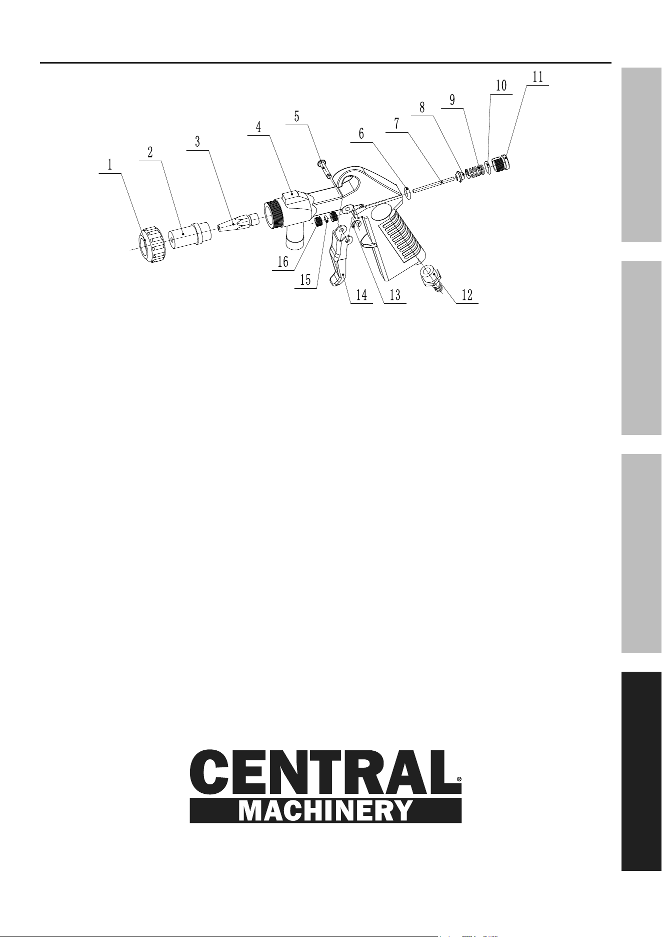
parts List - Blast Gun
part Description Qty
1A Nozzle Lock 1
2A Nozzle 4
3A Air Jet 1
4A Gun Body 1
5A Pin 1
6A O‑Ring 1
7A Round Pin 1
8A Round Pin Cover 1
part Description Qty
9A Spring 1
10A O‑Ring 1
11A Air Vent 1
12A Air Hose Connector 1
13A E‑Type Rib 1
14A Handle 1
15A O‑Ring 1
16A Screw 2
note: When ordering replacement parts from this list, the ″A″ suffix must be included in order to get the correct part.
Page 23For technical questions, please call 1-888-866-5797.Item 59477
SaFetyOperatiOnMaintenance Setup
assembly Diagram - Blast Gun

Limited 90 Day Warranty
Harbor Freight Tools Co. makes every effort to assure that its products meet high quality and durability standards,
and warrants to the original purchaser that this product is free from defects in materials and workmanship for the
period of 90 days from the date of purchase. This warranty does not apply to damage due directly or indirectly,
to misuse, abuse, negligence or accidents, repairs or alterations outside our facilities, criminal activity, improper
installation, normal wear and tear, or to lack of maintenance. We shall in no event be liable for death, injuries
to persons or property, or for incidental, contingent, special or consequential damages arising from the use of
our product. Some states do not allow the exclusion or limitation of incidental or consequential damages, so the
above limitation of exclusion may not apply to you. THIS WARRANTY IS EXPRESSLY IN LIEU OF ALL OTHER
WARRANTIES, EXPRESS OR IMPLIED, INCLUDING THE WARRANTIES OF MERCHANTABILITY AND FITNESS.
To take advantage of this warranty, the product or part must be returned to us with transportation charges
prepaid. Proof of purchase date and an explanation of the complaint must accompany the merchandise.
If our inspection verifies the defect, we will either repair or replace the product at our election or we may
elect to refund the purchase price if we cannot readily and quickly provide you with a replacement. We will
return repaired products at our expense, but if we determine there is no defect, or that the defect resulted
from causes not within the scope of our warranty, then you must bear the cost of returning the product.
This warranty gives you specific legal rights and you may also have other rights which vary from state to state.
26677 agoura road • calabasas, ca 91302 • 1-888-866-5797
