
2
CONTENTS
IMPORTANT SAFETY INFORMATION
3
PARTS
5
INSTALLATION OF FLAPS
6
EXTERNAL VENTILLATION
7
INSTALLATION
7
EXHAUST INSTALLATION
11
OPERATION
12
GREASE MESH FILTERS
12
CARBON FILTER
13
REPLACING THE BULB
14
CLEANING AND MAINTENANCE
15
TROUBLESHOOTING
16
SPECIFICATION AND SUPPORT
17
PRODUCT FICHE
18

3
IMPORTANT SAFETY INFORMATION
Please read this instruction manual carefully and retain
for future reference. It contains important information
concerning the safe operation, installation and
maintenance of the appliance.
• There must be adequate ventilation of the room when
the hood is used at the same time as appliances
burning gas or other fuels.
• This cooker hood is only designed for domestic use,
and should not be used in a commercial environment.
• Never use the hood for any purpose other than its
intended use.
• Do not check the status of the filters during operation of
the cooker hood.
• Do not touch the light bulb within 30 minutes of use.
• Do not flambé or excessively flame under the hood.
• Never leave frying food unattended as it can be a
serious fire hazard.
• If the supply cord is damaged, it must be replaced by
the manufacturer, its service agent or a similarly
qualified person in order to avoid a hazard.
• The socket outlet for the hood must be located so it is
easily accessible for the user after installation.
• Ensure the mains supply voltage corresponds with that
of the appliance.
• There is a fire risk if cleaning is not carried out in
accordance with the instructions.
• Ensure that the socket used provides adequate earthing
of the appliance, if unsure professional advice must be
sought.
• This appliance can be used by children aged from 8
years and above and persons with reduced physical,

4
sensory or mental capabilities or lack of experience and
knowledge if they have been given supervision or
instruction concerning use of the appliance in a safe
way and understand the hazards involved.
• Children must not play with the appliance.
• Cleaning and user maintenance must not be carried out
by children without supervision.
• When the hood is being maintained, cleaned or filters
changed, make sure it is switched off at the mains
supply.
• The exterior of the hood should be cleaned with mild
detergent on a warm damp sponge or cloth.
• The air must not be discharged into a flue that is used
for exhausting fumes from appliances burning gas or
other fuels.
• Regulations concerning the discharge of air have to be
fulfilled.
• The minimum distance between the supporting surface
for the cooking vessels on the hob and the lowest part
of the hood must be at least 65 cm.
• When the cooker hood is used in conjunction with
appliances supplied with energy other than electric, the
negative pressure in the room must not exceed 0,04
mbar to prevent fumes being drawn back into the room
by the cooker hood.
• Failure to install the hood in accordance with these
instructions may result in electrical hazards.
CAUTION:
Accessible parts may become hot when used with
cooking appliances.
Deep fat fryers must be continuously monitored during
use: overheated oil can burst into flames.
5
PARTS
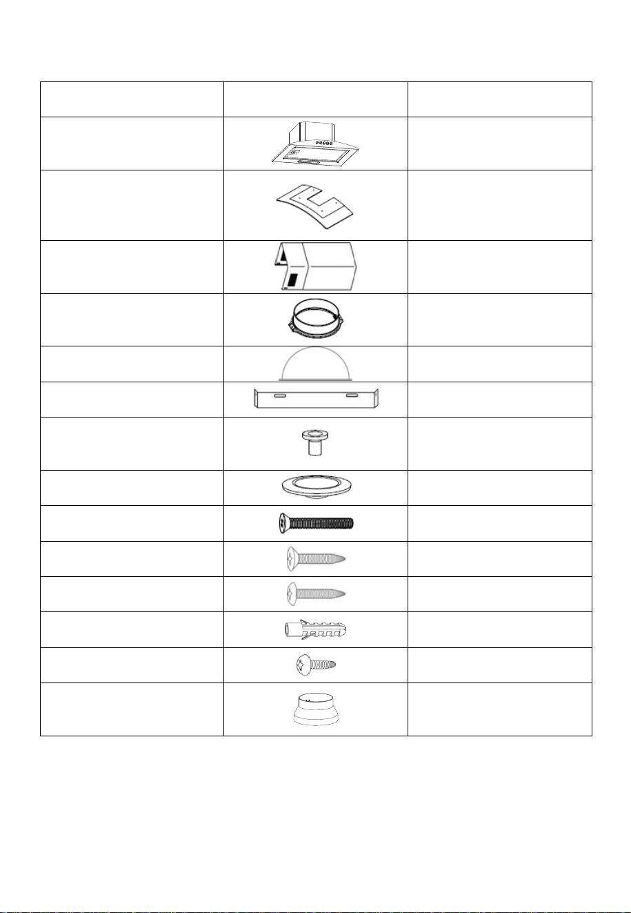
DESCRIPTION ILLUSTRATION QTY
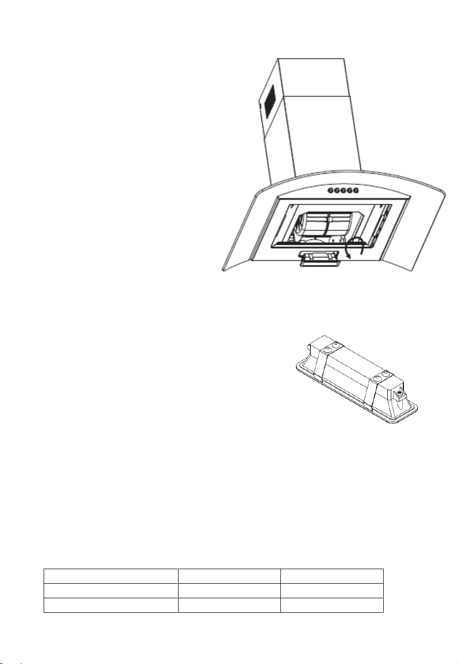
Cooker Hood 1
Glass Canopy
1
Chimney Sections (Pair) 1
Outlet 1
Air Flap 2
Chimney bracket
1
Canopy Anti vibration ring
4
Canopy Mounting washer 4
Bolt (M4*20)
4
Screw (ST4*40)
2
Screw (ST4*30)
4
Wall plug
6
Screw (ST4*8)
4
Exhaust Adaptor
1
6
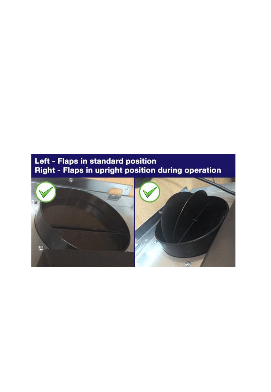
INSTALLATION OF THE FLAPS
The 2 air flaps should now be installed on the top of the unit, as access
is easier before the unit is wall mounted. The flaps should be carefully
installed, bending them slightly so the lugs at each end locate into the
holes in the outlet vent. When the unit is in operation the flaps pivot
upwards to allow airflow.
Please note: Ensure the small lugs at each end of each flap locate into
the holes on the housing and not the grooves above them.
After installing the flaps, ensure that they are able to pivot freely within
the outlet, before fixing the air outlet to the top of the unit using 2 x ST4*8
Screws.
7
OPTIONS FOR VENTILATION
This hood can be set up for either external venting or recirculation of the
air. The type of setup should be decided before commencing
installation.
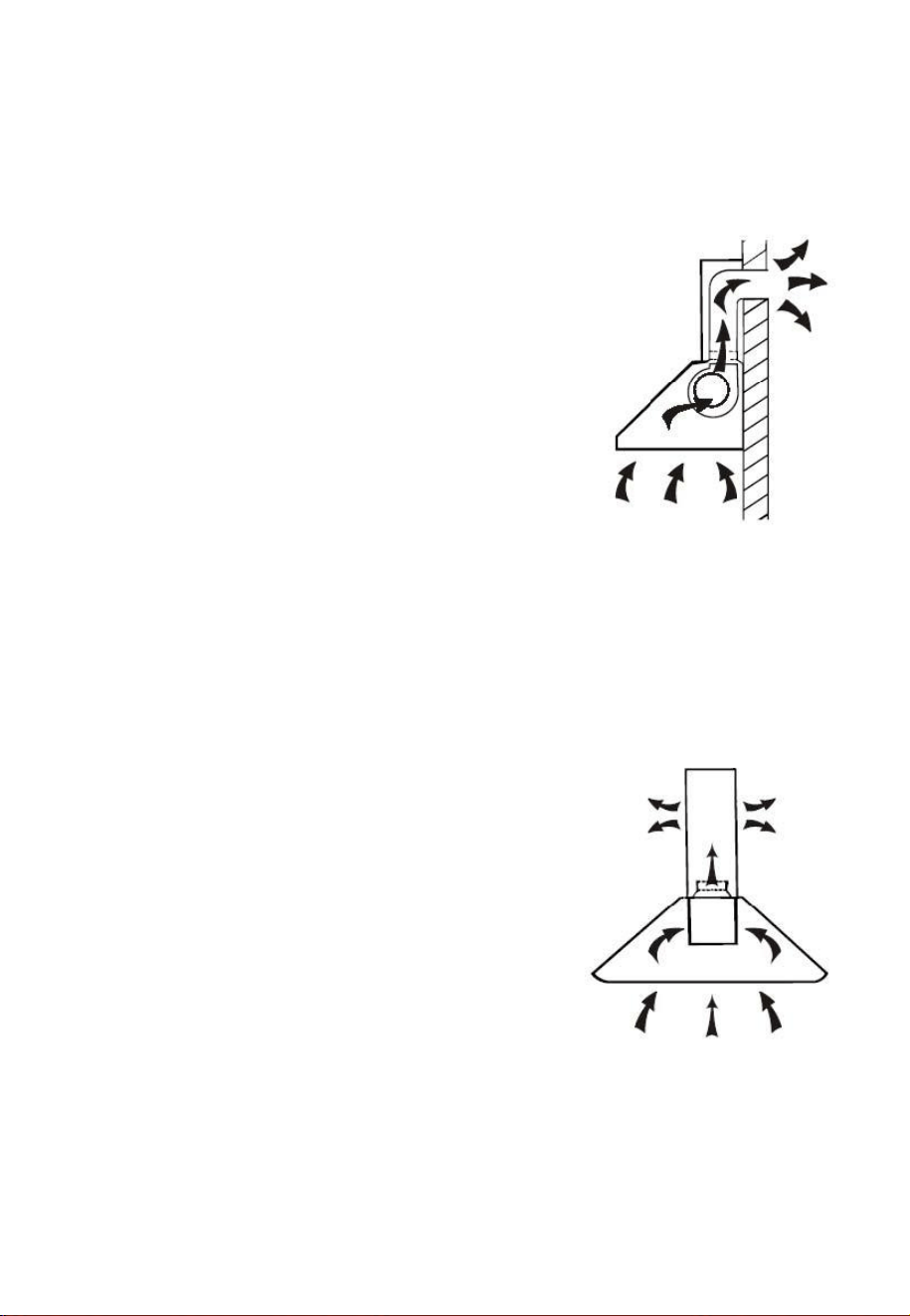
EXTERNAL VENTING
If you have an outlet leading outside, your
cooker hood can be connected as shown in the
diagram using a flexible exhaust pipe.
Alternatively, any suitable extraction duct
(enamel, aluminium, flexible pipe or
inflammable material with an interior diameter
of 120/150mm) can be used.
An adaptor is also supplied to enable you to
connect your hood to pre-existing 120mm
diameter ducting.
If this is the chosen installation method, consideration to the route of the
vent pipe should be made prior to installation.
NOTE: the performance of the hood may be affected if the diameter of
the pipe is reduced, or if the airflow is restricted.
RECIRCULATION
This cooker hood also supports the
recirculation of air once it has passed through
the filters. The filtered air is then expelled
through the vent holes in the side of the
chimney.
When setting the unit up in this configuration,
carbon filters should also be used to remove
odors from the air. Details of fitting the filters
can be found in the Carbon filter section.
When setting up for recirculation the installation instructions should be
followed, but the vent pipe should not be attached, allowing the air to be
expelled through the vents on the side of the chimney.

8
INSTALLATION
• Unpack the hood and check that all functions are working. Ensure that
the voltage (V) and the frequency (Hz) indicated on the serial plate
match the voltage and frequency at the installation site.
• Check that the area behind the installation surface is clear of any
electrical cables or pipes, etc to avoid damage when drilling.
• The surfaces of the hood can be very easily damaged during installation.
Take care with tools to protect the surfaces during installation.
• Protect the hob surface with cardboard, or similar, to prevent damage
occurring whilst the hood is being installed above.
• The manufacturer shall not be liable for any failure to observe all
safety regulations in force for the correct and normal operation of
electrical products.
• Ensure the wall is level and the installation plates are horizontal to
prevent grease from accumulating within the hood.
• Ensure the power has been turned off at the mains before starting
installation.
• Connection to the mains supply must be in an accessible location.
• You may need the following tools to complete this installation:
• Drill appropriate for your wall
• Phillips Screwdriver
• Tape Measure
• Electrical wiring must be done by a qualified professional in accordance
with all applicable codes and standards, including fire rated construction.
IMPORTANT
• Sufficient air is needed for proper combustion and exhaustion of gases
through the flue (chimney) for fuel burning equipment to prevent back
drafting. Ductless fans must always be vented to the outdoors.
• When assessing the air pressure, the entire ventilation system in the
house/apartment must be taken into account.
• All legal regulations must be observed for the conveyance of exhaust air.
If the extractor hood is used in recirculating mode with the optional
carbon filter, there are no operating restrictions.
9
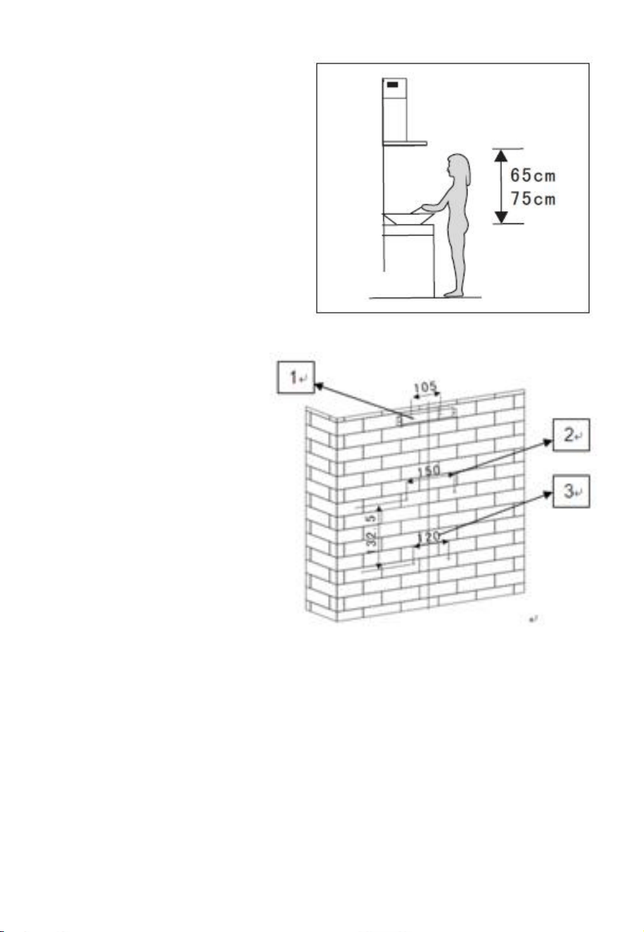
1. Before installation, ensure
you have not connected
the appliance to the
mains supply.
2. The cooker hood should
be placed at a distance of
65~75cm above the
cooking plane for best
effect.
3. After confirming the
height of the cooker
hood measure the
position of the
holes inside and
outside of the
chimney bracket for
hanging the hood.
4. Drill 4 holes, 2 for
the inner chimney
bracket and 2 for
hanging the hood, and keep the hood level.
The inner chimney bracket should be
secured at the highest point.
5. Screw two 4 x 30mm screws on the wall with wall plugs to fix the
hood, then use two 4mm x 40mm screws to fix the inner chimney
bracket.
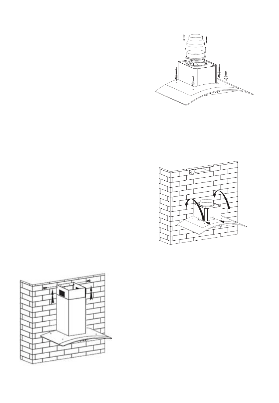
10
6. Place the glass canopy on to the
hood, aligning the screw holes.
Place the anti-vibration rings into
the 4 holes before securing the
glass canopy into place by
tightening the 4 bolts (M4*20)
through the mounting rings into
the hood.
7. Then fix the outlet on the hood
and attach the adaptor.
8. Hang the hood on the wall in the desired
final position.
9. Once the hood is positioned
correctly, fix the unit to the wall
using 2 x ST4*30 screws and wall
plugs through the fixing holes.
The fixing holes are located inside
the unit behind the grease filters.
10. Place the two chimneys together
onto the cooker hood body. Adjust
the height of the inner chimney
until a suitable height. Fix the inner
chimney to the chimney bracket
using the supplied screws
(ST4*8).
11
EXHAUST INSTALLATION
The following rules must be strictly followed to obtain optimal air
extraction:
• Keep the expansion pipe short and straight.
• Do not reduce the size or restrict expansion pipe.
• When using an expansion pipe always install the pipe pulled
taut to minimize pressure loss.
• Failure to observe these basic instructions will reduce the
performance and increase noise levels of the cooker hood.
• Any installation work must be carried out by a qualified
electrician or competent person.
• Do not connect the ducting system of the hood to any existing
ventilation system which is being used for any other appliance,
such as a warmer tube, gas tube or hot wind tube.
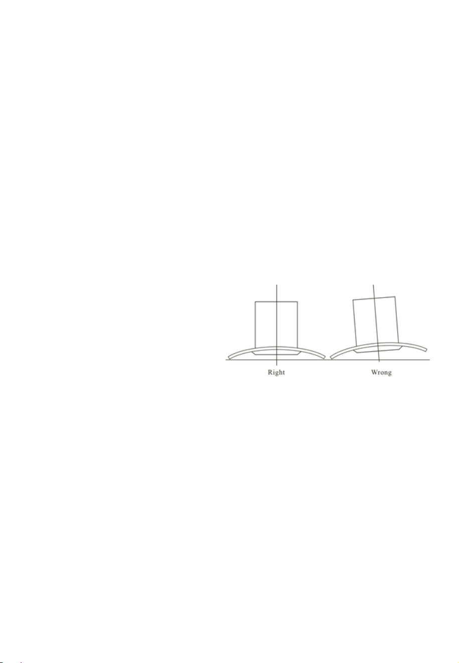
• The angle of the bend of the expansion pipe should be no less
than 120º; you must direct the pipe horizontally, or,
alternatively, the pipe should
go up from the initial point
and be led to an outer wall.
• After the installation, make
sure that the cooker hood is
level to avoid grease
collection at one end.
NOTE: Ensure the expansion pipe selected for installation
complies with relevant standards and is fire retardant.
12
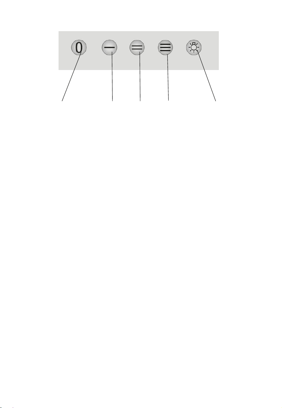
USING YOUR COOKER HOOD
STOP
Turns off the motor
LOW
Will extract at low speed
MEDIUM
Will extract at medium speed
HIGH
Will extract at high speed
LIGHTS
Turn the light on and off
GREASE MESH FILTERS
The mesh filters can be cleaned by hand. Soak them for 3 - 4 minutes
in warm water with a grease-loosening detergent. Brush gently with a
soft brush. To avoid damage, do not apply unnecessary pressure.
Leave to dry naturally out of direct sun light.
Filters should be washed separately to crockery and kitchen utensils.
it is advisable not to use rinse aid. Replacement grease filters are
available from the retailer under code: eiQGFA60 for eiQCURV60EN/
INSTALLING GREASE MESH FILTERS
1. Angle the filter into slots at the back of the hood.
2. Pull the handle of the filter.
3. Release the handle once the filter fits into a resting position.
4. Repeat for all filters.
STOP LOW MEDIUM HIGH LIGHTS ON/OFF
ENBL;eiQGFA90 for eiQCURV90EN/ENBL
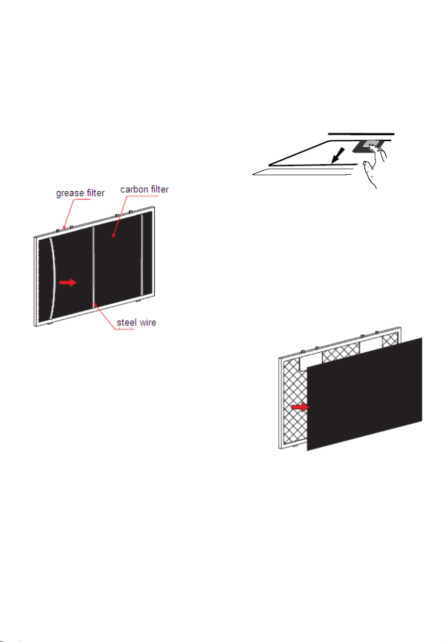
13
CARBON FILTER (Not Supplied)
Activated carbon filters can be used to trap odours. Normally the
activated carbon filter should be changed every three or six months
according to your cooking habit. Grease filters are available from the
retailer and directly from the manufacturer under stock code:
eiQCF152 for eiQCURV60EN/ENBL;eiQCF15290 for eiQCURV90EN/
ENBL. The installation procedure is as below.
1. Remove the grease filter.
2. Unclip the wire from the
reverse of the grease filter.
3. Place the new carbon filter onto the
reverse of the grease filter.
4. Fix the carbon filter with the steel wire
previously removed.
5. Reinstall the grease filter onto the appliance.
NOTE:
• Make sure the filter is securely locked. Otherwise, it may loosen and
cause injury
• When the attached carbon filter is activated, the suction power of the
hood will be lowered.
14
REPLACING THE BULB
1. Switch off the extractor
hood and ensure it is
also switched off at the
mains supply.
2. Remove the grease
filters.
3. Disconnect the wiring
connector on the lead
running from the lamp
holder.
4. Replace the holder and
lamp with an identical
unit available from the
retailer/manufacturer.
NOTE: Remember to switch on at the mains once installation is
completed and the hood has been fully reassembled.
ILCOS D code for this lamp is:
DBS-2/65-H-120/33
• Max wattage: 1×2 W
• Voltage range: AC 110-240V
NOTE: The bulb must be replaced by the
manufacturer, its service agent or similarly qualified persons.
Always switch off the electricity supply before carrying out any
operations on the appliance. When handling the bulb, make sure it is
completely cool down before any direct contact to hands.
REPLACEMENT FILTERS
Replacement filters are available both from the retailer and directly
through the manufacturer.
0RGHO
*UHDVHILOWHU
HL4&859(1(1%/
eiQGFA60
&DUERQILOWHU
eiQCF152
HL4&859(1(1%/
eiQGFA90
eiQCF15290

15
CLEANING AND MAINTENANCE
Disconnect range hood from power supply before cleaning or
servicing.
1. Clean the hood surface frequently using mild detergent and a warm
damp sponge or cloth.
2. Do not use harsh alkalis or abrasives.
3. Avoid the use of scouring powers or dishwasher compounds.
4. If the optional carbon filter is being used, these cannot be cleaned
and require replacing every 2-3 months depending on frequency of
use. They are available from the retailer who supplied your hood.
5. The stainless steel must be cleaned regularly, weekly cleaning will
yield best results. Dry with a clean soft cloth. A specialized stainless-
steel cleaning fluid may be used.
6. Ensure that wiping is done along with the grain of the stainless steel
to prevent any unsightly crisscross scratching patterns from
appearing
INFORMATION
Water must be kept away from the motor, control panel and all
electrical components.
GREASE FILTERS
It is recommended that the grease filter is cleaned every two
to three months by carrying out the following instruction:
1. Remove the grease filter from the cooker hood and wash it
in a solution of warm water and neutral liquid detergent,
leaving to soak.
2. Rinse thoroughly with warm water and allow to dry
thoroughly before refitting.
3. The metallic filter may alter in colour after several washes.
There is a fire risk if cleaning is not carried out in accordance
with the instructions.
16
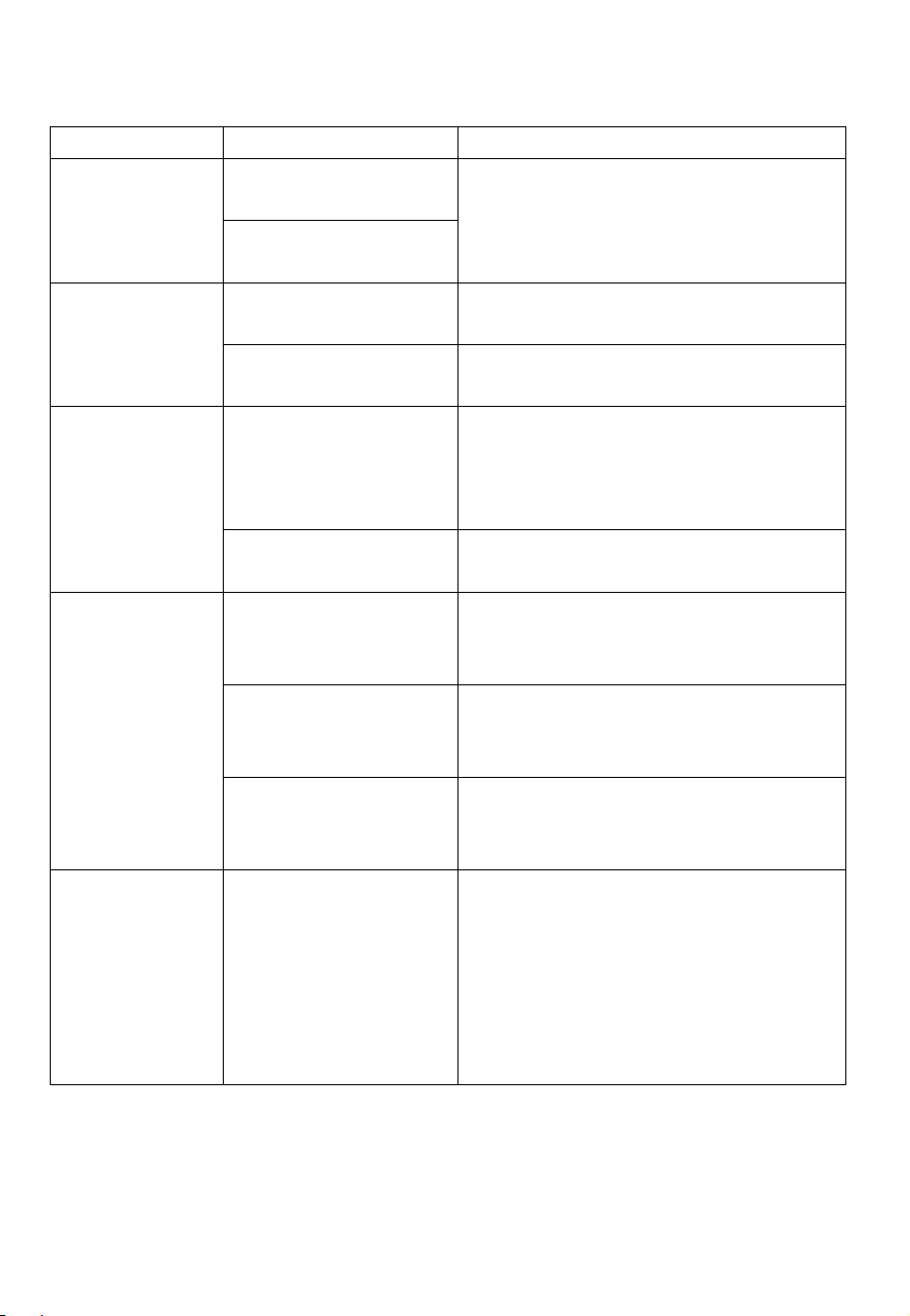
TROUBLESHOOTING
Fault
Cause
Solution
Light on, but
fan does not
work
The fan blade is
jammed.
Switch off the unit. Repair to
be carried out by qualified
service personnel only.
The motor is
damaged.
Both light
and fan do
not work
Light has blown.
Replace the lamp with correct
rating.
Power cord
loose.
Plug in to the power supply
again.
Grease or
oil leaking
from the
underside of
the hood
Outlet and/or air
ventilation
connections are
not tightly sealed
Ensure connections on the
ventilation hose are tight.
Grease filters
clogged
Wash or replace the grease
filters.
Excessive
Vibration
The fan blade is
damaged.
Switch off the unit. Repair to
be carried out by qualified
service personnel only.
The fan motor is
not fixed tightly.
Switch off the unit. Repair to
be carried out by qualified
service personnel only.
The unit is not
hung properly on
the bracket.
Take down the unit and check
whether the bracket is in
proper location.
Poor suction
performance
1 Are the grease
filters clogged?
2 Distance
between the unit
and the cooking
plane too great.
1 Clean or replace grease
filters.
2. Adjust the distance to
between 70cm and 80cm.
17
electriQ UK Support
Office hours: 9AM - 5PM Monday to Friday
0330 390 3061
www.electriQ.co.uk
Unit J6, Lowfields Business Park
Lowfields Way, Elland
West Yorkshire, HX5 9DA
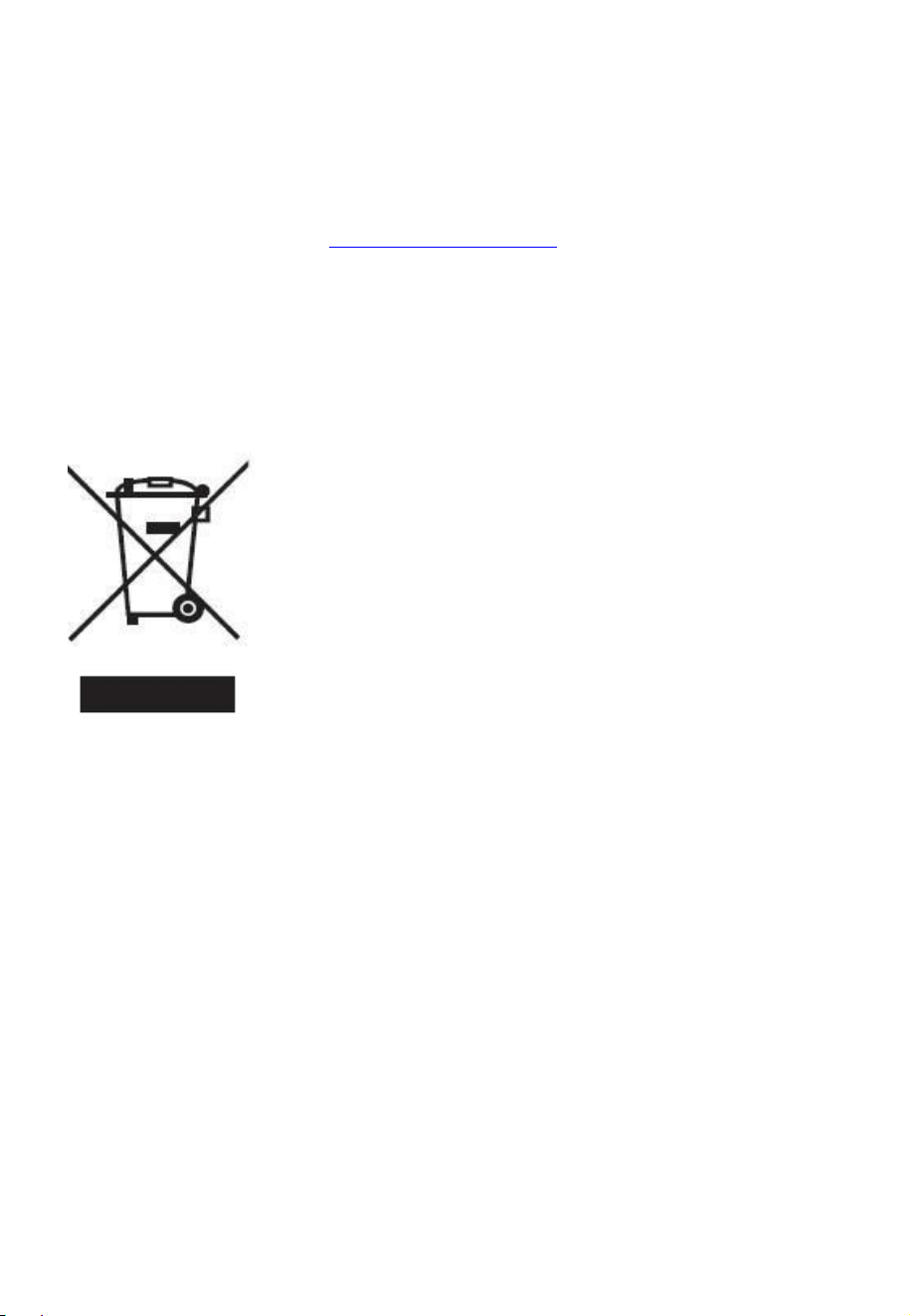
PRODUCT DISPOSAL
Do not dispose this product as unsorted municipal waste.
Collection of such waste must be handled separately as
special treatment is necessary.
Recycling facilities are now available for all customers at
which you can deposit your old electrical products.
Customers will be able to take any old electrical equipment
to participating civic amenity sites run by their local
councils. Please remember that this equipment will be
further handled during the recycling process, so please be
considerate when depositing your equipment. Please
contact the local council for details of your local household
waste recycling centres.
18
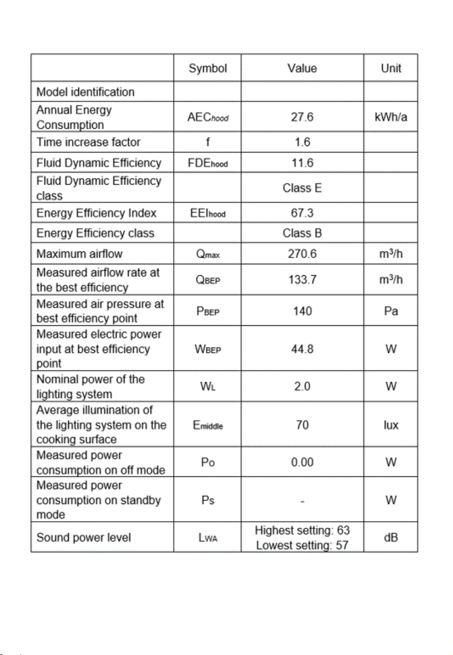
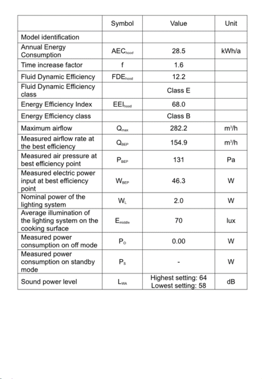
PRODUCT FICHE
eiQCURV60EN/ENBL
19
eiQCURV90EN/ENBL