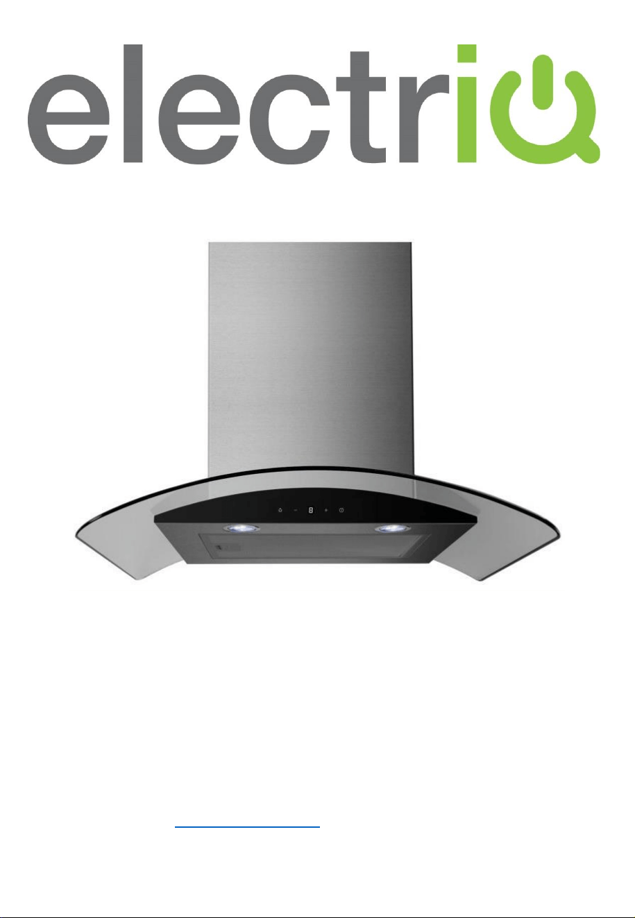
INSTALLATION AND USER MANUAL
COOKER HOOD
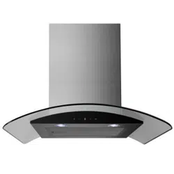
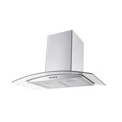
60cm Hood
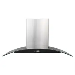
90cm Hood
Stainless Steel
eiQCURV60SCTOUCH
eiQCURV90SCTOUCH
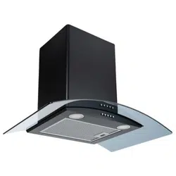
Black
eiQCURV60BLTOUCH
eiQCURV90BLTOUCH
Please read this manual before using or installing the cooker hood and
keep it safe for future reference.
Visit our page www.electriQ.co.uk for our entire range of electricals

2
CONTENTS
IMPORTANT SAFETY INFORMATION
3
PARTS
5
INSTALLATION DIAGRAM
6
OPTIONS FOR VENTILLATION
7
INSTALLATION
8
OPERATION
11
REPLACING THE BULB
12
INSTALLING THE CARBON FILTER (OPTIONAL)
13
REMOVAL AND REFITTING OF THE GLASS CANOPY
14
CLEANING AND MAINTENANCE
15
TROUBLESHOOTING
16
SPECIFICATION
17
MANUFACTURER SUPPORT
17

3
IMPORTANT SAFETY INFORMATION
Please read this instruction manual carefully and retain for future
reference. It contains important information concerning the safe
operation, installation and maintenance of the appliance.
• There must be adequate ventilation of the room when the
hood is used at the same time as appliances burning gas or
other fuels.
• This cooker hood is only designed for domestic use, and
should not be used in a commercial environment.
• Never use the hood for any purpose other than its intended
use.
• Do not check the status of the filters during operation of the
cooker hood.
• Do not touch the light bulb within 30 minutes of use.
• Do not flambé or excessively flame under the hood.
• Never leave frying food unattended as it can be a serious fire
hazard.
• If the supply cord is damaged, it must be replaced by the
manufacturer, its service agent or a similarly qualified person
in order to avoid a hazard.
• The socket outlet for the hood must be located so it is easily
accessible for the user after installation.
• Ensure the mains supply voltage corresponds with that of the
appliance.
• There is a fire risk if cleaning is not carried out in accordance
with the instructions.
• Ensure that the socket used provides adequate earthing of
the appliance, if unsure professional advice must be sought.
• This appliance can be used by children aged from 8 years
and above and persons with reduced physical, sensory or
mental capabilities or lack of experience and knowledge if
they have been given supervision or instruction concerning
use of the appliance in a safe way and understand the
hazards involved.
• Children must not play with the appliance.

4
• Cleaning and user maintenance must not be carried out by
children without supervision.
• When the hood is being maintained, cleaned or filters
changed, make sure it is switched off at the mains supply.
• The exterior of the hood should be cleaned with mild
detergent on a warm damp sponge or cloth.
• The air must not be discharged into a flue that is used for
exhausting fumes from appliances burning gas or other fuels.
• Regulations concerning the discharge of air have to be
fulfilled.
• The minimum distance between the supporting surface for
the cooking vessels on the hob and the lowest part of the
hood must be at least 65 cm.
• When the cooker hood is used in conjunction with appliances
supplied with energy other than electric, the negative
pressure in the room must not exceed 0,04 mbar to prevent
fumes being drawn back into the room by the cooker hood.
• Failure to install the hood in accordance with these
instructions may result in electrical hazards.
CAUTION:
Accessible parts may become hot when used with cooking
appliances.
Deep fat fryers must be continuously monitored during use:
overheated oil can burst into flames
5
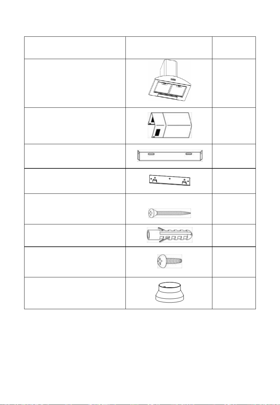
PARTS
DESCRIPTION
ILLUSTRATION
QTY
Cooker Hood
1
Chimney Sections
2
Chimney bracket
2
Hood Installation Plate
1
Screw (ST5*50)
7
Wall plug
7
Screw (ST4.2*9.5)
6
Exhaust adaptor
1
6
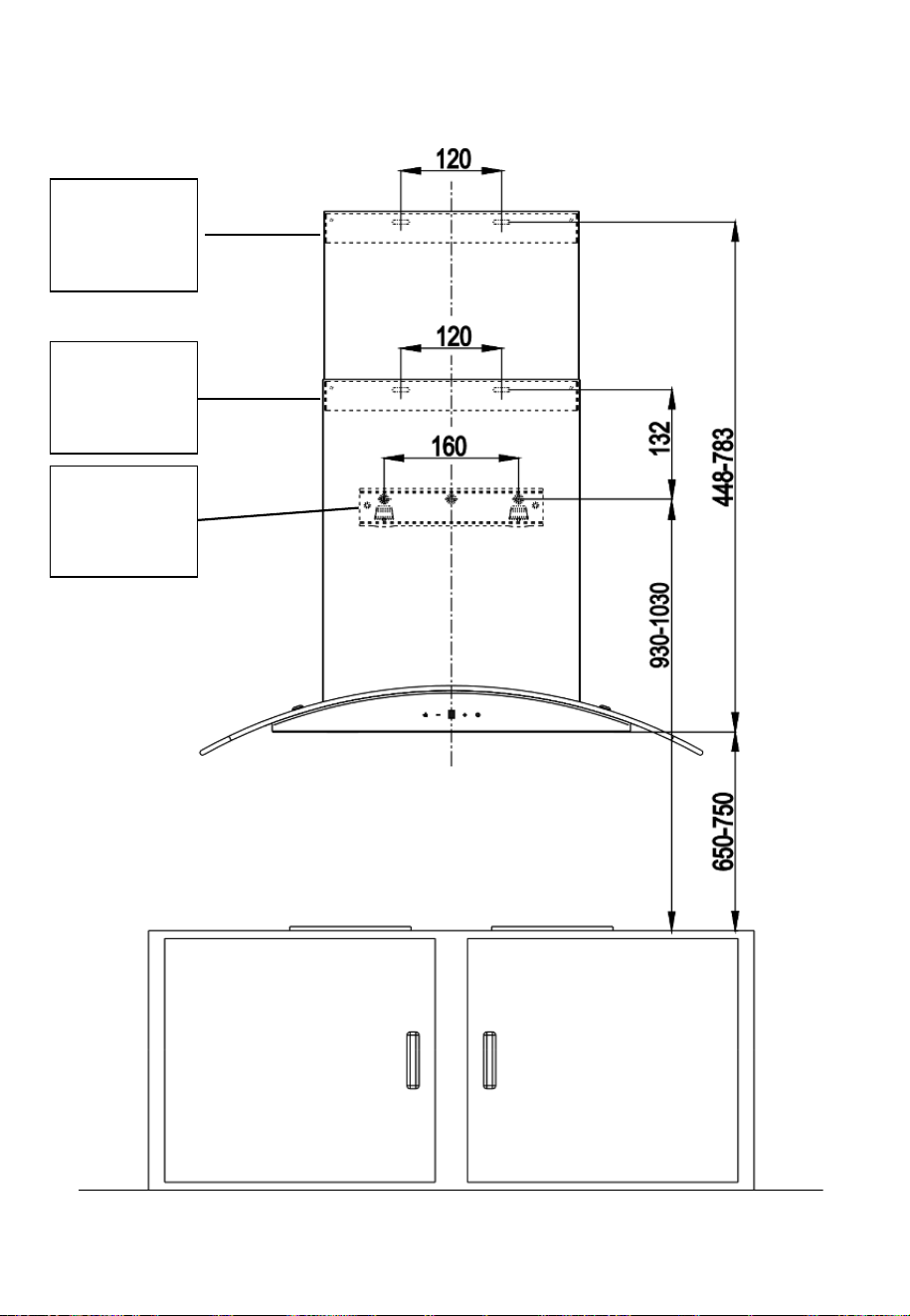
INSTALLATION DIAGRAM
Upper
Chimney
Bracket
Lower
Chimney
Bracket
Hood
Installation
Plate
7
OPTIONS FOR VENTILATION
This hood can be set up for either external venting or recirculation of the
air. The type of setup should be decided before commencing installation.
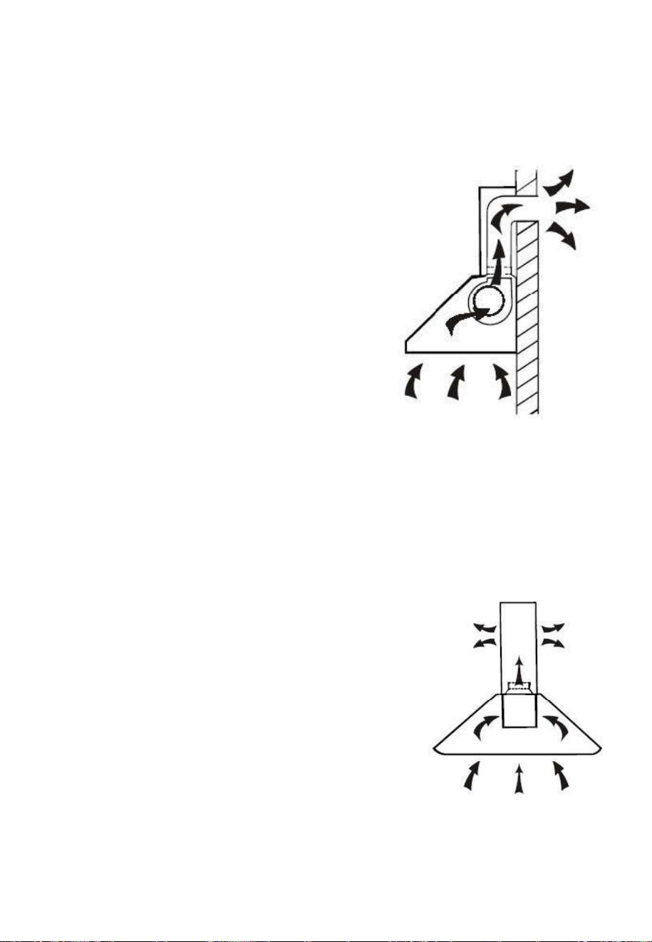
EXTERNAL VENTING
If you have an outlet to the outside, your
cooker hood can be connected as shown
in the diagram using the flexible exhaust
pipe (NOT SUPPLIED). Alternatively,
any suitable extraction duct (enamel,
aluminium, flexible pipe or inflammable
material with an interior diameter of
150mm) can be used.
An adaptor is also supplied to enable you
to connect your hood to pre-existing
120mm diameter ducting.
If this is the chosen installation method consideration to the route of the
vent pipe should be made prior to installation.
Please note: the performance of the hood may be affected if the diameter
of the pipe is reduced, or if the airflow is restricted.
RECIRCULATION
This cooker hood also supports the recirculation
of air once it has passed through the filters.
The filtered air is then expelled through the vent
holes in the side of the chimney.
When setting the unit up in this configuration,
carbon filters should also be used to remove
odours from the air. Details of sourcing and
fitting the filters can be found in the carbon filter
section of this manual.
8
INSTALLATION
BEFORE INSTALLING YOUR HOOD:
• Unpack the hood and check that all functions are working. Ensure that
the voltage (V) and the frequency (Hz) indicated on the serial plate
match the voltage and frequency at the installation site.
• Check that the area behind the installation surface to be drilled is clear
of any electrical cables or pipes, etc.
• The surfaces of the hood are very easily damaged during installation if
grazed or knocked by tools. Please take care to protect the surfaces
during installation.
• Protect the hob surface with cardboard, or similar, to prevent damage
occurring whilst the hood is being installed above.
• The manufacturer shall not be liable for any failure to observe all
safety regulations in force for the correct and normal operation of
electrical products.
• Ensure the wall is level and the installation plates are horizontal to
prevent grease from accumulating within the hood.
• Ensure the power has been turned off at the mains before starting
installation.
• Connection to the mains supply must be in an accessible location.
• You may need the following tools to complete this installation:
• Drill appropriate for your wall
• Phillips Screwdriver
• Tape Measure
• Hand Saw or Jig Saw
• Electrical wiring must be done by a qualified person in accordance with
all applicable codes and standards, including fire rated construction.
INFORMATION
• Sufficient air is needed for proper combustion and exhaustion of gases
through the flue (chimney) for fuel burning equipment to prevent back
drafting. Ductless fans must always be vented to the outdoors.
• When assessing the air pressure, the entire ventilation system in the
house/apartment must be considered.
• All legal regulations must be observed for the conveyance of exhaust
air. If the extractor hood is used in recirculating mode with the optional
carbon filter, there are no operating restrictions.
9
1. Before installation, ensure you have not connected the appliance to the
mains supply.
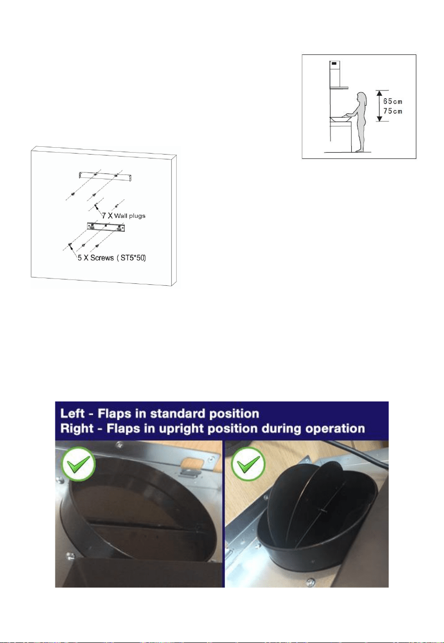
2. The cooker hood should be placed at a
distance of 65~75cm above the cooking plane
for best effect.
3. Drill all 7 holes for the hood using the
installation diagram as a guide. Use
the supplied screws (ST5 x 50mm) to
attach the hood installation plate, and
the Upper chimney bracket to the wall
in the correct position, ensuring the
plates are level.
4. The 2 air flaps should now be installed on the top of the unit, as access
is easier before the unit is wall mounted. The flaps should be carefully
installed, bending them slightly so the lugs at each end locate into the
holes in the outlet vent. When the unit is in operation the flaps pivot
upwards to allow airflow.
Please note: Ensure the small lugs at each end of each flap locate into
the holes on the housing and not the grooves above them.
10
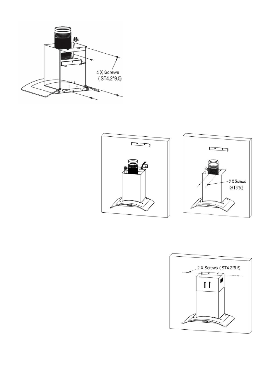
5. Slide the chimney sections onto
the hood. Fix the base of the
lower chimney section to the
hood using two ST4.2 x 9.5mm
screws (supplied)
6. Fix the lower chimney bracket
to the top of the lower chimney
using two ST4.2 x 9.5 screws
(supplied).
7. Hang the hood on the
Installation plate, and
secure to the wall
using two screws
(ST5*50) through the
lower chimney
bracket into the wall
plugs previously
inserted.
8. If the hood it to be vented externally, push an exhaust pipe onto the top
of the hood, and route it externally.
9. Slide the inner chimney up to the correct
height and fix into position on the upper
chimney bracket using the remaining two
screws (ST4.2*9.5).
11
OPERATION
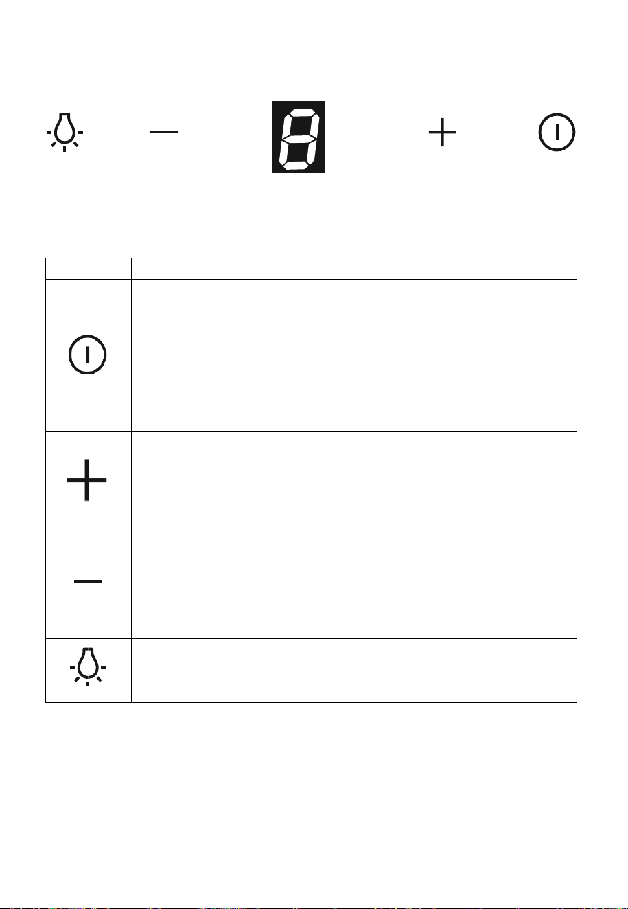
BUTTON
FUNCTION
POWER BUTTON – Allows the hood to be turned on and
off.
Please note: When turning off the fan, it will enter a 3-
minute delay to ensure all vapours and/or odours are
removed. During this the power indicator will flash. To
turn the hood off immediately during this time, press the
power button again.
INCREASE SPEED BUTTON – Press to increase the
fan speed. The current fan speed is displayed on the
panel.
1 – Low, 2 – Medium, 3 - High
DECREASE SPEED BUTTON – Press to decrease the
fan speed. The current fan speed is displayed on the
panel.
1 – Low, 2 – Medium, 3 – High
LAMP BUTTON – Turns the lights on the underside of
the hood on and off
12
REPLACING THE BULB
This hood is fitted with an LED light unit, which under normal operation
can last the lifetime of the hood. In the event that it does fail,
replacement light units are available from the same retailer the hood was
purchased from.
Before changing the fitting, ensure the hood is turned off and the power is
removed by either unplugging the unit or switching off at the pole switch
(if installed) before attempting to change the bulb. Wait until the bulb has
cooled down before commencing replacement.
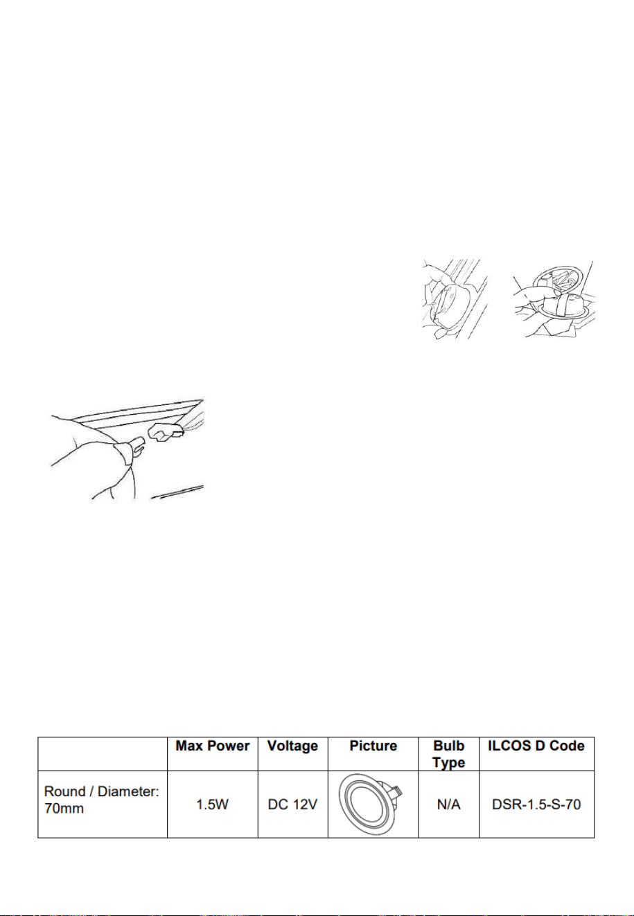
1. Remove the glass canopy from the top of the
hood, following the Removal and refitting of
the glass canopy section.
2. Locate the top of the light fitting and squeeze
the spring clips, while pushing the fitting out of the base of the hood.
3. Follow the wire from the light unit
and find the power connector on the
lead.
4. Disconnect the power connector
from it, ensuring the light fitting is not
allowed to fall from the unit
5. Replace with a new light unit, which after connecting the electrical
connection, should be pushed into position on the base of the hood.
6. Refit the glass canopy.
Important
• If a bulb is found to be defective, it should be replaced
immediately.
• Always switch off the electricity supply before carrying out any
operations on the appliance. When handling the bulb, make sure it
has completely cooled down before any direct contact to hands.
13
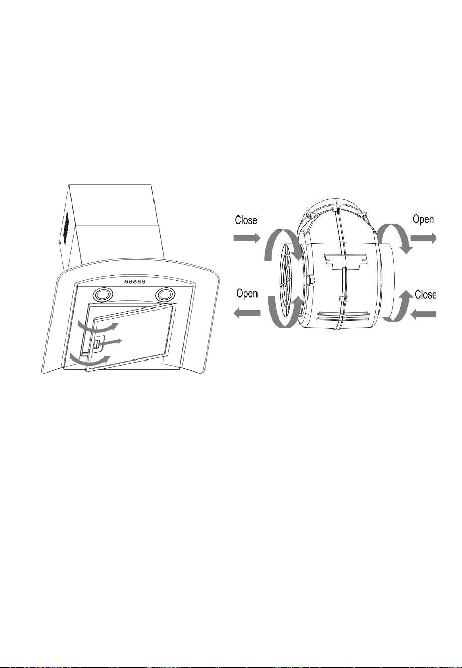
INSTALLING THE CARBON FILTER (OPTIONAL)
1. Remove the grease filters from the underside of the hood.
2. The carbon filters are located at either end of the motor.
TO FIT: Locate the filter on the peg on the side of the motor. Rotate the
filter clockwise onto the motor housing;
TO REMOVE: Rotate the filter anti-clockwise until it is unscrewed.
Warning: The carbon filter cannot be washed or recycled. It should be
replaced after approximately 2-3 months of use.
When the activated carbon filters are attached, the suction power will be
reduced.
Note: The optional carbon filter is available from the hood
supplier/manufacturer under the following stock code: eiQMIDCARBON
14
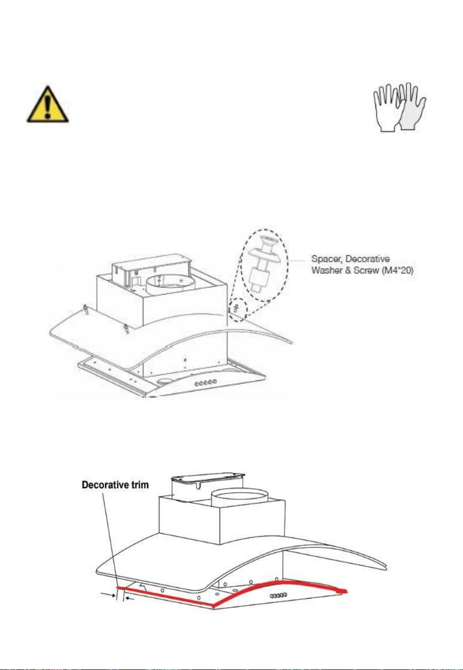
REMOVAL AND REFITTING OF THE GLASS
CANOPY
WARNING: Components within the appliance may have
sharp edges. When attempting to remove or refit the
glass, gloves should be worn to avoid scratches and
cuts.
The glass canopy is held into position using four screws, spacers and decorative
washers. Remove the four screws, spacers and decorative washers from the
glass canopy, ensuring the canopy is suitably supported. Two people should
then lift the canopy off the hood, retaining the fittings removed for re fitting.
Refitting is the reverse of removal. Before refitting the hood, please ensure the
decorative trim is correctly located, and has not become detached or displaced
during disassembly.
15
CLEANING AND MAINTENANCE
Disconnect range hood from power supply before cleaning or
servicing.
1. Clean the hood surface frequently using mild detergent and a
warm damp sponge or cloth.
2. Do not use harsh alkalis or abrasives.
3. Avoid the use of scouring powers or dishwasher compounds.
4. If the optional carbon filter is being used, these cannot be
cleaned and require replacing every 2-3 months depending
on frequency of use. They are available from the retailer who
supplied your hood.
Information
Cleaning water must be kept away from the motor, control switch
and all electrical components.
GREASE FILTERS
It is recommended that the grease filter is cleaned every two to
three months by carrying out the following instruction:
1. Remove the grease filter from the cooker hood and wash it in
a solution of warm water and neutral liquid detergent, leaving
to soak.
2. Rinse thoroughly with warm water and allow to dry thoroughly
before refitting.
3. The metallic filter may alter in colour after several washes.
There is a fire risk if cleaning is not carried out in accordance
with the instructions.
Replacement grease filters are available under the following
codes:
HOOD
GREASE FILTER
60cm Hoods
eiQM60CGFILTER
90cm Hoods
eiQM60CGFILTER
16
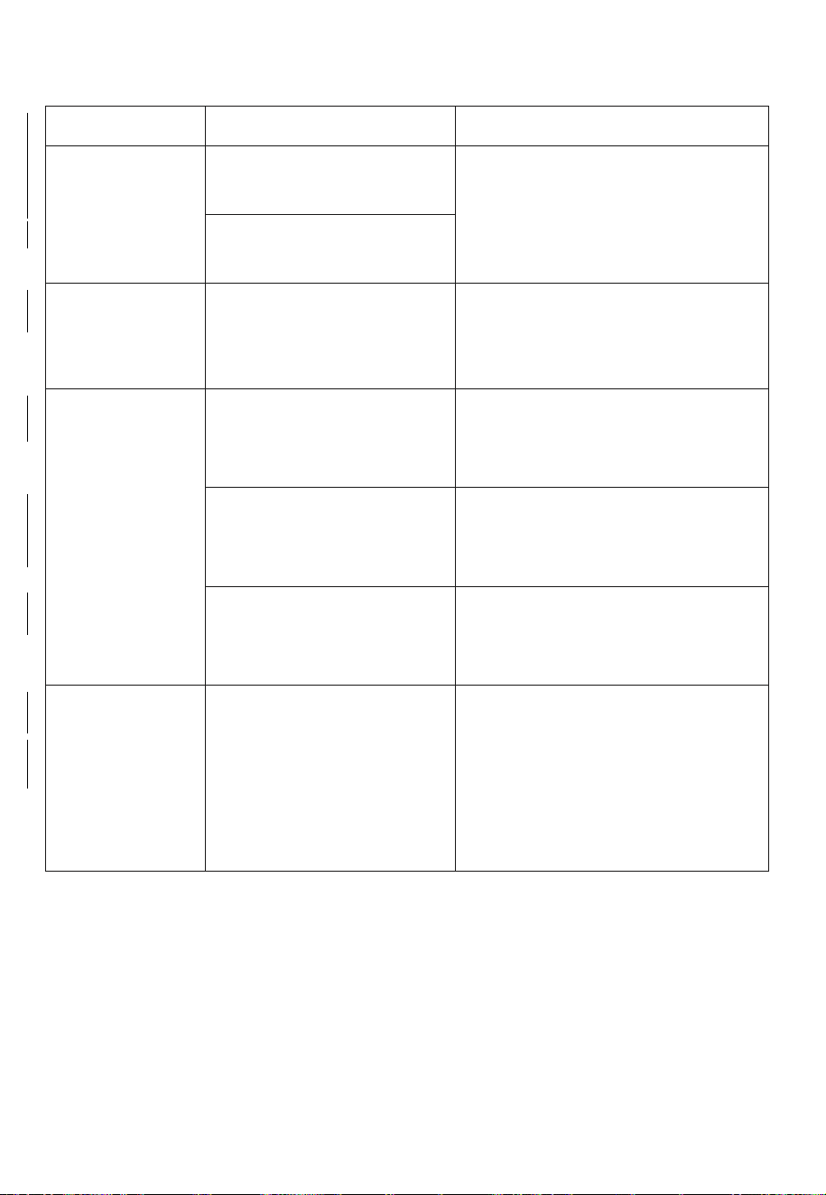
TROUBLESHOOTING
Fault
Cause
Solution
Light on, but
fan does not
work
The fan blade is
jammed.
Switch off the unit. Repair to
be carried out by qualified
service personnel only.
The motor is
damaged.
Both light
and fan do
not work
Power cord loose
Plug in to the power supply
again.
Excessive
Vibration
The fan blade is
damaged.
Switch off the unit. Repair to
be carried out by qualified
service personnel only.
The fan motor is not
fixed tightly.
Switch off the unit. Repair to
be carried out by qualified
service personnel only.
The unit is not hung
properly on the
bracket.
Take down the unit and
check whether the bracket is
in proper location.
Suction
performance
not good
1. Grease filters
clogged
2. Distance between
the unit and the
cooking plane too
great.
1 Clean or replace grease
filters.
2 Adjust the distance to
between 70cm and 80cm.
17
SPECIFICATION
Voltage
220-240V~50Hz
Rated Power
108W
Lighting Power
2 X 1.5W
Motor Power
105W
Diameter of air tube
150mm
Air flow
423.6m3/h
Noise
≤65 dB
The following shows how to reduce total environmental impact (e.g.
energy use) of the cooking process).
(1) Install the cooker hood in a proper place where there is efficient
ventilation.
(2) Clean the cooker hood regularly so as not to block the airway.
(3) Remember to switch off the cooker hood light after cooking.
(4) Remember to switch off the cooker hood after cooking.
MANUFACTURER SUPPORT
www.electriQ.co.uk
Unit J6, Lowfields Business Park
Lowfields Way, Elland
West Yorkshire, HX5 9DA
Telephone: 0330 390 3061
Office Hours: 9:00am to 5:00pm Monday to Friday
ENVIRONMENTAL PROTECTION
Waste electrical products should not be disposed of
with household waste. Please recycle where facilities
exist. Check with your Local Authority or retailer for
recycling advice.
INFORMATION FOR DISMANTLING
Do not dismantle the appliance in a way which is not shown in the user
manual. The appliance could not be dismantled by user. At the end of
life, the appliance should not be disposed of with household waste.
Check with your Local Authority or retailer for recycling advice.
18
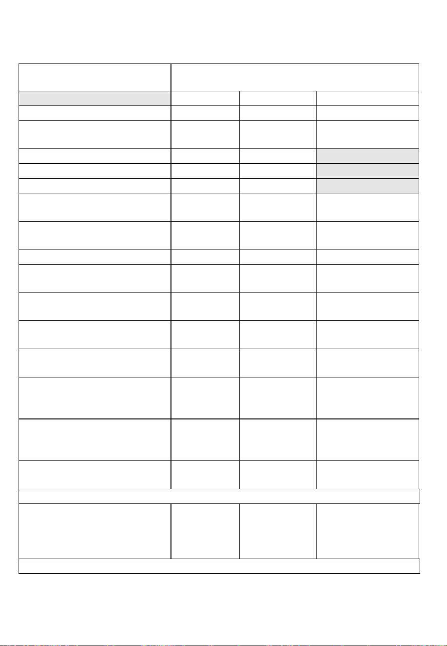
ENERGY EFFICIENCY INFORMATION FOR
DOMESTIC RANGE HOODS
Model Identification
eiQCURV60SCTOUCH eiQCURV60BLTOUCH
eiQCURV90SCTOUCH eiQCURV90BLTOUCH
Symbol
Value
Unit
Annual Energy Consumption
AEChood
53.2
kWh/A
Standard Annual Energy
Consumption
SAEChood
65.0
kWh/a
Time increase factor
F
1.6
Fluid Dynamic Efficiency
FDEhood
11.0
Energy Efficiency Index
EEIhood
81.8
Measured air flow rate at
best efficiency point
QBEP
244.2
m
3
/h
Measured air pressure at
best efficiency point
PBEP
142
Pa
Maximum air flow
Qmax
423.6
m
3
/h
Measured electric power
input at best efficiency point
WBEP
87.4
W
Nominal power of the
lighting system
WL
1.5W x 2
W
Measured power of the
lighting system
WL
3.0
W
Measured value of the
Lighting Efficiency
LEhood
59
Lux/W
Average illumination of the
lighting system on the
cooking surface
Emiddle
177
lux
Measured power
consumption in standby
mode
Ps
0.49
W
Measured power
consumption off mode
Po
--
W
Tested according to EN 50564:2011
Sound power level
LWA
Minimum
speed:57
Maximum
speed: 65
dB
Tested according to EN 60704-2-13:2011, EN 60704-1:2010 + A11:2012