26
57
27
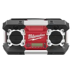
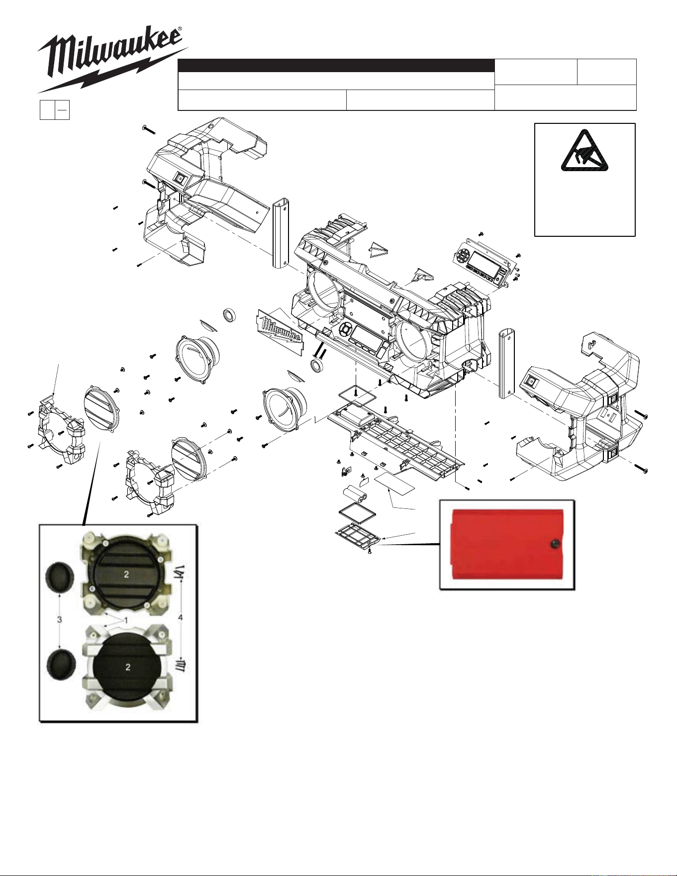
2790-20
JOBSITE RADIO
July 2013
FIG. NOTES
57 A clean, dry surface is essential for proper performance for
any adhesive system. The area intended for application of
any adhesive label or nameplate must be prepared by
cleaning with isopropyl alcohol. The solvent is to be
applied with a clean, lint free applicator and the surface
allowed to dry before applying the label or nameplate.
54-49-2791
REVISED BULLETIN
SERVICE PARTS LIST
BULLETIN NO.
WIRING INSTRUCTION
DATE
CATALOG NO.
SPECIFY CATALOG NO. AND SERIAL NO. WHEN ORDERING PARTS
SERIAL
NUMBER
MILWAUKEE ELECTRIC TOOL CORPORATION
13135 W. LISBON RD., BROOKFIELD, WI 53005
Drwg. 2
EXAMPLE:
Component Parts (Small #)
Are Included When Ordering
The Assembly (Large #).
0
00
C33B
SEE PAGE 3
FIG. PART NO. DESCRIPTION OF PART NO. REQ.
26 43-40-0675 Frame Grill Kit (1)
27 22-68-0280 Battery Cover with Screw (1)
57 12-20-1600 Service Nameplate Kit (1)
ATTENTION
OBSERVE PRECAUTIONS
FOR HANDLING
ELECTROSTATIC
SENSITIVE
DEVICES
FRAME-GRILL KIT
No. 43-40-0675
Kit includes:
1. Left and right plastic frames
2. Inner metal grills (assembled to
plastic frames as shown in picture)
3. Tweeter grills
4. Eight screws to secure the plastic
frames to radio
BATTERY COVER
No. 22-68-0280
Includes:
1. LR6 (AA) battery cover
2. Screw
3. Lock washer
54-49-2790
61
63
(1 per side)
62
(1 per side)
64
(2 per side)
65
(4 per side)
61 62 63
64 65 66
60
Items 62 & 63
are to be inserted
in the outside hole
(on both sides)
under the top
radio cover
66
FIG. PART NO. DESCRIPTION OF PART NO. REQ.
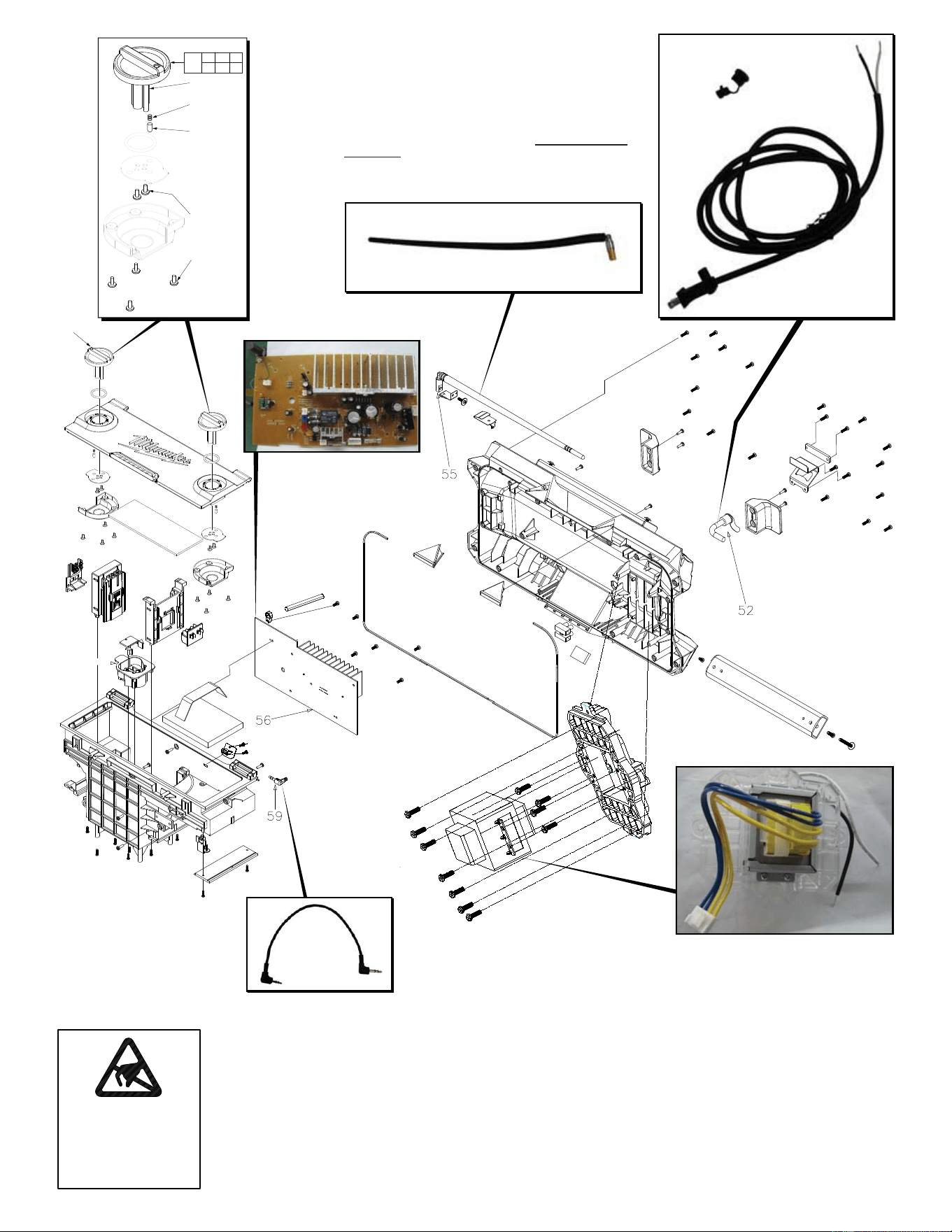
50 23-81-0626 Transformer (1)
52 22-64-0985 Cordset (1)
55 42-09-0290 Antenna Assembly (1)
56 22-09-1231 Power PCB Assembly (1)
59 42-44-0225 Auxiliary Input Cable (1)
60 14-46-2790 Locking Knob Kit (1)
61 --------------- Locking Knob - Right (1)
62 --------------- Detent Pin (2)
63 --------------- Detent Spring (2)
64 --------------- Screw (4)
65 --------------- Screw (8)
66 --------------- Locking Knob - Left (1)
ATTENTION
OBSERVE PRECAUTIONS
FOR HANDLING
ELECTROSTATIC
SENSITIVE
DEVICES
TRANSFORMER
No. 23-81-0626
CORDSET
No. 22-64-0985
1. 18/2 Cord
2. Cord clamp
POWER PCB ASSEMBLY
No. 22-09-1231
1. PCB with AM antenna
(AM antenna not shown
in picture)
FM ANTENNA ASSEMBLY
No. 42-09-0290
NOTE: When removing the antenna for replacement,
care must be taken not to lose the 2 small washers
and screw that came with the old antenna. Reuse
those parts when installing the new antenna. Washers
should be placed on each side of antenna before
securing with screw.
AUXILIARY INPUT CABLE
NO. 42-44-0225
LOCKING KNOB KIT
No. 14-46-2790
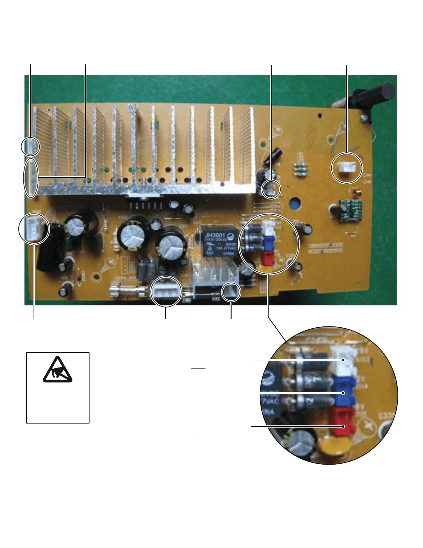
Display Ribbon
Connector
Auxilary Input
Connector
‘AA’ Battery
Connector
Antenna
Connector
Speaker
Connector
Transformer
Connector
12V Auxilary
Output Connector
Connector ports on PCB Assembly are color coded
to correspond with the colored wire of the three
different voltage wire harnesses.
White 28 volt connector
for 28 volt harness with
White and black wires
Blue 12 volt connector
for 12 volt harness with
Blue and black wires
Red 18 volt connector
for 18 volt harness with
Red and black wires
ATTENTION
OBSERVE PRECAUTIONS
FOR HANDLING
ELECTROSTATIC
SENSITIVE
DEVICES