2590-20
12 VOLT RADIO
Oct. 2012
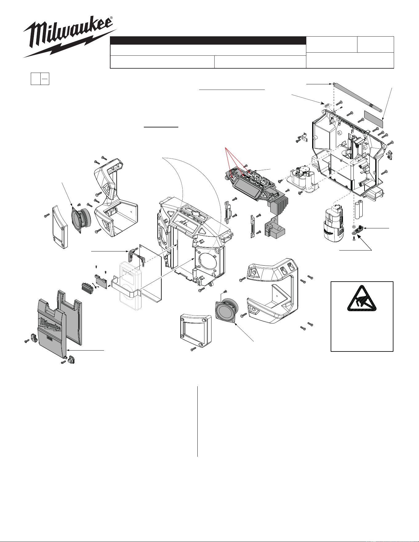
FIG. PART NO. DESCRIPTION OF PART NO. REQ.
1 42-09-1020 Antenna (1)
2 23-45-2050 Speaker Kit (1)
3 31-15-2175 Door Kit (1)
4 22-09-0580 PC Board Kit (1)
5 42-44-0225 Aux Input Cable (1)
6 12-20-2125 Service Nameplate Kit (1)
7 23-81-0700
Wall Transformer / AC Adapter (Not Shown)
(1)
8 31-15-0880 Battery Cover (1)
FIG. NOTES
6 A clean, dry surface is essential for proper performance for any
adhesive system. The area intended for application of any adhesive
label or nameplate must be prepared by cleaning with isopropyl
alcohol. The solvent is to be applied with a clean, lint free applicator
and the surface allowed to dry before applying the label or name
plate.
54-49-2590
REVISED BULLETIN
SERVICE PARTS LIST
BULLETIN NO.
WIRING INSTRUCTION
DATE
CATALOG NO.
SPECIFY CATALOG NO. AND SERIAL NO. WHEN ORDERING PARTS
SERIAL
NUMBER
MILWAUKEE ELECTRIC TOOL CORPORATION
13135 W. LISBON RD., BROOKFIELD, WI 53005
Drwg. 2
EXAMPLE:
Component Parts (Small #)
Are Included When Ordering
The Assembly (Large #).
0
00
C22A
1
2
2
3
4
5
8
Run a very thin bead of rubber
cement on the round rim of the
inside front housing of the radio
where the speakers are seated
prior to installing
new speakers.
6
ATTENTION
OBSERVE PRECAUTIONS
FOR HANDLING
ELECTROSTATIC
SENSITIVE
DEVICES
SEE BACK PAGE
NOTE:
When removing Antenna (1) for replacement, care must be
taken not to lose the 3 small washers and screw that came
with the old antenna. Reuse those parts when installing the
new antenna. Washers can be stacked together and placed
on either side of antenna before securing with screw.
NOTE:
Reuse the existing screw and
fi ber washers if the Battery
Cover (8) is being replaced.
NOTE: Rubber button covers
are not components of the PC
Board Kit #4 and are not avail-
able for replacement.
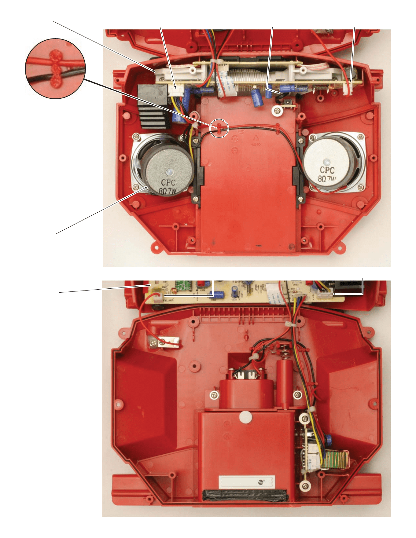
PC Board Kit
22-09-0580
Speaker Kit
23-45-2050
PC Board Kit
22-09-0580
FRONT RADIO HOUSING
BACK RADIO HOUSING
Aux Input Connector
(Located behind capacitor)
Antenna Connector
Speaker Connector
Speaker Connector
Antenna Connector
NOTE:
As part of the assembly
process, tops of wire trap
posts are slightly melted over
to secure wires.
When replacing Speaker Kit
or PC Board Kit, side cutters
or a small grinder can be
used to open the trapping
posts to free the old wires.
Install new service kits and
route wires as shown. Secure
the wires with a dab of RTV
adhesive at the trap locations.