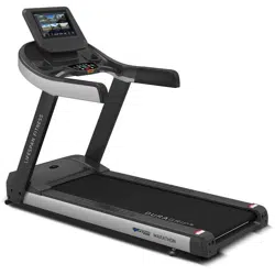
Tempest Commercial Treadmill
NOTE:
Product may vary slightly from the item pictured due to model upgrades. This manual may be subject to updates or changes.
Up to date manuals are available through our website at www.lifespanfitness.com.au
Read all instructions carefully before using this product.
Retain this owner’s manual for future reference.
IMPORTANT
All nuts and bolts are to be checked and tightened on a regular basis. This includes pedals and
other moving parts. Failure to do so may cause damage to your threads and void your warranty.
USER MANUAL
Find the
Digital Manual
Online

2
TABLE OF
CONTENTS
I. Important Safety Instructions . . . . . . . . . . . . . . . . . . . . . . . . . . . . . . . 03
II. Important Electrical Information . . . . . . . . . . . . . . . . . . . . . . . . . . . . 05
III. Important Operating Instructions . . . . . . . . . . . . . . . . . . . . . . . . . . . 06
IV. Assembly Instructions . . . . . . . . . . . . . . . . . . . . . . . . . . . . . . . . . . . . . . . 07
V. How to Move the Treadmill . . . . . . . . . . . . . . . . . . . . . . . . . . . . . . . . . . . 16
VI. Operation Guide . . . . . . . . . . . . . . . . . . . . . . . . . . . . . . . . . . . . . . . . . . . . . . 17
VII. Exercise Guide . . . . . . . . . . . . . . . . . . . . . . . . . . . . . . . . . . . . . . . . . . . . . . . . 20
VIII. Maintenance Instructions . . . . . . . . . . . . . . . . . . . . . . . . . . . . . . . . . . . . 22
IX. Exploded Diagram . . . . . . . . . . . . . . . . . . . . . . . . . . . . . . . . . . . . . . . . . . . . 24
X. Parts List . . . . . . . . . . . . . . . . . . . . . . . . . . . . . . . . . . . . . . . . . . . . . . . . . . . . . . 26
XI. Warranty . . . . . . . . . . . . . . . . . . . . . . . . . . . . . . . . . . . . . . . . . . . . . . . . . . . . . . 31
| TABLE OF CONTENTS

3
I. IMPORTANT SAFETY
INSTRUCTIONS
WARNING: Read all instructions before using this treadmill.
It is important your treadmill receives regular maintenance to prolong its useful life. Failing to
regularly maintain your treadmill may void your warranty.
DANGER
To reduce the risk of electric shock disconnect your treadmill from the electrical outlet prior to
cleaning and/or service work.
DO NOT USE AN EXTENSION CORD:
DO NOT ATTEMPT TO DISABLE THE GROUNDED PLUG BY USING IMPROPER ADAPTERS OR IN ANY
WAY MODIFY THE CORD SET.
• Install the treadmill on a flat level surface with access to a 220-240 volt (50/60Hz), grounded outlet.
• Do not operate treadmill on deeply padded, plush or shag carpet. Damage to both carpet and
treadmill may result.
• Do not block the rear of the treadmill. Provide a minimum of 1 metre clearance between the rear of the
treadmill and any fixed object.
• Place your unit on a solid, level surface when in use.
• When running, make sure the plastic clip is fastened on your clothing. It is for your safety, should you
fall or move too far back on the treadmill.
• Keep hands away from all moving parts.
• Never operate the treadmill if it has a damaged power cord or plug. When damaged, these must be
replaced by the manufacturer, its service agent or similarly qualified persons in order to avoid a
hazard.
• Keep the cord away from heated surfaces.
• Do not operate where aerosol spray products are being used or where oxygen is being administered.
Sparks from the motor may ignite a highly gaseous environment.
• Never drop or insert any object into any openings.
IMPORTANT SAFETY INSTRUCTIONS |

4
• The treadmill is intended for in-home use only and is not suitable for commercial environments.
• To disconnect, turn all controls to the off position, remove the safety key, and then remove the plug
from the outlet.
• The pulse sensors are not medical devices. Various factors, including the user’s movement, may
affect the accuracy of heart rate readings. The pulse sensors are intended only as exercise aids in
determining heart rate trends in general.
• Use the handrails provided; they are for your safety.
• Wear proper shoes. High heels, dress shoes, sandals or bare feet are not suitable for use on your
treadmill. Quality athletic shoes are recommended to avoid leg fatigue.
• Before undertaking any type of exercise program, it is recommended that you consult a doctor.
• Injuries to health may result from incorrect or excessive training.
• This appliance is not intended for use by persons (including children) with reduced physical, sensory
or mental capabilities, or lack of experience and knowledge, unless they have been given supervision
or instruction concerning use of the appliance by a person responsible for their safety.
• WARNING: Heart rate monitoring systems may be inaccurate. If you feel faint stop exercising
immediately.
• Children should not be allowed on or around the equipment, even when not in use.
• Children should be supervised to ensure that they do not play with this machine.
• Loose-fitting clothing or jewellery that could become an entanglement hazard should not be worn.
• Training shoes should be worn when using the equipment.
• Equipment must be used on a level and stable surface.
• All fixings should be checked before the equipment is used.
• All literature relating to the use of the equipment should be retained for future reference.
• Recommended operating temperature: 5-40°C.
Remove the safety key after use to prevent unauthorized
treadmill operation.
| IMPORTANT SAFETY INSTRUCTIONS
5
II. IMPORTANT ELECTRICAL
INFORMATION
This treadmill requires the right power source in order to properly operate. For your safety, as well as
the safety of others, please verify that the power source is correct before plugging the equipment. Any
incorrect power source could cause significant damage to the equipment and/or user.
WARNING!
This product must be grounded. Grounding provides the least resistance for electrical current and will
reduce the risk of electric shock. The plug must be plugged into an appropriate outlet that is properly
installed and grounded in accordance with all local codes and ordinances. Ensure that the product is
connected to an outlet which contains the same configuration as the plug. Do not use an adaptor for
this product.
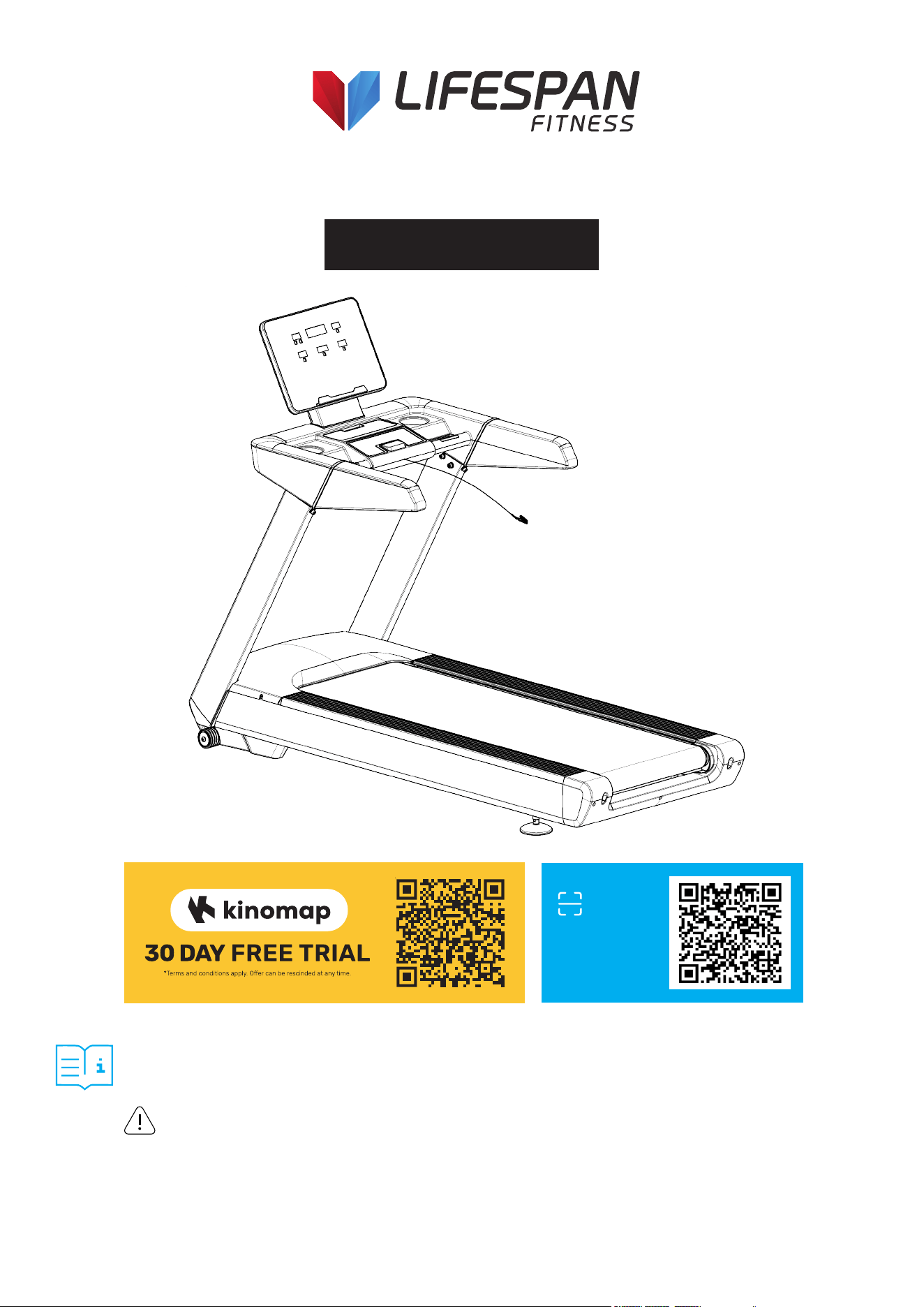
This product is for use on a nominal circuit and has a grounding plug that looks like the plug illustrated
in sketch A. Make sure that the product is connected to an outlet having the same configuration as the
plug. No adapter should be used with this product.
GROUNDING METHODS:
Improper connection of the equipment-grounding conductor can result in risk of electric shock. Check
with a certified electrician if you are in doubt as to whether the product is properly grounded. Do not
modify the plug provided with the product. If it will not fit the outlet, have a proper outlet installed by an
electrician.
DANGER
1. NEVER use a ground fault circuit interrupt (GFCI) wall outlet with this treadmill. Route the power cord
away from any moving part of the treadmill including the elevation mechanism and transport wheels.
2. NEVER operate the treadmill using a generator or UPS power supply.
3. NEVER remove any cover without first disconnecting power.
4. NEVER expose the treadmill to rain or moisture. This treadmill is not designed for use outdoors, near
pools or in any other high humidity environment.
WARNING!
IMPORTANT ELECTRICAL INFORMATION |

6
III. IMPORTANT OPERATING
INSTRUCTIONS
• Understand that changes in speed and incline do not occur immediately. Set your desired speed on
the computer console and release the adjustment key. The computer will obey the command
gradually.
• Use caution while participating in other activities while walking on your treadmill, such as watching
television, reading, etc. These distractions may cause you to lose balance or stray from walking in the
centre of the belt; which may result in serious injury.
• This unit starts with at a very low speed. It is recommended to stand on the side rails and only step
on the treadmill as it is moving on a slow speed. This will prolong the life of your motor and run the
belt smoothly.
• In order to prevent losing balance and suffering unexpected injury, never mount or dismount the
treadmill while the belt is moving at high speeds.
• Always hold on to handrail while making control changes.
• A safety key is provided with this machine. Removing the safety key will stop the walking belt
immediately; the treadmill will shut off automatically. Inserting the safety key will reset the display.
• Do not use excessive pressure on console control keys. They are precision set to function properly
with little finger pressure.
• Replace any defective components immediately. The machine must be kept out of use until repaired.
• Belt wear-in period: all treadmills make a certain type of thumping noise due to the belt riding over
the rollers, especially new treadmills. This noise will diminish over time, although may not completely
go away. The belt will stretch over time, causing it to ride smoother over the rollers.
| IMPORTANT OPERATING INSTRUCTIONS
7
IV. ASSEMBLY INSTRUCTIONS
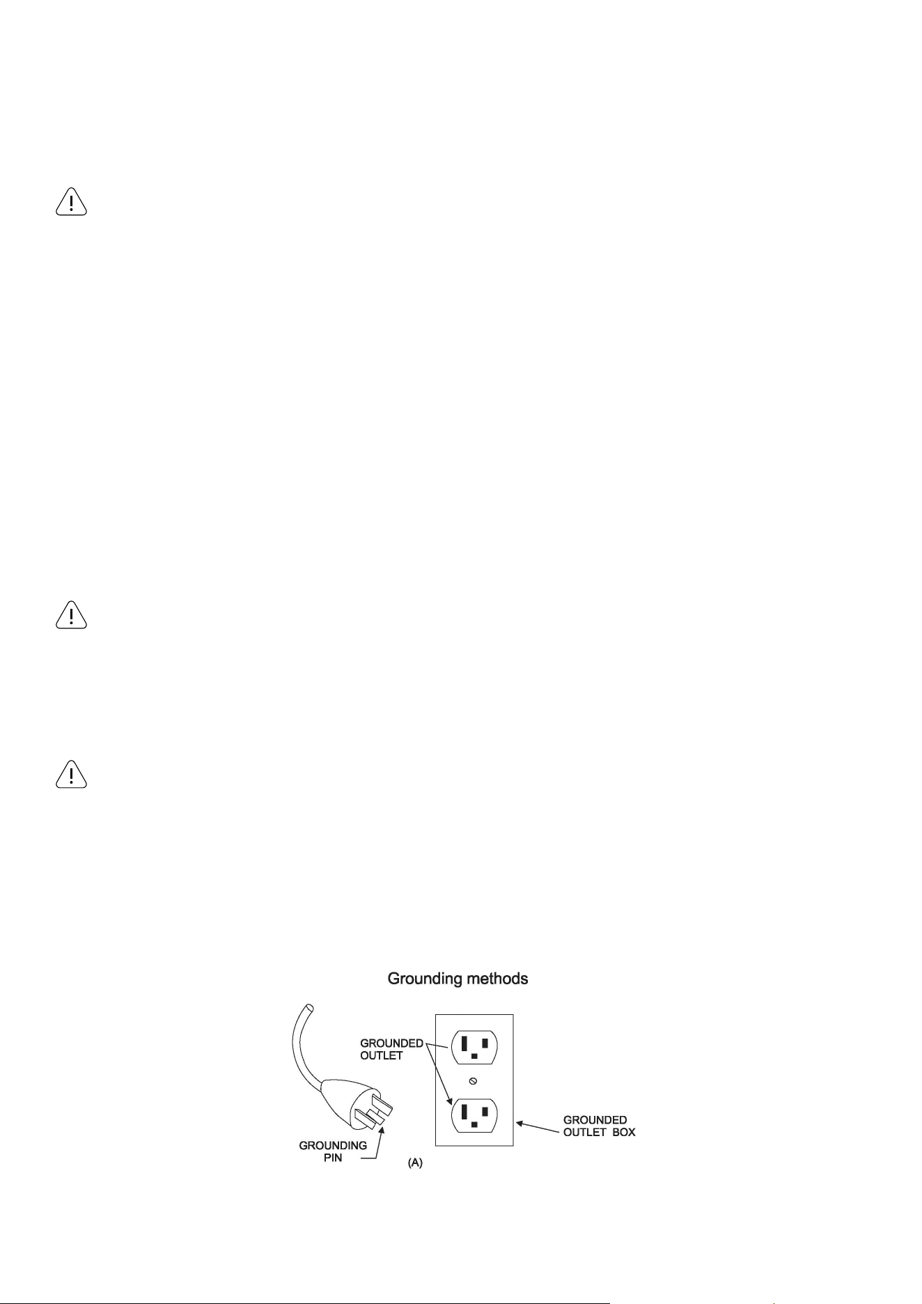
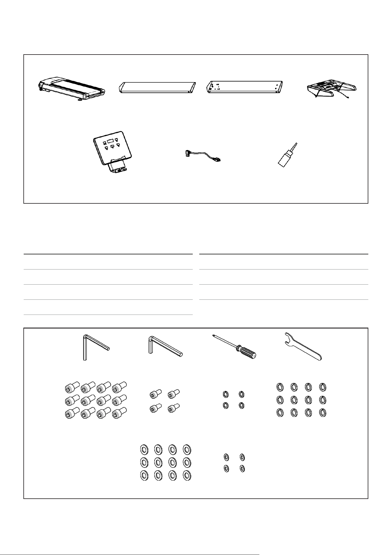
PARTS LIST
A B C D
E E22 T01
No. Description Qty
A Main Frame 1
B Left Upright Tube 1
C Right Upright Tube 1
D
Console Frame
1
No. Description Qty
E Console 1
E22 Power Wire 1
T01 Silicon Oil 1
B08 6# (x1) B09 8# (x1) B10 6*125 (x1) B11 19# (x1)
D06 M10*20 (x12) D12 M8*15 (x4)
D31 Ø8 (x4)
D33 Ø10 (x12)
D32 Ø10 (x12)
D34 Ø8 (x4)
ASSEMBLY INSTRUCTIONS |
8
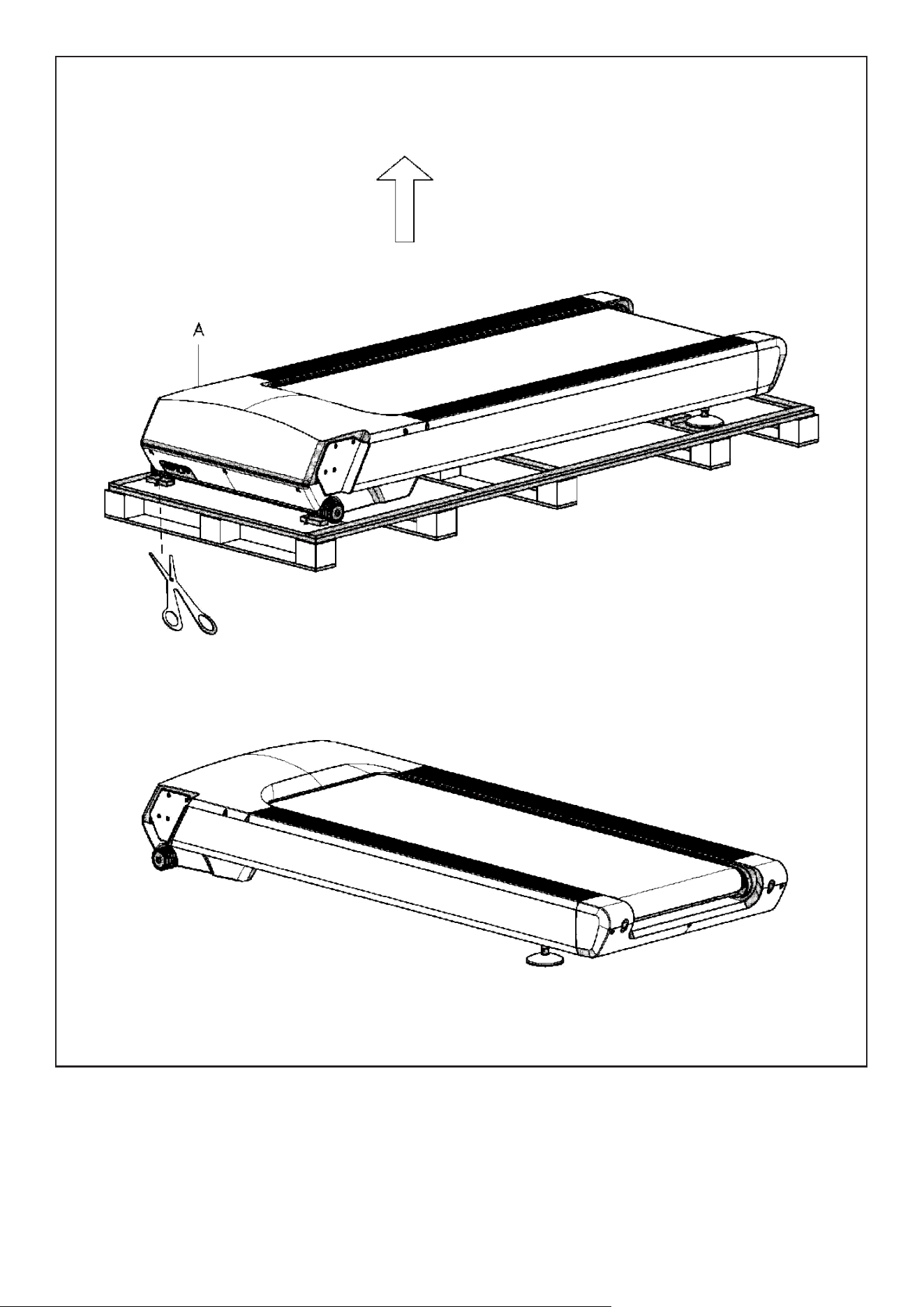
Open the carton and remove the contents. Place the Main Frame on level ground, ensure that you have a
work area that is clean and has adequate space.
STEP 1
| ASSEMBLY INSTRUCTIONS
9
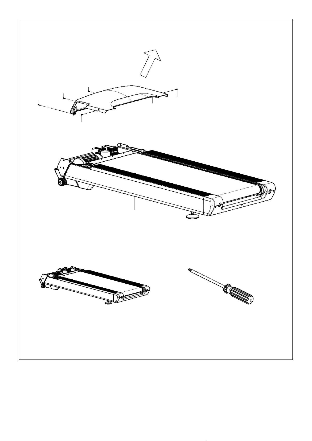
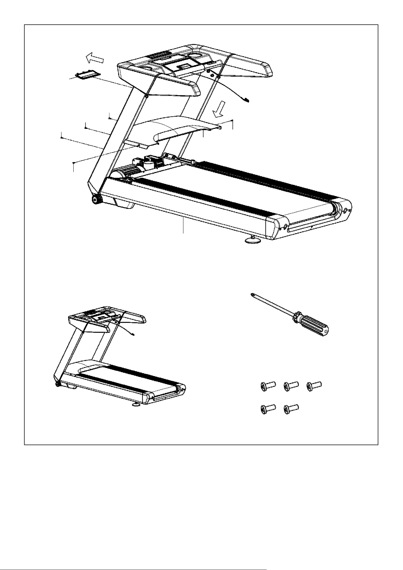
Loosen the Bolt (No. D16) on the Motor top cover (No. C01) by using Cross screwdriver (No. B10).
Set aside the cover and the screws for re-installation later.
STEP 2
D16
D16
D16
D16
D16
C01
A
B10 6*125 (x1)
ASSEMBLY INSTRUCTIONS |
10
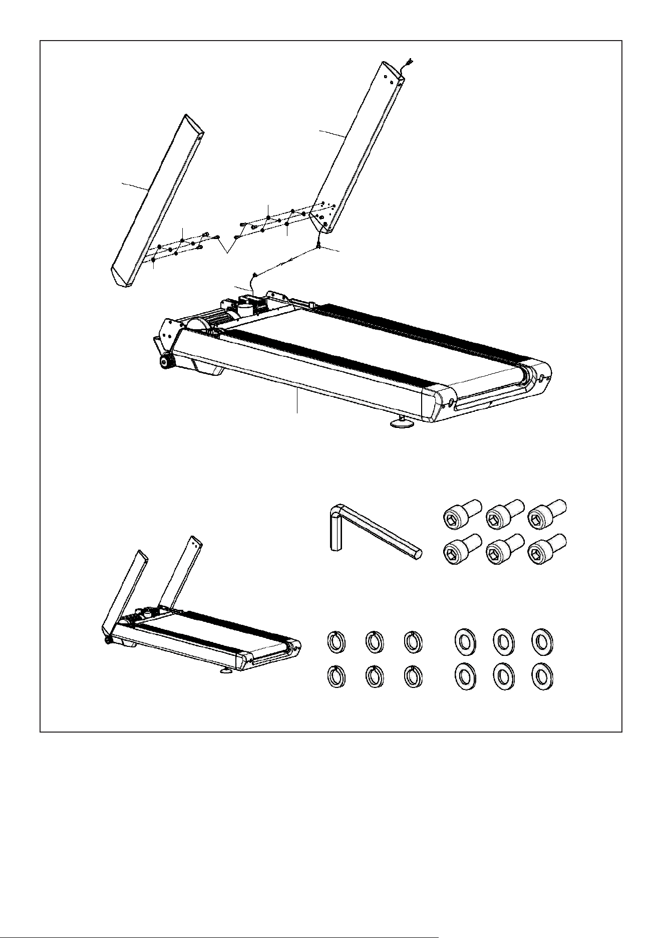
1. Connect the wire from Right upright tube (No. C) (E07) and Main base (No. A) (E08) as pictured.
2. Support the Left & Right Upright Tubes (No. B & No. C) with your hands to prevent them from falling.
3. Attach the Left & Right Upright Tubes (No. B & No. C) to the Base Frame (No. A) by using 6x Bolts
(No. D06), 6x Washers (No. D32) and 6x Washers (No. D33). Secure by using #8 Allen Wrench (No. B09).
STEP 3
D32
D32
B
C
D33
D33
D06
E08
E07
A
B09 8# (x1) D06 M10*20 (x6)
D32 Ø10 (x6) D33 Ø10 (x6)
| ASSEMBLY INSTRUCTIONS
11
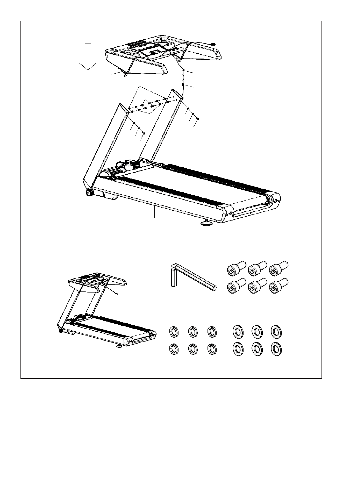
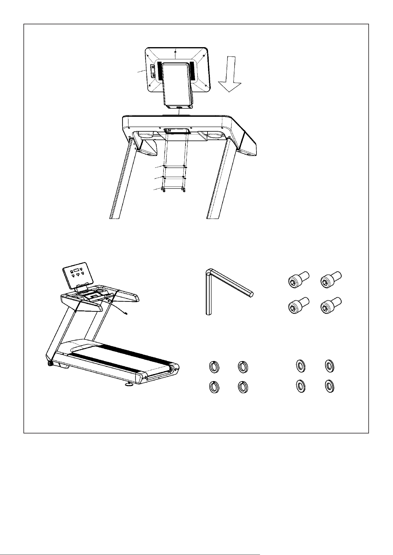
1. Connect the wire from Right upright tube (No. C) (E07) and Console base (No. D) (E06).
2. Attach the Left & Right Upright Tubes (No. B & No. C) to the Console base (No. D) by using 6x Bolts
(No. D06), 6x Washers (No. D32) and 6x Washers (No. D33). Secure by using #8 Allen Wrench (No. B09).
STEP 4
D
D33
E06
E07
D06
D32
D33
D32
D06
D33
D32
D06
A
B09 8# (x1) D06 M10*20 (x6)
D32 Ø10 (x6) D33 Ø10 (x6)
ASSEMBLY INSTRUCTIONS |
12
1. Attach the Bolt (No. D16) to the Motor top cover (No. C01) by using Cross screwdriver (No. B10).
2. Put out the Console screw cover (No. C19) from underneath the Console base (No. D).
STEP 5
C19
D16
D16
D16
D16
D16
C01
A
B10 6*125 (x1)
D16 M5*12 (x5)
| ASSEMBLY INSTRUCTIONS
13
Attach the Console (No. E) to the Console base (No. D) by using 4x Bolts (No. D12), 4x Washers (No. D31)
and 4x Washers (No. D34). Secure by using #6 Allen Wrench (No. B08).
STEP 6
E
D34
D31
D12
B08 6# (x1) D12 M8*15 (x4)
D31 Ø8 (x4) D34 Ø8 (x4)
ASSEMBLY INSTRUCTIONS |
14
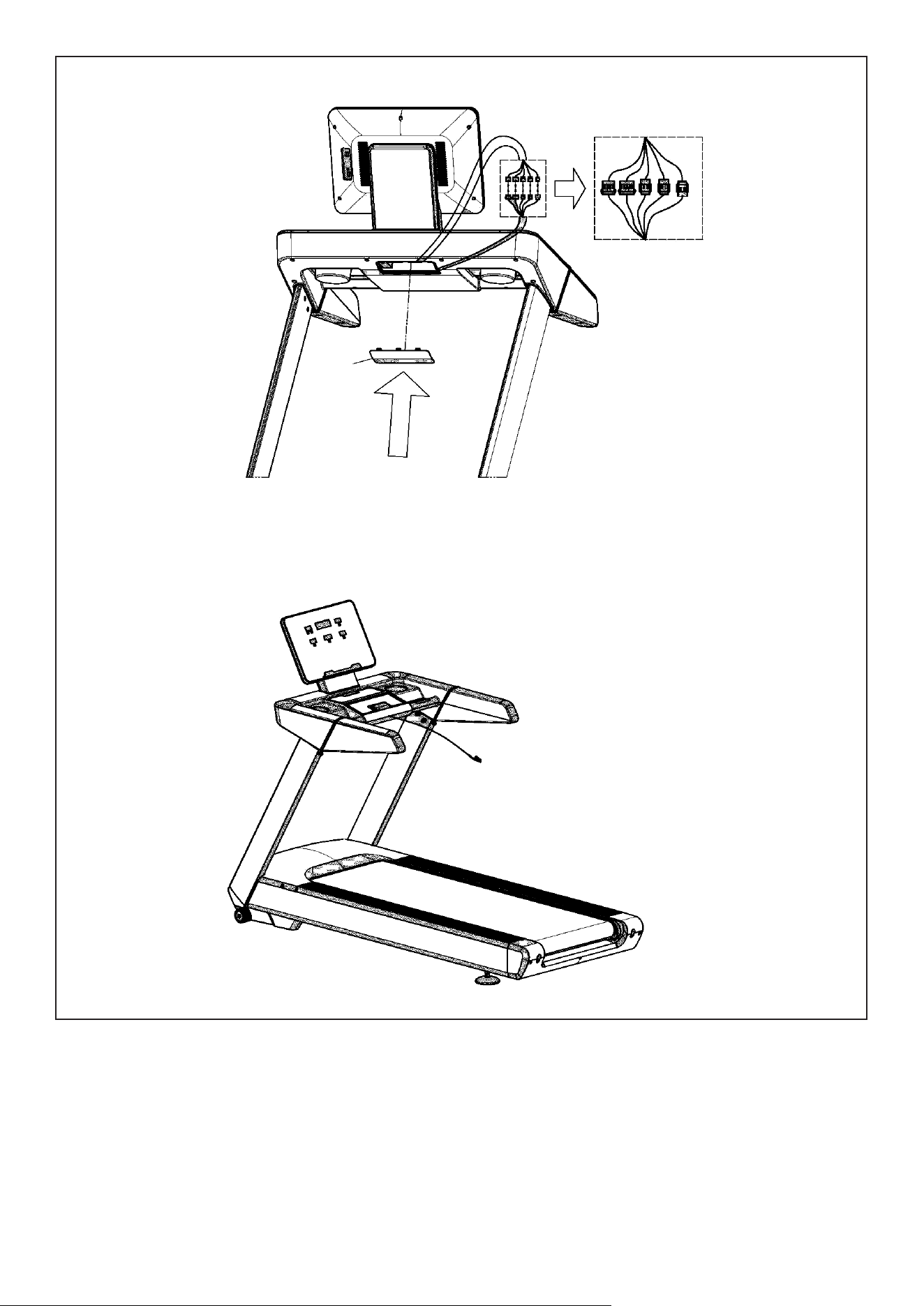
1. Connect the wire as above.
2. B. Attach the Console screw cover (No. C19) back to the Console base (No. D).
The assembly is complete!
STEP 7
C19
| ASSEMBLY INSTRUCTIONS
15
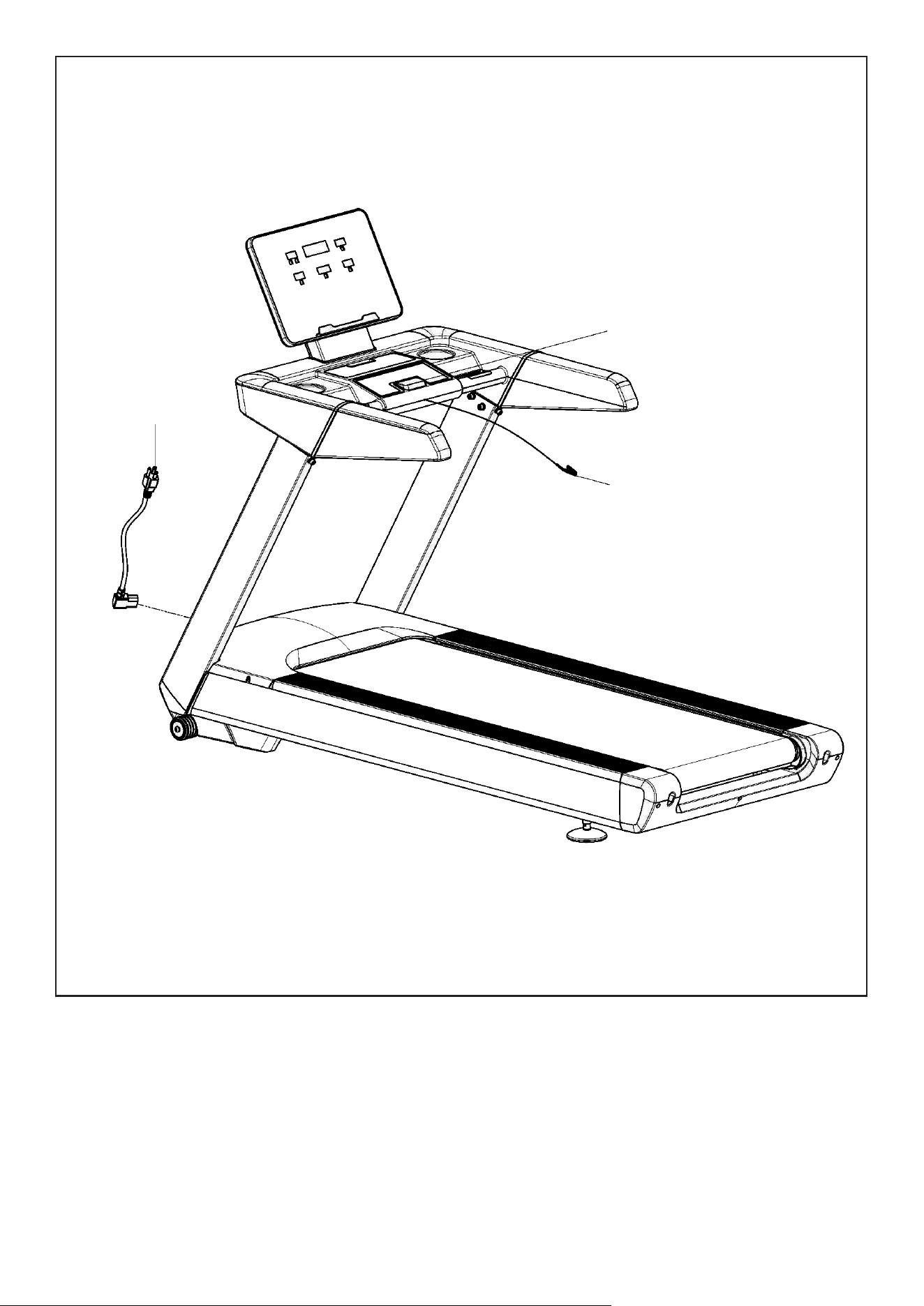
Connect the power cord to the back of the machine and plug to the wall socket. We don’t recommend
plugging on a Power board with other equipment as this is a high-powered equipment.
Turn on the power and you can begin workout. When not in use, you can turn off the power from the back
switch or the wall switch.
STEP 8
E22
C17
E14
ASSEMBLY INSTRUCTIONS |
16
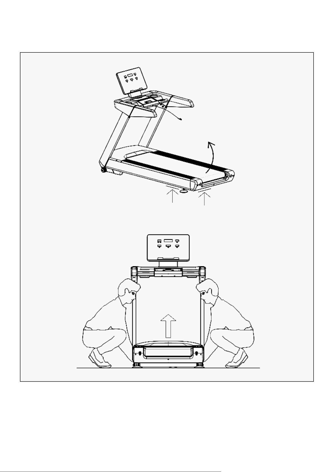
V. HOW TO MOVE THE TREADMILL
Transportation wheels are at the front of the machine and will need to be lifted from the back of the
treadmill and tilted onto the wheels.
The machine is heavy and may require 2 persons. Ensure to seek help if needed.
F
F
| HOW TO MOVE THE TREADMILL
17
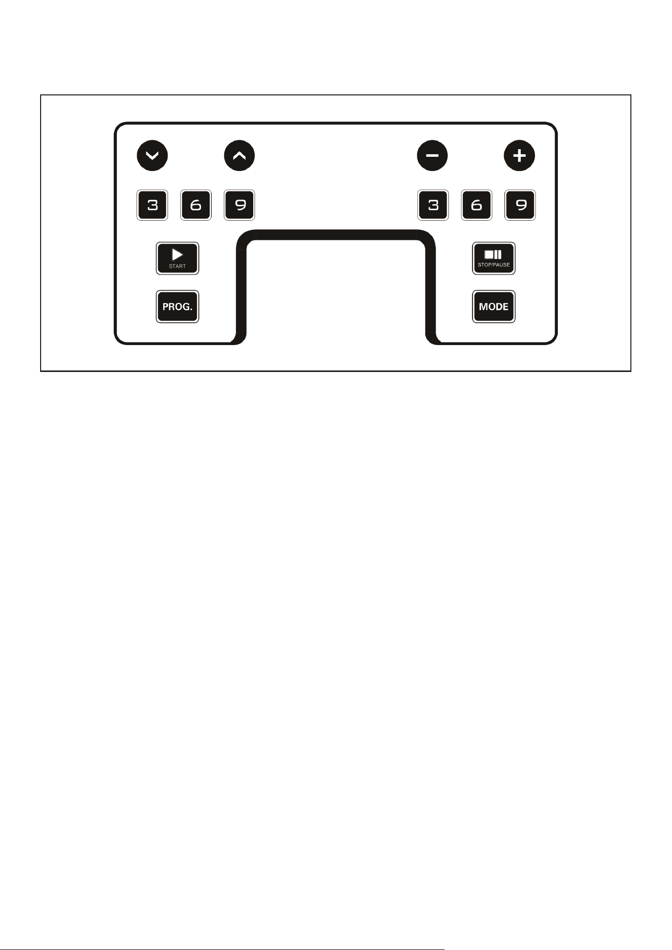
VI. OPERATION GUIDE
1. INCLINE -: Press this button to reduce the incline.
2. INCLINE +: Shows speed and program.
3. INSTANT INCLINE: Press 3, 6, 9 for quick incline adjustment.
4. START: Press this button to start the machine.
5. PROG: Press this button to choose between 24 programs, 3 user programs and body fat.
6. SPEED -: Press this button to reduce the speed.
7. SPEED +: Press this button to increase the speed.
8. INSTANT SPEED: Press 3, 6, 9 for quick speed adjustment.
9. STOP/PAUSE: Press 3, 6, 9 for quick speed adjustment.
10. MODE: Selection button. Press this button to choose between time, distance, calories workout
targets.
BUTTON FUNCTIONS:
OPERATION GUIDE |

18
1. MP3 INPUT: Insert MP3 cable to display the music from device.
2. USB INPUT: Charging your device.
MEDIA HUB:
1. INCLINE: Displays current incline. Press INCLINE+/- to adjust the incline of the machine.
2. SPEED: Displays current speed. Press SPEED+/- to adjust the speed of the machine.
3. CALORIES: Display the calories during workout.
4. TIME: Display the time duration of workout.
5. DISTANCE: Display the distance of the workout.
6. PULSE: Display user’s heart rate. This date is just for reference and cannot be regarded as medical
use. Both hands must hold the pulse sensors for about 5 seconds and the console will show users
pulse value.
7. MODE: Press Mode button to view TIME, DISTANCE, CALORIES, 24 programs, 3 User programs and body
fat setting.
7.1 Setting TIME, DISTANCE, CALORIES: From standby mode, press Mode button, the corresponding
light of TIME, DISTANCE, CALORIES will come on, select between TIME, DISTANCE, CALORIES.
- Press SPEED+/- or INCLINE+/- to set the workout target value.
- Press the START button, treadmill will run after 3 seconds.
- Press SPEED+/- to adjust the speed.
- Press INCLINE+/- to adjust the incline.
8. 24 Built-in Programs: From standby mode, press PROG button, console will show 24 programs, select
between 24 programs.
- Press SPEED+/- or INCLINE+/- to set the workout target value.
- Each program can be divided into 10 sections. Machine will beep 3 times when starting a new
section.
- You can still press SPEED+/- or INCLINE+/- to change the speed and incline during each section.
However, as it moves to the next section it will resume its pre-set Speed/Incline for that program.
- Once the program is completed it will beep 3 times.
8.1 User Programs: From standby mode, press PROG button, console will show 3 User programs, select
between 3 User programs.
- Press SPEED+/- or INCLINE+/- to set the workout target value.
- Each program can be divided into 10 sections. The machine will beep 3 times when starting a new
section. Use Mode to navigate to the sections to make changes on Speed and Incline.
COMPUTER FUNCTIONS:
| OPERATION GUIDE

19
- You can still press SPEED+/- or INCLINE+/- to change the speed and incline during each program.
- Once the program is completed it will beep 3 times.
- Press the START button, treadmill will run after 3 seconds.
- Press SPEED+/- to adjust the speed.
- Press INCLINE+/- to adjust the incline.
8.2 Body Fat Test: From standby mode, press PROG button until you get to FAT.
- Press Mode button to enter information.
Set value with SPEED+/- from F-1 to F-4 (F-1 GENDER, F-2 AGE, F-3 HEIGHT, F-4 WEIGHT)
- Press Mode button to enter F-5 (F—5 BODY FAT TEST), hold hands on the hand pulse sensor, the
console will display your body fat value after 3 seconds.
- The body fat value is intended as a guide only, and is not medical data.
Hold on the pulse sensor for about 5 seconds, the screen will show user’s pulse value. This data is just
for reference and cannot be regarded as medical data.
HANDPULSE FUNCTION:
This machine has lubrication reminder function. After every total running distance of 300km, the
treadmill screen will remind with lubrication. Please read the user’s manual first.
LUBRICATION REMINDER FUNCTION:
To reduce energy consumption, this treadmill will enter sleeping mode if it is without any operation for
10 minutes. The screen will give reminders before entering sleep mode. Once the machine enters sleep
mode, please take off safety key and insert again to awaken the system.
ENERGY SAVING FUNCTION:
F-1 Gender 01 Male 02 Female
F-2 Age 10-99
F-3 Height 100-200cm
F-4 Weight 20-150kg
F-5 FAT ≤19 Under Weight
FAT = (20---25) Normal Weight
FAT = (26---29) Overweight
FAT ≥30 Obesity
Switch off the power: You can switch off the power to stop the treadmill, this will not cause a problem to
the machine.
POWER ON (l) AND POWER OFF (O)
OPERATION GUIDE |
20
VII. EXERCISE GUIDE
PLEASE NOTE:
Before beginning any exercise program, consult your physician. This is important especially for
individuals over the age of 45 or with pre-existing health problems.
The pulse sensors are not medical devices. Various factors, including the user’s movement, may
affect the accuracy of heart rate readings. The pulse sensors are intended only as an exercise aid in
determining heart rate trends in general.
Exercising is a great way to control your weight, improve your fitness and reduce the effect of aging and
stress. The key to a healthy lifestyle is to make exercise a regular and enjoyable part of your everyday
life.
The condition of your heart and lungs and how efficient they are in delivering oxygen via your blood to
your muscles is an important factor to your fitness. Your muscles use this oxygen to provide enough
energy for daily activity. This is called aerobic activity. When you are fit, your heart will not have to work
so hard. It will pump a lot fewer times per minute, reducing the wear and tear of your heart.
So as you can see, the fitter you are, the healthier and greater you will feel.
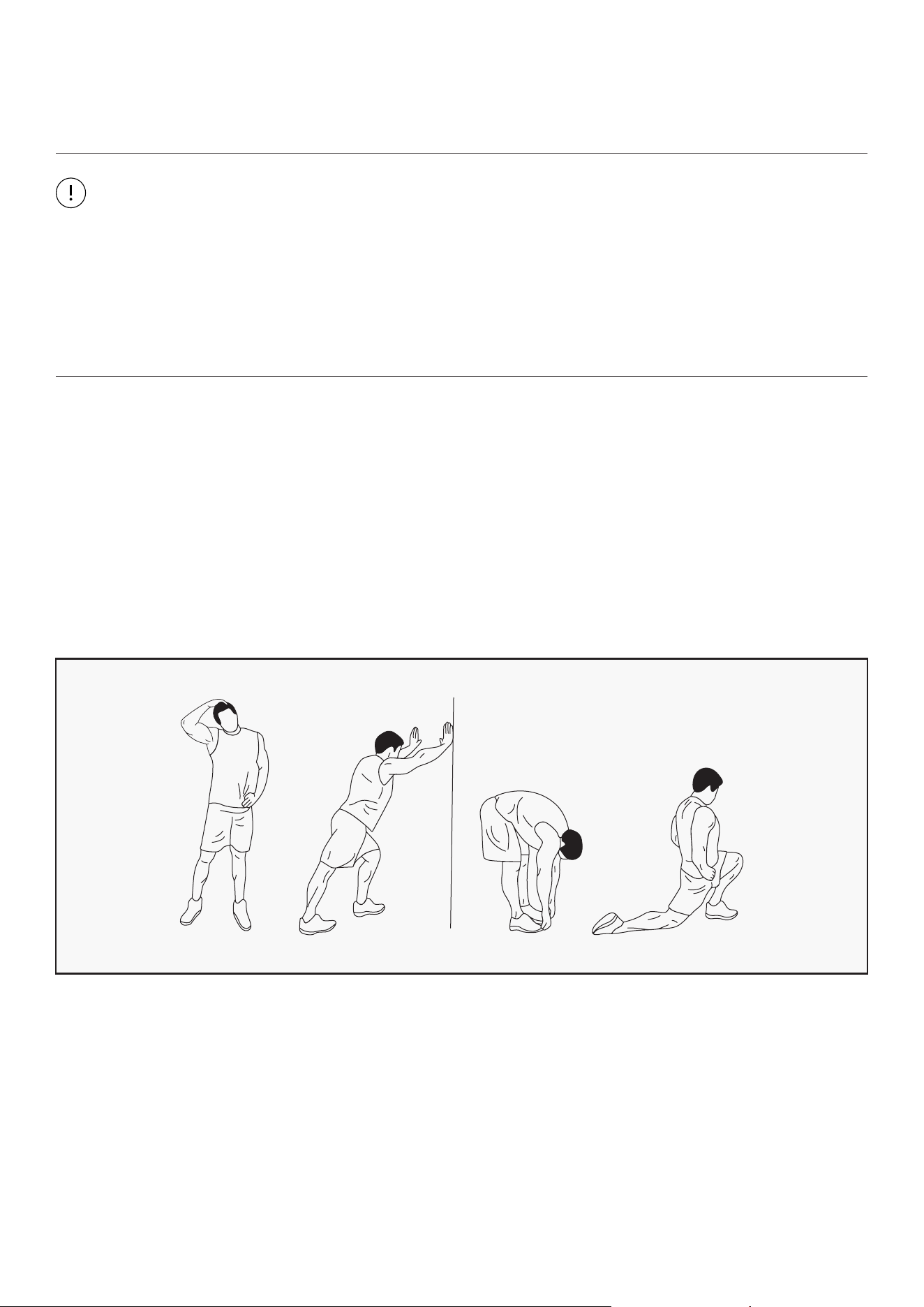
WARM UP
Start each workout with 5 to 10 minutes of stretching and some light exercises. A proper warm-up
increases your body temperature, heart rate and circulation in preparation for exercise. Ease into your
exercise.
After warming up, increase the intensity to your desired exercise program. Be sure to maintain your
intensity for maximum performance. Breathe regularly and deeply as you exercise.
| EXERCISE GUIDE
21
COOL DOWN
Finish each workout with a light jog or walk for at least 1 minute. Then complete 5 to 10 minutes of
stretching to cool down. This will increase the flexibility of your muscles and will help prevent post-
exercise problems.
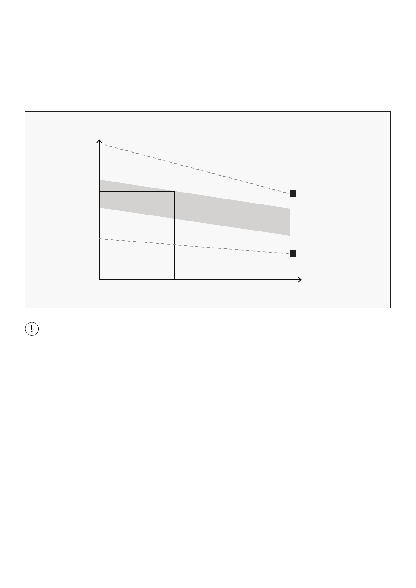
WORKOUT GUIDELINES
This is how your pulse should behave during general fitness exercise. Remember to warm up and
cool down for a few minutes.
TARGET ZONE
MAXIMUM
85%
70%
COOL DOWN
AGE
HEART RATE
200
180
160
140
120
100
80
20 25 30 35 40 45 50 55 60 65 70 75
The most important factor here is the amount of effort you put in. The harder and longer you work, the
more calories you will burn.
EXERCISE GUIDE |
22
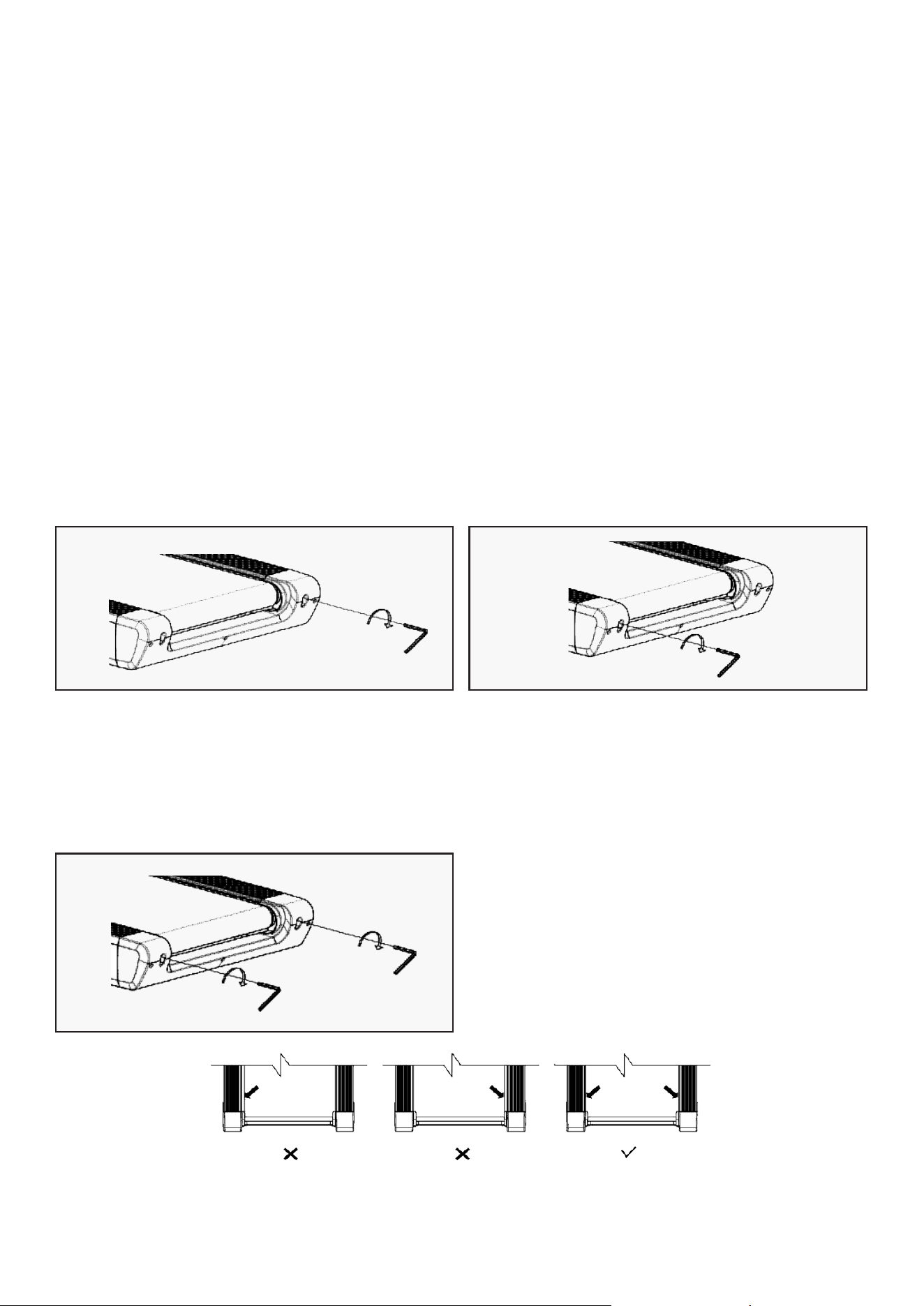
Place the treadmill on level ground and set it at 6-8kph to check if the Running Belt drifts.
CENTERING THE RUNNING BELT
VIII. MAINTENANCE INSTRUCTIONS
General cleaning will help prolong the life and performance of your treadmill. Keep the unit clean and
maintain it by dusting the components on a regular basis. Clean both sides of the running belt to
prevent dust from accumulating underneath the belt. Keep your running shoes clean so that dirt from
your shoes does not wear out the running board and belt. Clean the surface of the running belt with a
clean damp cloth.
• To better maintain the treadmill and prolong its life it is suggested that the machine be powered off
for 10 minutes every 2 hours and fully powered off whenever not in use.
• A loose Running Belt will result in the runner sliding off when running, while too tight of a Running
Belt will result in decrease to the motors performance and create more friction between the roller and
running belts. The most suitable tightness for the belts is pulled out 50-75mm from the Running
Board.
If the Running Belt moves to the right, turn
the adjusting bolt on the right side 1/4 turn
clockwise, then turn the left adjustment bolt
1/4 turn counterclockwise. If the belt does not
move, repeat this step until it centers. Refer to
figure A.
A
If the Running Belt moves to the left, turn the
adjusting bolts on the left side 1/4 of a turn
clockwise, then turn the right adjustment bolt
1/4 turn counterclockwise. If the belt does not
move, repeat this step until it centers. Refer to
figure B.
B
Over time the Running Belt will loosen. To
tighten the belt, turn the Left & Right-side
adjustment bolts one full turn clockwise, check
the tension of the belt. Continue this process
until belt is at the correct tension. Make sure to
adjust both sides equally to ensure correct belt
alignment. Refer to figure C.
C
| MAINTENANCE INSTRUCTIONS
23
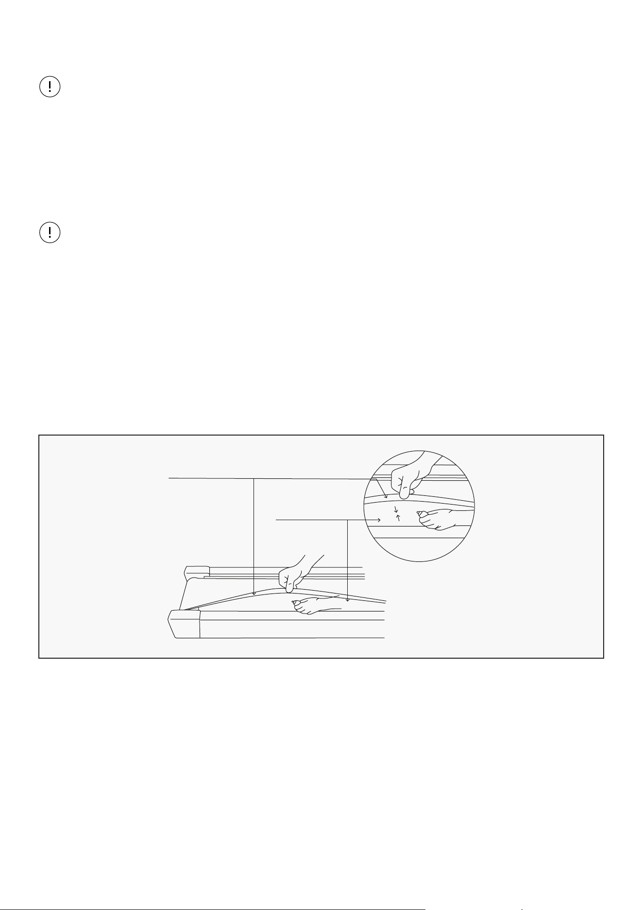
LUBRICATING THE TREADMILL
IMPORTANT NOTE:
You will need to lubricate your treadmill before the first use.
RUNNING BELTS & TREADMILL LUBRICANT:
Lubricating the running board and running belt is essential as the friction between the two affects the
life span and function of the treadmill, therefore it is suggested that the running board and belt be
inspected regularly.
WARNING:
Always unplug the treadmill from the electrical outlet before cleaning, lubricating, or repairing the
unit.
HOW TO LUBRICATE:
1. Raise the belt up on one side and apply lubricant to the running deck. Use a rag to thoroughly wipe
the lubricant over the running deck. Repeat this process for the other side.
2. The moving parts should turn freely and quietly. Abnormality of moving parts will affect the safety of
the equipment. Inspect and tighten bolts regularly.
3. To better maintain the treadmill and prolong its lifespan, it is suggested that maintenance be done
on a regular basis.
Running
Belt
Board
The following timetable is recommended:
• Light user (less than 3 hours/week) - every six months
• Medium user (3-5 hours/week) - every three months
• Heavy user (more than 5 hours/week) - every two months
MAINTENANCE INSTRUCTIONS |
24
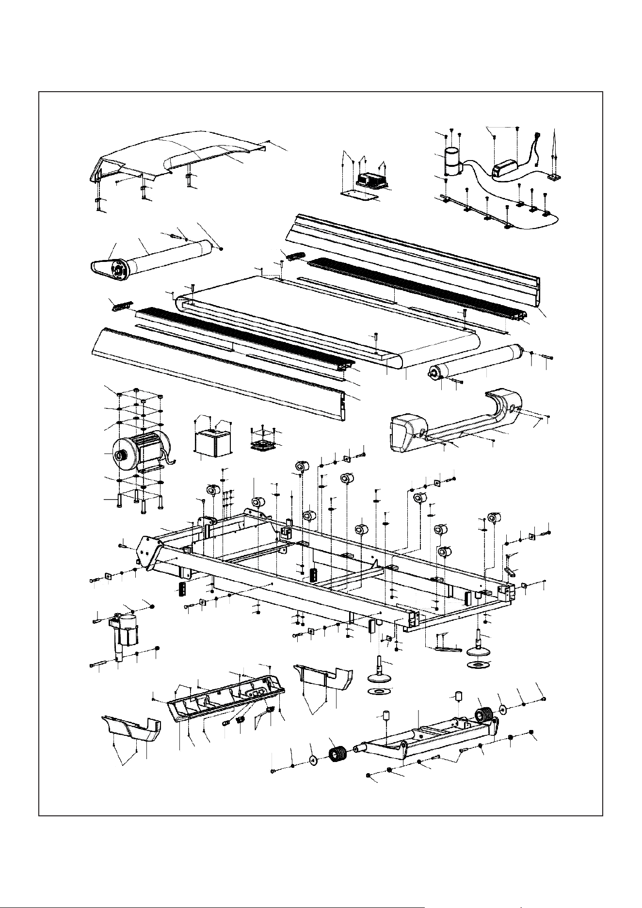
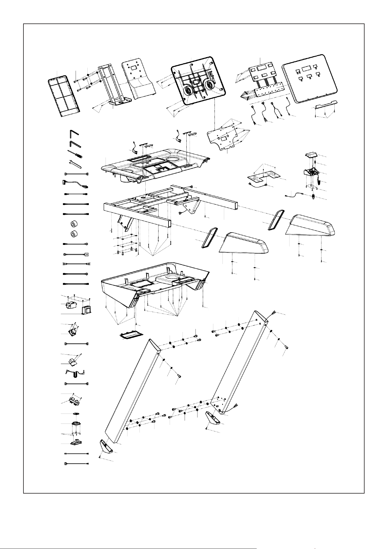
IX. EXPLODED DIAGRAM
| EXPLODED DIAGRAM
D16
B12
D24
B12
D24
B12
D24
C01
D16
C33
B01
D14
D28
D02
D25
D20
D20
E31
A08
F04
F01
F03
F02
F04
F05
C05
D38
D10
D38
D10
C06
D10
D10
C25
C07
C09
C07
C25
C08
E17
C32
D28
D13
B02
D28
D13
D37
D25
D37
D25
C10
D37
D01
D32
D33
E15
D33
D07
D20
D20
D19
E30
C27
D15
E18
C27
D25
C24
D18
D30
D29
D25
C24
D25
C28
D02
D34
B13
D09
D25
D25
C24
C24
C28
D25
C24
D25
C24
D02
D34
B13
D09
C28
D25
C24
C28
C27
C27
D25
C24
D02
D34
B13
D09
D36
A09
B07
D25
D28
D02
B03
C36
D36
A09
C29
D02
D28
D02
D28
D02
D28
D25
B07
B03
C36
C31
C31
A02
D05
D32
B06
C26
C26
B06
D32
D05
D01
C30
D33
D04
D33
C30
D01
C04
D25
D25
E21
D26
E20
E19
D25
D25
C02
C03
D25
D16
D16
D24
D24
D24
D16
D03
E16
D27
D01
D04
D27
D01
D09
B13
D34
D02
D08
C29
D28
D02
D09
B13
D34
D02
D28
D02
D28
D02
D09
B13
D34
D02
D28
D02
C29
C29
D28
D02
A01
D25
D15
C28
25EXPLODED DIAGRAM |
B08
B09
B10
B11
E08
E22
E23
E24
E25
E26
E27
E28
E29
E32
G04
G03
G05
G02
G01
J02
J01
K02
K03
K01
L03
L02
L04
L01
M05
M04
M06
M02
M03
M01
C21
D11
D34
C20
D22
A06
D24
C23
D24
E10
E01
D23
D23
C22
C37
D39
E03
E05
E09
E12
D24
D24
A07
E10
C13
B04
E06
D21
D34
D31
D12
D24
D21
C34
D24
A03
C15
D26
E04
E02
E13
C17
B05
C18
E14
D24
E11
C35
C16
D35
D17
D35
D17
D35
D17
D35
D17
C14
D25
D24
D25
D24
C19
D33
D32
D06
D32
D06
D33
E07
D33
D32
D06
D33
D32
D06
A05
C12
D16
D16
C11
A04
D33
D32
D06
D06
D32
D33

26
X. PARTS LIST
Key No. Description Qty.
A01 Main Frame 1
A02 Incline Bracket 1
A03
Console Base
Bracket
1
A04 Left Upright Tube 1
A05 Right Upright Tube 1
A06
Panel Connecting
Bracket
1
A07 Screen Holder 1
A08
Power Box Fixing
Plate
1
A09
Back-end Cover
Support Tube
2
B01 Front Roller 1
B02 Back Roller 1
B03 Versatile Foot Pad 2
B04 Pulse Steel Plate 4
B05 Spring 1
B06 Wheel Sleeve 2
B07
Side Rail Pressing
Plate
2
B08 6# Allen Wrench 6mm 1
B09 8# Allen Wrench 8mm 1
B10 Cross Screwdriver 1
B11 Open Wrench 1
B12
Motor Cover
Thread Board
3
B13
Side Rail Pressing
Plate
6
B15
iPad Holder
1
C01 Motor Top Cover 1
C02
Motor Bottom
Cover
1
C03
Motor Left Side
Cover
1
Key No. Description Qty.
C04
Motor Right Side
Cover
1
C05
Left Side Rail
Decoration
1
C06
Right Side Rail
Decoration
1
C07 Top Side Rail 2
C08 Left Side Rail 1
C09 Right Side Rail 1
C10 Back-end Cover 1
C11
Left Upright Tube
Cover
1
C12
Right Upright Tube
Cover
1
C13 Console Top Cover 1
C14
Console Bottom
Cover
1
C15 Left Handlebar 1
C16 Right Handlebar 1
C17 Emergency Button 1
C18 Button Holder 1
C19
Console Screw
Cover
1
C20
Console Support
Top Cover
1
C21
Console Support
Bottom Cover
1
C22 Panel Top Cover 1
C23
Panel Bottom
Cover
1
C24
Plastic Side Rail
Gasket
8
C25 Eva Pad 4
C26 Wheel 2
C27 Cushion 4
| PARTS LIST

27
Key No. Description Qty.
C28 Cushion 6
C29 Square Tube Plug 4
C30 Plastic Gasket 2
C31
Cylindrical
Cushion
2
C32 Running Belt 1
C33 Motor Belt 1
C34
Left Handlebar
Decorative Ring
1
C35
Right Handlebar
Decorative Ring
1
C36 Rubber Pad 2
C37 Holder 1
D01 Nut M10 8
D02 Nut M8 17
D03 Bolt M10*105 1
D04 Bolt M10*45 3
D05 Bolt M10*20 2
D06 Bolt M10*20 12
D07 Bolt M10*45 4
D08 Bolt M8*40 1
D09 Bolt M8*55 6
D10 Bolt M8*35 4
D11 Bolt M8*40 4
D12 Bolt M8*15 4
D13 Bolt M8*65 2
D14 Bolt M8*60 1
D15 Bolt M6*10 2
D16 Bolt M5*12 7
D17 Screw ST4.2*19 4
D18 Bolt M5*10 3
D19 Bolt M4*30 4
D20 Bolt M4*12 8
D21 Screw ST4.2*30 6
Key No. Description Qty.
D22 Screw ST4.2*25 2
D23 Screw ST2.9*8 18
D24 Screw ST4.2*12 41
D25 Screw ST4.2*12 25
D26 Screw ST2.9*8 5
D27 Lock Washer 10 2
D28 Lock Washer 8 13
D29 Lock Washer 5 3
D30 Spring Washer 5 3
D31 Spring Washer 8 4
D32 Spring Washer 10 18
D33 Flat Washer 10 22
D34 Flat Washer 8 14
D35 Big Washer ɸ5*ɸ15*1 4
D36 Screw ST4.2*20 4
D37 Screw ST4.2*12 3
D38 Screw ST4.2*12 2
D39 Screw ST2.9*12 3
E01 Console 1
E02
Touch Button
Board
1
E03
Touch Button Top
Signal Wire
1
E04
Touch Button
Bottom Signal
Wire
1
E05
Console Top Signal
Wire
1
E06
Console Middle
Signal Wire 1
1
E07
Console Middle
Signal Wire 2
1
E08
Console Bottom
Signal Wire
1
E09
Hand Pulse Top
Signal Wire
1
PARTS LIST |

28
Key No. Description Qty.
E10
Hand Pulse Bottom
Signal Wire
2
E11 Microswitch 1
E12
Switch Top Signal
Wire
1
E13
Switch Bottom
Signal Wire
1
E14 Safety Key 1
E15 AC Motor 1
E16 Incline Motor 1
E17 Running Board 1
E18 Inverter 1
E19 Overload Protecter 1
E20 Switch On-Off 1
E21 Power Socket 1
Key No. Description Qty.
E22 Power Wire 1
E23 AC Signal Wire 200 Brown 1
E24 AC Signal Wire 350 Brown 2
E25 AC Signal Wire 350 Blue 2
E26 Magnetic Ring 1
E27 Magnetic Core 3
E28 Ground Wire 350 2
E29
Running Board
Ground Wire
350 2
E30 Fan and Fan Wire 1
E31 Inverter Power Box 1
E32 Power Box Wire 1
OPTIONAL PARTS LIST
Key No. Description Qty.
F01 Oiling System 1
F02
Glass Tube Fixing
Knob
7
F03 Screw ST4.2*12 7
F04 Bolt M4*12 5
F05 Screw
ST2.9*8
2
G01 Filter 1
G02 Inductor 1
G03 AC Signal Wire 1
G04 Ground Wire 1
G05 Screw ST4.2*12 4
H01
Aluminum Alloy
Non-slip Pad
2
H02 Rubber Washer 24
H03 Screw ST4.2*12 24
J01 Specker 2
J02 Screw ST2.9*8 8
K01 USB Module 1
Key No. Description Qty.
K02
USB Connecting
Wire
1
K03 Screw ST2.9*8 2
L01 MP3 Module 1
L02 MP3 Data Wire 1
L03
MP3 Connecting
Wire
1
L04 Screw ST2.9*8 2
M01
Wireless Charging
Pinboard Wire
1
M02
Wireless Charging
Pinboard
1
M03
Wireless Charging
Board Wire
1
M04
Wireless Charging
Board
1
M05
Wireless Charging
Base
1
M06 Screw ST2.9*8 5
| PARTS LIST

29
TROUBLESHOOTING
Issue
Computer not turning on after
plugging to power
1. Please check if the overload protect jump, if yes, please
press it, let it continue to work.
2. Check if the wires of power switch, overload protect,
control board and the transformer are connected properly.
3. Remove the upright tube and check connection between
each wire, make sure each wire is plugged in properly. If
wires are damaged, please change the wire.
4. Check the transformer is working. If not, you will need to
change it.
TROUBLESHOOTING |
Solution
Display E01 Message Failure:
Probable Reason: The wires from computer and bottom
control board didn’t connect well, please check each wire. If
the wire is damaged, then change the wires. If this does not
fix the issue, then change to a new transformer.
Display E03 Solution Inverter Overvoltage: Check if the power supply
voltage is abnormal and if it is 50% higher than the normal
voltage. Please use the correct voltage to check again.
Display E04 or E12 Incline learning failed:
1. Check VR wire of incline motor is connected properly. If
not, reconnect VR to make it firm.
2. Check AC wire of motor is properly connected, and AC wire
of motor is inserted correctly on the control board.
3. Check connection line of motor for damage. If damaged,
then have it replaced. If cable is undamaged, then replace
the incline motor and press "learning" button of bottom
control board to relearn.
Display E06 Inverter MCU problem: The internal microcontroller of the
inverter is faulty. Please replace the inverter.
Display E07 Inverter is too hot:
1. The temperature of the inverter is too high. Please stop
and rest for a period of time and restart.
2. The treadmill is overloaded and the current is too high,
causing an increase in the internal temperature of the
inverter. Please increase the lubricating oil.

30| TROUBLESHOOTING
Issue
Display E08 The inverter can not receive signal from board.
1. The communication between the inverter and the display
is blocked. Check every connection between the display
and the inverter communication cable to ensure that
each wire core is fully inserted; Check if the connection
wire between the display and the inverter is damaged,
and replace the communication connection wire.
2. The communication circuit on the display is abnormal,
and the components are damaged. Replace the display.
3. The communication circuit on the inverter is abnormal,
and the components are damaged. Replace the inverter.
Solution
Display E09 or E10 Inverter internal signal problem.
1. The internal components of the inverter are damaged,
replace the inverter.
Display E11 Message failure:
Restart the treadmill. If issue persists, change the inverter.
Display E14 Inverter Problem:
Check if the wire and inverter wire are connected properly. If
not reconnect the motor wire to inverter wire.
If the above issue persists, change the inverter.
Display E15 or E16 Current Sensor U or W Problem:
1. Check if motor wire and inverter wire are connected
properly. If not, reconnect the motor wire to inverter
wire.
2. Check if the DC motor has any burning smell. If there
is, then the motor needs changing. If the issue persists,
change to a new inverter.

31
XI. WARRANTY
AUSTRALIAN CONSUMER LAW
Many of our products come with a guarantee or warranty from the manufacturer. In addition, they come
with guarantees that cannot be excluded under the Australian Consumer Law. You are entitled to a
replacement or refund for a major failure and compensation for any other reasonably foreseeable loss
or damage.
You are entitled to have the goods repaired or replaced if the goods fail to be of acceptable quality and
the failure does not amount to a major failure. Full details of your consumer rights may be found at
www.consumerlaw.gov.au.
Please visit our website to view our full warranty terms and conditions:
http://www.lifespanfitness.com.au/warranty-repairs
WARRANTY AND SUPPORT
Any claim against this warranty must be made through your original place of purchase.
Proof of purchase is required before a warranty claim may be processed.
If you have purchased this product from the Official Lifespan Fitness website, please visit
https://lifespanfitness.com.au/warranty-form
For support outside of warranty, if you wish to purchase replacement parts or request a repair or
service, please visit https://lifespanfitness.com.au/warranty-form and fill in our Repair/Service
Request Form or Parts Purchase Form.
Scan this QR code with your device to go to lifespanfitness.com.au/warranty-form
WARRANTY |

WWW.LIFESPANFITNESS.COM.AU