INSTALLATION GUIDE
US CA
RECIRCULATION KIT
KRECIRCDDFT

2
COMPONENTS REQUIRED
TOOLS
Not supplied
F Crosshead screwdriver
F Silicone - optional
PARTS
Supplied and required
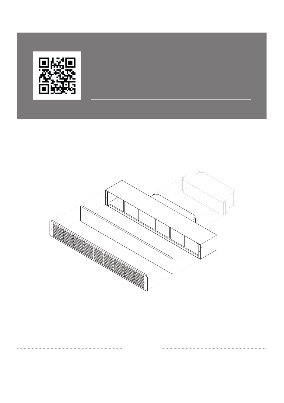
F 1x Filter Box
F 1x Carbon Filter
F 1x Stainless Steel Grille
F 4x Crosshead wood screws
F 2x Crosshead machine screws
Not supplied
F Metal Ducting*
F AD325X12X10 **
Adapter 3.25" x 12” to 3.25" x 10”
F Drive Cleats
F S Cleats
F Aluminium Tape
COMPATIBLE PRODUCTS
F CD5DB1
5" Series 11 Modular Auxiliary
Downdraft
F CID364DTB4
36" Series 9 4 Zone Induction Cooktop
with Integrated Ventilation
* Ducting must be purchased separately.
KRECIRCDDFT Recirculation Kit outlet is designed for 3.25" x 12" metal ducting.
CD5DB1 Modular Auxiliary Downdraft external blower outlet is designed for 3.25" x 12"
metal ducting.
CID364DTB4 36" Induction Cooktop with Integrated Ventilation is designed for 3.25" x 10”
** Available to purchase separately via fisherpaykel.com (compatible with CID364DTB4).
3
ACCESSING YOUR PRODUCT SPECIFICATIONS
For full product, cabinetry and service specifications, refer
to the Planning Guide. To access the Planning Guide, scan
the QR code or visit fisherpaykel.com/specify. Search by
appliance type, product name or model code.
IMPORTANT
Installation work must be done by qualified person(s) in accordance with all applicable
codes and standards.
4
PRIOR TO INSTALLATION
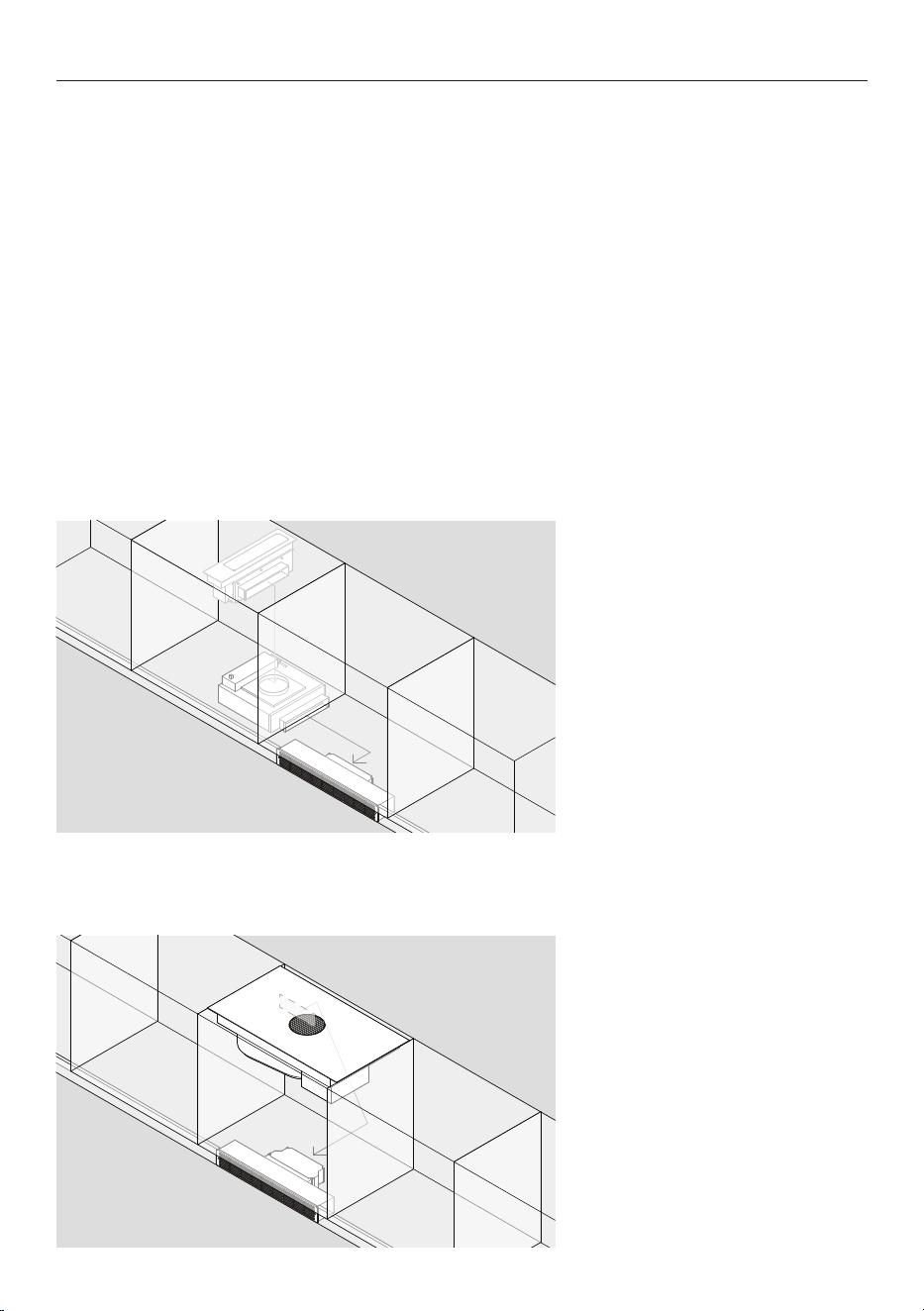
Plan ducting layout
Design duct route and plan sequence of installation. This will be specific to cabinetry design
and appliance placement.
Ensure cabinetry and servicing specifications have been met and clearances have been
considered.
Refer to individual cooktop Planning Guides for details.
CD5DB1 models only:
Example duct route.
CID364DTB4 models only:
Example duct route.
5
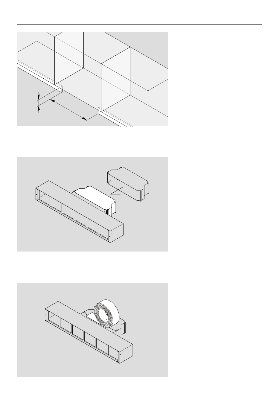
PREPARATION
1. Create a 27 3/4” x 3 7/8” (705
x 99mm) cutout in toe kick for
recirculation kit.
2. If required, connect adapter
to filter box.
3. If required, pre-assemble
metal ducting to filter box.
4. Secure ducting with drive
and S cleats as required and
seal all joins with aluminium
tape.
6
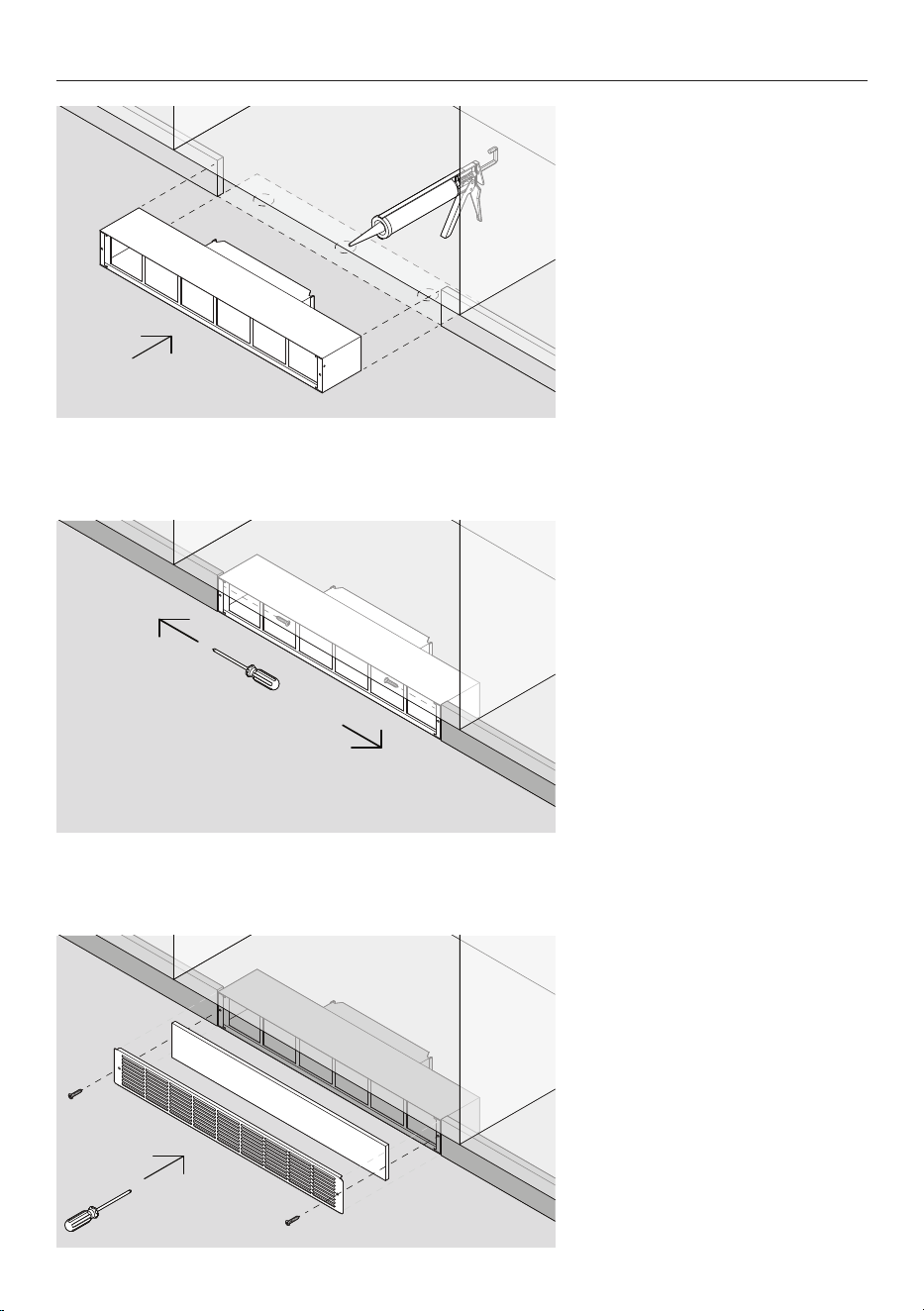
3. Align filter and grille. Ensure
the filter is placed evenly over
cutout so air cannot bypass it.
Secure grille to filter box with
machine screws supplied.
INSTALLATION
2. If required, secure filter box
to cabinetry with wood screws
supplied.
If not secured previously, attach
and seal ducting to product
outlet.
1. Position filter box in cutout.
If required, use adhesive to
secure.

7
Complete and keep for safe reference:
Model
Serial no.
Purchase date
Purchaser
Dealer address
Installer’s name
Installer’s signature
Installation company
Installation date
INSTALLER CHECKLIST
TO BE COMPLETED BY THE INSTALLER
GENERAL
F Only metal ducting has been used.
F Recirculation Kit has been securely fastened.
F Ducting has been secured.
F All duct joints have been sealed with aluminium tape.

432900A 03.25
FISHERPAYKEL.COM
© Fisher & Paykel Appliances 2025. All rights reserved.
The models shown in this guide may not be available in all markets
and are subject to change at any time.
The product specifications in this guide apply to the specific products and
models described at the date of issue. Under our policy of continuous product
improvement, these specifications may change at any time.
For current details about model and specification availability in your country,
please go to our website or contact your local Fisher&Paykel dealer.