
Technical Support and E-Warranty Certificate www.vevor.com/support
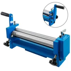
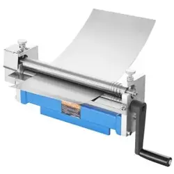
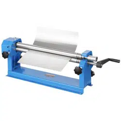
VENEER REELING MACHINE
OPERATION MANUAL
MODEL:W01-0.8X610
We continue to be committed to provide you tools with competitive price.
"Save Half", "Half Price" or any other similar expressions used by us only represents an
estimate of savings you might benefit from buying certain tools with us compared to the major
top brands and does not necessarily mean to cover all categories of tools offered by us. You
are kindly reminded to verify carefully when you are placing an order with us if you are
actually saving half in comparison with the top major brands.


- 1 -
MODEL:W01-0.8X610
Have product questions? Need technical support? Please feel free to
contact us:
Technical Support and E-Warranty Certificate
www.vevor.com/support
NEED HELP? CONTACT US!
This is the original instruction, please read all manual instructions
carefully before operating. VEVOR reserves a clear interpretation of our
user manual. The appearance of the product shall be subject to the
product you received. Please forgive us that we won't inform you again if
there are any technology or software updates on our product.
VENEER REELING
MACHINE

- 2 -
Warning-To reduce the risk of injury, user must read
instructions manual carefully.
SPECIFICATIONS
Model......................................................................................W01-0.8X610
Minimum Roll Diameter......................................................................60mm
Maximum Roll Length.......................................................................610mm
Max. Thickness.....................................................................................1mm
Standard accessories
Planker................................................................................................1
Save This Manual
You will need the manual for the safety warnings and precautions,
assembly instructions, operating and maintenance procedures, parts list
and diagram. Keep your invoice with this manual. Write the invoice number
on the inside of the front cover. Keep the manual and invoice in a safe and
dry place for future reference.

- 3 -
READ THIS INSTRUCTIONS BEFORE USING THIS TOOL
1. KEEP WORK AREA CLEAN. Cluttered areas invite injuries.
2. CONSIDER WORK AREA CONNECTIONS. Don’t use tools in damp,
wet, or poorly lit locations. Don’t expose to rain. Keep work area well lit.
3. KEEP CHILDREN AWAY. All children should be kept away from work
area.
4. STOCK IDLE EQUIPMENT. When not in use, tools should be locked up
in a dry location to inhibit rust. If possible, store in an area out of reach of
children.
5. USE THE RIGHT TOOL. Don’t force a small tool or attachment to do the
work of a larger industrial tool. Don’t use a larger industrial tool. Don’t use
a tool for a purpose for which it was not intended.
6. DRESS PROPERLY. Don’t wear loose clothing or jewelry. Non-skid
footwear is recommended when working to prevent slipping. Wear
protective hair covering to contain long hair.
7. USE EYE PROTECTION. Wear approved impact goggles at all times
when using this tool.
8. SECURE WORK. Use clamps or a vise to hold the work if possible. It’s
safer than using your bands and it frees both hands to operate the tool.
9. DON’T OVERREACH. Keep handles dry. Clean, and free from oil and
grease. Follow instructions for lubricating and changing accessories.
10. MAINTAIN TOOL WITH CARE. Keep handles dry, clean, and free from
oil and grease. Follow instructions for lubricating and changing
accessories.
11. CHECK DAMAGE PARTS. Before using any tool, any parts that
appear damaged should be carefully checked to determine that it will
operate properly and perform its intended function. Check for alignment of
moving parts, binding of moving parts, breakage of parts, mounting, and
other conditions that may affect its operation. Any part that is damaged
should be properly repaired or replaced by an authorized service center
unless otherwise indicated elsewhere in the instruction manual.
12. REPLACEMENT PARTS AND ACCESSORIES. When serving, use
only identical replacement parts. Only use accessories intended for use

- 4 -
with this tool.
13. DON’T OPERAYE TOOL IF UNDER THE INFLUENCE OF ALCOHOL
OR DRUGS. Read warning labels on prescription to determine if your
judgment or reflexes are impaired while taking drugs. If there is any
doubt, don’t operate machine.
14. NEVER STAND ON TOOL. If tool is tipped over, serious injury or
product damage could result.
UNPACKING
The Slip Roll machine should come assembled when unpacked. Look for
any loose parts in the packing material before discarding. If any are found,
try and find the part on the machine is missing or broken, please call the
Distributor as soon as possible.

- 5 -
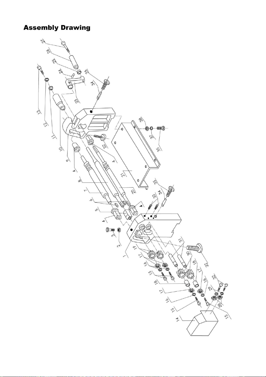
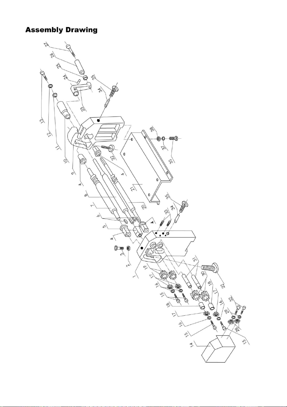
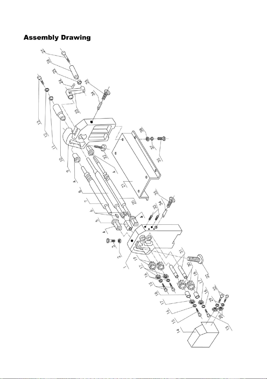
ASSEMBLY AND ADJUSTMENT
1. Mount the Slip Roll machine to a bench by bolting the base of the
machine (#21) to the bench. Refer to the Parts Diagram.
2. Adjust distance between Shaft 1 (#8) and Shaft 2 (#20) if necessary.
a. The distance between Shaft 2 (#20) and Shaft 1 (#8) can be adjusted
by turning the Adjusting Bolts (#35)
b. To decrease the distance between the two shafts, turn the Adjusting
Bolt (#35) clockwise.
c. To increase the distance, turn the Adjusting Bolt (#35)
counterclockwise.
3. Adjust distance between Shaft 1 (#8) and Shaft 3 (#7) if necessary
a. The distance between Shaft 3 (#7) and Shaft 1 (#8) can be adjusted
by turning the Adjusting Bolts (#22).
b. To decrease the distance between the two shafts, turn the Adjusting
Bolts (#22) clockwise.
c. To increase the distance, turn the Adjusting Bolts (#22)
counterclockwise.
4. Removal of Shaft 1 (#8) if necessary. The left end of Shaft 1 is mounted
on a Square Bushing (#5), and the right end of Shaft 1 is mounted
through the Right Stand (#9) into the Sleeve (#10).
a. To remove Shaft 1, remove the Sleeve (#10) off the right end of Shaft
1.
b. Next, at the top of the Left Stand, loosen Hex Bolt (#3).
c. Pull the right end of the Shaft 1 outward.
5. Remounting Shaft 1
a. Reinsert the right end of Shaft 1 into the hole in the Right Stand.
b. Tighten Hex Bolt (#3) on the top of the Left Stand.
c. Push the Sleeve (#10) onto the end of Shaft 1

- 6 -
OPERATION
Before using, check the mounting and adjustment of this machine. Rotate
the Handle (#23) and check whether the four gears (#19, #30) have good,
firm contact with each other. Shafts 1, 2 and 3 should be clean and free of
metal debris. Refer to the Parts Diagram.
Forming Rolls
1. Insert the steel plate between Shaft 1 (#8) and Shaft 2 (#20).
2. Rotate the Handle (#23) to form the metal roll.
3. If the diameter of the metal roll is not correct, turn the Adjusting Bolts
(#22) clockwise to decrease the diameter, of counterclockwise to increase
the diameter of the roll.
4. To remove the finished roll, pull out Sleeve (#10) on the end of Shaft 1
(#8), nearest the Handle (#23), and swing Shaft 1 out of the Right Stand.
Then remove the steel roll from Shaft 1.
Forming Rings
The half-round slots on the right side of Shaft 2 (#20) and Shaft 3 (#7) can
beused to form rings of various dimensions.
1. Insert the steel in half-round slot of Shaft 2 (#20) or Shaft 3 (#7).
2. Rotate the Handle (#23) to form the metal ring.
WARNING: Keep the hands away from the shafts and metal plate during
operation. Do not attempt to form rolls from materials other than those
specified

- 7 -
PARTS LIST
Part #
Description
Qty
1
Left Stand
1
2
Nut M12
1
3
Hex Bolt M12x40
1
4
Support Bushing
4
5
Square Bushing
1
6
Flat Key 4x20
2
7
Shaft 3
1
8
Shaft 1
1
9
Right Stand
1
10
Sleeve
1
11
Washer
1
12
Spring Washer
1
13
Screw M8x16
1
14
Cover
1
15
Hex Bolt M8x16
4
16
Spring Washer
4
17
Washer
4
18
Bearing
2
19
Small Gear
2
20
Shaft 2
1
21
Base
1
22
Adjusting Bolt
2
23
Handle
1
24
Locking Screw M6x10
1
25
Hex Nut M10
1
26
Handle Bushing
1
27
Hex Bolt M10x10
1
28
Washer
2
29
Spring Washer
2
30
Large Gear
2
31
Small Shaft
2
32
Hex Bolt M6x10
2
33
Locking Screw M8x30
2
34
Pin
2
35
Adjusting Bolt
2
36
Hex Bolt M12x20
4
37
Spring Washer
4
38
Flat Washer
4
- 8 -


Technique Certificat d'assistance et de garantie électronique
www.vevor.com/support
MACHINE À DÉVIDER LE PLACAGE
MANUEL D'UTILISATION
MODÈLE : W01-0.8X610
We continue to be committed to provide you tools with competitive price.
"Save Half", "Half Price" or any other similar expressions used by us only represents an
estimate of savings you might benefit from buying certain tools with us compared to the major
top brands and does not necessarily mean to cover all categories of tools offered by us. You
are kindly reminded to verify carefully when you are placing an order with us if you are
actually saving half in comparison with the top major brands.

- 1 -
MODÈLE : W01-0.8X610
Have product questions? Need technical support? Please feel free to
contact us:
Technical Support and E-Warranty Certificate
www.vevor.com/support
NEED HELP? CONTACT US!
This is the original instruction, please read all manual instructions
carefully before operating. VEVOR reserves a clear interpretation of our
user manual. The appearance of the product shall be subject to the
product you received. Please forgive us that we won't inform you again if
there are any technology or software updates on our product.
VENEER REELING
MACHINE

- 2 -
Avertissement - Pour réduire le risque de blessure,
l'utilisateur doit lire attentivement le manuel d'instructions.
SPECIFICATIONS
Modèle....................................................................................... ..
W01-0.8X610
Diamètre minimal du rouleau .................................................................. .....
60 mm
Longueur maximale du rouleau ................................................................. ..
610 mm
Épaisseur max ............................................................................... .......1
mm
Accessoires standards
Planeur ....... ......................................... ....... ......................................... 1
Sauvegarder ce manuel
Vous aurez besoin du manuel pour les avertissements et précautions de
sécurité, l'assemblage instructions, procédures d'utilisation et d'entretien,
liste des pièces et schéma. Conservez votre facture avec ce manuel.
Inscrivez le numéro de facture à l'intérieur la couverture avant. Conservez
le manuel et la facture dans un endroit sûr et sec pour référence future.

- 3 -
LISEZ CES INSTRUCTIONS AVANT D'UTILISER CET OUTIL
1. GARDEZ LA ZONE DE TRAVAIL PROPRE. Les zones encombrées
favorisent les blessures.
2. TENEZ COMPTE DES CONNEXIONS DE LA ZONE DE TRAVAIL.
N'utilisez pas d'outils dans des endroits humides,
endroits humides ou mal éclairés. Ne pas exposer à la pluie. Garder la
zone de travail bien éclairée.
3. ÉLOIGNEZ LES ENFANTS. Tous les enfants doivent être tenus à l'écart
du travail.
zone.
4. STOCKER LES ÉQUIPEMENTS AU RETARD. Lorsqu'ils ne sont pas
utilisés, les outils doivent être verrouillés
dans un endroit sec pour éviter la rouille. Si possible, rangez-le dans un
endroit hors de portée des
enfants.
5. UTILISEZ LE BON OUTIL. Ne forcez pas un petit outil ou un accessoire
pour effectuer la tâche.
travail d'un outil industriel plus grand. N'utilisez pas d'outil industriel plus
grand. N'utilisez pas
un outil destiné à un usage pour lequel il n’a pas été conçu.
6. HABILLEZ-VOUS CORRECTEMENT. Ne portez pas de vêtements
amples ni de bijoux. Antidérapant
Il est recommandé de porter des chaussures lorsque vous travaillez pour
éviter de glisser.
couverture protectrice des cheveux pour contenir les cheveux longs.
7. UTILISEZ DES PROTECTIONS POUR LES YEUX. Portez toujours des
lunettes de protection homologuées contre les chocs.
lors de l'utilisation de cet outil.
8. FIXEZ LE TRAVAIL. Utilisez des pinces ou un étau pour maintenir le

- 4 -
travail si possible.
plus sûr que d'utiliser vos bandes et cela libère les deux mains pour utiliser
l'outil.
9. NE PAS TROP ALLER. Garder les poignées sèches. Nettoyer et
exemptes d'huile et de graisse.
graisse. Suivez les instructions pour la lubrification et le changement des
accessoires.
10. ENTRETENEZ L'OUTIL AVEC SOIN. Gardez les poignées sèches,
propres et exemptes d'huile et de graisse. Suivez les instructions pour la
lubrification et le changement des accessoires.
11. VÉRIFIEZ LES PIÈCES ENDOMMAGÉES. Avant d'utiliser un outil,
vérifiez toutes les pièces qui semblent endommagées. endommagé doit
être soigneusement vérifié pour déterminer s'il fonctionnera correctement
et remplir sa fonction prévue. Vérifiez l'alignement de
pièces mobiles, blocage des pièces mobiles, rupture des pièces, montage
et
d'autres conditions qui peuvent affecter son fonctionnement. Toute pièce
endommagée
doit être correctement réparé ou remplacé par un centre de service agréé
sauf indication contraire ailleurs dans le manuel d'instructions.
12. PIÈCES DE RECHANGE ET ACCESSOIRES. Lors du service, utilisez
uniquement pièces de rechange identiques. Utilisez uniquement des
accessoires destinés à être utilisés avec cet outil.
13. N'UTILISEZ PAS L'OUTIL SI VOUS ÊTES SOUS L'INFLUENCE DE
L'ALCOOL
OU DES MÉDICAMENTS. Lisez les étiquettes d'avertissement sur les
ordonnances pour déterminer si votre
le jugement ou les réflexes sont altérés lors de la prise de médicaments.
S'il y a des
doute, n'utilisez pas la machine.
14. NE JAMAIS SE TENIR SUR L'OUTIL. Si l'outil bascule, des blessures
graves ou des dommages au produit peuvent survenir. des dommages
pourraient en résulter.

- 5 -
UNPACKING
La machine Slip Roll doit être livrée assemblée lors du déballage.
Recherchez
toutes les pièces détachées du matériel d'emballage avant de les jeter. Si
vous en trouvez,
essayez de trouver la pièce sur la machine manquante ou cassée, veuillez
appeler le
Distributeur dans les plus brefs délais.
ASSEMBLY AND ADJUSTMENT
1. Montez la machine Slip Roll sur un banc en boulonnant la base du
machine (#21) sur l'établi. Reportez-vous au schéma des pièces.

- 6 -
2. Ajustez la distance entre l'arbre 1 (#8) et l'arbre 2 (#20) si nécessaire.
a. La distance entre l'arbre 2 (#20) et l'arbre 1 (#8) peut être ajustée
en tournant les boulons de réglage (#35)
b. Pour diminuer la distance entre les deux arbres, tournez le bouton de
réglage
Boulon (#35) dans le sens des aiguilles d'une montre.
c. Pour augmenter la distance, tournez le boulon de réglage (#35) dans
le sens inverse des aiguilles d'une montre.
3. Ajustez la distance entre l'arbre 1 (#8) et l'arbre 3 (#7) si nécessaire
a. La distance entre l'arbre 3 (#7) et l'arbre 1 (#8) peut être ajustée
en tournant les boulons de réglage (#22).
b. Pour diminuer la distance entre les deux arbres, tournez le bouton de
réglage
Boulons (#22) dans le sens des aiguilles d'une montre.
c. Pour augmenter la distance, tournez les boulons de réglage (#22)
dans le sens inverse des aiguilles d'une montre.
4. Retrait de l'arbre 1 (#8) si nécessaire. L'extrémité gauche de l'arbre 1 est
montée
sur une bague carrée (#5), et l'extrémité droite de l'arbre 1 est montée
à travers le support droit (#9) dans le manchon (#10).
a. Pour retirer l'arbre 1, retirez le manchon (n° 10) de l'extrémité droite
de l'arbre
1.
b. Ensuite, en haut du support gauche, desserrez le boulon hexagonal
(n° 3).
c. Tirez l’extrémité droite de l’arbre 1 vers l’extérieur.
5. Remontage de l'arbre 1
a. Réinsérez l’extrémité droite de l’arbre 1 dans le trou du support droit.
b. Serrez le boulon hexagonal (n° 3) sur le dessus du support gauche.
c. Poussez le manchon (#10) sur l'extrémité de l'arbre 1

- 7 -
OPERATION
Avant d'utiliser cette machine, vérifiez le montage et le réglage.
la poignée (#23) et vérifiez si les quatre engrenages (#19, #30) sont bons,
contact ferme les uns avec les autres. Les arbres 1, 2 et 3 doivent être
propres et exempts
débris métalliques. Reportez-vous au schéma des pièces.
Rouleaux de formage
1. Insérez la plaque d’acier entre l’arbre 1 (#8) et l’arbre 2 (#20).
2. Faites tourner la poignée (#23) pour former le rouleau métallique.
3. Si le diamètre du rouleau métallique n'est pas correct, tournez les
boulons de réglage (#22) dans le sens des aiguilles d'une montre pour
diminuer le diamètre, ou dans le sens inverse des aiguilles d'une montre
pour l'augmenter. diamètre du rouleau.
4. Pour retirer le rouleau terminé, retirez le manchon (n° 10) à l'extrémité
de l'arbre 1
(#8), le plus proche de la poignée (#23), et faites pivoter l'arbre 1 hors du
support droit.
Retirez ensuite le rouleau en acier de l’arbre 1.
Former des anneaux
Les fentes demi-rondes situées sur le côté droit de l'arbre 2 (#20) et de
l'arbre 3 (#7) peuvent être utilisées pour former des anneaux de différentes
dimensions.
1. Insérez l'acier dans la fente demi-ronde de l'arbre 2 (#20) ou de l'arbre 3
(#7).
2. Faites tourner la poignée (#23) pour former l’anneau métallique.
AVERTISSEMENT : Gardez les mains éloignées des tiges et des pièces
métalliques plaque pendant le fonctionnement. N'essayez pas de former

- 8 -
des rouleaux à partir matériaux autres que ceux spécifiés
PARTS LIST
Partie #
Description
Quantité
1
Tribune de gauche
1
2
Écrou M12
1
3
Boulon à tête hexagonale M12x40
1
4
Bague de support
4
5
Douille carrée
1
6
Clé plate 4x20
2
7
Arbre 3
1
8
Arbre 1
1
9
Béquille droite
1
10
Manche
1
11
Rondelle
1
12
Rondelle élastique
1
13
Vis M8x16
1
14
Couverture
1
15
Boulon hexagonal M8x16
4
16
Rondelle élastique
4
17
Rondelle
4
18
Palier
2
19
Petit engin
2
20
Arbre 2
1
21
Base
1
22
Boulon de réglage
2
23
Poignée
1
24
Vis de blocage M6x10
1
25
Écrou hexagonal M10
1
26
Bague de poignée
1
27
Boulon à tête hexagonale M10x10
1
28
Rondelle
2
29
Rondelle élastique
2
30
Gros engrenage
2
31
Petit arbre
2
32
Boulon à tête hexagonale M6x10
2

- 9 -
33
Vis de blocage M8x30
2
34
Épingle
2
35
Boulon de réglage
2
36
Boulon à tête hexagonale M12x20
4
37
Rondelle élastique
4
38
Rondelle plate
4

- 10 -


Technisch Support und E-Garantie-Zertifikat www.vevor.com/support
FURNIERHASPELMASCHINE
BEDIENUNGSANLEITUNG
MODELL: W01-0.8X610
We continue to be committed to provide you tools with competitive price.
"Save Half", "Half Price" or any other similar expressions used by us only represents an
estimate of savings you might benefit from buying certain tools with us compared to the major
top brands and does not necessarily mean to cover all categories of tools offered by us. You
are kindly reminded to verify carefully when you are placing an order with us if you are
actually saving half in comparison with the top major brands.


- 1 -
MODELL: W01-0.8X610
Have product questions? Need technical support? Please feel free to
contact us:
Technical Support and E-Warranty Certificate
www.vevor.com/support
NEED HELP? CONTACT US!
This is the original instruction, please read all manual instructions
carefully before operating. VEVOR reserves a clear interpretation of our
user manual. The appearance of the product shall be subject to the
product you received. Please forgive us that we won't inform you again if
there are any technology or software updates on our product.
VENEER REELING
MACHINE

- 2 -
Warnung: Um das Verletzungsrisiko zu verringern, muss
der Benutzer die Bedienungsanleitung sorgfältig lesen.
SPECIFICATIONS
Modell................................................................................... ..
W01-0.8x610
Minimaler
Rollendurchmesser.............. .................................................... ..... 60 mm
Maximale Rollenlänge.................. ..................................................... .. 610
mm
Max.
Dicke................................... ..................................................... .......1mm
Standardzubehör
Planker ....... ......................................... ....... ......................................... 1
Bewahren Sie dieses Handbuch auf
Sie benötigen das Handbuch für die Sicherheitshinweise und
Vorsichtsmaßnahmen, Montage Anweisungen, Betriebs- und
Wartungsverfahren, Teileliste und Diagramm. Bewahren Sie Ihre
Rechnung zusammen mit diesem Handbuch auf. Schreiben Sie die
Rechnungsnummer auf die Innenseite der Frontabdeckung. Bewahren Sie
das Handbuch und die Rechnung an einem sicheren und trockenen Ort auf.
zukünftige Bezugnahme.

- 3 -
LESEN SIE DIESE ANLEITUNG, BEVOR SIE DIESES WERKZEUG
VERWENDEN
1. HALTEN SIE DEN ARBEITSBEREICH SAUBER. Unordnung führt zu
Verletzungen.
2. BEACHTEN SIE DIE ARBEITSBEREICHSANSCHLÜSSE. Benutzen
Sie keine Werkzeuge in feuchten,
nasse oder schlecht beleuchtete Orte. Nicht dem Regen aussetzen.
Sorgen Sie für eine gute Beleuchtung des Arbeitsbereichs.
3. HALTEN SIE KINDER FERN. Alle Kinder sollten von der Arbeit
ferngehalten werden
Bereich.
4. LAGERUNG VON NICHT VERWENDETEN GERÄTEN. Wenn
Werkzeuge nicht verwendet werden, sollten sie weggeschlossen werden.
an einem trockenen Ort, um Rost zu vermeiden. Lagern Sie es möglichst
außerhalb der Reichweite von
Kinder.
5. VERWENDEN SIE DAS RICHTIGE WERKZEUG. Zwingen Sie ein
kleines Werkzeug oder einen Aufsatz nicht dazu, die
Arbeit eines größeren Industriewerkzeugs. Verwenden Sie kein größeres
Industriewerkzeug. Verwenden Sie kein
ein Werkzeug für einen Zweck, für den es nicht bestimmt ist.
6. PASSENDE KLEIDUNG. Tragen Sie keine weite Kleidung oder
Schmuck. Rutschfeste
Bei der Arbeit wird Schuhwerk empfohlen, um ein Ausrutschen zu
verhindern. Tragen Sie
schützende Haarbedeckung zum Zusammenhalten von langem Haar.
7. AUGENSCHUTZ VERWENDEN. Tragen Sie immer eine zugelassene

- 4 -
Schutzbrille .
bei der Verwendung dieses Werkzeugs.
8. SICHERN SIE DAS WERK. Verwenden Sie wenn möglich Klemmen
oder einen Schraubstock, um das Werk zu fixieren.
sicherer als die Verwendung Ihrer Bänder und Sie haben beide Hände frei,
um das Werkzeug zu bedienen.
9. NICHT ZU ÜBERGREIFEN. Halten Sie die Griffe trocken. Sauber und
frei von Öl und
Fett. Befolgen Sie die Anweisungen zum Schmieren und Wechseln von
Zubehör.
10. WARTUNG DES WERKZEUGS SORGFÄLTIG. Halten Sie die Griffe
trocken, sauber und frei von Öl und Fett. Befolgen Sie die Anweisungen
zum Schmieren und Wechseln des Zubehörs.
11. ÜBERPRÜFEN SIE BESCHÄDIGTE TEILE. Bevor Sie ein Werkzeug
verwenden, überprüfen Sie alle Teile, die beschädigt ist, sollte sorgfältig
überprüft werden, um sicherzustellen, dass es funktioniert ordnungsgemäß
funktionieren und ihre vorgesehene Funktion erfüllen. Überprüfen Sie die
Ausrichtung
bewegliche Teile, Blockieren beweglicher Teile, Bruch von Teilen, Montage
und
andere Bedingungen, die den Betrieb beeinträchtigen können. Jedes
beschädigte Teil
sollte von einem autorisierten Servicecenter ordnungsgemäß repariert
oder ersetzt werden
sofern an anderer Stelle in der Bedienungsanleitung nichts anderes
angegeben ist.
12. ERSATZTEILE UND ZUBEHÖR. Verwenden Sie beim Servieren nur
identische Ersatzteile. Verwenden Sie nur Zubehör, das für den Einsatz mit
dieses Werkzeug.
13. Bedienen Sie das Werkzeug nicht, wenn Sie unter Alkoholeinfluss
stehen.
ODER MEDIKAMENTE. Lesen Sie die Warnhinweise auf Rezepten, um
festzustellen, ob Ihre
Urteilsvermögen oder Reflexe sind bei Einnahme von Drogen

- 5 -
beeinträchtigt. Wenn es irgendwelche
Im Zweifelsfall die Maschine nicht bedienen.
14. STEHEN SIE NIEMALS AUF DAS WERKZEUG. Wenn das Werkzeug
umkippt, können schwere Verletzungen Es könnten Schäden auftreten.
UNPACKING
Die Slip Roll-Maschine sollte montiert geliefert werden. Achten Sie auf
alle losen Teile im Verpackungsmaterial, bevor Sie sie entsorgen. Wenn
welche gefunden werden,
Versuchen Sie herauszufinden, ob das Teil an der Maschine fehlt oder
defekt ist. Rufen Sie bitte den
Distributor so schnell wie möglich.

- 6 -
ASSEMBLY AND ADJUSTMENT
1. Montieren Sie die Slip Roll-Maschine an einer Werkbank, indem Sie die
Basis der
Maschine (Nr. 21) an der Werkbank anbringen. Siehe Teilediagramm.
2. Passen Sie bei Bedarf den Abstand zwischen Welle 1 (Nr. 8) und Welle
2 (Nr. 20) an.
a. Der Abstand zwischen Welle 2 (#20) und Welle 1 (#8) kann eingestellt
werden
durch Drehen der Einstellschrauben (#35)
b. Um den Abstand zwischen den beiden Wellen zu verringern, drehen
Sie den Einstellknopf
Schraube (Nr. 35) im Uhrzeigersinn.
c. Um den Abstand zu vergrößern, drehen Sie die Einstellschraube (#35)
gegen den Uhrzeigersinn.
3. Passen Sie bei Bedarf den Abstand zwischen Welle 1 (#8) und Welle 3
(#7) an
a. Der Abstand zwischen Welle 3 (#7) und Welle 1 (#8) kann eingestellt
werden
durch Drehen der Einstellschrauben (Nr. 22).
b. Um den Abstand zwischen den beiden Wellen zu verringern, drehen
Sie den Einstellknopf
Schrauben (Nr. 22) im Uhrzeigersinn.
c. Um den Abstand zu vergrößern, drehen Sie die Einstellschrauben
(#22)
gegen den Uhrzeigersinn.
4. Ausbau der Welle 1 (#8) falls erforderlich. Das linke Ende der Welle 1 ist
montiert
auf einer Vierkantbuchse (#5) und das rechte Ende der Welle 1 ist montiert
durch den rechten Ständer (#9) in die Hülse (#10).
a. Um Welle 1 zu entfernen, entfernen Sie die Hülse (Nr. 10) vom
rechten Ende der Welle
1.

- 7 -
b. Als nächstes lösen Sie oben am linken Ständer die
Sechskantschraube (Nr. 3).
c. Ziehen Sie das rechte Ende der Welle 1 nach außen.
5. Wiedermontage Welle 1
a. Stecken Sie das rechte Ende der Welle 1 wieder in das Loch im
rechten Ständer.
b. Ziehen Sie die Sechskantschraube (Nr. 3) oben am linken Ständer
fest.
c. Schieben Sie die Hülse (#10) auf das Ende der Welle 1
OPERATION
Überprüfen Sie vor dem Gebrauch die Montage und Einstellung dieser
Maschine. Drehen
den Griff (#23) und prüfen Sie, ob die vier Zahnräder (#19, #30) gut sind,
fester Kontakt miteinander. Die Wellen 1, 2 und 3 sollten sauber und frei
von
Metallspäne. Siehe Teilediagramm.
Formwalzen
1. Setzen Sie die Stahlplatte zwischen Welle 1 (Nr. 8) und Welle 2 (Nr. 20)
ein.
2. Drehen Sie den Griff (Nr. 23), um die Metallrolle zu formen.
3. Wenn der Durchmesser der Metallrolle nicht stimmt, drehen Sie die
Einstellschrauben (#22) Im Uhrzeigersinn, um den Durchmesser zu
verringern, oder gegen den Uhrzeigersinn, um den Durchmesser der Rolle.
4. Um die fertige Rolle zu entfernen, ziehen Sie die Hülse (Nr. 10) am Ende
der Welle 1 heraus
(#8), am nächsten zum Griff (#23), und schwingen Sie Schaft 1 aus dem
rechten Ständer.
Entfernen Sie anschließend die Stahlrolle von Welle 1.

- 8 -
Ringe formen
Die halbrunden Schlitze auf der rechten Seite von Welle 2 (#20) und Welle
3 (#7) können zum Formen von Ringen verschiedener Abmessungen
verwendet werden.
1. Stecken Sie den Stahl in den halbrunden Schlitz von Welle 2 (Nr. 20)
oder Welle 3 (Nr. 7).
2. Drehen Sie den Griff (Nr. 23), um den Metallring zu formen.
ACHTUNG: Halten Sie die Hände von den Wellen und Metallteilen fern.
Versuchen Sie nicht, Rollen aus andere als die angegebenen Materialien
PARTS LIST
Teil #
Beschreibung
Menge
1
Linker Ständer
1
2
Mutter M12
1
3
Sechskantschraube M12x40
1
4
Stützbuchse
4
5
Vierkantbuchse
1
6
Flachschlüssel 4x20
2
7
Schacht 3
1
8
Welle 1
1
9
Rechter Ständer
1
10
Ärmel
1
11
Waschmaschine
1
12
Federscheibe
1
13
Schraube M8x16
1
14
Abdeckung
1
15
Sechskantschraube M8x16
4
16
Federscheibe
4
17
Waschmaschine
4

- 9 -
18
Lager
2
19
Kleines Getriebe
2
20
Schacht 2
1
21
Base
1
22
Einstellschraube
2
23
Handhaben
1
24
Feststellschraube M6x10
1
25
Sechskantmutter M10
1
26
Griffbuchse
1
27
Sechskantschraube M10x10
1
28
Waschmaschine
2
29
Federscheibe
2
30
Großes Zahnrad
2
31
Kleiner Schaft
2
32
Sechskantschraube M6x10
2
33
Feststellschraube M8x30
2
34
Stift
2
35
Einstellschraube
2
36
Sechskantschraube M12x20
4
37
Federscheibe
4
38
Unterlegscheibe
4
- 10 -


Tecnico Supporto e certificato di garanzia elettronica www.vevor.com/support
MACCHINA AVVOLGITRICE PER
IMPIALLACCIATURA
MANUALE OPERATIVO
MODELLO: W01-0.8X610
We continue to be committed to provide you tools with competitive price.
"Save Half", "Half Price" or any other similar expressions used by us only represents an
estimate of savings you might benefit from buying certain tools with us compared to the major
top brands and does not necessarily mean to cover all categories of tools offered by us. You
are kindly reminded to verify carefully when you are placing an order with us if you are
actually saving half in comparison with the top major brands.


- 1 -
MODELLO: W01-0.8X610
Have product questions? Need technical support? Please feel free to
contact us:
Technical Support and E-Warranty Certificate
www.vevor.com/support
NEED HELP? CONTACT US!
This is the original instruction, please read all manual instructions
carefully before operating. VEVOR reserves a clear interpretation of our
user manual. The appearance of the product shall be subject to the
product you received. Please forgive us that we won't inform you again if
there are any technology or software updates on our product.
VENEER REELING
MACHINE

- 2 -
Attenzione: per ridurre il rischio di lesioni, l'utente deve
leggere attentamente il manuale di istruzioni.
SPECIFICATIONS
Modello.................................................................................... ..
W01-0.8X610
Diametro minimo del rotolo............. .................................................... .....
60 mm
Lunghezza massima del
rotolo ..................................................................... .. 610 mm
Spessore
massimo..................................... ................................................................ ..
.....1mm
Accessori standard
Pianificatore ....... ......................................... ....... .........................................
1
Salva questo manuale
Avrai bisogno del manuale per le avvertenze e le precauzioni di sicurezza,
il montaggio istruzioni, procedure operative e di manutenzione, elenco dei
componenti e schema. Conserva la fattura insieme a questo manuale.
Scrivi il numero della fattura all'interno di la copertina anteriore.
Conservare il manuale e la fattura in un luogo sicuro e asciutto per
riferimento futuro.

- 3 -
LEGGERE QUESTE ISTRUZIONI PRIMA DI UTILIZZARE QUESTO
STRUMENTO
1. MANTENERE PULITA L'AREA DI LAVORO. Le aree disordinate
favoriscono gli infortuni.
2. CONSIDERARE I COLLEGAMENTI DELL'AREA DI LAVORO. Non
utilizzare utensili in ambienti umidi,
luoghi umidi o scarsamente illuminati. Non esporre alla pioggia. Mantenere
l'area di lavoro ben illuminata.
3. TENERE LONTANI I BAMBINI. Tutti i bambini devono essere tenuti
lontani dal lavoro
zona.
4. STOCCAGGIO ATTREZZATURE INUTILI. Quando non sono in uso, gli
utensili devono essere chiusi a chiave
in un luogo asciutto per inibire la ruggine. Se possibile, conservare in
un'area fuori dalla portata dei
bambini.
5. USA LO STRUMENTO GIUSTO. Non forzare un piccolo strumento o un
accessorio per fare il
lavoro di uno strumento industriale più grande. Non usare uno strumento
industriale più grande. Non usare
uno strumento per uno scopo diverso da quello per cui è stato concepito.
6. VESTITI IN MODO ADEGUATO. Non indossare abiti larghi o gioielli.
Antiscivolo
si raccomanda di indossare calzature durante il lavoro per evitare
scivolamenti. Indossare
rivestimento protettivo per contenere i capelli lunghi.

- 4 -
7. UTILIZZARE PROTEZIONI PER GLI OCCHI. Indossare sempre
occhiali antiurto approvati
quando si utilizza questo strumento.
8. LAVORO SICURO. Se possibile, utilizzare morsetti o una morsa per
tenere fermo il lavoro. È
più sicuro rispetto all'uso delle fasce e lascia entrambe le mani libere per
utilizzare l'utensile.
9. NON ECCEDERE. Mantenere le maniglie asciutte. Pulite e prive di olio
e
grasso. Seguire le istruzioni per la lubrificazione e la sostituzione degli
accessori.
10. MANTENERE L'UTENSILE CON CURA. Mantenere le impugnature
asciutte, pulite e prive di olio e grasso. Seguire le istruzioni per la
lubrificazione e la sostituzione degli accessori.
11. CONTROLLARE LE PARTI DANNEGGIATE. Prima di utilizzare
qualsiasi strumento, tutte le parti che appaiono danneggiato deve essere
attentamente controllato per determinare se funzionerà correttamente e
svolgere la funzione prevista. Controllare l'allineamento di
parti mobili, legatura di parti mobili, rottura di parti, montaggio e
altre condizioni che possono influenzarne il funzionamento. Qualsiasi parte
danneggiata
deve essere riparato o sostituito correttamente da un centro di assistenza
autorizzato
salvo diversa indicazione altrove nel manuale di istruzioni.
12. PARTI DI RICAMBIO E ACCESSORI. Durante il servizio, utilizzare
solo parti di ricambio identiche. Utilizzare solo accessori destinati all'uso
con questo strumento.
13. NON USARE L'UTENSILE SE SI È SOTTO L'EFFETTO DI ALCOL
O FARMACI. Leggi le etichette di avvertenza sulla prescrizione per
determinare se il tuo
giudizio o riflessi sono compromessi durante l'assunzione di droghe. Se c'è
qualche
in caso di dubbio, non azionare la macchina.
14. NON STARE MAI SULL'UTENSILE. Se l'utensile si ribalta, si possono

- 5 -
verificare lesioni gravi o danni al prodotto. potrebbero verificarsi danni.
UNPACKING
La macchina Slip Roll dovrebbe arrivare assemblata quando viene
disimballata. Cercare
eventuali parti allentate nel materiale di imballaggio prima di eliminarle. Se
ne vengono trovate,
prova a trovare la parte della macchina mancante o rotta, chiama il
Distributore il prima possibile.
ASSEMBLY AND ADJUSTMENT
1. Montare la macchina Slip Roll su un banco imbullonando la base della

- 6 -
macchina (#21) al banco. Fare riferimento allo schema delle parti.
2. Se necessario, regolare la distanza tra l'albero 1 (#8) e l'albero 2 (#20).
a. La distanza tra l'albero 2 (#20) e l'albero 1 (#8) può essere regolata
ruotando i bulloni di regolazione (#35)
b. Per diminuire la distanza tra i due alberi, ruotare la manopola di
regolazione
Bullone (#35) in senso orario.
c. Per aumentare la distanza, ruotare il bullone di regolazione (#35)
antiorario.
3. Se necessario, regolare la distanza tra l'albero 1 (#8) e l'albero 3 (#7)
a. La distanza tra l'albero 3 (#7) e l'albero 1 (#8) può essere regolata
ruotando i bulloni di regolazione (#22).
b. Per diminuire la distanza tra i due alberi, ruotare la manopola di
regolazione
Bulloni (#22) in senso orario.
c. Per aumentare la distanza, ruotare i bulloni di regolazione (#22)
antiorario.
4. Rimozione dell'albero 1 (#8) se necessario. L'estremità sinistra
dell'albero 1 è montata
su una boccola quadrata (#5) e l'estremità destra dell'albero 1 è montata
attraverso il supporto destro (#9) nella manica (#10).
a. Per rimuovere l'albero 1, rimuovere il manicotto (#10) dall'estremità
destra dell'albero
1.
b. Successivamente, nella parte superiore del supporto sinistro,
allentare il bullone esagonale (#3).
c. Tirare verso l'esterno l'estremità destra dell'Albero 1.
5. Rimontaggio dell'albero 1
a. Reinserire l'estremità destra dell'albero 1 nel foro del supporto destro.
b. Serrare il bullone esagonale (#3) nella parte superiore del supporto
sinistro.
c. Spingere il manicotto (#10) sull'estremità dell'albero 1

- 7 -
OPERATION
Prima dell'uso, controllare il montaggio e la regolazione di questa
macchina. Ruotare
la maniglia (#23) e controllare se i quattro ingranaggi (#19, #30) hanno una
buona,
contatto saldo tra loro. Gli alberi 1, 2 e 3 devono essere puliti e privi di
detriti metallici. Fare riferimento allo schema delle parti.
Formatura dei rotoli
1. Inserire la piastra d'acciaio tra l'albero 1 (#8) e l'albero 2 (#20).
2. Ruotare la maniglia (#23) per formare il rotolo di metallo.
3. Se il diametro del rullo di metallo non è corretto, girare i bulloni di
regolazione (#22) in senso orario per diminuire il diametro, in senso
antiorario per aumentarlo diametro del rotolo.
4. Per rimuovere il rotolo finito, estrarre il manicotto (#10) all'estremità
dell'albero 1
(#8), più vicino alla maniglia (#23), e fai oscillare l'asta 1 fuori dal supporto
destro.
Quindi rimuovere il rullo d'acciaio dall'albero 1.
Formare anelli
Le fessure semicircolari sul lato destro dell'Albero 2 (#20) e dell'Albero 3
(#7) possono essere utilizzate per formare anelli di varie dimensioni.
1. Inserire l'acciaio nella fessura semicircolare dell'albero 2 (#20) o
dell'albero 3 (#7).
2. Ruotare la maniglia (#23) per formare l'anello di metallo.
ATTENZIONE: tenere le mani lontane dagli alberi e dal metallo piastra
durante il funzionamento. Non tentare di formare rotoli da materiali diversi

- 8 -
da quelli specificati
PARTS LIST
Parte #
Descrizione
Quantità
1
Supporto sinistro
1
2
Dado M12
1
3
Bullone esagonale M12x40
1
4
Boccola di supporto
4
5
Boccola quadrata
1
6
Chiave piatta 4x20
2
7
Albero 3
1
8
Albero 1
1
9
Posizione corretta
1
10
Manica
1
11
Rondella
1
12
Rondella elastica
1
13
Vite M8x16
1
14
Copertina
1
15
Bullone esagonale M8x16
4
16
Rondella elastica
4
17
Rondella
4
18
Cuscinetto
2
19
Piccolo ingranaggio
2
20
Albero 2
1
21
Base
1
22
Bullone di regolazione
2
23
Maniglia
1
24
Vite di bloccaggio M6x10
1
25
Dado esagonale M10
1
26
Boccola della maniglia
1
27
Bullone esagonale M10x10
1
28
Rondella
2
29
Rondella elastica
2
30
Grande ingranaggio
2
31
Piccolo albero
2
32
Bullone esagonale M6x10
2

- 9 -
33
Vite di bloccaggio M8x30
2
34
Spillo
2
35
Bullone di regolazione
2
36
Bullone esagonale M12x20
4
37
Rondella elastica
4
38
Rondella piatta
4

- 10 -


Técnico Soporte y certificado de garantía electrónica www.vevor.com/support
MÁQUINA DE BOBINADO DE CHAPA
MANUAL DE OPERACIÓN
MODELO: W01-0.8X610
We continue to be committed to provide you tools with competitive price.
"Save Half", "Half Price" or any other similar expressions used by us only represents an
estimate of savings you might benefit from buying certain tools with us compared to the major
top brands and does not necessarily mean to cover all categories of tools offered by us. You
are kindly reminded to verify carefully when you are placing an order with us if you are
actually saving half in comparison with the top major brands.


- 1 -
MODELO: W01-0.8X610
Have product questions? Need technical support? Please feel free to
contact us:
Technical Support and E-Warranty Certificate
www.vevor.com/support
NEED HELP? CONTACT US!
This is the original instruction, please read all manual instructions
carefully before operating. VEVOR reserves a clear interpretation of our
user manual. The appearance of the product shall be subject to the
product you received. Please forgive us that we won't inform you again if
there are any technology or software updates on our product.
VENEER REELING
MACHINE

- 2 -
Advertencia: Para reducir el riesgo de lesiones, el usuario
debe leer atentamente el manual de instrucciones.
SPECIFICATIONS
Modelo.................................................................................. ..
W01-0.8X610
Diámetro mínimo del rollo............. ................................................... ..... 60
mm
Longitud máxima del rollo................ ..................................................... ..
610 mm
Grosor máximo............................. ..................................................... .......1
mm
Accesorios estándar
Planificador ....... ......................................... ....... ..........................................
... 1
Guarde este manual
Necesitará el manual de advertencias y precauciones de seguridad y
montaje. instrucciones, procedimientos de operación y mantenimiento,
lista de piezas y diagrama. Conserve su factura junto con este manual.
Escriba el número de factura en el interior de la misma. la portada.
Conserve el manual y la factura en un lugar seguro y seco. referencia
futura.

- 3 -
LEA ESTAS INSTRUCCIONES ANTES DE USAR ESTA HERRAMIENTA
1. MANTENGA LIMPIA EL ÁREA DE TRABAJO. Las áreas
desordenadas son una buena opción para las lesiones.
2. CONSIDERE LAS CONEXIONES DEL ÁREA DE TRABAJO. No utilice
herramientas en ambientes húmedos,
Lugares húmedos o mal iluminados. No exponer a la lluvia. Mantener el
área de trabajo bien iluminada.
3. MANTENGA A LOS NIÑOS ALEJADOS. Todos los niños deben
mantenerse alejados del trabajo.
área.
4. ALMACENAMIENTO DE EQUIPOS INACTIVOS. Cuando no se utilicen,
las herramientas deben guardarse bajo llave.
En un lugar seco para evitar la oxidación. Si es posible, guárdelo en un
lugar fuera del alcance de los niños.
niños.
5. UTILICE LA HERRAMIENTA ADECUADA. No fuerce una herramienta
o accesorio pequeño para hacer el trabajo.
Trabajo de una herramienta industrial más grande. No utilice una
herramienta industrial más grande. No utilice
una herramienta para un propósito para el cual no fue diseñada.
6. VÍSTESE ADECUADAMENTE. No use ropa suelta ni joyas.
Antideslizante
Se recomienda usar calzado adecuado para trabajar para evitar
resbalones.
cubierta protectora para contener el cabello largo.
7. UTILICE PROTECCIÓN PARA LOS OJOS. Utilice gafas protectoras
contra impactos homologadas en todo momento.

- 4 -
al utilizar esta herramienta.
8. ASEGURE EL TRABAJO. Utilice abrazaderas o un tornillo de banco
para sujetar el trabajo si es posible.
es más seguro que usar bandas y libera ambas manos para operar la
herramienta.
9. NO SE EXTENDA. Mantenga los mangos secos, limpios y libres de
aceite y
grasa. Siga las instrucciones para lubricar y cambiar accesorios.
10. MANTENGA LA HERRAMIENTA CON CUIDADO. Mantenga los
mangos secos, limpios y libres de aceite y grasa. Siga las instrucciones
para lubricar y cambiar los accesorios.
11. COMPRUEBE LAS PIEZAS DAÑADAS. Antes de utilizar cualquier
herramienta, compruebe que no haya piezas dañadas. Los dañados
deben revisarse cuidadosamente para determinar si funcionarán.
correctamente y realizar su función prevista. Compruebe la alineación de
piezas móviles, atascamiento de piezas móviles, rotura de piezas, montaje
y
otras condiciones que puedan afectar su funcionamiento. Cualquier pieza
que esté dañada
Debe ser reparado o reemplazado adecuadamente por un centro de
servicio autorizado.
a menos que se indique lo contrario en otra parte del manual de
instrucciones.
12. PIEZAS DE REPUESTO Y ACCESORIOS. Al servir, utilice
únicamente Repuestos idénticos. Utilice únicamente accesorios
destinados a utilizarse con Esta herramienta.
13. NO UTILICE LA HERRAMIENTA BAJO LOS EFECTOS DEL
ALCOHOL.
O MEDICAMENTOS. Lea las etiquetas de advertencia de los
medicamentos recetados para determinar si su
El juicio o los reflejos se ven afectados al tomar drogas. Si hay alguna
En caso de duda, no opere la máquina.
14. NUNCA SE PAREN SOBRE LA HERRAMIENTA. Si la herramienta se
vuelca, pueden producirse lesiones graves o daños en el producto.

- 5 -
Podrían producirse daños.
UNPACKING
La máquina Slip Roll debe venir ensamblada al desembalarla. Busque
cualquier pieza suelta en el material de embalaje antes de desecharlo. Si
encuentra alguna,
Intente encontrar la pieza de la máquina que falta o está rota, llame al
Distribuidor lo antes posible.
ASSEMBLY AND ADJUSTMENT
1. Monte la máquina Slip Roll en un banco atornillando la base.
máquina (#21) al banco. Consulte el diagrama de piezas.

- 6 -
2. Ajuste la distancia entre el eje 1 (#8) y el eje 2 (#20) si es necesario.
a. La distancia entre el eje 2 (#20) y el eje 1 (#8) se puede ajustar
girando los pernos de ajuste (#35)
b. Para disminuir la distancia entre los dos ejes, gire el Ajuste
Perno (#35) en el sentido de las agujas del reloj.
c. Para aumentar la distancia, gire el perno de ajuste (#35) sinistrórsum.
3. Ajuste la distancia entre el eje 1 (#8) y el eje 3 (#7) si es necesario
a. La distancia entre el eje 3 (#7) y el eje 1 (#8) se puede ajustar
girando los pernos de ajuste (#22).
b. Para disminuir la distancia entre los dos ejes, gire el Ajuste
Pernos (#22) en el sentido de las agujas del reloj.
c. Para aumentar la distancia, gire los pernos de ajuste (#22)
sinistrórsum.
4. Extracción del eje 1 (n.º 8) si es necesario. El extremo izquierdo del eje
1 está montado
sobre un buje cuadrado (#5), y el extremo derecho del eje 1 está montado
a través del soporte derecho (#9) hasta la manga (#10).
a. Para quitar el eje 1, retire el manguito (#10) del extremo derecho del
eje.
1.
b. A continuación, en la parte superior del soporte izquierdo, afloje el
perno hexagonal (#3).
c. Tire del extremo derecho del Eje 1 hacia afuera.
5. Reensamblaje del eje 1
a. Vuelva a insertar el extremo derecho del Eje 1 en el orificio del
Soporte Derecho.
b. Apriete el perno hexagonal (#3) en la parte superior del soporte
izquierdo.
c. Empuje el manguito (#10) sobre el extremo del eje 1
OPERATION

- 7 -
Antes de utilizar la máquina, compruebe el montaje y el ajuste. Gire
la manija (#23) y verifique si los cuatro engranajes (#19, #30) están bien,
contacto firme entre sí. Los ejes 1, 2 y 3 deben estar limpios y libres de
Residuos metálicos. Consulte el diagrama de piezas.
Rodillos formadores
1. Inserte la placa de acero entre el eje 1 (#8) y el eje 2 (#20).
2. Gire la manija (#23) para formar el rollo de metal.
3. Si el diámetro del rollo de metal no es correcto, gire los pernos de ajuste
(#22) en el sentido de las agujas del reloj para disminuir el diámetro, o en
el sentido contrario a las agujas del reloj para aumentarlo. diámetro del
rollo.
4. Para retirar el rollo terminado, saque la manga (#10) en el extremo del
eje 1.
(#8), más cerca del mango (#23), y gire el eje 1 hacia afuera del soporte
derecho.
A continuación, retire el rodillo de acero del eje 1.
Formación de anillos
Las ranuras semicirculares del lado derecho del Eje 2 (#20) y del Eje 3 (#7)
se pueden usar para formar anillos de varias dimensiones.
1. Inserte el acero en la ranura semicircular del Eje 2 (#20) o del Eje 3 (#7).
2. Gire el mango (#23) para formar el anillo de metal.
ADVERTENCIA: Mantenga las manos alejadas de los ejes y del metal.
durante el funcionamiento. No intente formar rollos a partir de materiales
distintos de los especificados

- 8 -
PARTS LIST
Parte #
Descripción
Cantidad
1
Posición izquierda
1
2
Tuerca M12
1
3
Perno hexagonal M12x40
1
4
Buje de soporte
4
5
Casquillo cuadrado
1
6
Llave plana 4x20
2
7
Eje 3
1
8
Eje 1
1
9
Posición correcta
1
10
Manga
1
11
Arandela
1
12
Arandela de resorte
1
13
Tornillo M8x16
1
14
Cubrir
1
15
Perno hexagonal M8x16
4
16
Arandela de resorte
4
17
Arandela
4
18
Cojinete
2
19
Engranaje pequeño
2
20
Eje 2
1
21
Base
1
22
Perno de ajuste
2
23
Manejar
1
24
Tornillo de bloqueo M6x10
1
25
Tuerca hexagonal M10
1
26
Casquillo de la manija
1
27
Perno hexagonal M10x10
1
28
Arandela
2
29
Arandela de resorte
2
30
Engranaje grande
2
31
Eje pequeño
2
32
Perno hexagonal M6x10
2
33
Tornillo de bloqueo M8x30
2
34
Alfiler
2
35
Perno de ajuste
2
36
Perno hexagonal M12x20
4
37
Arandela de resorte
4
38
Arandela plana
4
- 9 -


Techniczny Wsparcie i certyfikat gwarancji elektronicznej www.vevor.com/support
MASZYNA DO NAWIJANIA FORNIRU
INSTRUKCJA OBSŁUGI
MODELE: W01-0.8X610
We continue to be committed to provide you tools with competitive price.
"Save Half", "Half Price" or any other similar expressions used by us only represents an
estimate of savings you might benefit from buying certain tools with us compared to the major
top brands and does not necessarily mean to cover all categories of tools offered by us. You
are kindly reminded to verify carefully when you are placing an order with us if you are
actually saving half in comparison with the top major brands.

- 1 -
MODELE: W01-0.8X610
Have product questions? Need technical support? Please feel free to
contact us:
Technical Support and E-Warranty Certificate
www.vevor.com/support
NEED HELP? CONTACT US!
This is the original instruction, please read all manual instructions
carefully before operating. VEVOR reserves a clear interpretation of our
user manual. The appearance of the product shall be subject to the
product you received. Please forgive us that we won't inform you again if
there are any technology or software updates on our product.
VENEER REELING
MACHINE

- 2 -
Ostrzeżenie: Aby zminimalizować ryzyko obrażeń,
użytkownik powinien uważnie przeczytać instrukcję
obsługi.
SPECIFICATIONS
Modele................................................................................................... ..
W01-0.8X610
Minimalna średnica rolki ................................................................... ..... 60
mm
Maksymalna długość rolki ................................................................. .. 610
mm
Maksymalna
grubość......................... ........................................................... .......1mm
Akcesoria standardowe
Płaskownik ....... ......................................... ....... ...........................................
...... 1
Zapisz ten podręcznik
W instrukcji obsługi znajdziesz ostrzeżenia i środki ostrożności dotyczące
bezpieczeństwa, montażu instrukcje, procedury obsługi i konserwacji, lista
części i schemat. Zachowaj fakturę wraz z tą instrukcją. Zapisz numer
faktury na wewnętrznej stronie okładka przednia. Przechowuj instrukcję i
fakturę w bezpiecznym i suchym miejscu odniesienie do przyszłości.

- 3 -
PRZED UŻYCIEM TEGO NARZĘDZIA PRZECZYTAJ TĘ INSTRUKCJĘ
1. UTRZYMUJ MIEJSCE PRACY W CZYSTOŚCI. Zagracone miejsca
sprzyjają wypadkom.
2. ROZWAŻ POŁĄCZENIA W OBSZARZE ROBOCZYM. Nie używaj
narzędzi w wilgotnych,
wilgotne lub słabo oświetlone miejsca. Nie wystawiać na deszcz.
Utrzymywać miejsce pracy dobrze oświetlone.
3. TRZYMAJ DZIECI Z DALA. Wszystkie dzieci powinny być trzymane z
dala od pracy.
obszar.
4. ZAPASUJ SPRZĘT BEZCZYNNY. Gdy nie jest używany, narzędzia
powinny być zamknięte
w suchym miejscu, aby zapobiec powstawaniu rdzy. Jeśli to możliwe,
przechowuj w miejscu niedostępnym dla
dzieci.
5. UŻYJ ODPOWIEDNIEGO NARZĘDZIA. Nie używaj na siłę małego
narzędzia lub przystawki, aby wykonać zadanie.
praca większego narzędzia przemysłowego. Nie używaj większego
narzędzia przemysłowego. Nie używaj
narzędzie do celu, do którego nie zostało przeznaczone.
6. UBIERAJ SIĘ ODPOWIEDNIO. Nie noś luźnej odzieży ani biżuterii.
Antypoślizgowe
zaleca się noszenie obuwia podczas pracy, aby zapobiec poślizgowi. Noś
ochronna osłona włosów, służąca do przytrzymywania długich włosów.
7. STOSUJ OCHRONĘ OCZU. Zawsze noś zatwierdzone okulary
ochronne chroniące przed uderzeniami.
podczas korzystania z tego narzędzia.
8. ZABEZPIECZ PRACĘ. Jeśli to możliwe, użyj zacisków lub imadła, aby

- 4 -
przytrzymać pracę. To jest
bezpieczniejsze niż używanie opasek i pozwala na obsługę narzędzia
obiema rękami.
9. NIE WYCIĄGAJ SIĘ ZA DUŻO. Utrzymuj uchwyty w suchości. Czyste i
wolne od oleju i
smar. Postępuj zgodnie z instrukcjami dotyczącymi smarowania i wymiany
akcesoriów.
10. UTRZYMUJ NARZĘDZIE Z OSTROŻNOŚCIĄ. Utrzymuj uchwyty
suche, czyste i wolne od oleju i smaru. Postępuj zgodnie z instrukcjami
dotyczącymi smarowania i wymiany akcesoriów.
11. SPRAWDŹ USZKODZONE CZĘŚCI. Przed użyciem jakiegokolwiek
narzędzia, wszelkie części, które wydają się uszkodzone, uszkodzone
należy dokładnie sprawdzić, aby upewnić się, że będą działać prawidłowo i
wykonywać swoją zamierzoną funkcję. Sprawdź, czy wyrównanie
części ruchome, wiązanie części ruchomych, pękanie części, montaż i
inne warunki, które mogą mieć wpływ na jego działanie. Każda
uszkodzona część
należy je odpowiednio naprawić lub wymienić w autoryzowanym punkcie
serwisowym
chyba że w instrukcji obsługi wskazano inaczej.
12. CZĘŚCI ZAMIENNE I AKCESORIA. Podczas serwowania należy
używać wyłącznie identyczne części zamienne. Używaj wyłącznie
akcesoriów przeznaczonych do użytku z to narzędzie.
13. NIE UŻYWAJ NARZĘDZIA, JEŚLI JESTEŚ POD WPŁYWEM
ALKOHOLU.
LUB LEKI. Przeczytaj ostrzeżenia na receptach, aby ustalić, czy
osąd lub odruchy są upośledzone podczas przyjmowania narkotyków. Jeśli
istnieje
W razie wątpliwości nie należy obsługiwać maszyny.
14. NIGDY NIE STAWAJ NA NARZĘDZIE. Jeśli narzędzie się przewróci,
może dojść do poważnych obrażeń lub uszkodzenia produktu. może dojść
do uszkodzenia.

- 5 -
UNPACKING
Maszyna Slip Roll powinna być zmontowana po rozpakowaniu. Szukaj
wszelkie luźne części w materiale opakowaniowym przed wyrzuceniem.
Jeśli zostaną znalezione,
spróbuj znaleźć brakującą lub uszkodzoną część maszyny, zadzwoń pod
numer
Dystrybutor najszybciej jak to możliwe.
ASSEMBLY AND ADJUSTMENT
1. Zamontuj maszynę Slip Roll na stole warsztatowym, przykręcając jej
podstawę.
maszynę (#21) do stołu warsztatowego. Zapoznaj się ze schematem
części.

- 6 -
2. W razie potrzeby wyreguluj odległość między wałem 1 (#8) i wałem 2
(#20).
a. Odległość między wałem 2 (#20) a wałem 1 (#8) można regulować
poprzez obrót śrub regulacyjnych (#35)
b. Aby zmniejszyć odległość między dwoma wałami, obróć pokrętło
regulacyjne.
Przykręć śrubę (#35) zgodnie z ruchem wskazówek zegara.
c. Aby zwiększyć odległość, przekręć śrubę regulacyjną (#35) przeciwnie
do ruchu wskazówek zegara.
3. W razie potrzeby wyreguluj odległość między wałem 1 (#8) a wałem 3
(#7).
a. Odległość między wałem 3 (#7) a wałem 1 (#8) można regulować
poprzez obrót śrub regulacyjnych (#22).
b. Aby zmniejszyć odległość między dwoma wałami, obróć pokrętło
regulacyjne.
Śruby (#22) zgodnie z ruchem wskazówek zegara.
c. Aby zwiększyć odległość, przekręć śruby regulacyjne (#22)
przeciwnie do ruchu wskazówek zegara.
4. W razie potrzeby wyjmij wał 1 (#8). Lewy koniec wału 1 jest
zamontowany
na tulei kwadratowej (#5), a prawy koniec wału 1 jest zamontowany
przez prawą podstawkę (#9) do rękawa (#10).
a. Aby usunąć wał 1, zdejmij tuleję (#10) z prawego końca wału
1.
b. Następnie, u góry lewego stojaka, poluzuj śrubę sześciokątną (#3).
c. Pociągnij prawy koniec wału 1 na zewnątrz.
5. Ponowny montaż wału 1
a. Ponownie włóż prawy koniec wału 1 do otworu w prawym stojaku.
b. Dokręć śrubę sześciokątną (#3) na górze lewej podstawki.
c. Nasuń tuleję (#10) na koniec wału 1

- 7 -
OPERATION
Przed użyciem sprawdź montaż i regulację tej maszyny. Obróć
uchwyt (#23) i sprawdź, czy cztery biegi (#19, #30) są sprawne,
mocny kontakt ze sobą. Wały 1, 2 i 3 powinny być czyste i wolne od
metalowe szczątki. Zapoznaj się ze schematem części.
Formowanie rolek
1. Włóż płytkę stalową pomiędzy wał 1 (#8) i wał 2 (#20).
2. Obróć uchwyt (#23), aby uformować metalowy wałek.
3. Jeśli średnica rolki metalowej nie jest prawidłowa, przekręć śruby
regulacyjne (#22) zgodnie z ruchem wskazówek zegara, aby zmniejszyć
średnicę, lub przeciwnie do ruchu wskazówek zegara, aby zwiększyć
średnica rolki.
4. Aby wyjąć gotową rolkę, wyciągnij tuleję (#10) z końca wału 1
(#8), najbliżej uchwytu (#23) i wyjmij wał 1 z prawego stojaka.
Następnie zdejmij rolkę stalową z wału 1.
Formowanie pierścieni
Półokrągłe szczeliny po prawej stronie wału 2 (#20) i wału 3 (#7) można
wykorzystać do formowania pierścieni o różnych wymiarach.
1. Włóż stal w półokrągłe gniazdo wału 2 (#20) lub wału 3 (#7).
2. Obróć uchwyt (#23), aby utworzyć metalowy pierścień.
OSTRZEŻENIE: Trzymaj ręce z dala od trzonków i elementów metalowych.
płyty podczas pracy. Nie próbuj formować rolek z materiały inne niż
określone

- 8 -
PARTS LIST
Część #
Opis
Ilość
1
Lewa pozycja
1
2
Nakrętka M12
1
3
Śruba sześciokątna M12x40
1
4
Tuleja podporowa
4
5
Tuleja kwadratowa
1
6
Klucz płaski 4x20
2
7
Wał 3
1
8
Wał 1
1
9
Prawa pozycja
1
10
Rękaw
1
11
Pralka
1
12
Podkładka sprężysta
1
13
Śruba M8x16
1
14
Okładka
1
15
Śruba sześciokątna M8x16
4
16
Podkładka sprężysta
4
17
Pralka
4
18
Łożysko
2
19
Mały sprzęt
2
20
Wał 2
1
21
Opierać
1
22
Śruba regulacyjna
2
23
Uchwyt
1
24
Śruba blokująca M6x10
1
25
Nakrętka sześciokątna M10
1
26
Tuleja uchwytu
1
27
Śruba sześciokątna M10x10
1
28
Pralka
2
29
Podkładka sprężysta
2
30
Duży sprzęt
2
31
Mały wał
2
32
Śruba sześciokątna M6x10
2
33
Śruba blokująca M8x30
2
34
Szpilka
2
35
Śruba regulacyjna
2
36
Śruba sześciokątna M12x20
4
37
Podkładka sprężysta
4
38
Podkładka płaska
4

- 9 -


Technisch Ondersteuning en E-garantiecertificaat www.vevor.com/support
FINEER AFROLMACHINE
GEBRUIKSAANWIJZING
MODEL: W01-0.8X610
We continue to be committed to provide you tools with competitive price.
"Save Half", "Half Price" or any other similar expressions used by us only represents an
estimate of savings you might benefit from buying certain tools with us compared to the major
top brands and does not necessarily mean to cover all categories of tools offered by us. You
are kindly reminded to verify carefully when you are placing an order with us if you are
actually saving half in comparison with the top major brands.


- 1 -
MODEL: W01-0.8X610
Have product questions? Need technical support? Please feel free to
contact us:
Technical Support and E-Warranty Certificate
www.vevor.com/support
NEED HELP? CONTACT US!
This is the original instruction, please read all manual instructions
carefully before operating. VEVOR reserves a clear interpretation of our
user manual. The appearance of the product shall be subject to the
product you received. Please forgive us that we won't inform you again if
there are any technology or software updates on our product.
VENEER REELING
MACHINE

- 2 -
Waarschuwing: om het risico op letsel te verkleinen, moet
de gebruiker de gebruiksaanwijzing zorgvuldig lezen.
SPECIFICATIONS
Model.................................................................................. .. W01-0.8X610
Minimale roldiameter............. .................................................... ..... 60 mm
Maximale rollengte................ ..................................................... .. 610 mm
Maximale
dikte.................................. ..................................................... .......1mm
Standaard accessoires
Plank ....... ......................................... ....... ......................................... 1
Bewaar deze handleiding
U hebt de handleiding nodig voor de veiligheidswaarschuwingen en
voorzorgsmaatregelen, montage instructies, bedienings- en
onderhoudsprocedures, onderdelenlijst en schema. Bewaar uw factuur bij
deze handleiding. Schrijf het factuurnummer aan de binnenkant van de
voorkant. Bewaar de handleiding en factuur op een veilige en droge plaats
voor toekomstige referentie.

- 3 -
LEES DEZE INSTRUCTIES VOORDAT U DEZE TOOL GEBRUIKT
1. HOUD DE WERKPLEK SCHOON. Rommelige plekken zijn een bron
van verwondingen.
2. OVERWEG DE AANSLUITINGEN VAN HET WERKGEBIED. Gebruik
geen gereedschap in vochtige,
natte of slecht verlichte locaties. Niet blootstellen aan regen. Zorg dat het
werkgebied goed verlicht is.
3. HOUD KINDEREN UIT DE BUURT. Alle kinderen moeten uit de buurt
van het werk worden gehouden.
gebied.
4. VOORRAADLOZE APPARATUUR. Wanneer niet in gebruik, moeten
gereedschappen worden opgeborgen
op een droge plaats om roest te voorkomen. Indien mogelijk, bewaar op
een plaats buiten bereik van
kinderen.
5. GEBRUIK HET JUISTE GEREEDSCHAP. Forceer een klein
gereedschap of opzetstuk niet om de
werk van een groter industrieel gereedschap. Gebruik geen groter
industrieel gereedschap. Gebruik geen
een gereedschap dat niet voor dat doel wordt gebruikt.
6. KLEDING CORRECT. Draag geen losse kleding of sieraden. Antislip
schoeisel wordt aanbevolen bij het werken om uitglijden te voorkomen.
beschermende haarbedekking om lang haar in te bewaren.
7. GEBRUIK OOGBESCHERMING. Draag altijd goedgekeurde
impactbrillen
bij het gebruik van dit gereedschap.
8. ZEKER HET WERK. Gebruik klemmen of een bankschroef om het werk
vast te houden, indien mogelijk.
veiliger dan het gebruik van uw bandjes en u hebt beide handen vrij om het
gereedschap te bedienen.
9. NIET TE VER REIKEN. Houd handgrepen droog. Schoon en vrij van

- 4 -
olie en
vet. Volg de instructies voor het smeren en vervangen van accessoires.
10. ONDERHOUD HET GEREEDSCHAP MET ZORG. Houd de
handgrepen droog, schoon en vrij van olie en vet. Volg de instructies voor
het smeren en vervangen van accessoires.
11. CONTROLEER BESCHADIGDE ONDERDELEN. Controleer alle
onderdelen die zichtbaar zijn op de juiste manier voordat u gereedschap
gebruikt. beschadigd moet zorgvuldig worden gecontroleerd om te bepalen
of het zal werken correct en voert de beoogde functie uit. Controleer de
uitlijning van
bewegende delen, vastlopen van bewegende delen, breuk van delen,
montage en
andere omstandigheden die de werking ervan kunnen beïnvloeden. Elk
onderdeel dat beschadigd is
moet op de juiste manier worden gerepareerd of vervangen door een
geautoriseerd servicecentrum
tenzij anders aangegeven in de gebruiksaanwijzing.
12. VERVANGENDE ONDERDELEN EN ACCESSOIRES. Gebruik bij het
serveren alleen identieke vervangende onderdelen. Gebruik alleen
accessoires die bedoeld zijn voor gebruik met dit gereedschap.
13. GEBRUIK HET GEREEDSCHAP NIET ALS U ONDER INVLOED
BENT VAN ALCOHOL
OF DRUGS. Lees de waarschuwingslabels op het recept om te bepalen of
uw
oordeelsvermogen of reflexen worden aangetast tijdens het gebruik van
drugs. Als er sprake is van
Bij twijfel, bedien de machine niet.
14. STA NOOIT OP HET GEREEDSCHAP. Als het gereedschap omvalt,
kan dit ernstig letsel of productschade tot gevolg hebben. schade kan
ontstaan.

- 5 -
UNPACKING
De Slip Roll-machine moet gemonteerd worden uitgepakt. Zoek naar
alle losse onderdelen in het verpakkingsmateriaal voordat u deze weggooit.
Als u er een vindt,
Probeer te achterhalen welk onderdeel van de machine ontbreekt of kapot
is. Bel hiervoor de
Distributeur zo spoedig mogelijk.
ASSEMBLY AND ADJUSTMENT
1. Monteer de Slip Roll-machine op een werkbank door de basis van de
machine vast te bouten.
machine (#21) naar de werkbank. Raadpleeg het onderdelendiagram.
2. Pas indien nodig de afstand tussen as 1 (#8) en as 2 (#20) aan.
a. De afstand tussen as 2 (#20) en as 1 (#8) kan worden aangepast
door de afstelbouten (#35) te draaien

- 6 -
b. Om de afstand tussen de twee assen te verkleinen, draait u de
afstelknop
Bout (#35) met de klok mee.
c. Om de afstand te vergroten, draait u aan de afstelbout (#35) tegen de
klok in.
3. Pas indien nodig de afstand tussen as 1 (#8) en as 3 (#7) aan
a. De afstand tussen as 3 (#7) en as 1 (#8) kan worden aangepast
door de afstelbouten (#22) te draaien.
b. Om de afstand tussen de twee assen te verkleinen, draait u de
afstelknop
Bouten (#22) met de klok mee.
c. Om de afstand te vergroten, draait u de afstelbouten (#22)
tegen de klok in.
4. Verwijdering van Shaft 1 (#8) indien nodig. Het linker uiteinde van Shaft
1 is gemonteerd
op een vierkante bus (#5), en het rechter uiteinde van as 1 is gemonteerd
door de rechterstandaard (#9) in de mouw (#10).
a. Om schacht 1 te verwijderen, verwijdert u de huls (#10) van het
rechteruiteinde van de schacht
1.
b. Draai vervolgens bovenaan de linkerstandaard de zeskantbout (#3)
los.
c. Trek het rechteruiteinde van schacht 1 naar buiten.
5. As 1 opnieuw monteren
a. Plaats het rechteruiteinde van schacht 1 terug in het gat in de
rechterstandaard.
b. Draai de inbusbout (#3) bovenop de linkerstandaard vast.
c. Duw de huls (#10) op het uiteinde van schacht 1
OPERATION
Controleer voor gebruik de montage en afstelling van deze machine.

- 7 -
Draaien
de hendel (#23) en controleer of de vier tandwielen (#19, #30) goed zijn,
stevig contact met elkaar. De assen 1, 2 en 3 moeten schoon en vrij van
metaalafval. Raadpleeg het onderdelenschema.
Vormen van rollen
1. Plaats de stalen plaat tussen as 1 (#8) en as 2 (#20).
2. Draai de hendel (#23) om de metalen rol te vormen.
3. Als de diameter van de metalen rol niet correct is, draai dan de
afstelbouten (#22) met de klok mee om de diameter te verkleinen, of tegen
de klok in om de diameter te vergroten. diameter van de rol.
4. Om de afgewerkte rol te verwijderen, trekt u de huls (#10) aan het
uiteinde van as 1 eruit
(#8), het dichtst bij de handgreep (#23), en zwaai schacht 1 uit de
rechterstandaard.
Verwijder vervolgens de stalen rol van as 1.
Ringen vormen
De halfronde sleuven aan de rechterkant van schacht 2 (#20) en schacht 3
(#7) kunnen worden gebruikt om ringen van verschillende afmetingen te
vormen.
1. Plaats het staal in de halfronde sleuf van as 2 (#20) of as 3 (#7).
2. Draai de hendel (#23) om de metalen ring te vormen.
WAARSCHUWING: Houd uw handen uit de buurt van de assen en het
metaal plaat tijdens de werking. Probeer geen rollen te vormen van andere
materialen dan de gespecificeerde

- 8 -
PARTS LIST
Deel #
Beschrijving
Hoeveelheid
1
Links staan
1
2
Moer M12
1
3
Zeskantbout M12x40
1
4
Steunbus
4
5
Vierkante bus
1
6
Platte sleutel 4x20
2
7
Schacht 3
1
8
Schacht 1
1
9
Rechts staan
1
10
Mouw
1
11
Wasmachine
1
12
Veerring
1
13
Schroef M8x16
1
14
Omslag
1
15
Zeskantbout M8x16
4
16
Veerring
4
17
Wasmachine
4
18
Handelswijze
2
19
Kleine versnelling
2
20
Schacht 2
1
21
Baseren
1
22
Stelbout
2
23
Hendel
1
24
Borgschroef M6x10
1
25
Zeskantmoer M10
1
26
Handvatbus
1
27
Zeskantbout M10x10
1
28
Wasmachine
2
29
Veerring
2
30
Grote versnelling
2
31
Kleine schacht
2
32
Zeskantbout M6x10
2
33
Borgschroef M8x30
2
34
Pin
2
35
Stelbout
2
36
Zeskantbout M12x20
4
37
Veerring
4
38
Vlakke ring
4

- 9 -


Teknisk Support och e-garanticertifikat www.vevor.com/support
FANERUPPRULLNINGSMASKIN
BRUKSANVISNING
MODELL: W01-0,8X610
We continue to be committed to provide you tools with competitive price.
"Save Half", "Half Price" or any other similar expressions used by us only represents an
estimate of savings you might benefit from buying certain tools with us compared to the major
top brands and does not necessarily mean to cover all categories of tools offered by us. You
are kindly reminded to verify carefully when you are placing an order with us if you are
actually saving half in comparison with the top major brands.


- 1 -
MODELL: W01-0,8X610
Have product questions? Need technical support? Please feel free to
contact us:
Technical Support and E-Warranty Certificate
www.vevor.com/support
NEED HELP? CONTACT US!
This is the original instruction, please read all manual instructions
carefully before operating. VEVOR reserves a clear interpretation of our
user manual. The appearance of the product shall be subject to the
product you received. Please forgive us that we won't inform you again if
there are any technology or software updates on our product.
VENEER REELING
MACHINE

- 2 -
Varning - För att minska risken för skada måste
användaren läsa instruktionerna noggrant.
SPECIFICATIONS
Modell................................................. ................................... ..
W01-0,8X610
Minsta rulldiameter ................................................... ..................... 60
mm
Maximal rullelängd ........................................................ ...................... ..
610 mm
Max.
Tjocklek ........................................................... ............................ .......1mm
Standardtillbehör
P lanker ...................................................................
...................................................... 1
Spara denna manual
Du behöver manualen för säkerhetsvarningar och försiktighetsåtgärder,
montering instruktioner, drift- och underhållsprocedurer, reservdelslista och
diagram. Spara din faktura med denna manual. Skriv fakturanumret på
insidan av främre omslaget. Förvara manualen och fakturan på en säker
och torr plats för framtida referens.

- 3 -
LÄS DENNA INSTRUKTIONER INNAN DU ANVÄNDER DETTA
VERKTYG
1. HÅLL ARBETSOMRÅDET RENT. Belamrade områden leder till skador.
2. TÄNK PÅ ARBETSOMRÅDESANSLUTNINGAR. Använd inte verktyg i
fuktig,
våta eller dåligt upplysta platser. Utsätt inte för regn. Håll arbetsområdet
väl upplyst.
3. HÅLL BARN BORTA. Alla barn ska hållas borta från arbetet
område.
4. UTRUSTNING TOM LAGER. När verktygen inte används ska de låsas
in
på en torr plats för att förhindra rost. Om möjligt, förvara på ett område
utom räckhåll för
barn.
5. ANVÄND RÄTT VERKTYG. Tvinga inte ett litet verktyg eller tillbehör att
göra
arbete av ett större industriverktyg. Använd inte ett större industriverktyg.
Använd inte
ett verktyg för ett ändamål som det inte var avsett för.
6. Klä dig rätt. Bär inte löst sittande kläder eller smycken. Halkfri
skor rekommenderas vid arbete för att förhindra halka. Bära
skyddande hårskydd för att innehålla långt hår.
7. ANVÄND ÖGONSKYDD. Bär alltid godkända skyddsglasögon
när du använder det här verktyget.
8. SÄKERT ARBETE. Använd klämmor eller ett skruvstäd för att hålla
verket om möjligt. Dess
säkrare än att använda dina band och det frigör båda händerna att
använda verktyget.

- 4 -
9. RÅD INTE ÖVER. Håll handtagen torra. Ren, och fri från olja och
fett. Följ instruktionerna för smörjning och byte av tillbehör.
10. UNDERHÅLL VERKTYGET MED FÖRSIKTIGHET. Håll handtagen
torra, rena och fria från olja och fett. Följ instruktionerna för smörjning och
byte av tillbehör.
11. KONTROLLERA SKADADELAR. Innan du använder något verktyg,
alla delar som dyker upp skadad bör kontrolleras noggrant för att fastställa
att den kommer att fungera korrekt och utföra sin avsedda funktion.
Kontrollera för inriktning av
rörliga delar, bindning av rörliga delar, brott på delar, montering, och
andra förhållanden som kan påverka dess funktion. Alla delar som är
skadade
bör repareras eller bytas ut av ett auktoriserat servicecenter
om inte annat anges på annat ställe i bruksanvisningen.
12. ERSÄTTNINGSDELAR OCH TILLBEHÖR. Använd endast vid
servering identiska reservdelar. Använd endast tillbehör avsedda att
användas med detta verktyg.
13. ANVÄND INTE VERKTYGET OM UNDER PÅVERKANDE AV
ALKOHOL
ELLER DROGER. Läs varningsetiketter på recept för att avgöra om din
omdöme eller reflexer försämras när du tar droger. Om det finns någon
tvivla, använd inte maskinen.
14. STÅ ALDRIG PÅ VERKTYGET. Om verktyget välter, allvarlig skada
eller produkt skada kan uppstå.
UNPACKING
Slip Roll-maskinen ska komma ihopsatt när den är uppackad. Söka efter
eventuella lösa delar i förpackningsmaterialet innan de kasseras. Om

- 5 -
någon hittas,
försök att hitta delen på maskinen saknas eller är trasig, ring gärna
Distributör så snart som möjligt.
ASSEMBLY AND ADJUSTMENT
1. Montera Slip Roll-maskinen på en bänk genom att skruva fast basen
maskin (#21) till bänken. Se deldiagrammet.
2. Justera avståndet mellan Axel 1 (#8) och Axel 2 (#20) vid behov.
a. Avståndet mellan Axel 2 (#20) och Axel 1 (#8) kan justeras
genom att vrida justerbultarna (#35)
b. För att minska avståndet mellan de två axlarna, vrid på justeringen
Bult (#35) medurs.
c. För att öka avståndet, vrid justerbulten (#35) moturs.
3. Justera avståndet mellan Axel 1 (#8) och Axel 3 (#7) vid behov
a. Avståndet mellan Axel 3 (#7) och Axel 1 (#8) kan justeras
genom att vrida justerbultarna (#22).
b. För att minska avståndet mellan de två axlarna, vrid på justeringen
Bultar (#22) medurs.

- 6 -
c. För att öka avståndet, vrid justerbultarna (#22)
moturs.
4. Borttagning av axel 1 (#8) om det behövs. Den vänstra änden av axel 1
är monterad
på en fyrkantig bussning (#5), och den högra änden av axel 1 är monterad
genom det högra stativet (#9) in i hylsan (#10).
a. För att ta bort skaft 1, ta bort hylsan (#10) från den högra änden av
skaftet
1.
b. Därefter, längst upp på det vänstra stativet, lossa sexkantsbulten (#3).
c. Dra den högra änden av axeln 1 utåt.
5. Återmontering av axel 1
a. Sätt tillbaka den högra änden av skaft 1 i hålet i det högra stativet.
b. Dra åt sexkantsbulten (#3) på toppen av det vänstra stativet.
c. Skjut hylsan (#10) på änden av skaft 1
OPERATION
Kontrollera monteringen och justeringen av denna maskin före användning.
Rotera
handtaget (#23) och kontrollera om de fyra växlarna (#19, #30) har bra,
fast kontakt med varandra. Axel 1, 2 och 3 ska vara rena och fria från
metallskräp. Se deldiagrammet.
Forma rullar
1. Sätt in stålplåten mellan Axel 1 (#8) och Axel 2 (#20).
2. Vrid handtaget (#23) för att forma metallrullen.
3. Om diametern på metallrullen inte är korrekt, vrid på justeringsbultarna
(#22) medurs för att minska diametern, eller moturs för att öka rullens
diameter.
4. För att ta bort den färdiga rullen, dra ut hylsan (#10) på änden av axel 1

- 7 -
(#8), närmast handtaget (#23), och sväng ut skaft 1 ur det högra stativet.
Ta sedan bort stålrullen från axel 1.
Formar ringar
De halvrunda slitsarna på höger sida av skaft 2 (#20) och skaft 3 (#7) kan
användas för att bilda ringar av olika dimensioner.
1. Sätt in stålet i det halvrunda spåret på axel 2 (#20) eller axel 3 (#7).
2. Vrid på handtaget (#23) för att bilda metallringen.
VARNING: Håll händerna borta från skaften och metallen plattan under
drift. Försök inte att forma rullar av andra material än de specificerade
PARTS LIST
Del #
Beskrivning
Antal
1
Vänster stativ
1
2
Mutter M12
1
3
Sexkantsbult M12x40
1
4
Stödbussning
4
5
Fyrkantig bussning
1
6
Flat Key 4x20
2
7
Skaft 3
1
8
Skaft 1
1
9
Höger stativ
1
10
Ärm
1
11
Bricka
1
12
Fjäderbricka
1
13
Skruv M8x16
1
14
Täcka
1
15
Sexkantsbult M8x16
4
16
Fjäderbricka
4
17
Bricka
4

- 8 -
18
Lager
2
19
Litet redskap
2
20
Skaft 2
1
21
Bas
1
22
Justerbult
2
23
Hantera
1
24
Låsskruv M6x10
1
25
Sexkantsmutter M10
1
26
Handtagsbussning
1
27
Sexkantsbult M10x10
1
28
Bricka
2
29
Fjäderbricka
2
30
Stort redskap
2
31
Litet skaft
2
32
Sexkantsbult M6x10
2
33
Låsskruv M8x30
2
34
Stift
2
35
Justerbult
2
36
Sexkantsbult M12x20
4
37
Fjäderbricka
4
38
Platt bricka
4

- 9 -