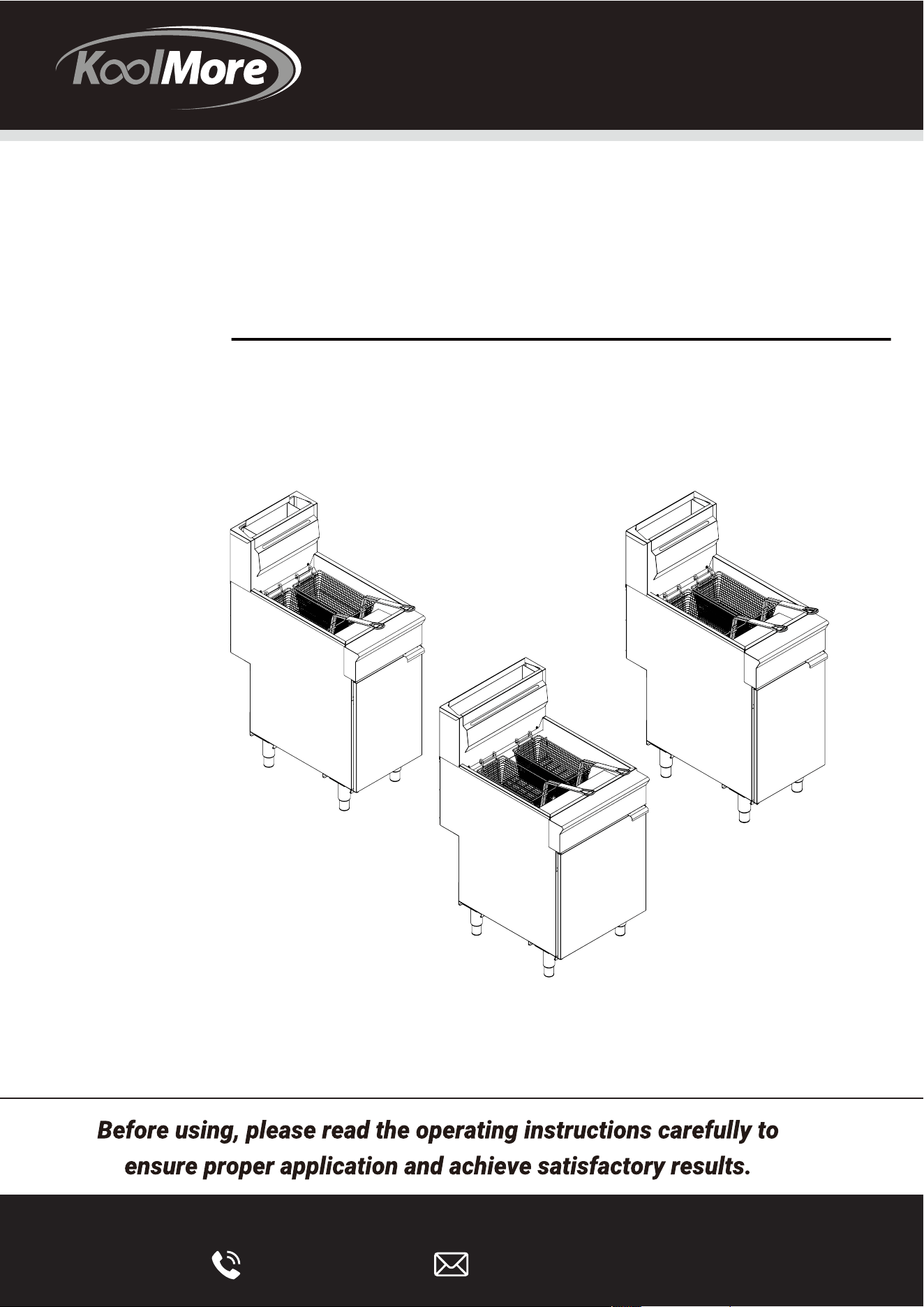
INSTALLATION MANUAL
DEEP FRYER
Models:
KM-FDF40-NG | KM-FDF40-LP | KM-FDF50-NG | KM-FDF50-LP |
KM-FDF75-NG | KM-FDF75-LP
KoolMore KoolFryer Collection
Commercial Floor Standing Fryer
KM-FDF40-NG
KM-FDF40-LP
KM-FDF50-NG
KM-FDF50-LP
KM-FDF75-NG
KM-FDF75-LP
Stay informed with the latest information
for your KoolMore KoolFryer Appliance.
Scan the QR code above to access the most recent user manual
on our website, which is constantly being updated and improved.
If you need any assistance or have questions, our customer
support team is here to help.
Updated On Sep 07 2023
Version: 1.0

Your safety is our top priority. Before installing and using this equipment, please read and follow
these important warnings and guidelines:
• Flammable Materials: Do not store or use gasoline or any other flammable vapors or
liquids near this equipment, or any other similar appliances.
• Proper Installation and Maintenance: Improper installation, adjustment, alteration,
service, or maintenance can lead to property damage, injury, or even loss of life. Always
ensure that installation and maintenance are carried out by qualified professionals.
• Read Instructions Thoroughly: Before installing or servicing this equipment, thoroughly
read and understand the installation and maintenance instructions provided in this
manual.
• Compliance with Codes: Make sure the equipment is installed by a qualified installer in
accordance with all federal, state, and local codes and regulations.
• Stable Support: Never install or use the equipment without all four legs properly in place
to ensure stability and safe operation.
• Safe Location: This equipment is intended for use in non-combustible locations only. Do
not place it in areas where there is a risk of fire.
• Ventilation: Do not obstruct the flow of combustion and ventilation air around the equip-
ment to ensure proper operation.
• Avoid Liquids: Do not spray controls or the external surfaces of the equipment with
liquids or cleaning agents, as this may cause damage.
• Cool Before Cleaning or Moving: Always allow hot parts to cool down before attempting
to clean or move the equipment.
• Level Surface: Place the equipment on a flat, level surface to prevent any instability
during use.
• Gas Line Integrity: Ensure that no loose dirt or metal particles enter the gas lines of this
equipment, as they can damage the valve and affect its operation.
• Gas Odor: If you detect a gas odor, follow the instructions provided by your gas supplier.
Do not attempt to light the burner, and avoid using telephones in close proximity to the
source of the odor.
• Safety During Cooking: Never try to move the grate while cooking to prevent accidents
and burns.
Please adhere to these safety precautions to ensure the safe and proper operation of your
equipment. If you have any questions or concerns, consult with a qualified professional.
SAFETY/WARNING
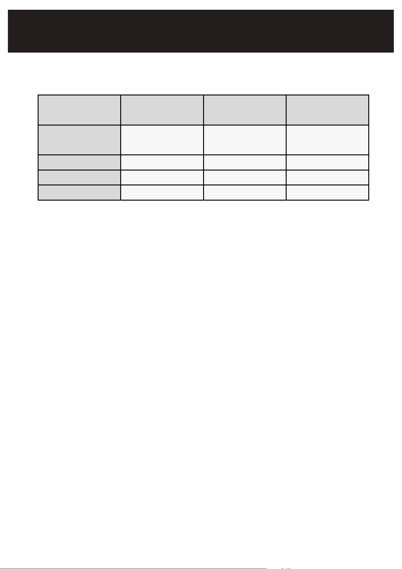
M odel No.
KM - FDF40-
NG/ LP
KM - FDF50-
NG/ LP
KM - FDF75-
NG/ LP
Dimension
(W D H)
15.5" x 30.1" x
47.0"
15.5" x 30.1" x
47.0"
20.9" x 30.1" x
47.0"
Power 90,000 BTU 120,000 BTU 150,000 BTU
Capacit y 5.3-6.3 gallons 5.9-6.9 gallons 8.7-10.1 gallons
N.W . 134.5 lbs. 145.5 lbs. 165.3 lbs.
Fry Basket Capacity:
KM-FDF40-NG/LP:
Recommended load per basket - 1.5 lbs.
KM-FDF50-NG/LP:
Recommended load per basket - 2.5 lbs.
KM-FDF75-NG/LP:
Recommended load per basket - 3.0 lbs.
PRODUCT PARAMETERS TABLE

INSTALLATION
Setup:
• Remove all packaging material, tape, and protective plastic from the equipment.
• Position the equipment at your desired location and height.
• Attach the four (4) legs securely to the equipment.
• Prior to use, ensure the equipment is clean and completely dry.
• Follow these steps carefully to prepare and set up your equipment for safe and effective use.
Clearances and Location:
Clearances:
▪ Ensure proper space and accessibility for appliance servicing and operation.
▪ Minimum clearance from combustible construction: 6” (15 cm) from the SIDES of the fryer, 6”
(15 cm) from the BACK of the fryer. If using factory-approved leveling legs or casters, the
fryer may be installed on combustible floors; however, using any other mounting method
voids the warranty.
▪ Minimum clearance from noncombustible construction: 0” from the SIDES of the fryer, 0”
from the BACK of the fryer.
▪ Maintain a 16” (41 cm) clearance between the fryer and any open-top flame units or
unshielded heaters and burners. Consider using a Flame Guard if allowed by local codes and
officials.
Location:
▪ Installation must comply with local building codes and receive approval from authorized
building and fire inspectors before starting fryer operation.
▪ Install the fryer in an area with sufficient air supply for complete tube burner gas combustion.
▪ Do not obstruct the flow of the appliance’s combustion and ventilation air.
▪ Provide adequate clearance for air openings into the combustion chamber.
▪ Avoid fans blowing directly onto the fryer, which can impact burner or pilot valve
performance.
▪ Ensure proper room ventilation ducts to avoid any direct airflow on the appliance.
▪ Ensure the floor allows the fryer to sit level and securely for proper operation, service, and
cleaning.
▪ No electrical connection is needed; the standard control scheme uses millivolt components
and possibly a piezo igniter.
▪ If mobile, use an approved quick connect gas supply hose with a restraint cable to prevent
tipping and hot oil hazards.
▪ Install the fryer under an approved, operational, and properly sized ventilation exhaust hood
Before installing the fryer, verify that the type of gas (natural or liquid propane [LP]) agrees with the
specifications on the fryer data plate. The fryer data plate is located on the inside of the door panel.
Make
sure the fryer is configured for the proper elevation (height above sea level) of the facility.
Record the gas fryer model and serial number for future reference in the space provided below. This
information is on the fryer data plate. Also record the installation date.
Fryer Model No: ______________Installation Date:______________ Serial No:________________
▪ with a minimum 6” overhang surrounding the fryer. A make-up air style is suggested, with a
built-in and tested fire protection system (e.g., Ansul™).
▪ The appliance’s electrical schematic diagram is located inside the door.
▪ Do not directly connect the fryer flue or exhaust to the ventilation hood.
▪ Ensure the hood grease filters are at least 18” above the fryer exhaust flue.
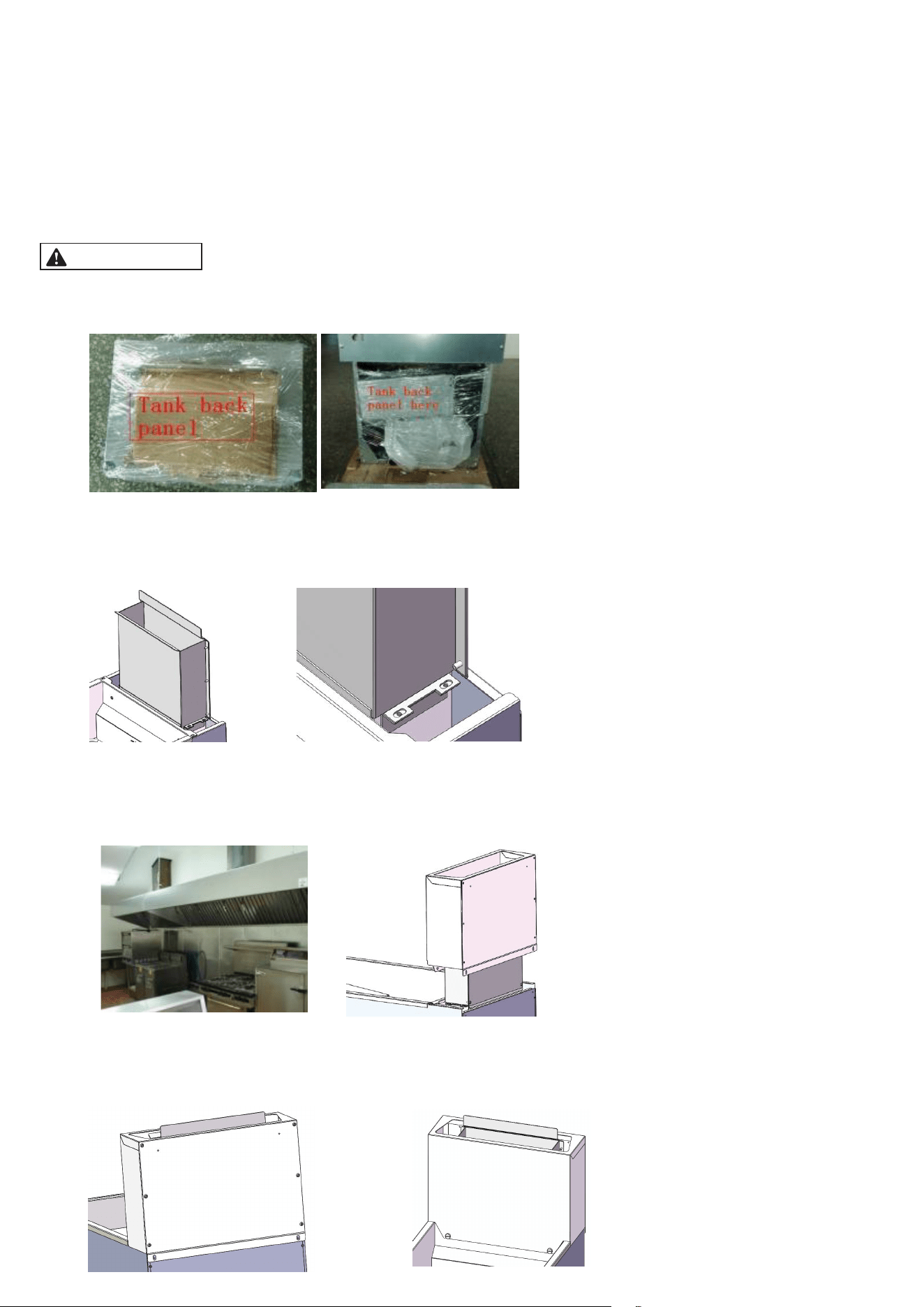
FLUE INSTALLATION:
BEFORE USING FRYER INSTALL AND ASSEMBLE THE 10-5/8” FLUE AND
DEFLECTOR PLATE TO THE FRYER.
1. Unpack the flue box and flue wrap
2. Place the inner flue box over the flue and secure it with four self-tapping screws using a
5/16” socket
3. Slide the flue wrap over the inner flue [ Ensure the fryer is properly positioned under the
hood with proper overhang on all sides of the appliance – code requires ≥ a 6” hood overhang
distance]
4. Secure it with two self-tapping screws on the back and then secure it with two slotted head
M5 screws from front.

Codes and Standards:
The fryer installation must adhere to all relevant national and local codes, regulations, and ordi-
nances. A final inspection for building and fire protection compliance is necessary and should be
approved before putting the new fryer into service.
In the United States:
▪ Comply with state and local codes. In the absence of local codes, follow the National Fuel
Gas Code, ANSI-Z223.1/NFPA #54 (latest edition). Copies are available from The American
Gas Association Accredited Standards Committee Z223, @ 400 N. Capital St. NW, Washing-
ton, DC 20001, the Secretary Standards Council, NFPA, 1 Batterymarch Park Quincy, MA
02169-7471, or online.
▪ Refer to NFPA Standard #96 for Vapor Removal from Cooking Equipment, latest edition.
Obtain it from the National Fire Protection Association, Batterymarch Park, Quincy, MA.
▪ Consider ANSI standards Z 21.69 and Z 21.41 if the fryer is mounted on casters for mobility
during cleaning and servicing. Ensure the fryer remains stable and level in all locations where
it operates or undergoes maintenance. If the unit is disconnected from its restraint cable,
reconnect it before putting the appliance back into service.
▪ In the Commonwealth of Massachusetts, gas appliances vented through a ventilation hood
or exhaust system with a damper or power means of exhaust must comply with the com-
monwealth’s regulation standard, number 248 CMR.
In Canada:
▪ Follow all applicable local codes.
▪ Comply with the CAN/CSA-B149.1 Natural Gas and Propane Code Installation (latest edition).
You can obtain this code from the Canadian Gas Association at 350 Sparks Street, Ottawa,
Ontario Canada K1R 7S8.
▪ Reference the CSA C22.1 Canadian Electric Code, available from L4W 5N6.
▪ Consider CSA Standards 6.16 and 6.9 if the fryer is mounted on a caster set approved by the
manufacturer or distributor, allowing mobility (refer to the following comments regarding the
use of a restraint cable).
ASSEMBLY:
The fryer must be properly secured to prevent tipping and splashing of hot liquid. This can be
achieved through various means, such as installing it alongside other appliances, placing it in an
alcove, or using restraining cables if it's on casters for mobility. If the unit needs to be discon-
nected from its restraint cable for any reason, it must be reconnected before being put back into
service.
FLUE EXHAUST GAS:
Comply with Vapor Removal from Cooking Equipment, ANSI-NFPA Standard #96 (latest edition),
available from the National Fire Protection Association, Batterymarch Park, Quincy, MA 02269.
▪
▪ Locate the fryer under a hood with adequate connection to an exhaust duct. The hood must
extend 6” (15 cm) beyond fryer on both sides as well as in front of and behind the fryer if
mounted against a back wall or in an island cooking bank set-up.
▪ Clearance above the fryer should be adequate for all combustion byproducts to be removed

▪ efficiently and safely without creating a potential fire hazard.
▪ No structural material on the fryer or its flue chimney including physical alterations should be
made so it can be placed under an approved exhaust hood with fire protection.
▪ An 18” (46 cm) minimum clearance should be maintained between the flue vent and the
grease removal filters of the hood venting system.
▪ Never make flue connections directly between the fryer and exhaust hood.
▪ Do not obstruct the flow of the gases from the appliance. Proper air balance should be main-
tained in the room. The exhaust system must meet all applicable local air exchange require-
ments, regulations, ordinances, and building codes.
▪ Ensure that your ventilation system does not cause a down draft at the fryer’s flue opening.
Down draft will not allow the fryer to exhaust properly and will cause overheating, which may
cause permanent damage. Damage caused by down drafts aren’t covered under the equip-
ment warranty.
▪ Never allow anything to obstruct the flue or ventilation exiting from the fryer flue.
▪ NEVER put anything on top of the flue open area which may impact the exhaust gas flow.
CONNECTION GAS:
All gas supply connections and any pipe joint compound must be resistant to the action of
propane gases or any other reasonable corrosion causes or catalysts.
▪ The gas inlet is located on the lower rear of the fryer. Codes require that a gas shutoff valve
be installed in the gas line ahead of the fryer. Installing the fryer and gas plumbing safely in
accordance with the local codes and manufacturer directives including an approved pressure
regulator is the purchaser’s (end user’s) responsibility not the fryer manufacturer or distribu-
tor.
▪ The gas supply line must be at least the equivalent of ½” (12.7 mm) iron pipe for single units
and 1-1/4” (31.75 mm) for batteries. If using the optional quick-disconnect flex hose, ¾” (19
mm) iron pipe feeding it is appropriate for single fryer applications.
▪ Each fryer is equipped with a ½” – ¾” coupling that facilitates the proper gas supply line
connection using approved piping and possibly an approved quick disconnect hose with its
required restraint cable hook-up to hold it in position that is required by code if on casters (a
mobile appliance set-up).
▪ Make sure the pipes are clean and free of obstructions, dirt, and piping compound. A battery
set up may require one or two connections of appropriate size for the gas requirement to
properly supply each gas cooking appliance in that battery line-up.
▪ Prior to lighting, check all joints in the gas supply line for leaks.
▪ Use soap and water solution. Do not use an open flame.
▪ After piping has been checked for leaks, fully purge gas pipes to remove any trapped air in
the line prior to bringing the fryer on line and into service.
GAS PRESSURE (ALL MODELS): Natural Gas, Town Gas or LP {Liquid Propane Gas}
▪ Set gas pressure at 4” W.C. (Water Column) for natural gas and 10” W.C. for LP gas.
▪ If incoming pressure exceeds ½ PSI, install an additional pressure regulator.
▪ The nameplate indicates the type of gas fuel supply (LP or Natural Gas).
▪ Gas piping should be performed by a licensed plumber and approved by local authorities.
TESTING THE GAS SUPPLY PIPING CONNECTION

When test pressures exceed ½ PSI (3.45 kPa), the fryer and its individual shutoff valve must be
disconnected from the gas supply piping system.
When test pressures are ½ PSI (3.45 kPa) or less, the fryer must be isolated from the gas supply
piping system by closing its individual shutoff valve.
If any leaks must be repaired, ensure the line is free of any residual gas and then execute the
needed remedial action safely and properly to conform to the prevailing codes and ordinances.
MOBILE FRYER INSTALLATION:
Mobile fryers may not come with approved casters, a quick disconnect supply hose, or a secure
restraining device. Typically, these fryers are equipped with leveling legs for stationary setups,
allowing a secure connection to gas piping.
For installations that require casters, follow separate instructions included with caster kits:
▪ Gas Connector: Ensure the installation includes a gas connector that complies with the
current Standard for Connectors for Movable Gas Appliances, ANSI Z-21.69, or Connectors
for Movable Gas Appliances, CAN/CGA-6.16.
▪ Quick-Disconnect Device: Use a quick-disconnect device that adheres to the Standard for
Quick-Disconnect Devices for Use with Gas Fuel, ANSI Z-21.41, or Quick-Disconnect Devices
for Use with Gas Fuel, CANI-6.9.
▪ Restraining Device: Install a restraining device to prevent any strain on the gas line or
quick-disconnect hose. Attach this device to the mounting system or cutout on the fryer’s
back panel.
▪ If it's necessary to disconnect the restraining device for servicing or cleaning the unit, always
remember to reconnect the restraining device after placing the fryer back into its original
position.
▪ The fryer must be used with an approved restraint cable and quick-disconnect gas supply
flexible hose connector that complies with all applicable codes.
▪ Ensure that the fryer setup has a proven means of restraining to prevent transmitting strain to
the restraining connector. For more details, refer to the illustration above for a better under-
standing of this requirement.
▪ The fryer should be installed with the casters provided by the manufacturer or approved by
the manufacturer.
▪ If the restraint cable needs to be disconnected for any reason, the gas supply should be
turned off first. Then, reconnect the restraint cable before returning the appliance to normal
operation.
Manufacturers or distributors often offer approved mobile gas appliance installation kits. These
kits include proper casters (usually with 2 brakes), an approved quick disconnect hose, and a
rated restraining cable. Using such kits ensures compliance with safety standards and maintains
the factory equipment warranty.

If you need to disconnect the restraining device for servicing or cleaning, remember to reconnect
it before returning the appliance to its original position.
LEVELING THE FRYER
1. Check the fryer's level by placing a "level" on top of it after connecting all gas components.
Ensure that the fryer is level both front-to-back and side-to-side in its final installed position.
2. If your setup includes casters, lock the wheels once the fryer is level. Confirm that the fryer
remains stable and level as you move it to different locations for operation, cleaning, or
servicing. Be cautious when moving a full fryer, as hot oil may splash.
BEFORE FIRST USE
Cleaning: When you receive your new unit, it has undergone a factory cleaning process to remove
visible dirt, oil, grease, and other residues from the manufacturing process. However, before
using it for any food preparation, it's essential to follow these steps:
1. Thoroughly wash all surface parts and the interior of the tank with hot soapy water. This will
help remove any film residue, dust, or debris that may remain.
2. It is recommended to perform a fryer boil-out with a cleaning compound. This procedure
typically takes place at the factory before the unit is crated and shipped through regular
distribution channels.
3. Please avoid using cleaners that contain chlorine or sulfates/sulfides, as they may not be
suitable for your fryer.
4. Additionally, wash any accessories that were shipped with the unit.
5. After cleaning, rinse both the fryer and its accessories thoroughly, and ensure the fryer is
drained completely.
6. Finally, use a soft, clean cloth to wipe the tank entirely dry.
OPERATION
Operation Warnings
Burn Hazard: Exercise caution when operating, cleaning, or servicing the fryer as hot oil and parts
can cause burns.
Spill Risk: Avoid severe burns by not moving the fryer without draining all frying compound from
the tank.
Power Outage: Do not use the fryer during a power outage. Ensure a stable power supply before
operation.
Do not touch any hot surfaces ! Do not operate unattended !
Please adhere to these warnings for your safety when operating the fryer.
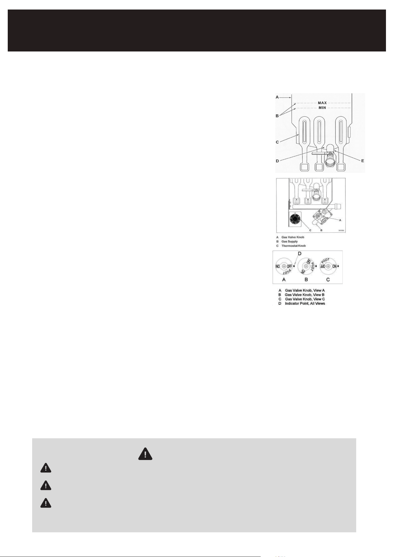
Filling the Tank with Shortening
WARNING: Solid shortening must NOT be used with fryers. Melting
solid
shortening will damage the tank and void your warranty
1. Ensure the drain valve is closed.
2. Fill the fryer tank with liquid shortening.
3. Maintain the shortening level between the "min" and "max" lines in
the fryer tank.
4. Be aware that shortening will expand when heated, so do not
exceed the MAX line.
5. Add fresh shortening as needed to maintain the oil level.
Lighting the Pilot
1. Open the fryer door.
2. Turn the thermostat OFF, located behind the door.
3. Push and turn the gas control valve knob to OFF. Wait for 5 min-
utes to allow any unburned gas to vent.
4. Push and turn the gas control valve knob to the "L" in PILOT.
5. While continuing to hold the knob in, use a flame to light the pilot.
Keep the knob depressed until the pilot remains lit when released. If
the pilot does not stay lit, repeat steps 3 through 5.
6. Depress and turn the gas control knob to ON.
7. In case of a gas supply interruption, repeat steps 2 through 6.
Turning On the Fryer
1. Set the temperature knob to your desired temperature.
2. Once the set temperature is reached, the thermostat will shut off the gas flow to the burners.
3. The pilot light will remain on, and the burners will cycle on and off to maintain the set tempera-
ture.
Turning Off the Fryer
1. Turn the thermostat OFF.
2. To keep the pilot light on, turn the gas valve to "L" in Pilot.
3. To shut off all gas to the system, including the pilot, turn the gas valve knob to OFF.
Follow these steps for safe and proper operation of your fryer.

BASIC FRYING INSTRUCTIONS
Set the desired temperature and allow shortening to heat up to that temperature.
Fry items that are of similar size to ensure equal doneness.
Drain or wipe dry raw or wet foods to minimize splatter when lowering into hot oil.
Add fresh shortening as needed top maintain the shortening level between the recommended
(embossed) minimum and maximum fill level (volume) lines.
FRY BASKET GUIDELINES
Don’t overfill baskets. (See table for recommended basket capacities below) Carefully lower each
basket into the hot oil to minimize turbulence and splatter to meet the customer demand.
When frying doughnuts and fritters, turn product only once during frying.
When cooking French fries or onion rings, shake the basket several times.
Batter-covered foods should be dropped carefully, one by one, into shortening or basket (If a basket
is
used, first dip the basket into the oil to reduce batter-build up on basket surfaces.)
When frying is completed, remove basket or product. Hang basket on the rear basket hanging plate
allowing he excess oil to flow back into the fry vat (kettle/pot/tank).
FRY BASKET CAPACITY
For the GFF3-40 and GFF4-50 models: Recommended maximum pounds per basket of frozen
French fries
are 1.5 lbs. (0.7 kg). {NEVER put more than 2 lb of frozen fries into any one basket}
For Model GFF5-70 fryer, its recommended maximum frozen fry load is 3 pounds per basket (1.4
kg).

TROUBLE SHOOTING
Cleaning Warnings
Hot oil and hot parts can cause burns. Use care when operating,
cleaning, and servicing the fryer.
To maintain cleanliness and increase service life, the fryer should be
cleaned daily. Do not immerse in water or any other liquid, if liquid enters the electrical
compartment it may cause a short circuit or electrical shock.
Do not use chlorine or sulfate/sulfide cleaners.
Overheating Shutdown
If the shortening overheats, a high-temperature shutoff will turn off the gas valve and extinguish the
pilot.
Do not attempt to relight the pilot if the shortening temperature is above 300°F (149°C) after an
overheating shutdown.
Extended Shutdown
Turn the thermostat knob to OFF.
Push in the pilot knob and turn to OFF.
Drain the fryer completely following the "Draining the Oil" instructions.
Clean the fryer as per the "Cleaning" guidelines.
Turn off the main gas shutoff valve.
Extending Shortening Life
To extend the life of shortening, follow these guidelines:
• Avoid salting foods over the fryer.
• Use high-quality shortening.
• Daily filtration of shortening is recommended.
• Replace shortening if it develops an undesirable flavor.
• Maintain equipment and surroundings clean, using tank covers when not in use.
• Set the thermostat correctly.
• Remove excess moisture and food particles from items before frying.
• Use a fitted tank cover to shield oil from light and oxygen.
Draining the Oil
1. Turn the thermostat knob to OFF.
2. Insert the drain extension into the drain valve and tighten it by hand.
3. Direct the drain extension into the filtering device you intend to use.
4. Slowly open the drain valve to allow oil to flow into the filter pan, then fully open it.
5. After emptying the fry tank, use the tank brush to remove any remaining debris.
6. Close the drain valve.
7. Refill the tank with new shortening, filling to at least the MIN level but no higher than halfway
between MIN and MAX, considering oil expansion when heated.
8. After filling with new oil, set the thermostat knob to the desired temperature. The burners will
heat the oil.
Problem Pos s ible Caus es
No Heat - Thermostat dial not turned on.
- Pilot not lit.
- Gas supply not turned on.
- Loose wire connections (call service).
- Wire connections need cleaning (call service).
- Faulty thermopile (call service).
Ins ufficient or
Exces s ive Heat
- Thermostat dial not set to desired
temperature.
- High limit tripped (call service).
- Temperature probe issue (call service).
Tank Will Not
Drain
- Shortening too cold.
- Drain pipe clogged with debris.

MAINTENANCE
Gas Fryer Maintenance & Sanitation Calendar
Daily Tasks:
1. Clean the fryer's exterior surfaces with a damp cloth using warm water and mild soap.
Remove discolorations and grime using non-metallic scouring pads.
2. Empty the tank into an approved hot oil storage vessel while filtering the oil at about 275°F
(135°C).
3. Clean the crumbs and debris from the cold zone and tank walls using a brush and clean
cloth.
4. Refill the fry tank with fresh oil after testing it for quality. Discard old oil when necessary.
5. Clean and sanitize the area around the fryer.
6. Wash or wipe the basket hanging plate and clean the fry baskets and fryer rack.
7. Ensure these daily tasks are executed and reviewed by shift or general managers.
Weekly Tasks:
1. Clean behind and under the fryer, as well as its sides.
2. Confirm the fry vat temperature control is accurate and doesn't need calibration.
3. Check the burner flame for appearance and calibration.
Monthly Tasks:
1. Perform a fry tank boil-out.
2. Test fryer warm-up time.
3. Check the burner orifices and re-tune.
4. Run a burner test to confirm gas consumption is within 2% of the original value.
5. Inspect the burner baffles for condition and thickness; replace if necessary.
6. Have the unit inspected by a factory-trained service technician.
7. Inspect safety apparel, accessories, and fry baskets; replace elements showing excessive
wear or performance issues.
8. Validate the calibration of the thermometer used to calibrate the thermostat.
9. Use a clean-out rod to clear the drain and record the measured test results for future refer-
ence.
Semi-annual Tasks:
1. Confirm the high limit and pilot thermopile safeties are functional.
2. Clean the burner orifices and re-tune.
3. Run a burner test and confirm gas consumption.
4. Inspect the burner baffles, safety apparel, and accessories.
5. Replace elements showing excessive wear or performance issues.
6. Validate the calibration of the thermometer used to calibrate the thermostat.
7. Run a drain time test.
8. Record the measured test results for future reference.
Boil Out Procedure (Weekly or as Required):
1. Drain the tank as described under "Draining the Oil."
2. Flush out scraps and sediment using warm shortening and a tank brush. Drain thoroughly.
3. Close the drain valve and fill the tank with water.
4. Use a low-foaming cleaner/degreaser to clean the fry tank. Follow package instructions.
5. Add commercial boil-out solution to the tank (solution level between MIN and MAX tank
levels).
6. Set thermostat to recommended solution temperature (not exceeding 210°F). Simmer for
15-20 minutes.
7. Drain the cleaning solution.
8. Close the drain valve and refill the tank with water. Add 1 cup (1/4 L) of vinegar or citric acid
solution to neutralize alkaline residue (solution between MIN and MAX tank levels).
9. Drain the tank as described under "Draining the Oil."
10.Rinse the tank thoroughly with clear, hot water and ensure all traces of cleaner are removed.
Dry the tank thoroughly.
11.Close the drain valve and add shortening. Follow the "Filling the Tank with Shortening" proce-
dure in this manual.
The fryer is now ready for use.

LIMITED WARRANTY
Koolmore Supply, Inc. extends a limited warranty to the original purchaser, guaranteeing that this Koolmore
product is free from manufacturing defects in material or workmanship for one year from the date of
purchase.
Should you discover any such defect within the warranty period, Koolmore Supply, Inc., reserves the right to
repair or replace the product without charge, or to cover the cost of replacement parts and repair labor needed
to correct defects present at the time of purchase or resulting from regular usage, when the appliance has been
installed, operated, and maintained as per the instructions provided.
At its sole discretion, Koolmore Supply Inc. may decide to replace the product. In such an event, your replace-
ment appliance will carry the warranty for the remaining term of the original unit's warranty period.
This warranty is valid exclusively to the original purchaser of the product and only applicable within the United
States. The warranty commences from the date of original consumer purchase. Proof of the original purchase
date will be required to obtain service under this warranty.
Under this limited warranty, your sole and exclusive remedy will be product repair, as outlined above. All
services must be provided by a Koolmore-designated service company.
To claim warranty or request repair service:
Email suppor[email protected]. Please include your name, address, phone number, warranty repair request,
and a copy of your proof of purchase receipt. Alternatively, visit koolmore.com and use the contact us page. A
Koolmore customer service representative will promptly arrange service for your appliance.
We thank you for choosing Koolmore.
WARRANTY EXCLUSIONS
This limited warranty will not cover:
1. Failure of the product to perform during power failures or interruptions,
or due to inadequate electrical service.
2. Damage incurred during transportation or handling.
3. Damage caused by accidents, vermin, lightning, winds, fire, floods, or acts of God.
4. Damage resulting from accidents, alterations, misuse, abuse, improper installation, repair, or mainte-
nance. This includes using any external device that alters or converts the voltage or frequency of
electricity.
5. Unauthorized product modifications, repairs by unauthorized centers, or use of non-approved
replacement parts.
6. Abnormal cleaning and maintenance not aligned with the user's manual.
7. Use of incompatible accessories or components.
8. Any costs associated with repairs or replacements under these excluded circumstances shall be the
responsibility of the consumer.
WARRANTY