
AFC Image Controller
V1.0 User Guide

Table of contents
1. Introduction . . . . . . . . . . . . . . . . . . . . . . . . . . . . . . . . . . . . . . . . . . . . . . . . . . . . . . . . . . . . . . . . . . . . . . . . . . . . . . . . . . . Ê2
1.1. Attention . . . . . . . . . . . . . . . . . . . . . . . . . . . . . . . . . . . . . . . . . . . . . . . . . . . . . . . . . . . . . . . . . . . . . . . . . . . . . . . . . Ê2
1.2. What AFC Image Controller Can Do . . . . . . . . . . . . . . . . . . . . . . . . . . . . . . . . . . . . . . . . . . . . . . . . . . . . . . . . . . . Ê3
1.3. Operating Environment/Installation . . . . . . . . . . . . . . . . . . . . . . . . . . . . . . . . . . . . . . . . . . . . . . . . . . . . . . . . . . . Ê4
1.4. AFC Image Component System Block Diagram . . . . . . . . . . . . . . . . . . . . . . . . . . . . . . . . . . . . . . . . . . . . . . . . . Ê5
2. Preparation . . . . . . . . . . . . . . . . . . . . . . . . . . . . . . . . . . . . . . . . . . . . . . . . . . . . . . . . . . . . . . . . . . . . . . . . . . . . . . . . . . . . Ê6
2.1. System Setup and Connections between Devices . . . . . . . . . . . . . . . . . . . . . . . . . . . . . . . . . . . . . . . . . . . . . . . Ê6
3. Basic Usage . . . . . . . . . . . . . . . . . . . . . . . . . . . . . . . . . . . . . . . . . . . . . . . . . . . . . . . . . . . . . . . . . . . . . . . . . . . . . . . . . . . Ê8
3.1. Synchronization method with AFC Image components inside DME . . . . . . . . . . . . . . . . . . . . . . . . . . . . . . . . Ê8
3.2. Setup of speakers to be connected/Zone settings. . . . . . . . . . . . . . . . . . . . . . . . . . . . . . . . . . . . . . . . . . . . . . . Ê8
3.3. Input system setup . . . . . . . . . . . . . . . . . . . . . . . . . . . . . . . . . . . . . . . . . . . . . . . . . . . . . . . . . . . . . . . . . . . . . . . . . Ê8
4. Names and Functions of Respective Parts. . . . . . . . . . . . . . . . . . . . . . . . . . . . . . . . . . . . . . . . . . . . . . . . . . . . . . . . . . Ê9
4.1. Welcome Screen . . . . . . . . . . . . . . . . . . . . . . . . . . . . . . . . . . . . . . . . . . . . . . . . . . . . . . . . . . . . . . . . . . . . . . . . . . . Ê9
4.2. Common to All Windows . . . . . . . . . . . . . . . . . . . . . . . . . . . . . . . . . . . . . . . . . . . . . . . . . . . . . . . . . . . . . . . . . . . Ê10
4.3. Controls Window . . . . . . . . . . . . . . . . . . . . . . . . . . . . . . . . . . . . . . . . . . . . . . . . . . . . . . . . . . . . . . . . . . . . . . . . . Ê14
4.4. Scenes Window. . . . . . . . . . . . . . . . . . . . . . . . . . . . . . . . . . . . . . . . . . . . . . . . . . . . . . . . . . . . . . . . . . . . . . . . . . . Ê19
4.5. Reverb Window . . . . . . . . . . . . . . . . . . . . . . . . . . . . . . . . . . . . . . . . . . . . . . . . . . . . . . . . . . . . . . . . . . . . . . . . . . . Ê21
4.6. System Window . . . . . . . . . . . . . . . . . . . . . . . . . . . . . . . . . . . . . . . . . . . . . . . . . . . . . . . . . . . . . . . . . . . . . . . . . . Ê27
4.7. About Window. . . . . . . . . . . . . . . . . . . . . . . . . . . . . . . . . . . . . . . . . . . . . . . . . . . . . . . . . . . . . . . . . . . . . . . . . . . . Ê35
5. Snapshot Integration with DME . . . . . . . . . . . . . . . . . . . . . . . . . . . . . . . . . . . . . . . . . . . . . . . . . . . . . . . . . . . . . . . . . . Ê36
5.1. SnapShot Linking Procedure. . . . . . . . . . . . . . . . . . . . . . . . . . . . . . . . . . . . . . . . . . . . . . . . . . . . . . . . . . . . . . . . Ê36
5.2. How to Change Number of In/Out of Placed AFC Image Component . . . . . . . . . . . . . . . . . . . . . . . . . . . . . . Ê37
Table of contents
1 | AFC Image Controller V1.0 User Guide

1. Introduction
Thank you for downloading Yamaha AFC Image Controller.
AFC Image Controller is application software for Windows and macOS used to control the AFC Image sound
image control system that runs on Yamaha or NEXO DME series signal processors. AFC Image is a sound image
control system that realizes three-dimensional sound image localization using the object-based audio method. It
enables the provision of immersive sound experiences in a variety of applications, including musicals, theatrical
plays, operas, concerts, and installations.
1.1. Attention
• All copyrights of this software and user guide are owned by Yamaha Corporation.
• This software and user guide may not be reproduced or modified in whole or in part without permission.
• Please note that we are not responsible for any results or effects of using this software or user guide.
• All illustrations and screens shown in this user guide are for instructional purposes only. Therefore, the
actual specifications may differ.
• Windows is a registered trademark of Microsoft Corporation in the United States and other countries.
• Be aware of copyrights when using audio files for commercial purposes. Copyright infringement is
prohibited by law.
• Company names and product names mentioned in this document are trademarks or registered
trademarks of their respective companies.
• The application software may be upgraded without prior notice for improvement purposes. The latest
application software can be downloaded from the Yamaha Pro Audio site.
https://www.yamahaproaudio.com/
1. Introduction
AFC Image Controller V1.0 User Guide | 2

1.2. What AFC Image Controller Can Do
• AFC Image Controller can control the parameters of the AFC Image components placed inside the DME
series. The sophisticated GUI allows for precise and quick control of the sound image by manipulating
sound objects and adjusting the sound image size.
• The three-dimensional sound image localization can be controlled by placing sound objects and speakers
at any positions on the Cartesian coordinates (X, Y, Z).
• This software can control the parameters of the 3D reverb effect, which realizes the reverb according to
the sound object position.
• You can save and recall parameters of sound objects and 3D reverb effects in Scene data.
• This software can adjust the coordinates of each speaker, as well as the equalizer and delay.
• You can set "speaker zoning" to play sound objects through specific groups of speakers. You can also set
a rendering area that converts panning operations in logical coordinates on a Digital Audio Workstation
(DAW) or mixing console into any shape in real space.
• This software supports external control via the Open Sound Control (OSC) protocol and ADM-OSC.
• A single AFC Image component inside the DME processor can be operated from up to eight computers.
1. Introduction
3 | AFC Image Controller V1.0 User Guide
1.3. Operating Environment/Installation
1.3.1. Software operating environment
OS
Windows 11、Windows 10
CPU 2 GHz or faster Intel 64-compatible processor
Memory 4 GB or more
Storage 1 GB or more of free space
Display 1280×1024 pixels
Other Equipped with a mouse or other pointing device and Ethernet (1000BASE-
T/100BASE-TX)
OS
macOS 13 / 14 / 15(Intel/Apple silicon)
CPU 2 GHz or faster Intel Core family processor, Apple Silicon
Memory 4 GB or more
Storage 1 GB or more of free space
Display 1280×1024 pixels
Other Equipped with a mouse or other pointing device and Ethernet (1000BASE-
T/100BASE-TX)
1.3.2. Installing AFC Image Controller
Download the AFC Image Controller installer from the Yamaha Pro Audio site.
There is a link on the application page.
https://www.yamahaproaudio.com/
•
Windows
Unzip the downloaded compressed file and follow the instructions of the installer to install the software.
•
macOS
Unzip the downloaded compressed file and install the software by following the setup dialog.
1. Introduction
AFC Image Controller V1.0 User Guide | 4
1.4. AFC Image Component System Block Diagram
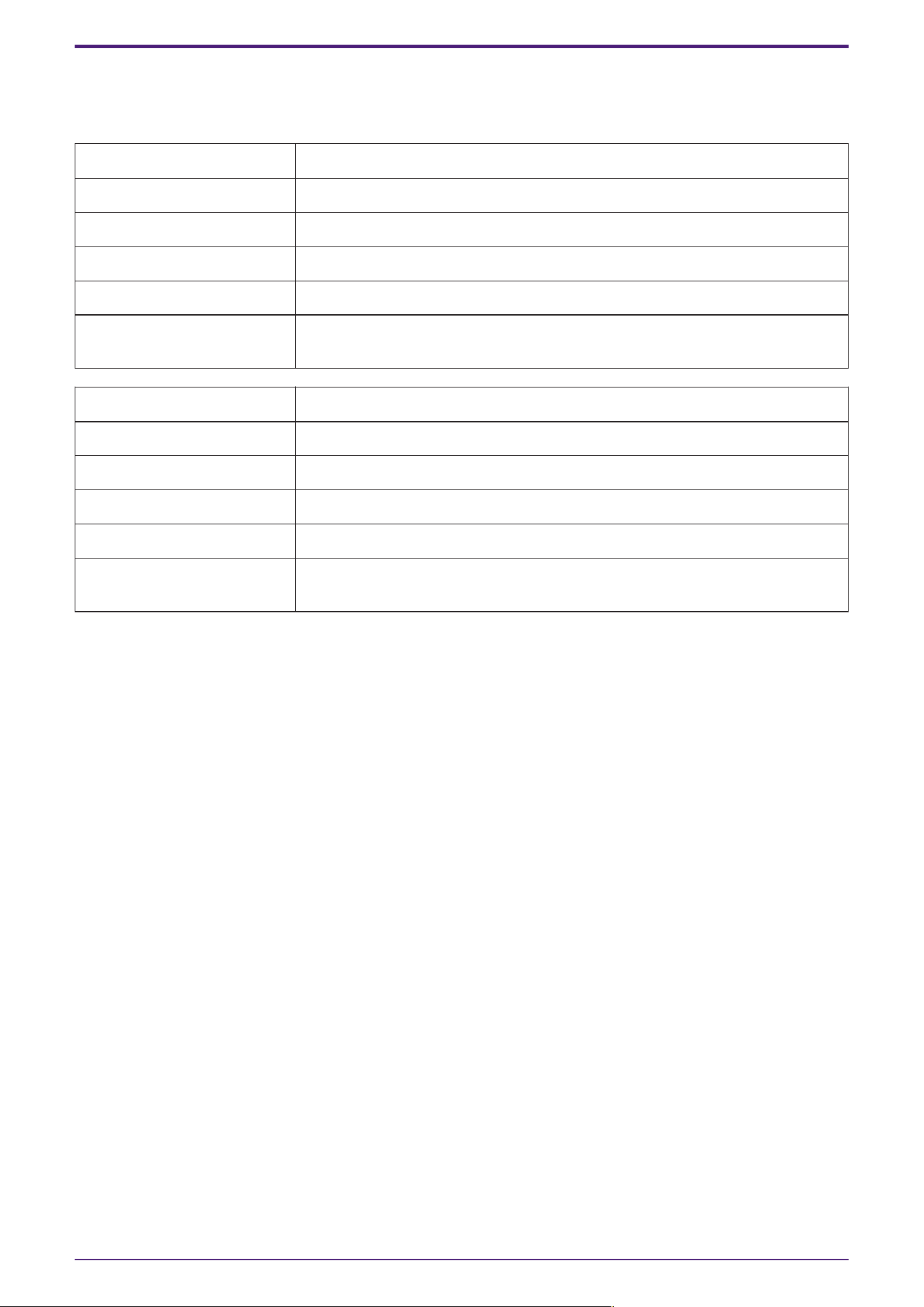
• Object Input: Receives input signals from other audio components.
• OBA (Object Based Audio) Renderer: Using the object-based audio method, the renderer calculates the
output signals to each speaker based on the position information of the sound object in three-dimensional
space.
• 3D Reverb: Processes a reverb effect that reproduces the reflection and reverberation of sound in three-
dimensional space based on the sound object position.
• SubSpeaker Renderer: Calculates the output signals of the selected sound object to speakers in a
speaker group other than the assigned speaker zone.
• Oscillator: Generates signals such as sine waves and noise.
• Speaker Out: Sends the audio signals processed by the OBA Renderer and 3D Reverb to each speaker.
• SubSpeaker Out: Sends audio signals to the sub speaker.
• AUX Send/AUX Out: Mixes in mono the input signals of the selected sound object and outputs them for
purposes such as monitoring or LFE (Low Frequency Effect).
• Oscillator Reference Out: Outputs the original signals of signals generated by Oscillator. The original
signals can be used to measure the transfer function in speaker tuning.
1. Introduction
5 | AFC Image Controller V1.0 User Guide
2. Preparation
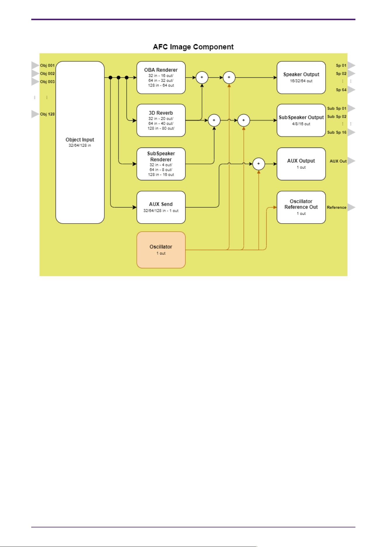
2.1. System Setup and Connections between Devices
To use AFC Image Controller online, a DME7 or DME10 (hereafter referred to as "DME") processor is required.
ProVisionaire Design sends various settings, including the AFC Image components, to the device. AFC Image
Controller controls the parameters of the AFC Image components placed in the DME processor.
2.1.1. Preparing AFC Image components
a. To place the AFC Image components inside the DME series processor, use ProVisionaire Design. If
ProVisionaire Design has not been installed, download it from the following URL.
https://www.yamahaproaudio.com/
b. Start ProVisionaire Design, select a DME processor from the Devices area, and place it by a drag-and-drop
operation. Select the required information in the dialog that appears.
c.
Double-click a DME processor and place "AFC Image" from the Components list.
The DME7 processor allows for up to 64 input channels and 32 output channels of AFC Image
components, while the DME10 processor allows for up to 128 input channels and 64 output channels of
AFC Image components.
In the dialog that appears, set the number of channel inputs and the component ID.
Set a desired component ID from the drop-down list.
d.
You can set a PIN code for the AFC Image components.
Select the placed "AFC Image component." In the Properties area that appears, turn "Access PIN" on and
set a 4-digit hexadecimal number (0000 to FFFF)(not case-sensitive).
Once you have set the PIN code, you cannot check it.
If you forget your PIN code, turn [Access PIN] off and on again. Then, set a new PIN
code.
e. Connect the audio system to the placed AFC Image component. To learn how to connect them, refer to
the ProVisionaire Design User Guide.
2. Preparation
AFC Image Controller V1.0 User Guide | 6

2.1.2. Network settings
AFC Image Controller and DME processors must be operated on the same network. In addition, since the DME
processors use Dante for audio input and output, the Dante network settings must also be configured.
For the ProVisionaire Design network settings, refer to the ProVisionaire Design User Guide.
For the DME network settings, refer to the DME7/DME10 Reference Manual.
If a DHCP server is not used, set a fixed IP address for the network card of the computer. The
recommended settings are:
IP address: 192.168.0.253
Subnet mask: 255.255.255.0
When connecting devices, we recommend using separate networks for control and for Dante.
2.1.3. License authentication
The number of input and output channels available for the AFC Image components depends on the number of
activated device licenses.
To use the AFC Image components with the DME7 processor, you will need to purchase and activate the optional
expansion kit "DEK-AFC-I" (sold separately).
With the DME10 processor, you can use one AFC Image component with 32 input channels and 16 output
channels even if the expansion kit "NX-AFC-I" is not activated.
To learn how to activate the kit, refer to the "Device Activation Guide" for each product.
2. Preparation
7 | AFC Image Controller V1.0 User Guide

3. Basic Usage
3.1. Synchronization method with AFC Image components inside DME
The state in which AFC Image components inside the DME and AFC Image Controller operate in synchronization
is called the "online state," and the state in which they are not synchronized is called the "offline state." This
section describes the procedure for synchronizing AFC Image Controller and the DME.
a. Open the Settings tab in the System window and configure the network settings.
b. Select the network interface you want to use from [Select Network Interface].
c.
Select the DME to control from [Select Device].
If you selected [Unit ID] in [Match Device by], select the connection destination DME from the [Select
Device] field.
If you selected [IP Address], enter the IP address and press the Find button. If the device is found,
information about it will be displayed.
For the DME network settings, refer to the DME7/DME10 Reference Manual.
d.
From [Select Component], select the AFC Image component you want to operate.
If a PIN code is set in ProVisionaire Design, you will need to enter the PIN code when you select Online.
If the PIN code is disabled in ProVisionaire Design, but the correct PIN code is saved in
AFC Image Controller, a PIN code input dialog may appear when you are establishing
online connection. In this case, you can clear the PIN code saved in AFC Image
Controller by simply pressing OK without entering anything.
e. Under [Sync and Connect], select [To Device/From Device] and select [Online].
To read data from a connected DME unit using AFC Image Controller, select [From
Device].
For detailed instructions, refer to section 4.6.4.
3.2. Setup of speakers to be connected/Zone settings
To use AFC Image correctly, you must enter accurate position information for the speakers you have actually
installed under System > Speakers on AFC Image Controller.
Audio output is also possible by setting a zone for the placed speakers.
A maximum of 32 zones can be created. Multiple speakers can be assigned to each zone, and sound objects to
be played can be assigned to that zone.
For detailed instructions, refer to section 4.6.
3.3. Input system setup
AFC Image Controller handles input sound sources as sound objects, and can place up to 128 sound objects.
You can freely localize the sound image by placing the sound objects in desired positions relative to the set
speaker positions.
For detailed instructions, refer to section 4.3.
3. Basic Usage
AFC Image Controller V1.0 User Guide | 8
4. Names and Functions of Respective Parts
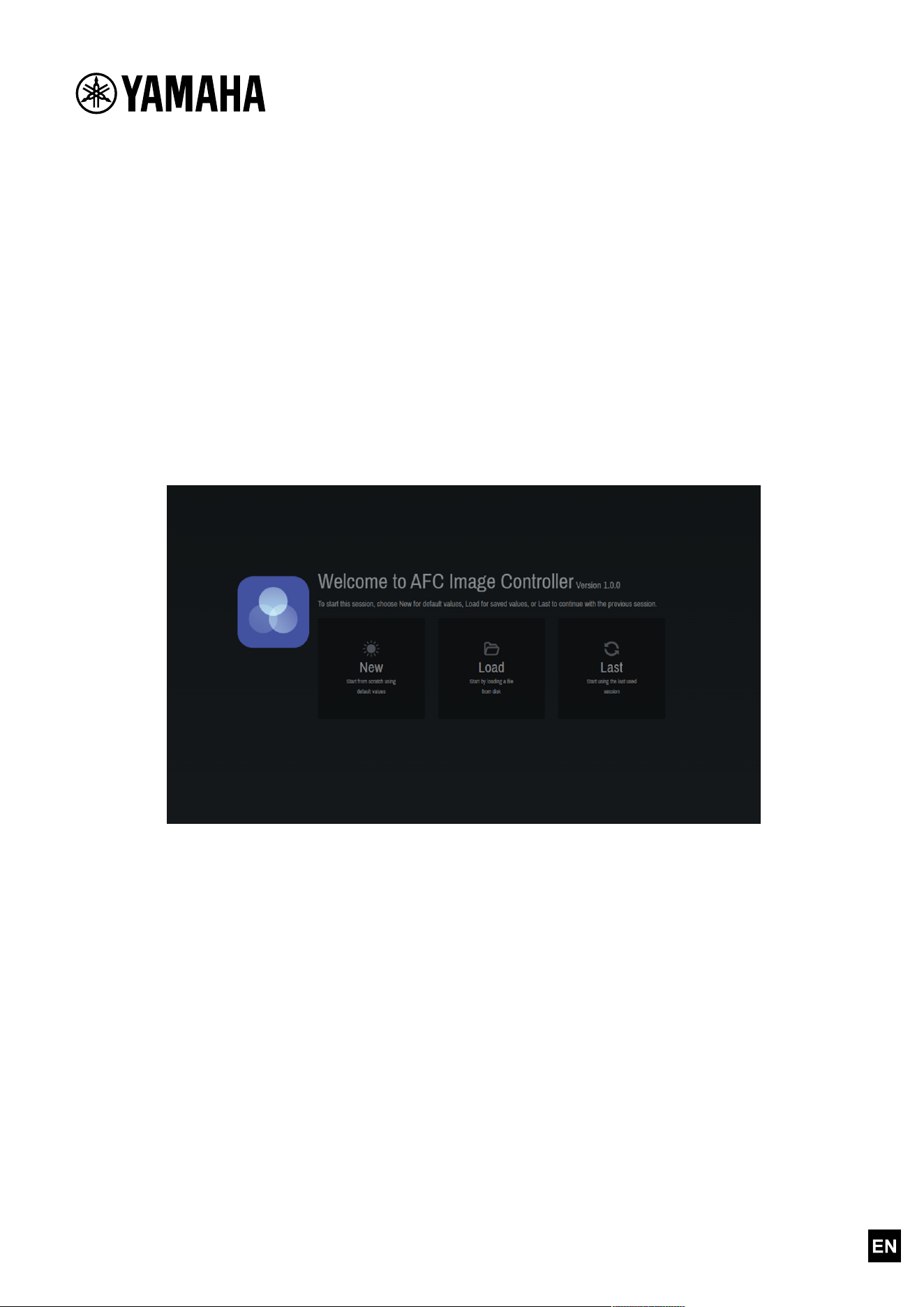
4.1. Welcome Screen
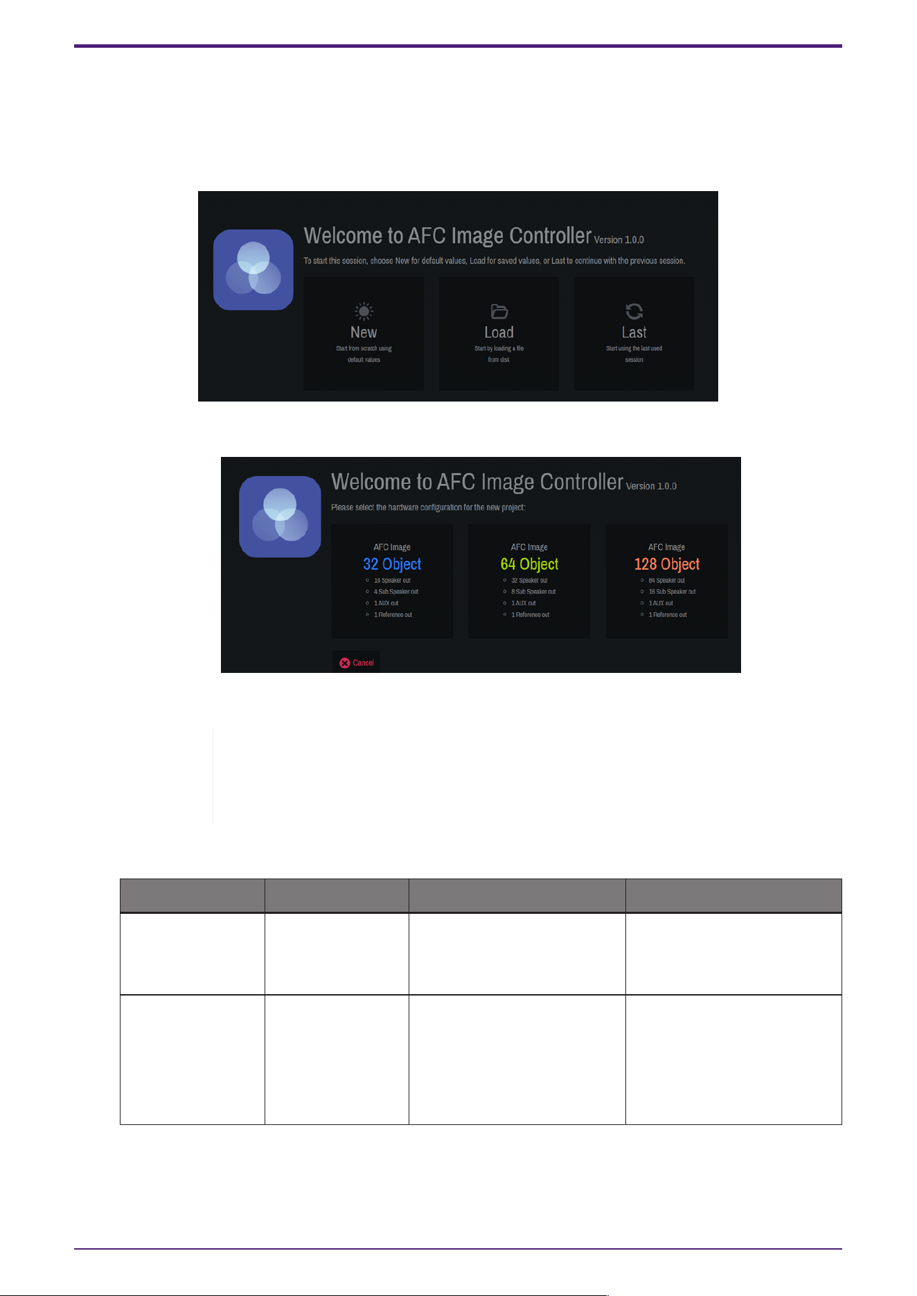
At startup, you can choose to create a new file, open an existing file, or open the previous project file.
• [New]: A new project file will be created.
Select the component according to your license.
The number of required licenses varies depending on the device to be connected.
The DME7 requires the optional expansion kit "DEK-AFC-I" (sold separately). With the
DME10, the inputs can be expanded up to 128 channels and the outputs up to 64
channels by purchasing the additional "NX-AFC-I."
Refer to the table below for the components that can be added depending on the number of licenses.
Hardware 0 licenses 1 license 2 licenses
DME7 Not available 32 in - 16 out × 1
64 in - 32 out × 1
or
32 in - 16 out × 1
DME10 32 in - 16 out
64 in - 32 out × 1
or
32 in - 16 out × 2
128 in - 64 out × 1
or
64 in - 32 out × 2
or
32 in - 16 out × 3
• [Load]: The saved project file ".afciprj" will be read.
• [Last]: The state when the software was closed the last time will be restored.
4. Names and Functions of Respective Parts
9 | AFC Image Controller V1.0 User Guide
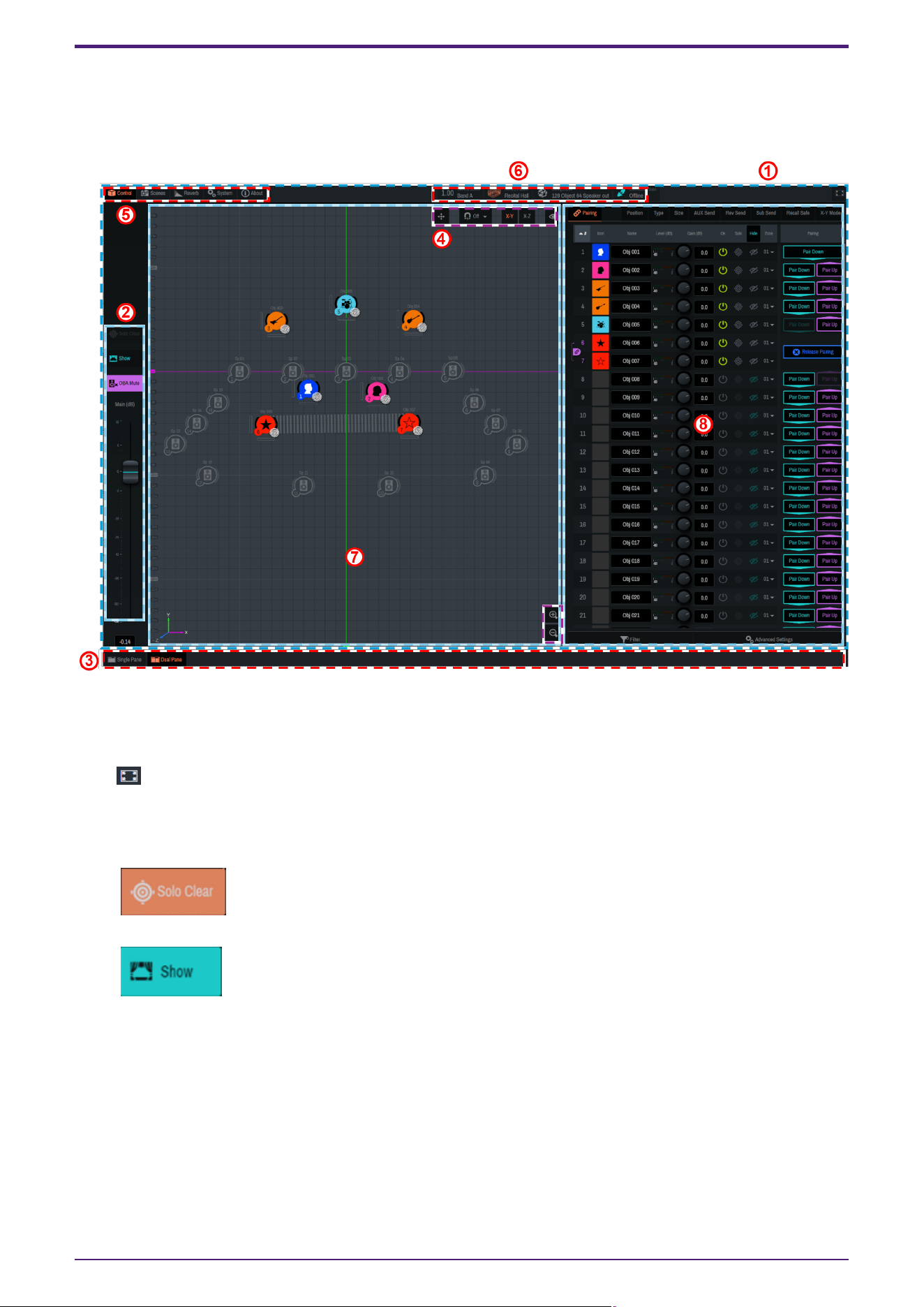
4.2. Common to All Windows
AFC Image Controller consists of the "main window," "window display selector," "function window display area,"
and "status area."
① "Main window"
The "main window" contains the main fader section, 2D Stage window, and Controls window. The display will
differ depending on the display size of the software.
Click " " to view in full screen.
② "Main fader section"
You can control on/off of the Show mode and the main volume.
•
[Solo Clear]
All Solo settings on sound objects and speakers will be cleared.
•
[Show]
This item will be used during real performances of musicals, concerts, or such occasions.
Turning on this item enables the Show mode and restricts the Solo function. In addition, the following
functions are also restricted:
◦
OBA Mute
◦
Zone settings for sound objects
◦
Zone settings for 3D reverb
◦
Import function for Speakers and SubSpeakers
◦
Changing the coordinates of Speakers and SubSpeakers, and on-off switching
4. Names and Functions of Respective Parts
AFC Image Controller V1.0 User Guide | 10
◦
Distance Attenuation and Precision in Advanced Settings
If the same AFC Image component is connected to AFC Image Controllers of
multiple computers, changes to the following items will also be restricted:
▪
Network Interface, Device, Component/Online, and Configuration under
[System] - [Settings]
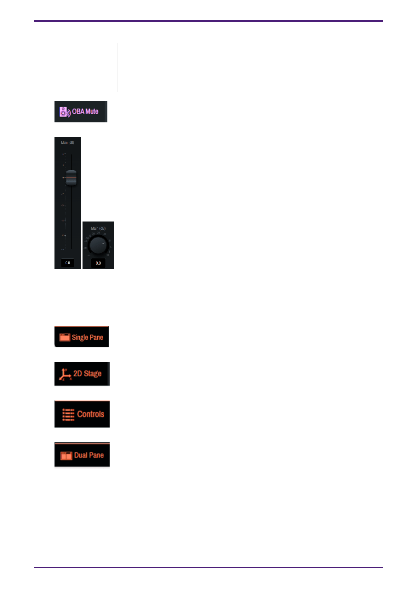
•
[OBA MUTE]
OBA Main will be muted.
•
[Main(dB)]
The OBA Main volume will be adjusted.
The volume graphic changes depending on the window size.
③ "Window display selector"
The content displayed in the main window will be switched.
•
[Single Pane]
The 2D Stage window or Controls window will be maximized.
•
[2D Stage]
Only the 2D Stage window will be displayed in the main window.
•
[Controls]
Only the Controls window will be displayed in the main window.
•
[Dual Pane]
The two-screen view of the 2D Stage window and the Controls window will be displayed.
The 2D Stage window displays the current sound objects and the positions of Speakers and SubSpeakers.
You can also place a sound object, Speaker, or SubSpeaker by dragging it with the mouse.
4. Names and Functions of Respective Parts
11 | AFC Image Controller V1.0 User Guide
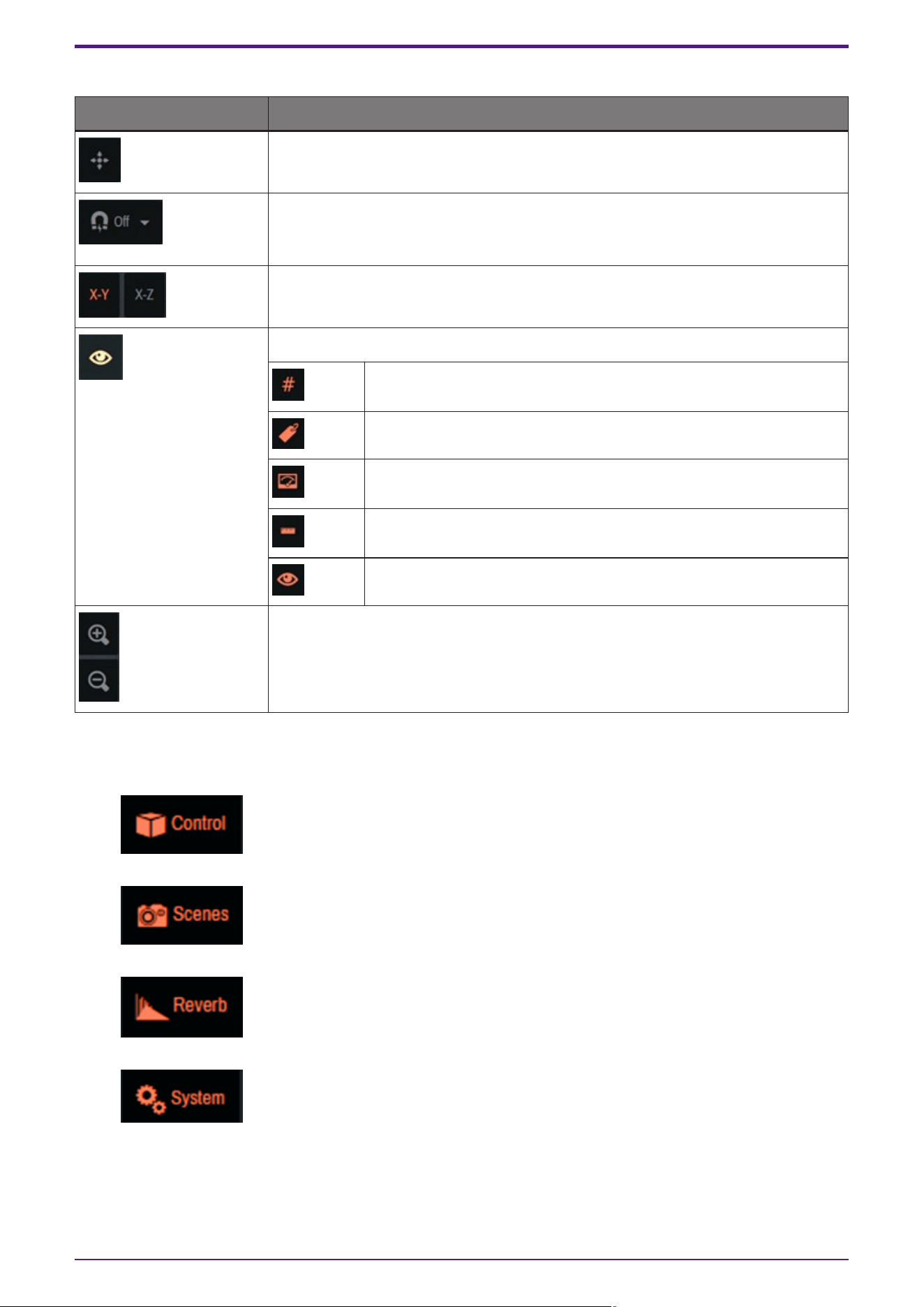
④ "2D Stage operation"
Button Illustration Function
Displays the origin (X, Y, Z = 0).
Sets the interval at which sound objects are moved when dragged in the 2D Stage
window. The movement interval can be selected from 0.1, 0.2, 0.5, and 1.0 (m).
When this button is set to off, the movement interval will be 0.01 m.
Switches the display of the 2D Stage window between X-Y (plan view) and X-Z
(section view).
Switches show/hide on the 2D Stage.
ID number
Name
Level(dB)
Size
Speakers、SubSpeakers
Enlarges or reduces the display area.
⑤ "Function window"
Functions that can be executed by AFC Image Controller are grouped by settings in the function window.
•
[Control]
Set the parameters of sound objects.
•
[Scenes]
Store or recall scenes.
•
[Reverb]
Set 3D reverb and EQ.
•
[System]
Configure system-wide settings, such as output adjustment, connection to a DME7/10, and saving project
files.
4. Names and Functions of Respective Parts
AFC Image Controller V1.0 User Guide | 12
•
[About]
Check the version of AFC Image Controller.
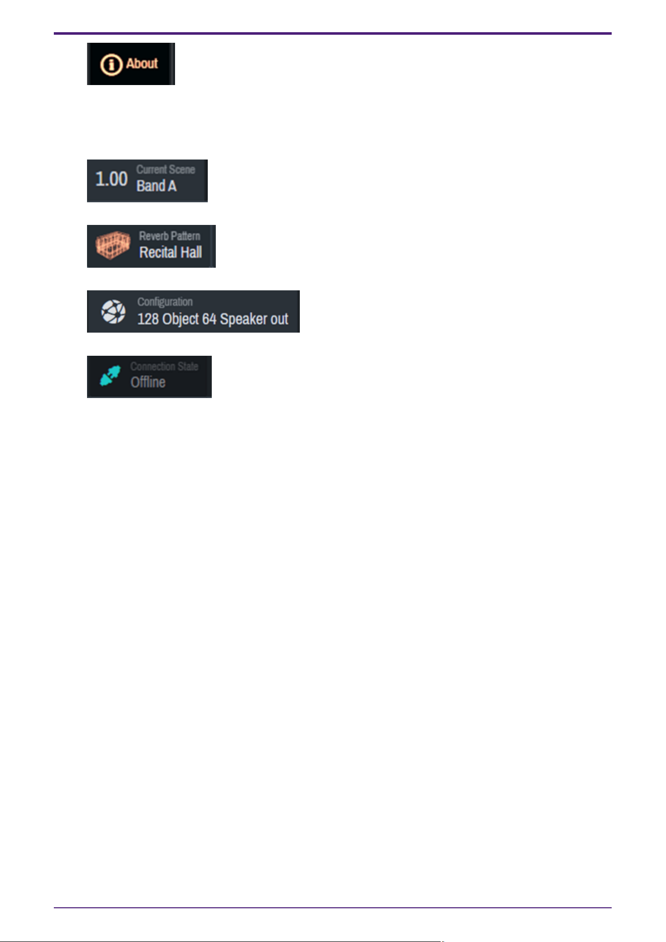
⑥ Status area
The status area displays the current status of each item.
•
[Current Scene] button
The current scene will be displayed. Click this button to move to [Scenes].
•
[Reverb Pattern]
The current reverb pattern will be displayed. Click this button to move to [Reverb].
•
[Configuration]
The current configuration will be displayed. Click this button to move to [System]-[Settings].
•
[Connection State]
The connection status with the device will be displayed. Click this button to move to [System]-[Settings].
⑦ 2D stage window
⑧ Controls window
4. Names and Functions of Respective Parts
13 | AFC Image Controller V1.0 User Guide
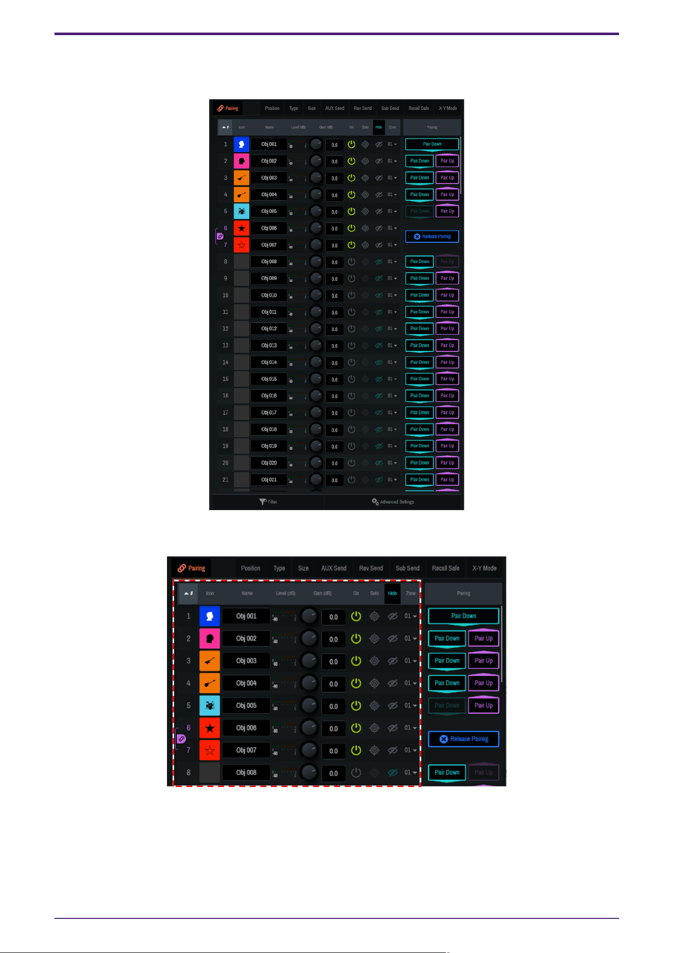
4.3. Controls Window
Set the parameters for each sound object.
4.3.1. Setup of sound objects
4. Names and Functions of Respective Parts
AFC Image Controller V1.0 User Guide | 14
Setting Item Overview
#ID number The ID number of the sound object. Click # at the top to sort by ID number.
Icon Sets the icon and color tone for each sound object.
Name Displays/allows you to edit the name of each sound object. Click Name at the
top to sort by name.
Level(dB) Displays the input level of each sound object.
Gain(dB) Adjusts the gain of each sound object.
On Sets the on/off setting for each sound object.
Solo Sets the Solo on/off setting for each sound object. Click "Solo" at the top to
turn on/off all sound objects at once. The Solo function is restricted in the
Show mode.
Hide Sets the display of sound objects in the 2D Stage window. Click [Hide] at the
top to set the display of all sound objects at once.
Zone Displays the currently assigned zone. Use the down arrow to change the zone.
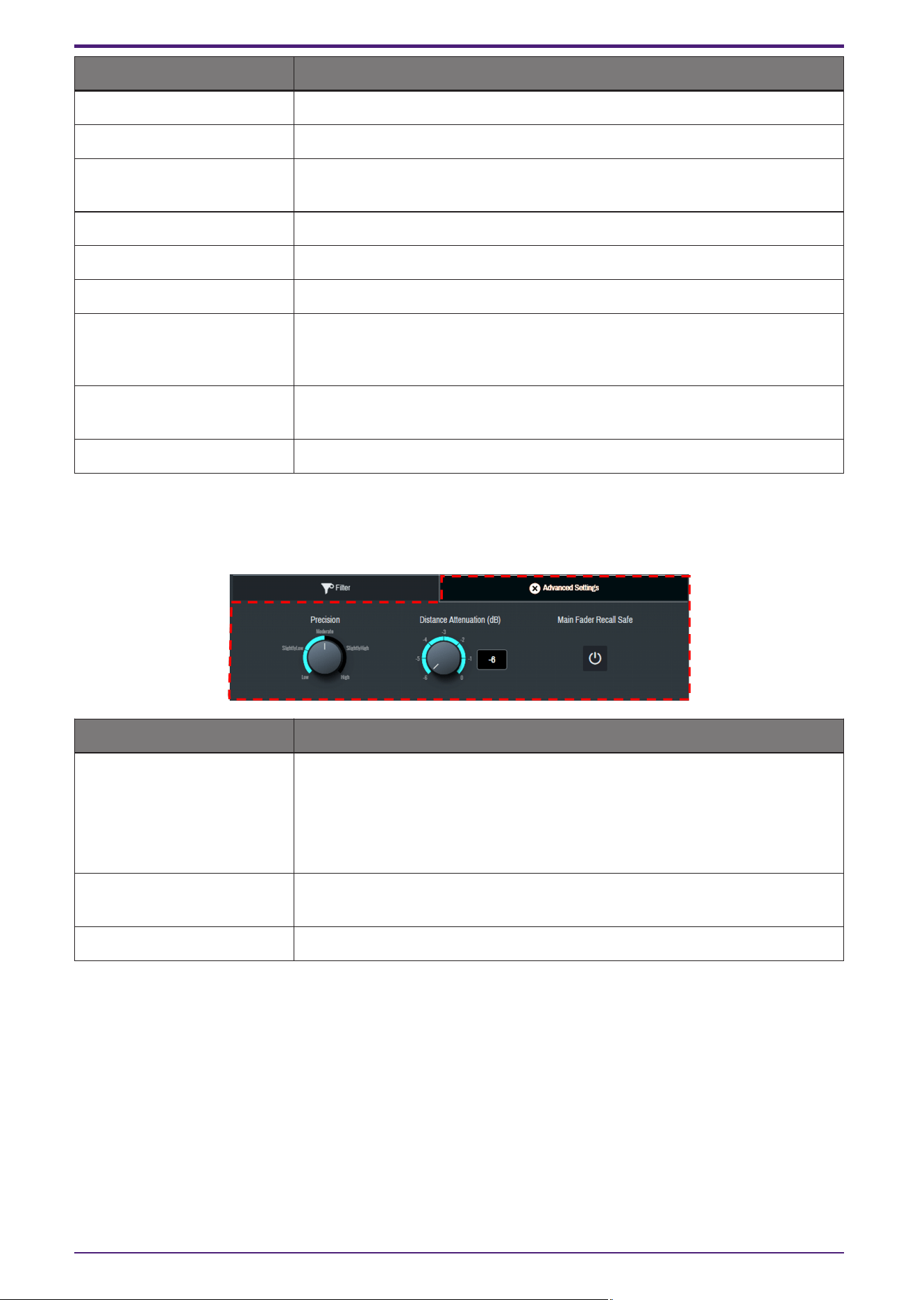
4.3.2. Advanced Settings
Configure the advanced function settings of sound objects. The settings will be reflected in all sound objects.
Function Explanation
Precision
Sets the precision of sound object localization in five levels.
When the precision is set to High, localization will be clearer, but sound object
movements will be less smooth.
When the precision is set to Low, the sound object movements will be
smoother, but the localization will be unclear.
Distance Attenuation(dB) Sets the distance attenuation when a sound object is localized outside the
speakers. The attenuation can be set from -6 to 0 dB.
Main Fader Recall Safe Applies Recall Safe to [Main(dB)].
4. Names and Functions of Respective Parts
15 | AFC Image Controller V1.0 User Guide
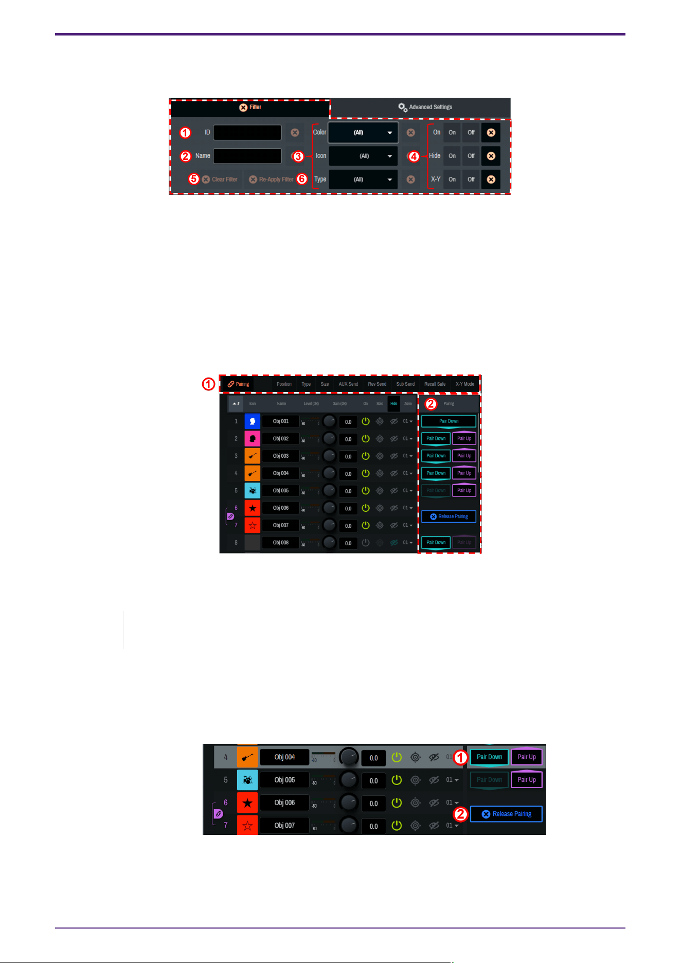
4.3.3. Filter
Narrow down the sound objects to be displayed. Multiple narrowing conditions can be selected.
① The sound objects to be displayed are narrowed down to those meeting the condition entered in ID number.
② The sound objects to be displayed are narrowed down to those meeting the condition entered in Name.
③ The sound objects to be displayed are narrowed down to those meeting the conditions selected in Color, Icon,
and Type.
④ The sound objects to be displayed are narrowed down based on On, Hide, and on/off of X-Y Mode.
⑤ All narrowing conditions are reset.
⑥ The previously selected narrowing conditions are displayed again.
4.3.4. Sound object parameter settings
① When a parameter name is clicked, the selected function will be displayed to the right of the sound object list
(② in the image).
Depending on the Single Panel view or the software screen size, items other than the selected
item may be displayed in the Controls window.
•
[Pairing]
The following parameters can be paired between two sound objects whose ID numbers are adjacent to
each other.
◦
Gain, Solo, Hide, Position, Size, AUX Send, Rev Send, Recall Safe, Settings
① [Pair Down] [Pair Up]
Adjacent sound objects will be paired.
4. Names and Functions of Respective Parts
AFC Image Controller V1.0 User Guide | 16
② [Release Pairing]
The pairing will be canceled.
•
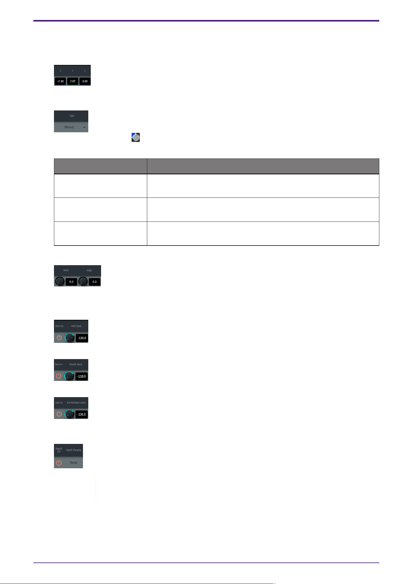
[Position]
The position of the sound object will be displayed/set in X, Y, and Z coordinates. Set the
coordinates between -500 (m) and 500 (m).
•
[Type]
Select the method for controlling the coordinates of the sound object.
When a fingerprint mark " " is displayed for the sound object in the 2D Stage window, the object can be
directly moved within the 2D Stage window.
Setting Explanation
Manual Allows for controlling the position of the sound object from AFC Image
Controller or an external controller.
Static Disables controlling the position of the sound object from AFC Image
Controller or an external controller.
External Allows for controlling the position of the sound object only from an
external controller.
•
[Size]
Set the width in the X-Y plane and the height in the Z axis direction of the sound object
between 0.0 and 100.0. When the values are set to 100.0, audio will be output from all speakers in the
zone to which the sound object is assigned.
•
[AUX Send]
Set on/off and the send level of the AUX send.
•
[Rev Send]
Set on/off and the send level of the reverb send. Audio after gain adjustment will be sent.
•
[Sub Send]
Set on/off and the send level of Sub Send. Audio of the selected sound object will be sent to
[SubSpeakers] in [System]. Audio after gain adjustment will be sent.
•
[Recall Safe]
Recall Safe is a function that protects scene memories from being recalled. The Recall
Safe settings are saved separately from scene data.
Set on/off of the Recall Safe function. When the function is set to on, the parameter settings of sound
objects will be retained when a scene is recalled. When the function is set to off, the scene will be recalled
regardless of the parameter settings of the sound objects.
In addition, [Rec/S Params] allows you to set Recall Safe in detail for each item.
4. Names and Functions of Respective Parts
17 | AFC Image Controller V1.0 User Guide
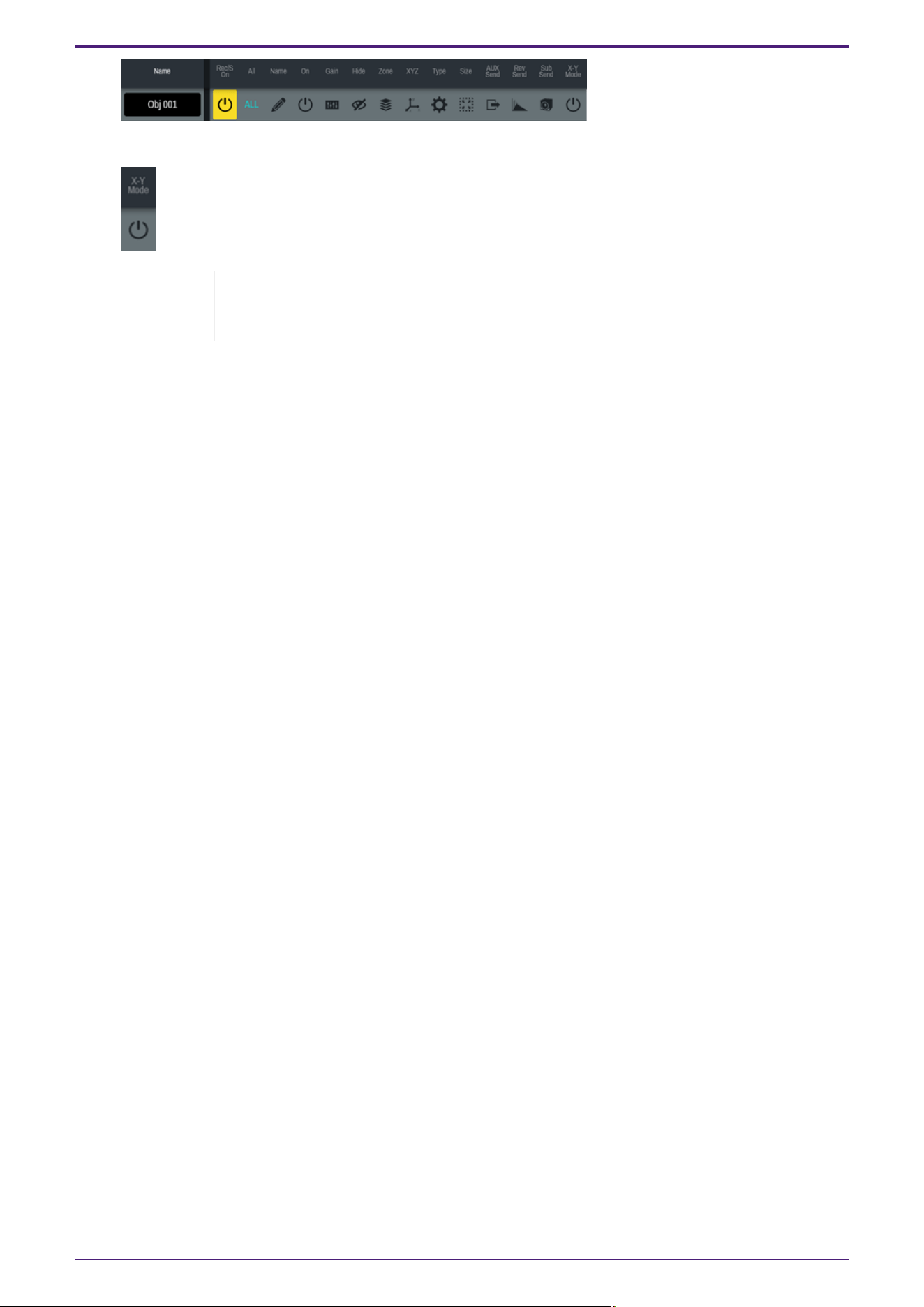
•
[X-Y Mode]
Set the X-Y mode.
When the X-Y mode is set to on, the Z coordinate value of the sound object will be
ignored, and rendering will be performed regardless of the Z coordinate of each
speaker.
4. Names and Functions of Respective Parts
AFC Image Controller V1.0 User Guide | 18
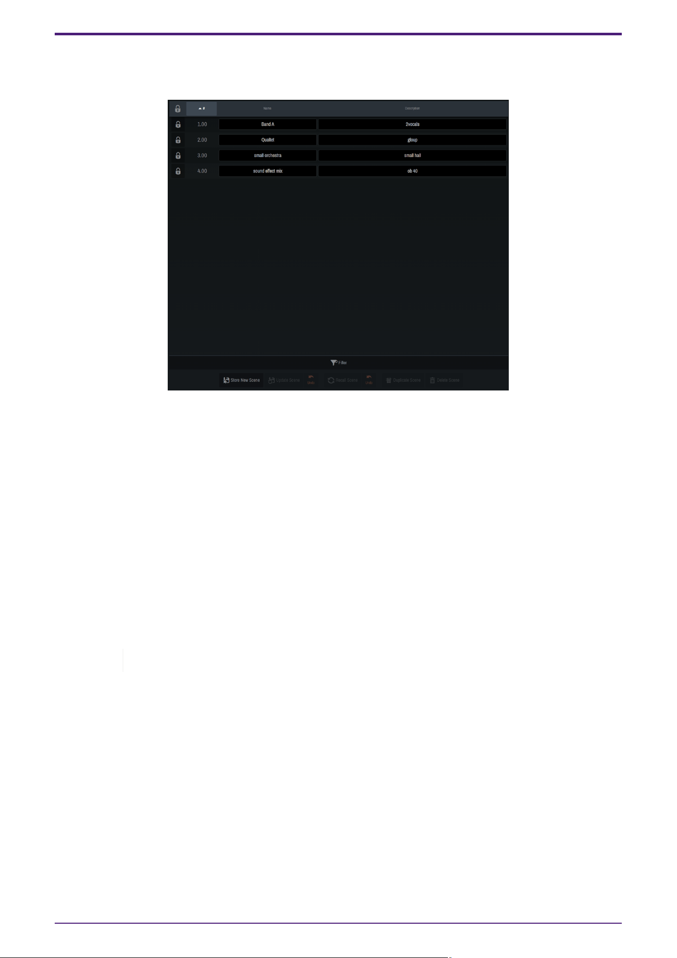
4.4. Scenes Window
You can name the current settings and save them as a "scene." Saved scenes can be recalled at any time.
The following information can be saved in a scene:
• On/off and gain settings of sound objects
• Display, position, size, icon, color, name, and type of sound objects
• Level setting of Main (dB)
• On/off and level setting of AUX Send
• On/off and level setting of Rev Send
• On/off and level setting of Sub Send
• On/off setting of X-Y Mode
• On/off setting of Hide
• Zone settings
• Reverb (Time, Space, and Equalizer) settings
The [Pairing] setting is not included in the scenes.
4. Names and Functions of Respective Parts
19 | AFC Image Controller V1.0 User Guide
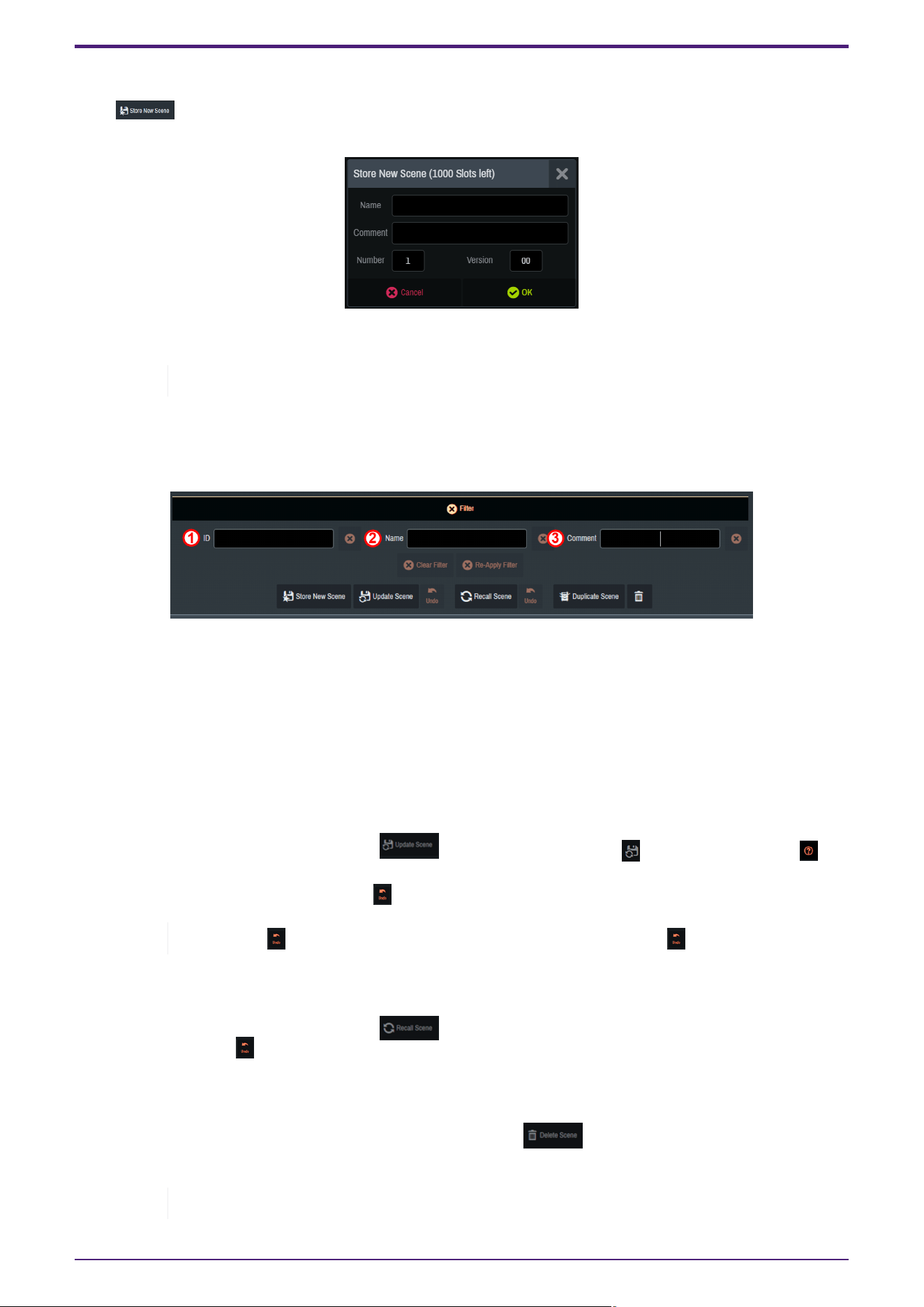
4.4.1. Registering a scene
Click [ ] to open the dialog screen.
When registering a scene, you can enter the following information:
• Name (Scene name) / Comment (Annotation) / Number (1 to 1000) / Version (0 to 99)
Up to 1000 scenes can be registered.
Once you have entered the information, click [OK] to register the scene. The registered scene will be reflected in
the list. The Name and Comment (Annotation) of a registered scene can be edited from the Scene list. You can
also narrow down the scenes displayed in the Scene list using [Filter].
Multiple narrowing conditions can be selected.
① The scenes to be displayed are narrowed down to those meeting the condition entered in ID number.
② The scenes to be displayed are narrowed down to those meeting the condition entered in Name.
③ The scenes to be displayed are narrowed down to those meeting the condition entered in Comment.
4.4.2. Overwriting a scene
Overwrite an already registered scene with the current parameters.
Select the scene to be overwritten and click [ Update Scene]. When the [ ] mark has changed to [ ],
click the button again to overwrite the scene.
To cancel the overwrite, click the activated [ Undo] button.
If you click [ Undo] by mistake, you can cancel the Undo by clicking [ Undo] again.
4.4.3. Recalling a scene
Select a scene from the Scene list and click [ Recall Scene]. To cancel recalling the scene and return to
the original state, click [ Undo].
4.4.4. Deleting a scene
Select the scene to be deleted from the Scene list, and then click [ Delete Scene]. When the [Delete
Scene] button turns orange, click it again to delete the scene.
Once a scene is deleted, it cannot be restored.
4. Names and Functions of Respective Parts
AFC Image Controller V1.0 User Guide | 20
4.4.5. Duplicating a scene
Select the scene you want to duplicate and click [ Duplicate Scene].
A dialog appears with only the Version value of the original scene updated. You can rewrite the information as
desired and duplicate the scene.
Note that if you enter a Number or Version value that already exists, the existing scene will be
overwritten.
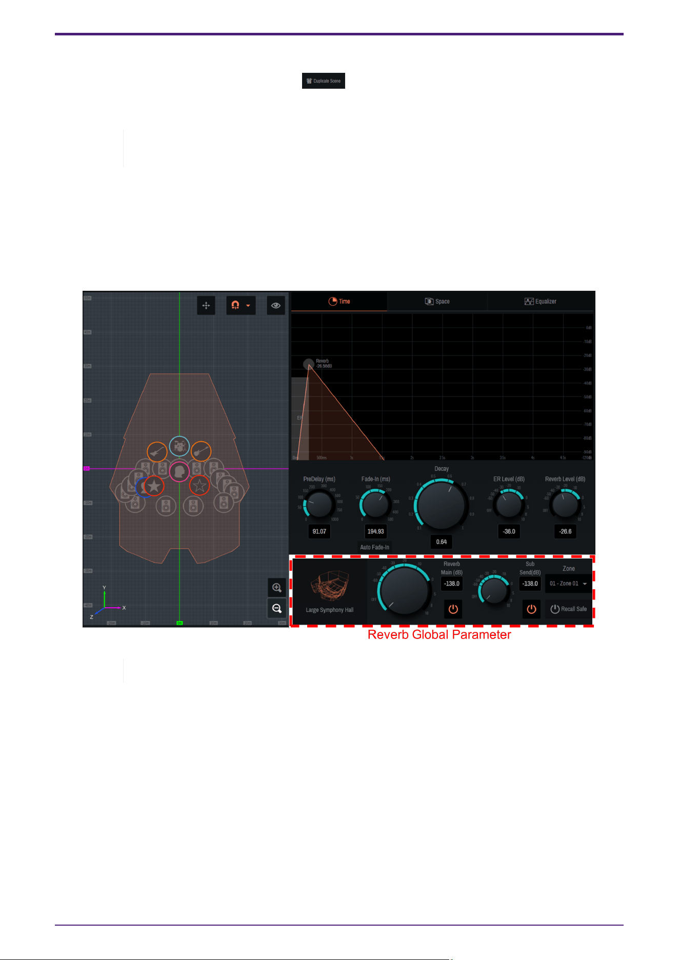
4.5. Reverb Window
You can create the optimal reverberation based on the position of each sound object, and generate a reverb
effect signals optimized for the position of each speaker.
This window offers multiple presets with different spatial shapes, and allows you to intuitively operate the
temporal, spatial, and frequency parameters of the reverb components.
Only one reverb pattern can be selected at a time.
4. Names and Functions of Respective Parts
21 | AFC Image Controller V1.0 User Guide
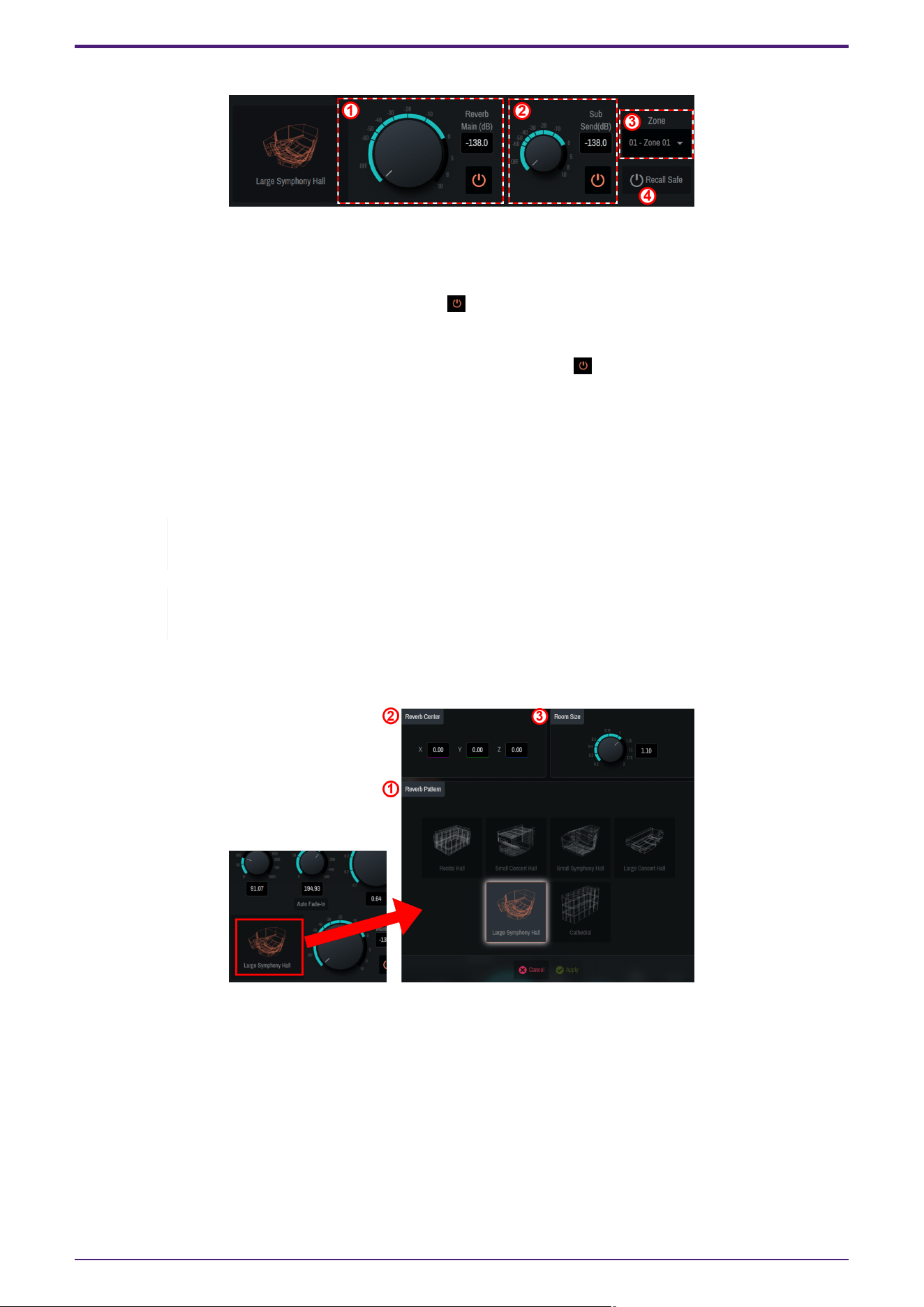
4.5.1. Reverb Global Parameter
Adjust the overall output level of the reverb and determine the output zone.
① [Reverb Main (dB)]
Adjust the overall output level of the reverb. Also, use " " to switch on/off.
② [Sub Send]
Adjust the level of the reverb to be output to the SubSpeakers. Also, use " " to switch on/off.
③ [Zone]
Select the zone from which the reverb will be output.
④ [Recall Safe]
Set on/off of the Recall Safe function. If this item is on, no memory is recalled.
Recall Safe is a function that protects scene memories from being recalled. The Recall Safe
settings are saved separately from scene data.
To apply an edited reverb pattern to a different zone, we recommend using a scene. For the
scene settings, refer to section 4.4.
4.5.2. Reverb pattern selection
① Click the room icon, select a reverb pattern from six types, and adjust it. After selecting a pattern, set the
following parameters.
② [Reverb Center]
Set the center coordinates of the selected reverb pattern. Enter the coordinates directly, or drag the orange label
in the 2D Stage window.
③ [Room Size]
Set the size (magnification) of the room for the selected pattern.
4. Names and Functions of Respective Parts
AFC Image Controller V1.0 User Guide | 22
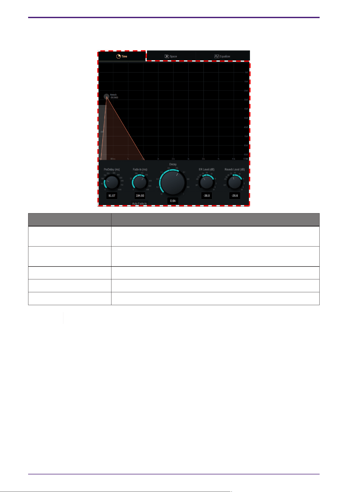
4.5.3. Time screen
The [Time] window allows you to set the temporal parameters of the reverbs.
Setting Explanation
Pre-Delay(ms) Adjusts the delay time before the reverb, including early reflections, takes
effect.
Fade In (ms) Adjusts Fade-in Time of the reverb. Turn on [Auto Fade-in] to adjust it
automatically.
Decay Adjusts the decay time of the reverb.
ER Level(dB) Adjusts the early reflection level.
Reverb Level(dB) Adjusts the reverb level.
You can also intuitively operate the displayed graph by dragging it.
4. Names and Functions of Respective Parts
23 | AFC Image Controller V1.0 User Guide
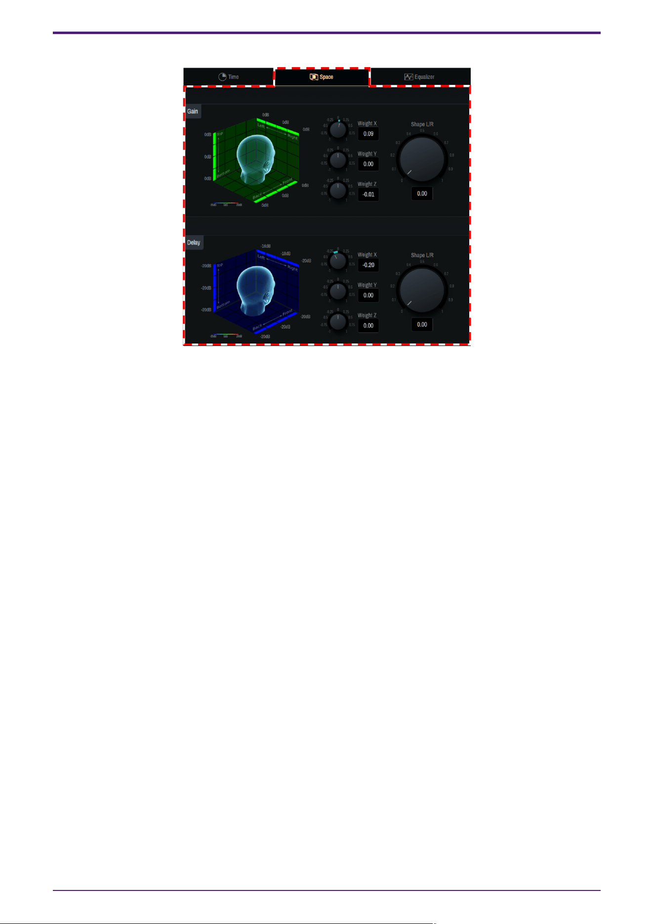
4.5.4. Space screen
The [Space] window allows you to adjust the spatial characteristics of the 3D reverbs. The head image helps to
intuitively understand the spatial changes of parameters centered around the human head facing in the positive
Y-axis direction.
[Gain]
Adjust the gain bias for each axis of weight X, Y, and Z. In addition, the gain distribution in the center and sides in
the X-axis direction can be adjusted using the Shape L/R knobs.
[Delay]
Adjust the delay bias for each axis of weight X, Y, and Z. In addition, the delay distribution in the center and sides
in the X-axis direction can be adjusted using the Shape L/R knobs.
4. Names and Functions of Respective Parts
AFC Image Controller V1.0 User Guide | 24
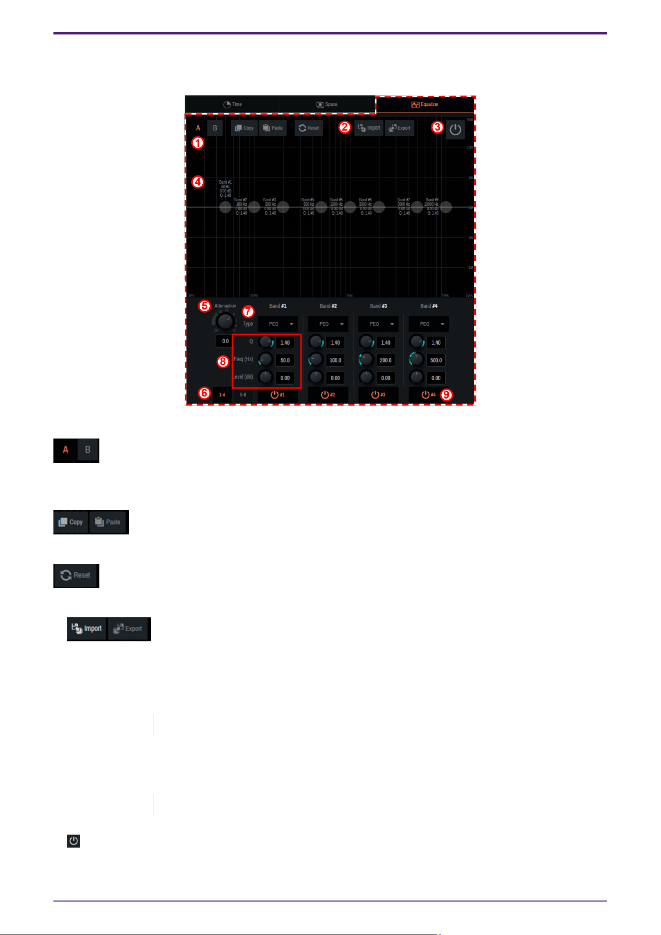
4.5.5. Equalizer screen
The [Equalizer] window allows you to adjust the frequency characteristics of the reverb using an eight-band EQ.
①
[A] [B]
You can create two types of EQ, bank A and bank B.
The types can be switched freely, which allows you to compare them.
[Copy] [Paste]
Copy and paste the created EQ.
[Reset]
Reset the EQ of the selected bank.
② [Import] [Export]
The set EQ can be read/saved as a file.
a.
When reading saved data
Click [Import], select the file to read in the pop-up window that appears, and click [Open].
If the file cannot be read, the message "Failed to open the file" will be displayed.
b.
When saving the set data
Click [Export], enter a file name in the pop-up window that appears, and click [Save].
If the file cannot be saved, the message "Failed to save the file" will be displayed.
③ [Power Button]
This button switches on/off of EQ.
4. Names and Functions of Respective Parts
25 | AFC Image Controller V1.0 User Guide

④ EQ graph
The EQ for the currently selected bank will be displayed. You can also manipulate each band directly on the
graph.
⑤ [Attenuation]
Adjust the attenuator.
⑥ [1-4] [5-8]
EQ bands will be switched.
⑦ [Type]
Select the EQ type from the ▼ button. The color of the frequency characteristic curve and part of the graph outer
frame changes depending on the type.
⑧ [Q] [Freq(Hz)] [Level(dB)]
Set the parameters of the EQ selected in ⑦.
⑨ [ Power button image]
On/off will be switched only for the EQ of the selected band.
4. Names and Functions of Respective Parts
AFC Image Controller V1.0 User Guide | 26
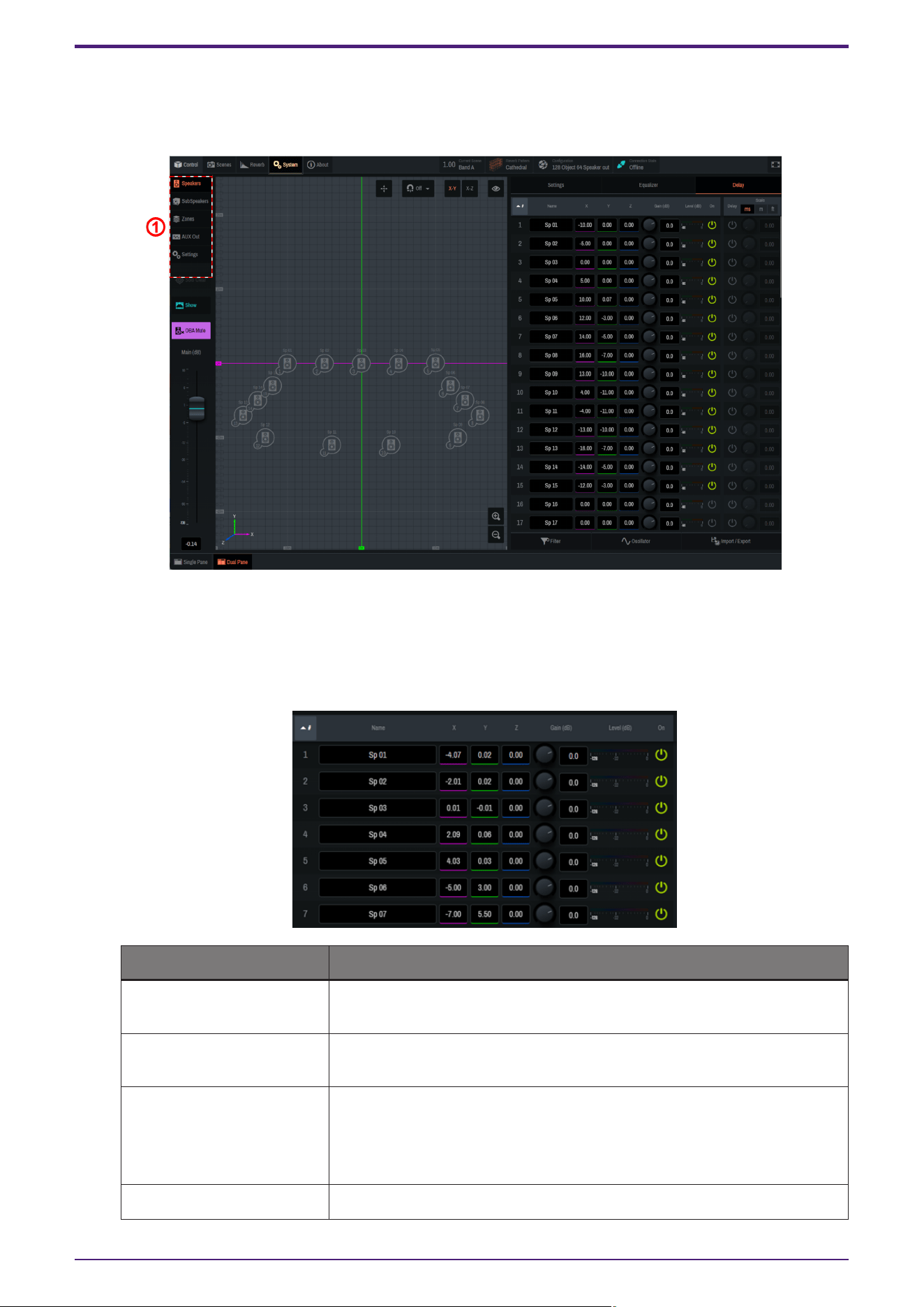
4.6. System Window
Configure the output settings, such as Speakers, SubSpeakers, Zone, and AUX Out, as well as the settings for
connections with external devices.
① Use the tabs to switch functions. When a tab is selected, each function will be displayed in the main window.
4.6.1. Speakers/SubSpeakers tab
• Speakers/SubSpeakers parameter settings
Setting Item (Settings) Overview
#ID number The ID number of each Speaker/SubSpeaker. Click # at the top to sort by
ID number.
Name Displays/allows you to edit the name of each Speaker/SubSpeaker. Click
Name at the top to sort by name.
X, Y, Z Displays/sets the position [m] of each Speaker/SubSpeaker. You can
directly move the Speaker/SubSpeaker icons on the 2D Stage window.
Once the position is determined, click [✓ Apply] at the top of the window
to confirm the change. To cancel the change, click [× Cancel].
Gain(dB)
Adjusts the level of each Speaker/SubSpeaker.
4. Names and Functions of Respective Parts
27 | AFC Image Controller V1.0 User Guide
Setting Item (Settings) Overview
Level(dB)
Displays the output level of each Speaker/SubSpeaker.
On Sets on/off of each Speaker/SubSpeaker.
OSC Outputs the noise set in [Oscillator].
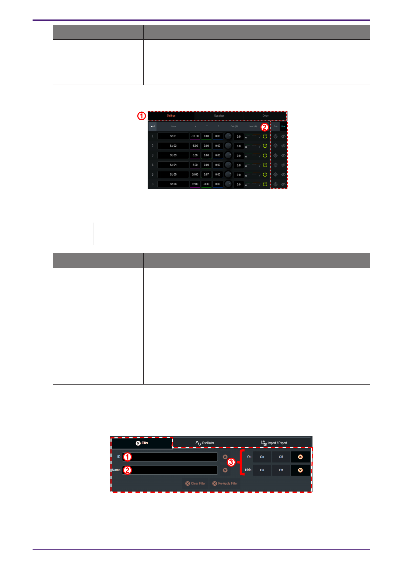
• Speaker/SubSpeaker parameter switching
① When a parameter is clicked, the selected function will be displayed to the right of the speaker list (②
in the image).
Depending on the Single Panel view or the software screen size, items other than the
selected item may be displayed in the Controls window.
Setting Item (Settings) Overview
Settings Solo: The Solo on/off will be set for each Speaker/SubSpeaker. Click [Solo]
at the top to turn all Speakers/SubSpeakers on/off at once. The Solo
function is restricted in the Show mode.
Hide: The display of Speakers/SubSpeakers in the 2D Stage window will
be set. Click [Hide] at the top to set the display of all
Speakers/SubSpeakers at once.
Equalizer Sets EQ for each Speaker/SubSpeaker. To learn how to set EQ, refer to
"4.5.5 Equalizer screen."
Delay Sets the delay for each Speaker/SubSpeaker. The delay scale can be
selected from three types.
• Other settings
[Filter]
Narrow down the list items by ID number or Name. Multiple narrowing conditions can be selected.
① The Speakers/SubSpeakers to be displayed are narrowed down to those meeting the condition entered
in ID number.
② The Speakers/SubSpeakers to be displayed are narrowed down to those meeting the condition entered
4. Names and Functions of Respective Parts
AFC Image Controller V1.0 User Guide | 28
in Name.
③ The Speakers/SubSpeakers to be displayed are narrowed down based on On and on/off of Hide.
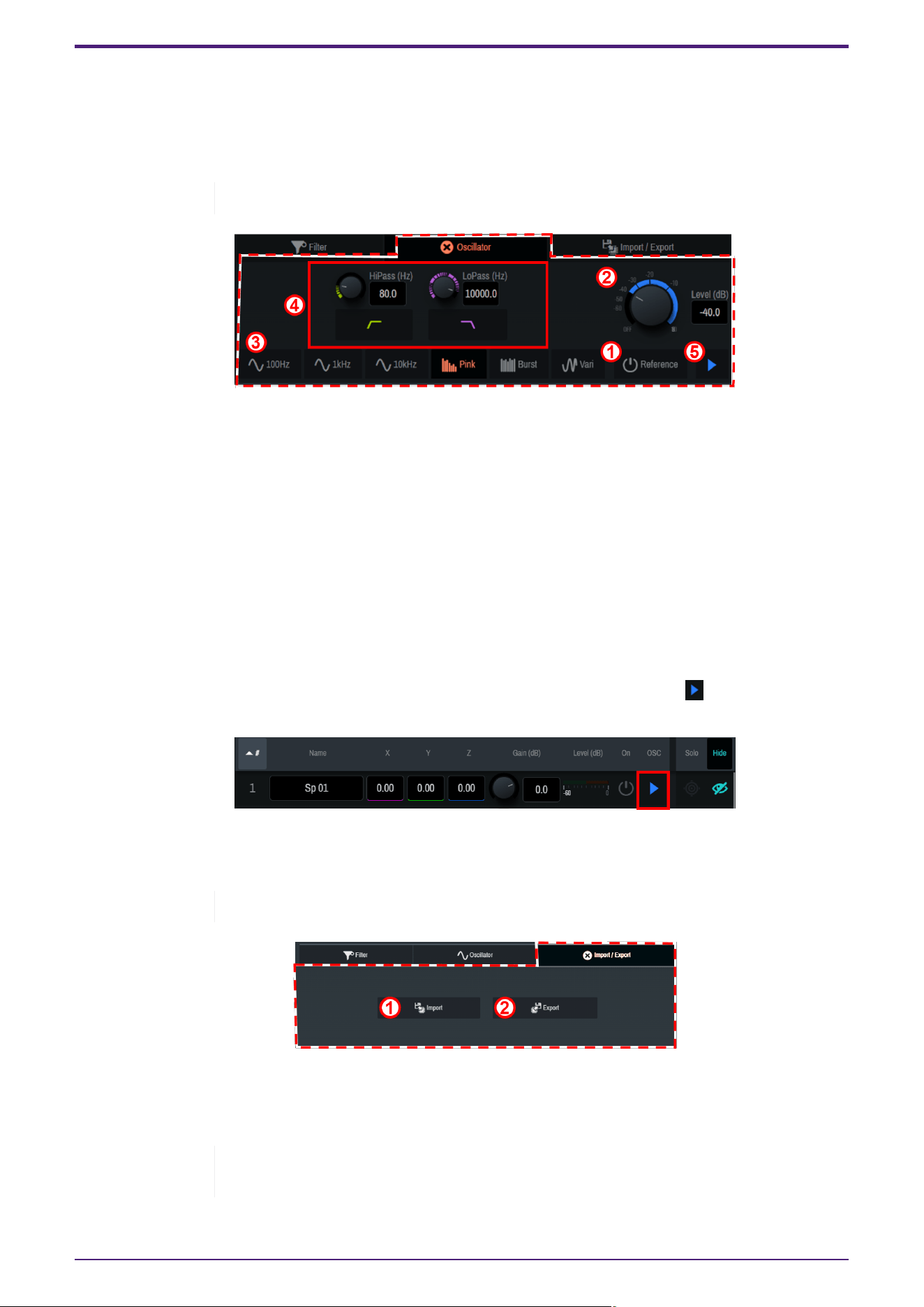
[Oscillator]
This item allows you to select, edit, and output a sine wave or pink noise.
The same setting is also applicable from Oscillator of AUX Out.
① [Reference]
When this item is turned on, the oscillator signals will be output to Oscillator Reference Out.
② [Level(dB)] knob
Set the output level.
③ Oscillator mode selection
Select the mode from six types of waveforms.
④ [Advanced settings window]
You can configure detailed settings when Pink, Burst, or Vari is selected.
⑤ [Play button]
When this button in turned on, the oscillator signal output goes on standby. Press [ Play button] for
each Speaker to output the signals.
[Import/Export]
Import or export speaker data.
SubSpeakers do not have the import and export functions.
① Import: Speaker position data in a ".nys" file will be imported.
② Export: Speaker position information will be exported as a.nys file.
The .nys file created with the NEXO NS-1 software can be imported into AFC Image
Controller.
4. Names and Functions of Respective Parts
29 | AFC Image Controller V1.0 User Guide
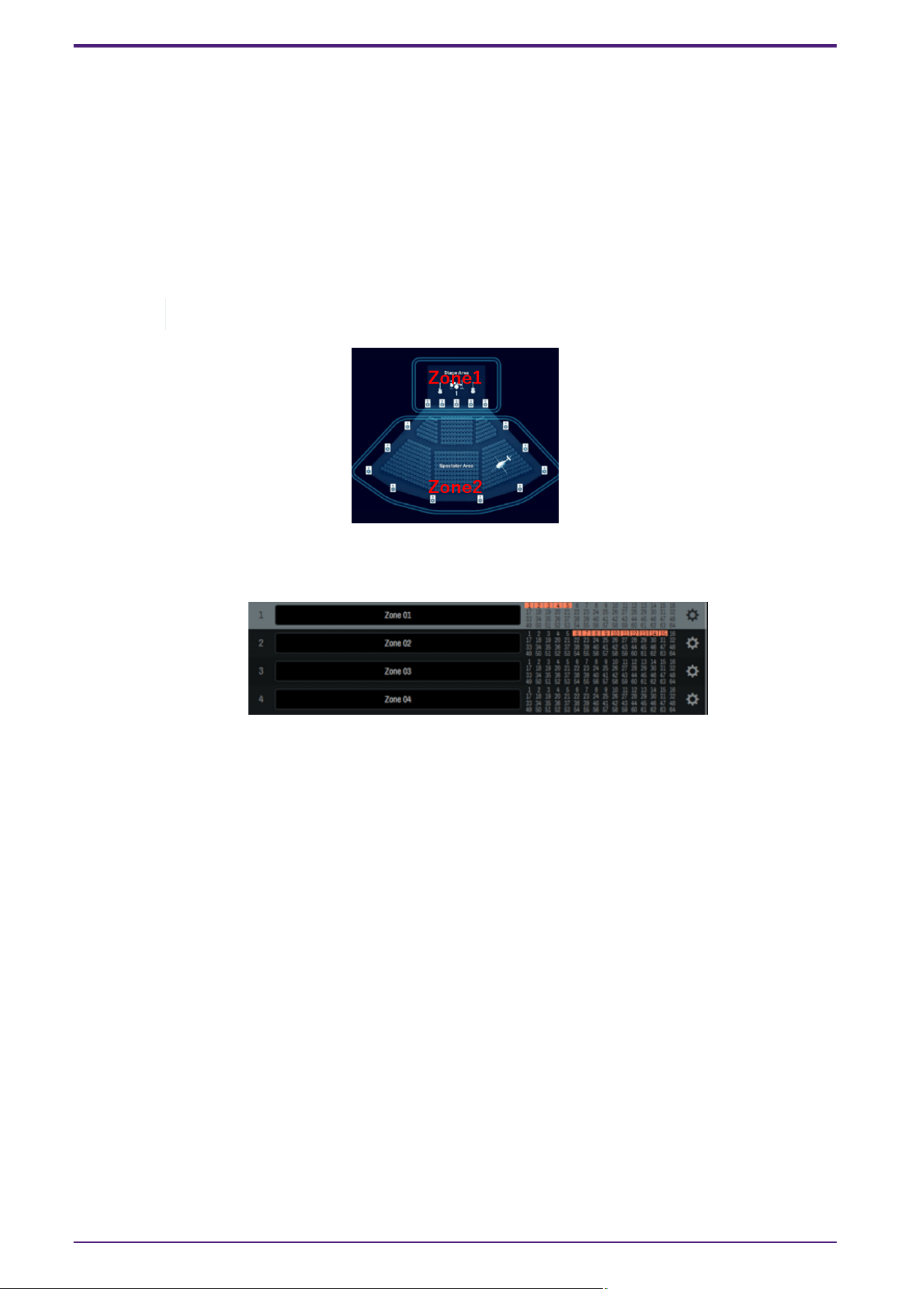
4.6.2. Zones tab
"Speaker zoning" is a function to assign the playback of a sound object only to a specific speaker group. You can
create up to 32 speaker zones and assign multiple speakers to each speaker zone.
Each sound object is output only from the speakers in its assigned zone. Therefore, the range of sound object
control is not limited even if speaker systems with different roles are mixed in the same space.
For example, zoning is possible in the way that sound objects on the stage are output only from the front
speakers, and sound objects that move the sound image on the audience seat side are output only from the wall
and ceiling speakers on the audience seat side.
Each speaker zone can also be set with a rendering area that converts panning in logical coordinates, such as
those from an external DAW or mixing console, into any shape in real space.
The RIVAGE series V7.0 and later support control.
•
Assigning speakers to a zone
Click to select the speakers to be assigned to a zone. You can also edit the name of the zone.
4. Names and Functions of Respective Parts
AFC Image Controller V1.0 User Guide | 30
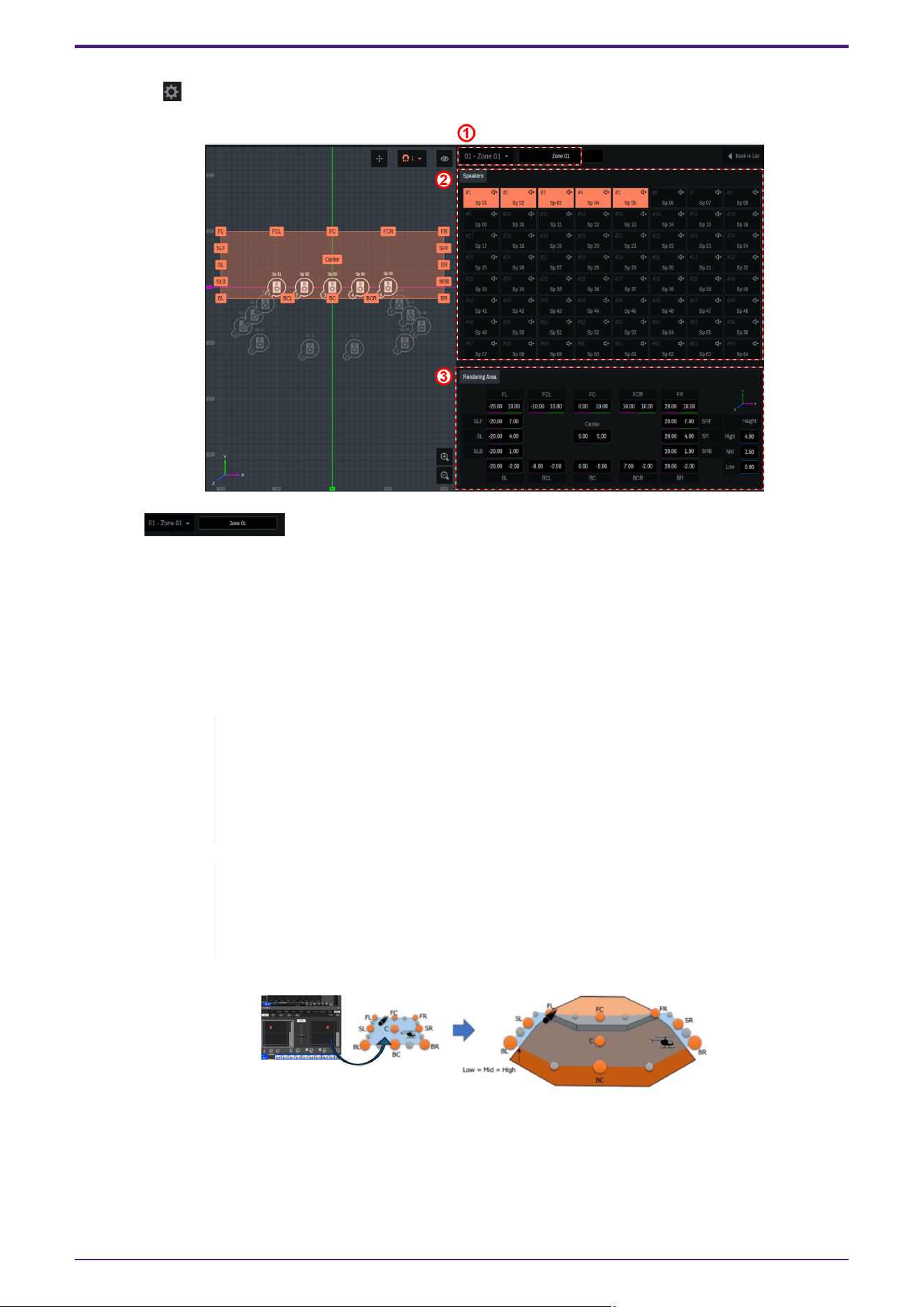
•
Zone settings
Click " " to configure detailed zone settings.
① [ ]
Select a zone and edit the name of the zone.
② [Speakers]
Select the speakers to assign to the zone.
③ [Rendering Area]
Move the label icon on the 2D Stage or enter a numerical value to set the rendering area. For the Z-axis
direction, enter the value in the Height field.
◦
Assign three or more speakers to the zone to be used for rendering.
◦
Do not place all the speakers in a zone in a straight line.
◦
If the X, Y, or Z coordinate of a sound object is controlled from AFC Image
Controller or an external controller, the coordinate will not be converted into the
rendering area.
About rendering areas
The rendering area settings are applied to the cases where the position information of
sound objects is controlled with logical coordinates such as those of external DAW, the
panner of a mixing console, or ADM-OSC.
4. Names and Functions of Respective Parts
31 | AFC Image Controller V1.0 User Guide
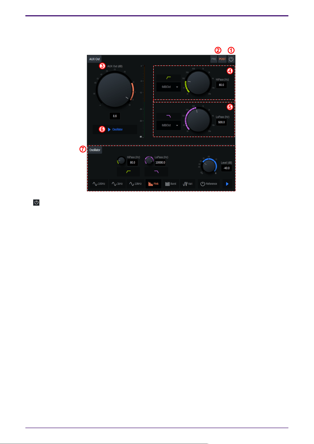
4.6.3. AUX Out tab
Configure the AUX Out settings.
① [ Power button]
This button allows you to turn on/off the AUX Out output.
② [PRE] [POST] switch buttons
These buttons allow you to switch sending of signals to the AUX bus of a sound object between PRE and POST.
③ [AUX Out(dB)]
Adjust the output level of AUX Out.
④ [HiPass]
Set the high-pass filter. The filter type can be selected from the ▼ button.
⑤ [LoPass]
Set the low-pass filter. The filter type can be selected from the ▼ button.
⑥ [▶ Oscillator]
The specified oscillator signals will be sent to AUX Out.
⑦ [Oscillator]
This item allows you to select, edit, and output a sine wave or pink noise. For operation instructions, refer to
4.6.1. Speakers/SubSpeakers tab.
4. Names and Functions of Respective Parts
AFC Image Controller V1.0 User Guide | 32
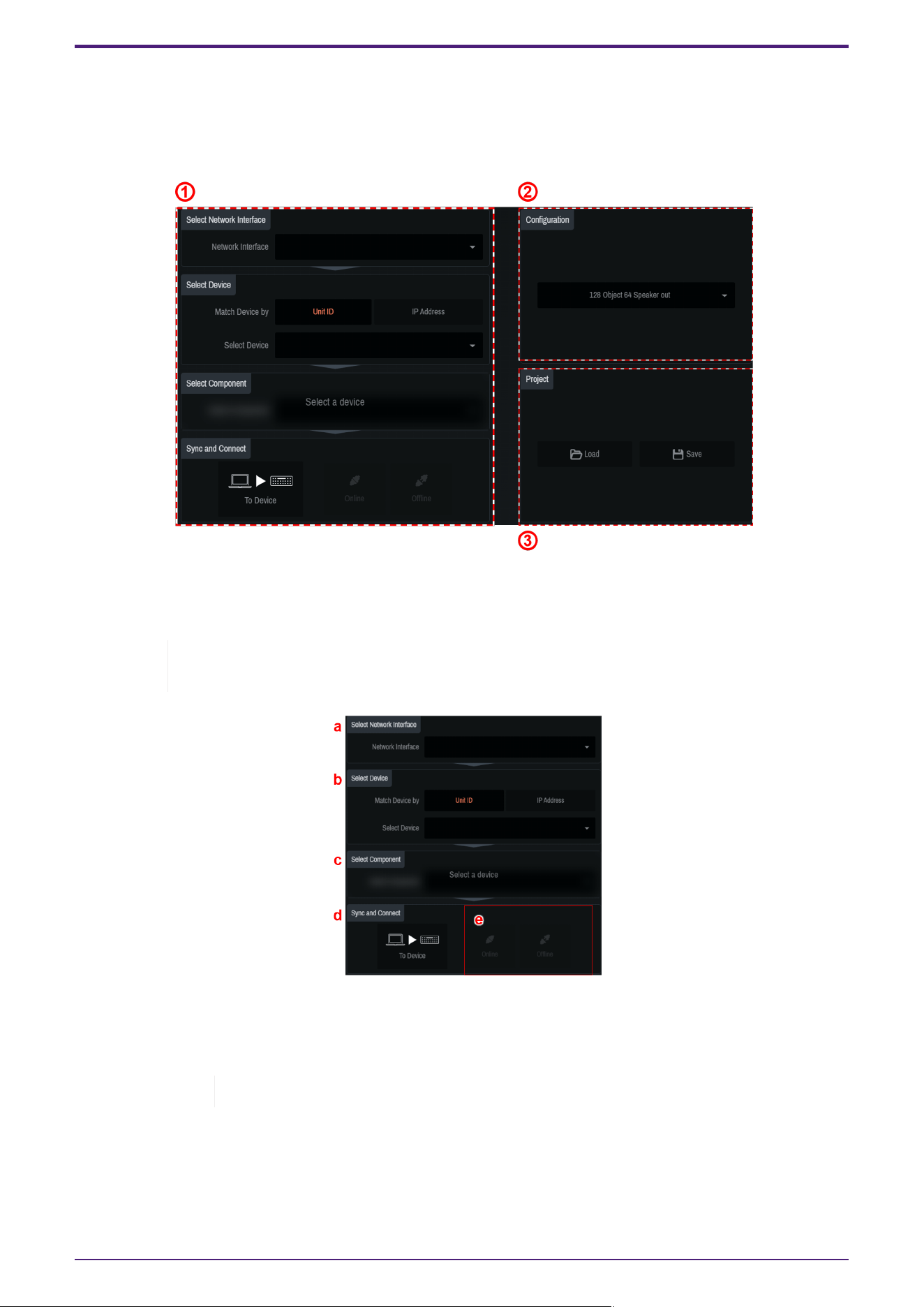
4.6.4. Settings tab
Save project files you have created and set synchronization between the DME and the computer.
For the DME, you need to set a configuration in which AFC Image components are placed beforehand using
ProVisionaire Design. To learn how to set the configuration, refer to 3. Basic Usage.
① "Sync" area
Connect the DME and computer and synchronize them for using AFC Image Controller to control the DME.
The state in which the DME and AFC Image Controller operate in synchronization is called the
"online state." Also, the operation to achieve this state is called "synchronization."
a.
[Select Network Interface]
Select the network interface to be used by the computer from the list. Set the IP addresses of the network
interface and DME to be used so that they are on the same network.
For the DME network settings, refer to the DME7/DME10 Reference Manual.
b.
[Select Device]
Select the DME to be connected. To search for DMEs on the same network, select Unit ID or IP Address
from [Match Device by].
◦
For Unit ID: Select the DME to be connected from the list.
4. Names and Functions of Respective Parts
33 | AFC Image Controller V1.0 User Guide
◦
For IP Address: Enter the IP Address and press the Find button. Information about the found device
will be displayed. If the device is not found, the error message "Unable to find device at [entered IP
Address]" will be displayed.
The indicator shows the synchronization status with the DME.
Green: Offline state
White: Lost state
The lost state means that the device you want to connect to cannot be found due to factors such
as the device being turned off.
Blue: Online state.
Yellow: Incompatible state
c.
[Select Component]
Select the component ID of the AFC Image component set in ProVisionaire Design.
If there are multiple AFC Image components, select the target component.
d.
[Sync and Connect]
Select the method for synchronizing the DME and AFC Image Controller.
To Device: The AFC Image Controller settings will be sent to the DME and will overwrite its settings.
From Device: The DME settings will be read into AFC Image Controller.
When connecting from multiple computers at the same time, you can select To Device
only for the computer that is first connected and synchronized with the DME.
For the second or subsequent computers, only "From Device" can be selected.
e.
Select Online. (If the conditions are not met, the button will not be displayed.)
If a PIN code is specified when the AFC Image components are placed using ProVisionaire Design, enter
the specified PIN code in the window that appears.
If the incorrect PIN code is entered, the message "Component Access PIN is incorrect."is displayed.
To learn how to set the PIN code, refer to 2.1.1.
② "Configuration" area
Select the configuration of the DME to be connected.
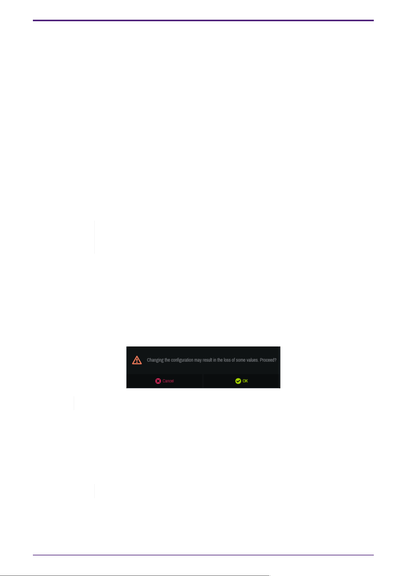
When changing the configuration, you may lose parameter settings.
③ "Project" area
Save or read the created projects.
•
[Load]
Double-click the saved.afciprj file to launch this software and load the project file.
In the dialog that appears after the click operation, select the file to read.
If the file cannot be read, the message "Failed to open the file" will be displayed.
•
[Save]
Save the current state as a project file.
In the dialog that appears after the click operation, name the current settings and save them.
4. Names and Functions of Respective Parts
AFC Image Controller V1.0 User Guide | 34

If the file cannot be saved, the message "Failed to save the file" will be displayed.
4.7. About Window
You can check the current version information and various license information.
4. Names and Functions of Respective Parts
35 | AFC Image Controller V1.0 User Guide
5. Snapshot Integration with DME
5.1. SnapShot Linking Procedure
You can register a scene created with the AFC Image Controller to a Provisionare Design snapshot and recall it
at the same time.
AFC Image components cannot be registered in a Parameter Set.
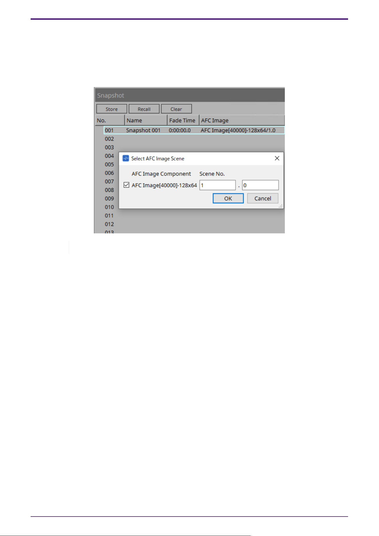
Register a snapshot from Store of Snapshot.
Double-click the AFC Image column of the registered snapshot.
In the dialog that appears, register any AFC Image component and scene number.
When you click Recall, if a scene with the specified number is registered in the AFC Image, that scene will be
recalled.
If the scene with the specified number is not registered in the AFC Image, nothing will be recalled for the AFC
Image.
5. Snapshot Integration with DME
AFC Image Controller V1.0 User Guide | 36
5.2. How to Change Number of In/Out of Placed AFC Image Component
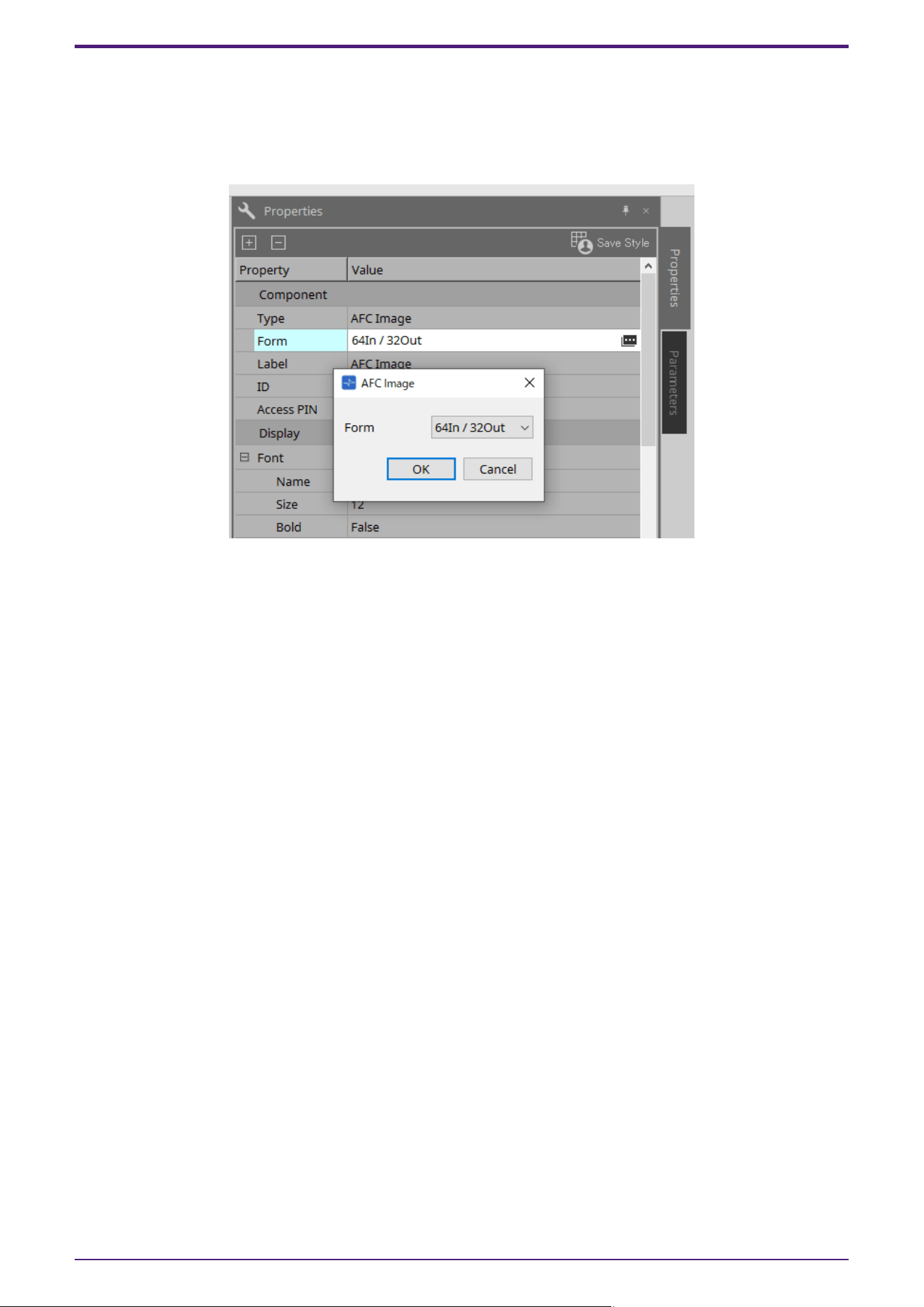
Click on a placed AFC Image component.
From Property on the right side of the screen, click the Value column of Component > Form.
In the AFC Image dialog of Form, change the number of inputs and outputs to the desired number.
5. Snapshot Integration with DME
37 | AFC Image Controller V1.0 User Guide

© 2025 Yamaha Corporation
Published 06/2025
HS-A0
