
MILWAUKEE TOOL
l
www.milwaukeetool.com
13135 W. Lisbon Road, Brookeld, Wisc. 53005
Drwg. 6
34
29 30
31 33
28
18
19
20
21
22
23
24
25
26
27
30
29
31
33
39
35
38
46
50
42
40
47
41
32
43
36
37
44
45
51
49
36 37 38
39 41
14
56
10
15
6
9
8
7
5
4
3
2
1.3
1.2
1.1
13
11
59
1
1.1 1.2
1.3
12
56
17
14 18 19 20 21 22 23
24 25 26 27 28 31 32
53
54
55
48
35 44 45
53 58
*
60
2 6 7 8
9 10 11
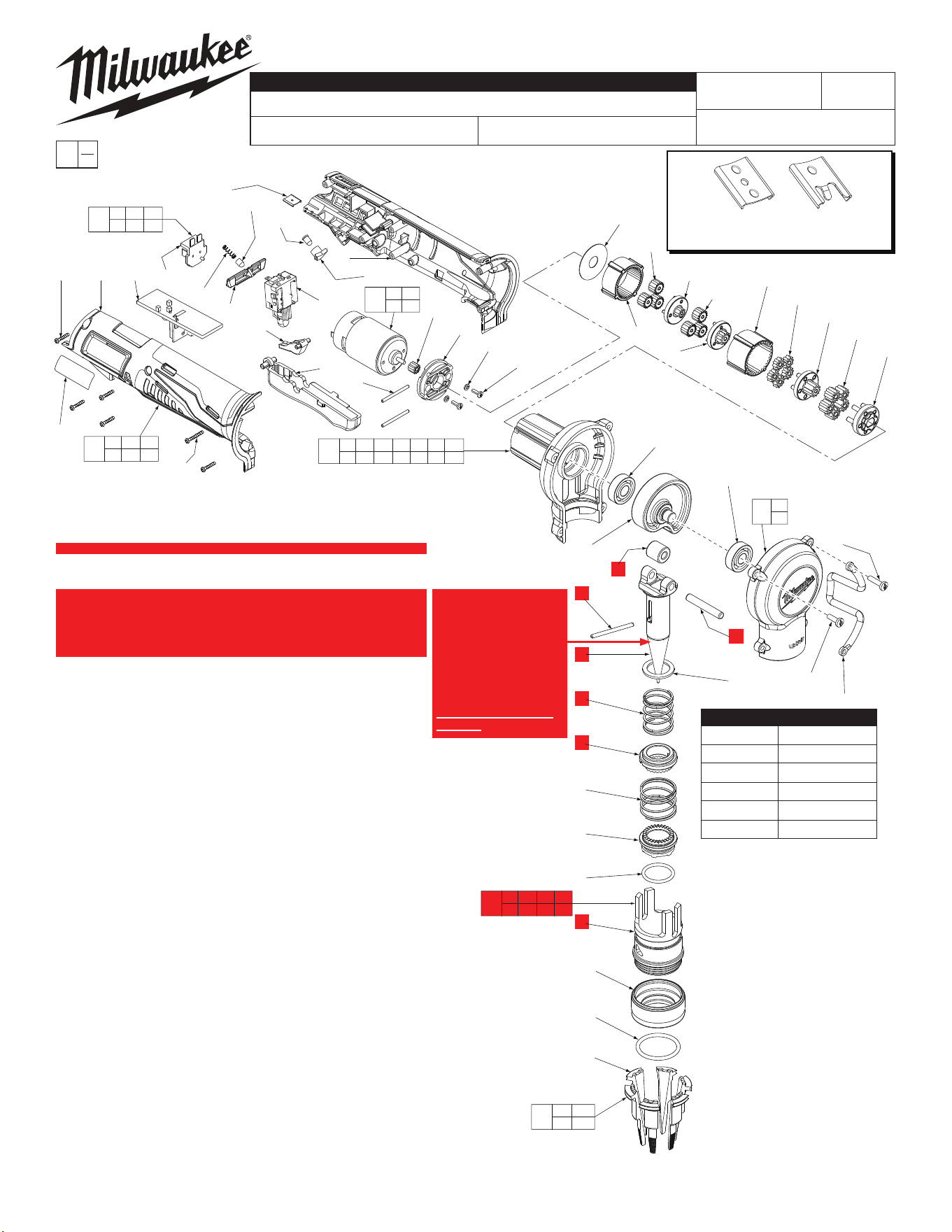
BULLETIN NO.
54-47-0200
SERVICE PARTS LIST
CATALOG NO. 2432-20
REVISED BULLETIN
SPECIFY CATALOG NO. AND SERIAL NO. WHEN ORDERING PARTS
M12™ PEX Expander
STARTING
SERIAL NO.
DATE
June 2022
WIRING INSTRUCTION
C62A
EXAMPLE:
Component Parts (Small #) Are Included
When Ordering The Assembly (Large #).
0
00
SEE PAGE 4
52
PART NO. SIZE
49-16-2403 3/8" Head Assy.
49-16-2404 1/2" Head Assy.
49-16-2405 5/8" Head Assy.
49-16-2406 3/4" Head Assy.
49-16-2408 1" Head Assy.
FIG. 1 (Head Assortment)
To remove an Expander Head,
unscrew from tool in a counter-
clockwise direction.
Be sure Expander Head is free of
any dirt and debris.
Use a clean, lint-free cloth to apply
a thin coat of Milwaukee Expand-
er Cone Grease, No. 49-08-2400
to the cone of the Spindle (9). Do
not over-lubricate.
See page 3 for additional
lubrication notes.
Reinstall Expander Head onto
tool in a clockwise direction. Hand
tighten securely. Do not over
tighten. The Expander Head must
t snuggly against the shoulder of
the tool.
The Gearcase Assembly (17) comes with a
Motor Mount Bracket (31) that must be
removed and discarded when servicing. A
Motor Mount Bracket already exists
on the Motor Assembly (34).
42-70-0058
Improved
Design
Original
Design
42-70-0055
*
M12™ tools utilize two different Housing
Connection Clip designs depending on the
Handle Set. See page two for details.
FIG. PART NO. DESCRIPTION OF PART NO. REQ.
1 See Chart Head Assembly (Optional, see chart) (1)
1.1 --------------- Segment (6)
1.2 --------------- Garter (1)
1.3 --------------- Ring (1)
2 --------------- Frame (1)
3 34-40-1050 O-Ring (1)
4 42-76-0950 Rotating Collar (1)
5 40-50-1575 Collar Spring (1)
6 --------------- Pin (1)
7 --------------- Drive Collar (1)
8 --------------- Return Spring (1)
9 --------------- Spindle (1)
10 --------------- Roller (1)
11 --------------- Roller Pin (1)
12 28-20-1390 Gearcase Cover Assembly (1)
13 06-82-5320 8-32 x 5/8" Pan Hd. Slt. Tapt. T-20 Scr. (2)
14 02-04-1005 Ball Bearing (1)
15 36-10-0680 Cam and Shaft Assembly (1)
17 28-14-2330 Gearcase Assembly (1)
18 --------------- 4th Carrier (1)
19 --------------- 4th Planet Gear (5)
20 --------------- 4th Sun Gear (1)
21 --------------- 3rd Planet Gear (5)
22 --------------- 3rd and 4th Ring Gear (1)
23 --------------- 3rd Sun Gear (1)
24 --------------- 2nd Planet Gear (3)
25 --------------- 2nd Sun Gear (1)
26 --------------- 1st Planet Gear (3)
27 --------------- 1st and 2nd Ring Gear (1)
28 --------------- Washer (1)
29 45-88-1980 Spring Washer (2)
30 05-81-0205 M3 x 6 Pan Hd. Motor Screw (2)
31 42-36-0840 Motor Mount Bracket (1)
32 44-60-1530 Motor Mount Pin (2)
33 --------------- Motor Pinion (1)
34 23-30-0625 Motor Assembly (1)
35 --------------- Handle Halve - Left (1)
36 --------------- PCBA (1)
37 --------------- Connector Block (1)
38 --------------- LED (1)
39 --------------- LED Holder (1)
40 31-76-0325 Shuttle (1)
41 --------------- Switch (1)
42 44-10-0825 Trigger Lever (1)
43 31-92-0570 Trigger (1)
44 --------------- Handle Halve - Right (1)
45 06-82-1080 M3 x 14 Pan Hd. Plast. T-10 Screw (5)
46 43-72-0430 Shuttle Detent (1)
47 40-50-1475 Shuttle Detent Spring (1)
48 31-44-2475 Handle Kit (1)
49 23-66-2840 Switch Assembly (1)
50 42-70-0055 Housing Connection Clip (1)
51 12-20-2432 Service Nameplate (1)
52 42-55-2400 Carrying Case, Optional (1)
53 05-88-0675 M3 x 20 Pan Hd. Plast. T-10 Screw (1)
54 06-82-5316 8-32 x 1/2" Pan Hd. Slt. Tapt. T-20 Scr. (2)
55 43-74-0730 Belt Hook (1)
56 02-04-1022 Ball Bearing (1)
57 10-20-2002 Warning Label (Not Shown) (1)
58 --------------- Fuel Gauge Label (Not Shown) (1)
59 45-88-1485 Flat Washer (1)
60 14-46-0419 Spindle and Frame Service Kit (1)
NOTE:
If any of the indi-
vidual components
(2,6,7,8,9,10,11) need
replacing, Service Kit
60 must be ordered,
14-46-0419. Use all
new components
from the kit.
DISCARD ALL OLD
PARTS.
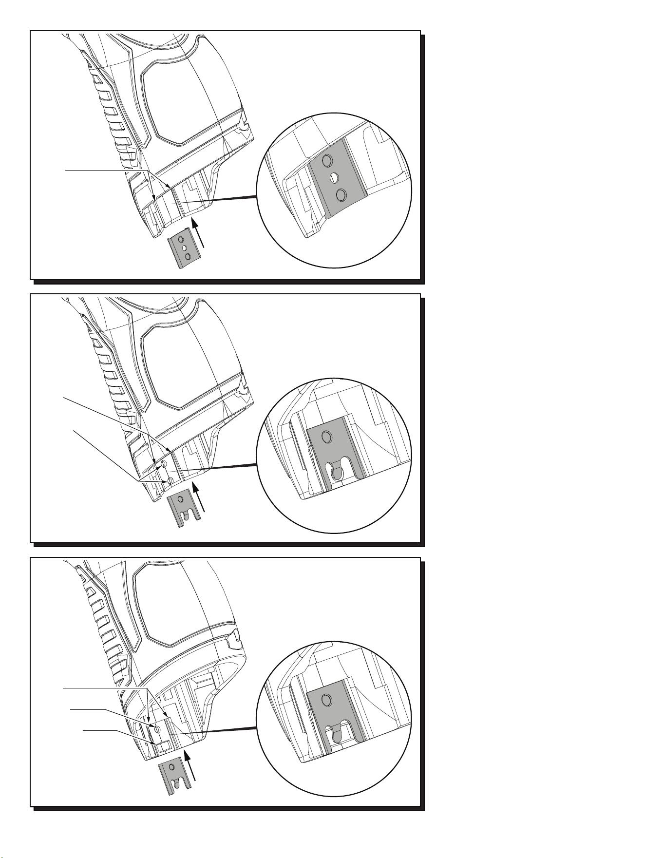
42-70-0055
42-70-0058
42-70-0058
Recess in early handle
sets may only have the
slots to accommodate a
housing clip. Use 42-70-0055
only in this situation.
Slots
Recess in newer handle
sets have two slots, a
dimple and a tab cavity to
accommodate the newer
housing clip design.
Slots
Dimple
Tab Cavity
Updated M12™ Handle Sets utilize Housing
Connection Clips No. 42-70-0055 and 42-70-
0058. (The 42-70-0058 is a preferred upgrade).
Install this clip design by aligning the side rails
of the clip with the two slots in the handle set.
Gently push into place with the aid of a small
flat blade screwdriver or a similar instrument.
Be sure that the clip is properly seated in both
slots and that the tab of the clip snaps down in
the round dimpled cavity of the handle set. Be
sure that the clip is flush to sub-flush to the end
of the handle set. To remove the clip, use the
same small flat blade screwdriver or a similar
instrument and lift up on the clip tab while
pushing the clip out of the handle set. Use a
needle nose pliers to gently rebend the clip tab
if necessary. If the tab on the clip is damaged
during this process and is loose or will not stay
in place, replace with a new 42-70-0058 clip.
Early M12™ Handle Sets utilize Housing
Connection Clip No. 42-70-0055. Install this
clip design by aligning the side rails of the clip
with the two slots in the handle set. Gently
push into place with the aid of a small flat
blade screwdriver or a similar instrument. Be
sure that the clip is properly seated in both
slots and that the clip is flush to sub-flush to
the end of the handle set. To remove the clip,
use the same small flat blade screwdriver or a
similar instrument and push the clip out of the
handle set. If the clip is loose or will not stay in
place, a needle nose pliers can be used to
gently bend/pinch the side rails of the clip. If
the clip is damaged do not use, replace with a
new 42-70-0055 housing clip.
Slots
Dimples
Recess in this
handle set design
has slots and dimples
to secure a housing clip.
The 42-70-0055 can be
used but the 42-70-0058 is
preferred in this situation.
Newer M12™ Handle Sets utilize Housing
Connection Clip No. 42-70-0058. Install this
clip design by aligning the side rails of the clip
with the two slots in the handle set. Gently
push into place with the aid of a small flat blade
screwdriver or a similar instrument. Be sure
that the clip is properly seated in both slots and
that the tab of the clip snaps down in the
rectangular cavity of the handle set. Be sure
that the clip is flush to sub-flush to the end of
the handle set. To remove the clip, use the
same small flat blade screwdriver or a similar
instrument and lift the clip tab out of the cavity
while pushing the clip out of the handle set.
Use a needle nose pliers to gently rebend the
clip tab if necessary. If the tab on the clip is
damaged during this process and is loose or
will not stay in place, replace with a new
42-70-0058 clip.
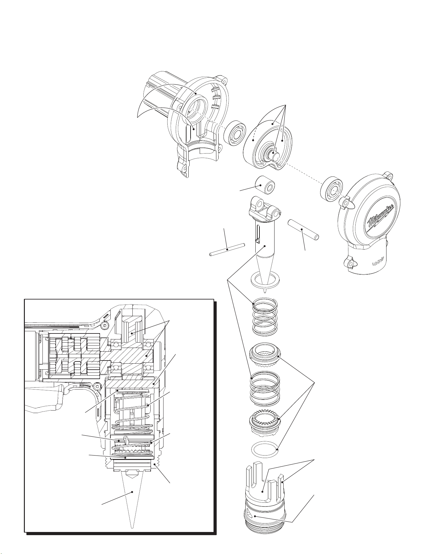
LUBRICATION NOTES:
Use Type 'L' Grease, No. 49-08-4175
Total amount approx. 12 grams (.4 ounces)
When servicing, remove 90-95% of the existing grease prior to installing Type ‘L’.
Original grease maybe similar in color but not compatible with ‘L’.
Place 6 grams (.2 ounces) of grease
in this area of Gearcase Assembly
behind the Cam and Shaft Assembly.
Apply grease to both ends of Cam Shaft
and lightly coat the entire exterior of Cam.
Approx. 2 grams of grease
Lightly coat
Roller Pin
with grease.
Lightly coat
Pin with grease.
Place grease on the entire surface
of the Rotating Collar and Drive
Collar, being sure to apply heavier
amounts on the teeth. Lightly coat
the O-Ring before installing on the
Rotating Collar. Approx. 1.8 grams.
Coat with grease both sides of the
legs of the Frame. Coat the interior
of the Frame proir to installing the
Rotating Collar, Drive Collar,
Springs and O-Ring.
Lightly grease the exterior surface
of the Frame with the two triangle
features.
Apply a light coating of grease to the cylinderical
portion (not the cone) of the Spindle. Lightly
coat all surfaces of the Collar Spring and the
Return Spring. Approx. 1 gram.
Cam and Shaft
Assembly (15)
Use a clean, lint-free cloth
to apply a thin coat of
Milwaukee Expander Cone
Grease, No. 49-08-2400
to the cone of the Spindle (9).
Do not over-lubricate.
Flat Washer (59)
Drive Collar (7)
Rotating Collar (4)
Roller Pin (11)
Return
Spring (8)
Collar
Spring (5)
Frame (2)
Lightly coat Roller
with grease.
4
5
9
7
12
3
2
1
3
4
2
8
11
10
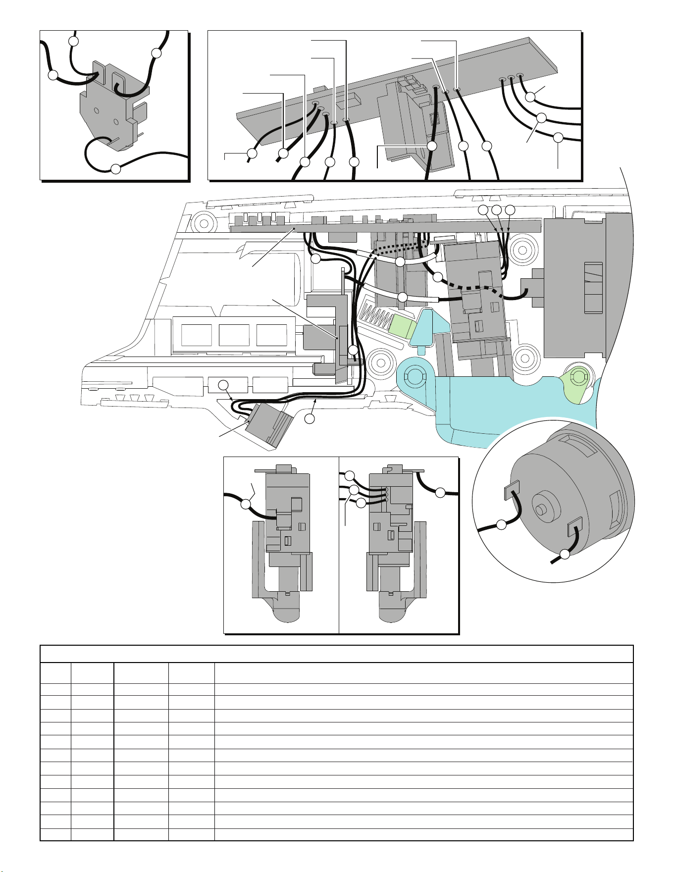
RED to PCB
RED
to Switch
BLACK
to PCB
WHITE to PCB
RED to Motor
BLACK to Connector Block
RED to
Connector Block
BLACK
to Switch
WHITE to Connector Block
WHITE to LED
RED to LED
WHITE to Motor
BLUE
to Switch
YELLOW
to Switch
BLACK to Switch
6
6
5
RED
to PCB
WHITE to PCB
1
7
12
11
10
YELLOW
BLK
BLUE
RED to
Connector
Block
BLACK
to PCB
CONNECTOR BLOCK
PCB ASSEMBLY
MOTOR
ASSEMBLY
SWITCH
LED
CONNECTOR BLOCK
PCB ASSEMBLY
MOTOR
ASSEMBLY
SWITCH
9
8
4
3
1
7
6
12
11
10
NOTE:
Black wire #2 (on the opposite
side of Terminal Block) and
red wire #5 (on the opposite
side of Motor Assembly) are
not shown in this side view
for clarity.
Terminals, Connectors and 1 or 2 End Wire Preparation
Wire
Color
Origin or
Gauge
Wire
No.
Length
WIRING SPECIFICATIONS
AS AN AID TO REASSEMBLY,
TAKE NOTICE OF WIRE ROUTING AND
POSITION IN WIRE GUIDES AND TRAPS
WHILE DISMANTLING TOOL.
BE CAREFUL AND AVOID PINCHING
WIRES BETWEEN HANDLE HALVES
WHEN ASSEMBLING.
NOTE:
Switch Assembly (23-66-2840)
consists of: switch, PCB assembly,
connector block and LED assembly.
1 Red 23-66-2840 ----- Component of switch assembly. Soldered to switch and connector block as shown.
2 Black 23-66-2840 ----- Component of switch assembly. Soldered to connector block and PCB assembly as shown.
3 Black 23-66-2840 ----- Component of switch assembly. Soldered to connector block and PCB assembly as shown.
4 White 23-66-2840 ----- Component of switch assembly. Soldered to connector block and PCB assembly as shown.
5 Red 23-66-2840 ----- Component of switch assembly. Soldered to motor assembly and PCB assembly as shown.
6 White 23-66-2840 ----- Component of switch assembly. Soldered to motor assembly and PCB assembly as shown.
7 Black 23-66-2840 ----- Component of switch assembly. Soldered to switch and PCB assembly as shown.
8 Red 23-66-2840 ----- Component of switch assembly. Routed from LED and soldered to PCB assembly as shown.
9 White 23-66-2840 ----- Component of switch assembly. Routed from LED and soldered to PCB assembly as shown.
10 Black 23-66-2840 ----- Component of switch assembly. Route from switch and soldered to PCB assembly as shown.
11 Yellow 23-66-2840 ----- Component of switch assembly. Route from switch and soldered to PCB assembly as shown.
12 Blue 23-66-2840 ----- Component of switch assembly. Route from switch and soldered to PCB assembly as shown.