54-38-1575
58-01-1370990A
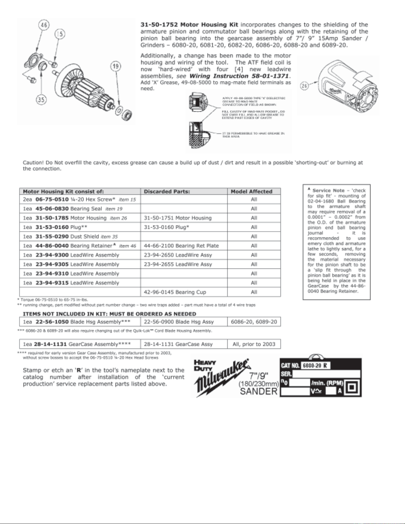
6082-20
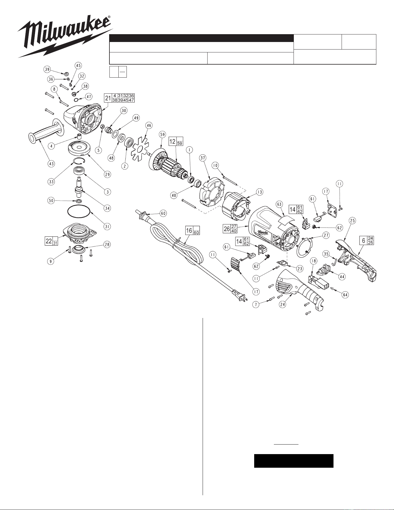
FIG. PART NO. DESCRIPTION OF PART NO REQ.
1 02-04-1675 Ball Bearing (1)
2 02-04-1680 Ball Bearing (1)
3 02-04-1745 Ball Bearing (1)
4 02-50-2429 Needle Bearing (1)
5 06-55-2455 Hex Nut (1)
6 14-34-0565 Handle Kit (1)
7 06-82-0055 8-16 Torx Plastite Screw T-20 (5)
8 06-82-0060 10-14 Torx Plastite Screw T-25 (4)
9 06-82-0065 10-32 x 1 Pan Hd. Taptite T-25 Screw (3)
10 06-82-0070 8-16 Torx Plastite Screw T-15 (2)
11 06-82-7240 6-19 x 1/2 Slt. Pan Hd. Plast. T-15 (3)
12 16-70-0132 Armature Assembly (1)
13 18-70-1130 Field (1)
14 22-20-0120 Brush Holder Assembly (2)
16 22-64-3600 Cord Set (Incl. Cord Protector and Terminals) (1)
17 23-44-0255 Brush Cover (2)
18 23-66-2725 Switch (1)
21 28-14-1131 Gearcase Assembly (1)
22 28-53-0151 Spindle Hub Assembly (1)
23 31-15-0166 Cover (1)
24 --------------- Left Hand Handle Halve (1)
25 --------------- Right Hand Handle Halve (1)
26 31-50-1751 Motor Housing Assembly (1)
27 31-53-0160 Plug (1)
28 31-55-0150 Bearing Shield (1)
29 32-05-1505 Gear (1)
30 32-60-1505 Pinion Gear (1)
31 34-40-0505 O-Ring (1)
32 34-40-4300 O-Ring (1)
33 34-80-2960 Retaining Ring (1)
34 38-50-2500 Spindle Shaft (1)
35 40-50-1375 Flat Spring (1)
36 40-50-1550 Compression Spring (1)
37 42-14-0425 Baffle (1)
38 42-30-0150 Lock Body (1)
39 42-42-0290 Button (1)
7/9" SANDER
REVISED BULLETIN
SERVICE PARTS LIST
BULLETIN NO.
WIRING INSTRUCTION
DATE
SPECIFY CATALOG NO. AND SERIAL NO. WHEN ORDERING PARTS
SERIAL
NUMBER
CATALOG NO.
MILWAUKEE ELECTRIC TOOL CORPORATION
13135 W. LISBON RD., BROOKFIELD, WI 53005
Drwg. 7
FIG. PART NO. DESCRIPTION OF PART NO REQ.
40 42-96-0145 Bearing Cup (1)
43 43-62-1265 Side Handle (1)
44 44-20-0501 Rotating Handle Lever (1)
45 44-60-1650 Lock Pin (1)
46 44-66-2100 Bearing Retaining Plate (1)
47 34-40-4555 O-Ring (1)
48 45-06-0710 Seal (1)
49 45-88-7880 Shim Washer (1)
50 45-88-8466 5/8-11 Spindle Washer (1)
59 22-84-0540 Fan Assembly (1)
FIG. LUBRICATION:
EXAMPLE:
Component Parts (Small #)
Are Included When Ordering
The Assembly (Large #).
0
00
Fig. nos. 5, 30, 49,
48, 2, 46, 1 and 40 are
assembled onto the
armature in the order
shown, before installing
into
gearcase.
FIG. PART NO. DESCRIPTION OF PART NO REQ.
60 44-76-0325 Cord Protector (1)
61 22-18-0126 Carbon Brush Assembly (2)
62 --------------- Brush Spring (2)
63 12-99-5000 Nameplate Blank (1)
64 05-78-0305 Switch Screw (4)
23-94-2650 Leadwire Assembly (1)
23-94-2655 Leadwire Assembly (1)
21 1.25 oz. (35 grams) of Type "Y" grease, No. 49-08-5270 in
main gear cavity of gearcase.
29,30 "Y" grease must be applied to all gear teeth.
31,32 Lightly coat o-rings with "Y" grease prior to installation.
FIG. NOTES:
4,21 Press needle bearing flush ±.02 to gearcase boss face.
33 Bevel side of retaining ring away from bearing face.
1,40 Seat bearing cup completely onto ball bearing.
FIG. NOTES:
5 Torque to 140 in.-lbs.
7,10 Torque to 20 in.-lbs.
8 Torque to 30 in.-lbs.
9 Torque to 35 in.-lbs.
64 Torque to 4 in.-lbs.
SEE BACK PAGE FOR
IMPORTANT SERVICE NOTES
Aug. 2007