READ IT OR WATCH IT
Read instructions or watch easy-to-follow video.
Scan QR code or visit http://bit.ly/2Woacod
41081
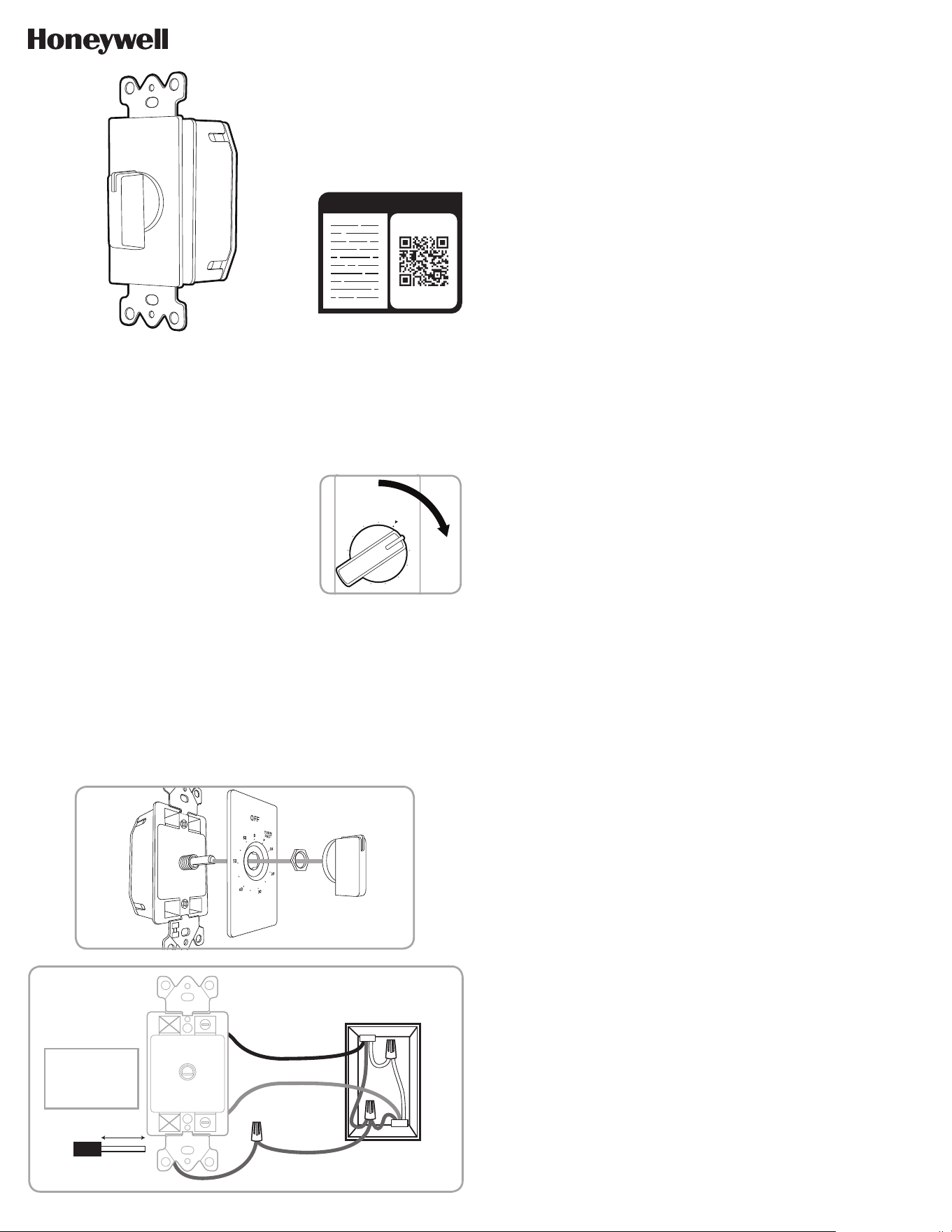
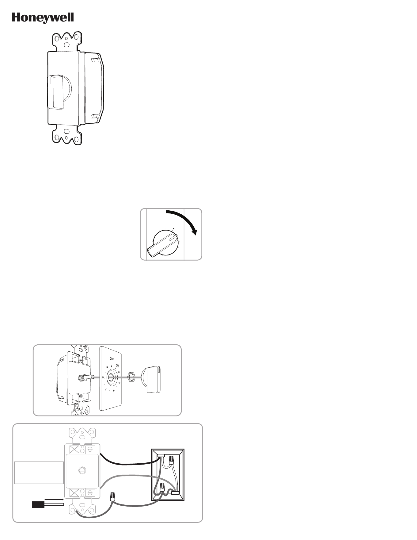
60-MINUTE SPRING-WOUND
IN-WALL TIMER
OPERATION
Turn knob clockwise to desired time period. Make sure
to turn past the 5 minute marker. (See Figure 1)
Timer will automatically turn off at end of period.
INSTALLATION
Note: If you are unsure or unclear about this installation
or if the wires in your box do not match the manual (not all switch boxes have neutral
wires), contact a qualified, licensed electrician.
1. Turn OFF the main power at the circuit breaker or fuse box.
2. Remove the existing switch. Determine which wires are line (hot), load and ground.
Label wires and disconnect.
a) GROUND - Green/bare
b) LOAD - Black (connected to lighting)
c) LINE (HOT) - Black (connected to power)
3. Carefully remove the knob, nut and faceplate from the timer. (See Figure 2).
30
40
60
OFF
TURN
PAST
0
10
20
50
Figure 1
4. Attach the bare ground wire from the timer to the green or bare ground wire in the
wire box using wire nut.
5. Loosen the LINE1 and LOAD1 screws (see Figure 3) with either a flat-head or Phillips
head screwdriver. When loosening screws, stop when you feel resistance.
6. Insert the Line wire from the lighting into the hole marked LINE1 and tighten the
screw.
7. Insert the Load wire from the electrical service panel into the hole marked LOAD1 and
tighten the screw.
Note: Tightening torque should be 12 lbf-in (14kgf-cm)
8. Tuck the wires into the wall box, leaving room for the timer.
9. Use the supplied screws to mount the timer to the wall box, being careful not to crush
any wires.
10. Reinstall your wallplate.Reinstall timer dial and center.
11. Turn the main power on at the circuit breaker.
12. If the timer does not turn on, disconnect the power at the circuit breaker and fuse box
and check connections.
Figure 2
TIMER
TIMER
5/8in. (1.6cm)
Wire strip length
WIRE
WALL BOX
Line
Load
Ground
Insert wires into
holes, do not
wrap wires
around screws.
Do not remove
screws.
LOAD2
LINE2 LINE1
LOAD1
TOP
Line - Black
Load - Black
Neutral - White
Ground - Green
or Bare
Figure 3 - Connecting the timer wires
125VAC, 50/60Hz
20A general/resistive
7A tungsten
1HP motor
250VAC, 50/60Hz
10A general/resistive
2HP motor
277VAC, 50/60Hz
10A general/resistive
Questions? Contact our U.S.-based Consumer Care at 1‑855‑698‑8324,
Monday–Friday, 7AM–8PM CST.
For the most up-to-date product support, accessories, electronic (PDF) format manuals and
more, visit www.byjasco.com/support.
DO NOT RETURN THIS
PRODUCT TO THE STORE
STOP
SPECIFICATIONS
RISK OF ELECTRICAL
SHOCK
• INSTALLATION BY A
LICENSED ELECTRICIAN IS
RECOMMENDED
• INSTALLATION AND USE OF
THIS EQUIPEMENT SHOULD
BE IN ACCORDANCE WITH
PROVISIONS OF THE U.S.
NATIONAL ELECTRICAL
CODE, APPLICABLE LOCAL
CODES AND PERTINENT
INDUSTRY STANDARDS
• SHUT OFF POWER AT THE
FUSE BOX OR CIRCUIT
BREAKER BEFORE
INSTALLATION
• DO NOT USE IN WET LOCATIONS
• FOR INDOOR USE ONLY
UNLESS INSTALLED IN A
NEMA TYPE 3R ENCLOSURE
RISK OF FIRE
• USE COPPER WIRE ONLY
WITH THIS DEVICE
• DO NOT EXCEED
ELECTRICAL RATINGS
• DO NOT USE TO CONTROL
RECEPTACLES
• DO NOT USE TO CONTROL
APPLIANCES WITH HEATING
ELEMENTS (COOKING
APPLIANCES, HEATERS,
IRONS, ETC.)
WARNING
Jasco Products Company LLC.
10 E. Memorial Road
Oklahoma City, OK 73114
The Honeywell Trademark is used under license from Honeywell International Inc.
Honeywell International Inc. makes no representation or warranties with respect to this product.
This product is manufactured by Jasco Products Company LLC.
This Jasco product comes with a 2-year limited warranty. Visit www.byjasco.com for warranty details.
MADE IN CHINA/HECHO EN CHINA
©JASCO 2019 | 41081 | 05/17/19 v1
41081
TEMPORIZADOR DE PARED ROTATIVO
DE 60 MINUTOS
FUNCIONAMIENTO
Gire la perilla hacia la derecha para seleccionar el
tiempo deseado. Asegúrese de pasar la marca de los
5 minutos. (Ver Figura 1)
El temporizador se apagará automáticamente al
finalizar el tiempo marcado.
INSTALACIÓN
Nota: si no está seguro o duda acerca de esta instalación o si los cables de la caja que
usará no coinciden con el manual (no todas las cajas de interruptores tienen cables
neutros), comuníquese con un electricista calificado con licencia.
1. Interrumpa la corriente principal al disyuntor o panel de fusibles.
2. Retire el interruptor existente. Determine cuáles son los cables con corriente
(line/hot), carga (load) y tierra (ground). Etiquete los cables y desconéctelos.
a) TIERRA (GROUND): verde/pelado
b) LOAD (CARGA): negro (conectado a la iluminación)
c) LíNEA (LINE/HOT): negro (conectado al suministro eléctrico)
30
40
60
APAGADO (OFF)
GIRE MÁS ALLÁ
DE LA MARCA
(TURN PAST)
0
10
20
50
Figura 1
3. Quite con cuidado la perilla, la tuerca y la tapa del temporizador. (Ver Figura 2).
4. Conecte el cable a tierra pelado del temporizador al cable a tierra pelado o verde de la
caja de cables con un empalme de cable.
5. Afloje los tornillos LINE1 y LOAD1 (Ver Figura 3) ya sea con un destornillador de
cabeza plana o Phillips. Al aflojar tornillos, deténgase al sentir resistencia.
6. Introduzca el cable de línea proveniente de la iluminación en el orificio marcado
LINE1 y apriete el tornillo.
7. Introduzca el cable de carga proveniente del panel de servicio eléctrico en el orificio
marcado LOAD1 y apriete el tornillo.
Nota: el par de apriete debe ser de 14 Kgf-cm (12 lbf-in).
8. Introduzca los cables en la caja de embutir, dejando espacio para el temporizador.
9. Use los tornillos provistos para instalar el temporizador en la caja de embutir,
teniendo cuidado de no apretar los cables.
10. Vuelva a instalar la placa de pared, el dial del temporizador y el centro.
11. Restablezca la corriente principal en el disyuntor.
12. Si el temporizador no enciende, desconecte el suministro eléctrico en el disyuntor y
en el panel de fusibles y controle las conexiones.
Figura 2
TEMPORIZADOR
TEMPORIZADOR
5/8 pulg. (1,6 cm)
Longitud de cable
sin aislamiento
CABLE
CAJA DE EMBUTIR
Línea (Line)
Carga (Load)
Tierra (Ground)
Inserte los cables
en los orificios,
no enrosque los
cables alrededor
de los tornillos.
No quite los
tornillos.
CARGA 2
LÍNEA 2 LÍNEA 1
CARGA 1
TOP
Line (Línea) - Negro
Load (Carga) - Negro
Neutral (Neutro) - Blanco
Ground (Tierra) - Verde
o pelado
Figura 3 - Cómo conectar los cables del temporizador
125VCA, 50/60Hz
20A general/resistiva
7A tungsteno
Motor de 1 HP
250VCA, 50/60Hz
10A general/resistiva
Motor de 2 HP
277VCA, 50/60Hz
10A general/resistiva
¿Preguntas? Comuníquese con nuestro Centro de atención al cliente con sede en EE. UU. al
1‑855‑698‑8324, de lunes a viernes, de 7:00 a. m. a 8:00 p. m. CST (hora central estándar).
Para recibir el soporte técnico más actualizado sobre productos, accesorios, manuales en
formato digital (PDF), entre otros, visite www.byjasco.com/support
ESPECIFICACIONES
RIESGO DE DESCARGA
ELÉCTRICA
• SE RECOMIENDA QUE UN
TÉCNICO ELECTRICISTA
REALICE LA INSTALACIÓN DE
ESTE PRODUCTO.
• LA INSTALACIÓN Y EL
USO DE ESTE EQUIPO
DEBEN REALIZARSE EN
CONFORMIDAD CON LAS
DISPOSICIONES DEL CÓDIGO
ESTADOUNIDENSE DE
NORMAS DE ELECTRICIDAD
(NEC), LOS CÓDIGOS
LOCALES APLICABLES Y LAS
NORMAS DE LA INDUSTRIA
CORRESPONDIENTES.
• INTERRUMPA EL
SUMINISTRO DE ENERGÍA
DESDE EL PANEL DE
FUSIBLES O EL DE
CORTACIRCUITOS ANTES
DE PROCEDER A LA
INSTALACIÓN.
• NO UTILICE EN LUGARES
HÚMEDOS
• PARA USO EN LUGARES
CERRADOS ÚNICAMENTE, A
MENOS QUE SE INSTALE EN
UNA CAJA NEMA TIPO 3R.
RIESGO DE INCENDIO
• USE SOLO CABLES
DE COBRE CON ESTE
DISPOSITIVO.
• NO SUPERE LOS VALORES
NOMINALES ELÉCTRICOS.
• NO UTILICE EL DISPOSITIVO
PARA CONTROLAR
TOMACORRIENTES
• NO UTILICE PARA
CONTROLAR APARATOS CON
RESISTENCIAS ELÉCTRICAS
(APARATOS DE COCCIÓN,
CALEFACTORES, PLANCHAS,
ETC.)
ADVERTENCIA
NO DEVUELVA ESTE
PRODUCTO A LA TIENDA
¡PARE!